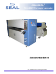
1
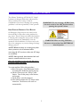
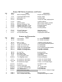
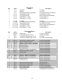
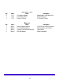
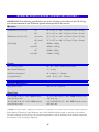
ATC-UV-60
ATC-UV-80
Owner’s Operation Manual
TAB L E OF C ON TE N TS
TABLE OF CONTENTS. ...........................................................................................................................................................2
INTRODUCTION...................................................................................................................................................................... .3
IMPORTANT SAFEGUARDS..................................................................................................................................................4
SAFETY FEATURES................................................................................................................................................................. .7
UNCRATING AND INSTALLING. .......................................................................................................................................8
ELECTRICAL CABINET FEATURES ................................................................................................................................ .9
CONTROL PANELS ................................................................................................................................................................10
OVERVIEW OF OPERATING FEATURES. ................................................................................................................... 13
LACQUER SUPPLY OPERATION.......................................................................................................................................14
SET-UP AND OPERATION...................................................................................................................................................15
SHUT-DOWN OPERATION. ............................................................................................................................................... 17
CLEANING THE COATING MACHINE..........................................................................................................................18
MAINTAINING THE COATING MACHINE..................................................................................................................19
UV LAMP OPERATION / MAINTENANCE...................................................................................................................20
ROLLER SPEEDS AND COATING RESULTS. .............................................................................................................. 21
SPARE PARTS LIST. ................................................................................................................................................................ 23
INSTRUCTIONS FOR LEVELING ROLLERS.................................................................................................................27
TROUBLESHOOTING GUIDE............................................................................................................................................28
MOTOR CONTROL KEYPAD PROGRAM. .....................................................................................................................29
TECHNICAL SPECIFICATIONS (COATING SECTION ONLY) .............................................................................30
LIMITED WARRANTY. ......................................................................................................................................................... 31
Alliance Technology Corporation. ............................................................................................32
© 2007 Alliance Technology. ...................................................................................................32
Part #OMAC60_80 UV-E Rev. A. ............................................................................................32
2
IN TR OD U C TION
Thank you for purchasing a Alliance Technology
ATC 60/80 UV Liquid Laminator. We have
designed the ATC60/80 UV Liquid laminator to
give you years of reliable service. As you become
familiar with your liquid laminator, you will
appreciate the high quality of its production and the
excellence in its engineering design.
STATEMENT OF INTENDED USE
The ATC60/80 UV laminator is intended for use
with medium and large format graphic output.
Graphics can vary in widths from 100mm –
2032mm (4” – 80”). Mounted graphics can be up
to 76mm (3 in.) thick. The ATC60/80 UV liquid
laminator is intended for use with Alliance
Technology ATC lacquer only. Use of other
manufacturer’s lacquers may damage the machine
and will void any warranty.
By following the guidelines for proper care and use
of the ATC60/80 UV, you can depend on many
years of trouble-free profitability from your
investment.
WARNING! This laminator is designed for
liquid laminating. Any use other than the
intended may cause damage to the laminator
or physical harm to the user.
Please read and fully understand the entire
manual before proceeding to use your
laminator.
WARNING! Any unauthorized changes or
modifications to this unit without our prior
written approval will void the user’s warranty
and will transfer health and safety obligations
to the user.
CAUTION! Please pay attention to all shaded
passages. This information is vital to
preventing user injury and/or damage to the
unit. Failure to follow this information could
void the user’s warranties and transfer all safety
obligations to the user.
LIABILITY STATEMENT
The details given in this manual are based on the
most recent information available to us. They may
be subject to change in the future. We retain the
right to make changes to the construction or the
design of our products without accepting any
responsibility for modifying earlier versions
previously delivered.
3
IM P OR TAN T S AF E GU AR D S
SAFETY INSTRUCTIONS
IMPORTANT! When using any equipment,
always follow the manufacturer’s instructions
for safe operation.
Make sure machine is connected to the proper
power source.
Familiarize yourself with the layout of the Control
Panel, and with the operation of the lacquer
delivery system.
To obtain MSDS Sheets for ATC60/80 UV
Products, please call Alliance Technology at 410634-9381.
Comply with all safety warning signs, labels, and
instructions.
SAFETY WARNINGS
Operators should be trained on the proper use of
the machine and all safety procedures.
Provide ventilation, eye protection, clean towels
and rubber gloves for use during cleanup.
It is advisable to wear eye protection when
filling/emptying lacquer tank. Always provide an
approved emergency eyewash station adjacent to
the machine.
In case of skin contact with uncured lacquer, use
soap and water to clean (do not use solvents to
remove lacquer from the skin—solvents help
lacquer to penetrate the skin). Repeated skin
contact will result in a skin rash--uncured UV liquid
is a skin irritant. Cured UV liquid does not irritate
the skin. (1 box of latex gloves has been shipped
with the machine.)
Review MSDS prior to working with UV material.
WARNING! Ensure a clean well-ventilated
work area. Avoid direct skin contact with
uncured UV lacquer. Wear rubber gloves and
UV blocking safety glasses. Failure to avoid
contact with hot surfaces may cause burns. Do
not look directly at the UV light source.
CAUTION! When handling any chemical
products, read the manufacturers’ container
labels and the Material Safety Data Sheets
(MSDS) for important health, safety, and
environmental information. Always observe
manufacturers recommendations when
handling chemicals.
ROTATING PARTS: RISK OF INJURY
CAUTION! Failure to use caution near
rotating rollers could result in physical injury.
Be careful that items such as loose clothing,
long hair and jewelry do not become entangled
in rotating parts.
Beware of pinch points. Never operate machine
with protective covers removed. Keep hands
outside of machine when feeding materials into the
machine. Never reach into machine when rollers
are moving.
4
IM P OR TAN T S AF E GU AR D S ( C ont inue d)
ELECTRICAL PARTS – DANGER OF BEING INJURED BY
ELECTRICITY
WARNING! Do not open electrical cabinet
panels because of the risk of being injured by
voltage. Only authorized maintenance and
service technicians or safety personnel should
have access to the electrical cabinet for
mechanical /electrical upkeep or repair.
IMPORTANT! Do not place heavy objects on
the power supply cord.
PREVENTATIVE MEASURES:
Do not feed objects such as staples, paper clips and
rough or abrasive materials through the laminating
rollers.
Keep all objects, such as tools, rulers, pens, markers
or knives away from the roller opening. Refrain
from leaving such items on the tables to prevent
them from accidentally being fed into the rollers.
IMPORTANT! NEVER cut or slice directly on
the EPDM covered roller as any cuts, dents or
gouges will destroy it and adversely affect the
output. ALWAYS use cutters with enclosed
blades to prevent cutting the roller and to avoid
extensive replacement costs.
UV Light Safety:
Never look directly at the UV curing lamps. If
working for extended periods at the machine wear
UV blocking glasses (clear or tinted). Over
exposure to UV light will result in a condition
colloquially known as “welder's flash”--the eyes will
itch and burn or feel sandy for a period of time.
This condition should be avoided. Permanent eye
damage can result. (2 sets of tinted eyeglasses have
been shipped with the machine.)
IMPORTANT! Read the UV CURING
SAFETY
MANUAL for further safety
information before operating the UV60-80
coating machine.
5
IM P OR TAN T S AF E GU AR D S ( C ont inue d)
Service Technicians must perform safety
checks after completing any service or repairs
to the laminator.
SERVICING AND REPLACEMENT PARTS
Service and maintenance must be performed fully
in accordance with the instructions. Servicing by
any unauthorized technician voids the warranty.
The service technician must use replacement parts
specified by Alliance Technology.
WARNING! If your laminator does not operate
correctly, contact Technical Service
immediately.
6
S AF E TY FE ATU R E S
The Alliance Technology ATC60/80 UV Liquid
Laminator is designed with safety and protective
devices with the user’s safety of utmost
consideration. However, following safe operating
guidelines is still the responsibility of the operator.
WARNING! For any servicing, ALWAYS turn
the main switch to the OFF position before
opening the top side cabinet.
HAND-OPERATED EMERGENCY STOP BUTTONS
Six Emergency Stop buttons are located on the
front and sides of the roller coating machine for
easy access. These E-Stops are interlocked with the
UV drying unit’s emergency stop system. If either
switch is pressed, they immediately cease the
operation of both machines. Use these only in the
case of an emergency or you may damage an image
during a process.
WARNING! When servicing EMI filter
disconnect the machine from EXTERNAL
electrical power.
NOTE! Whenever there is an emergency shut
down you must wait 15 minutes before
restarting the UV section to allow the UV lamp
to cool down.
NOTE: Once pressed, these buttons lock and
must be turned clockwise to reset.
Once the machine is reset turn the fans on to
continue cooling the lamp.
To restart machine follow this procedure:
a) Reset Emergency Stop Mushroom Switch
by turning the mushroom until it pops up.
b) On the Coater press the “SR Set” push
button. Turn on the pump, roller motors,
and scraper.
c) On the Dryer, start the transport.
d) After fifteen minutes the UV lamps can be
turned on. The blowers will come on
automatically.
7
U NC R ATIN G AN D IN S TAL L IN G
See diagram on page 7 for the electrical
connections. The coater should be connected to the
electrical service through a disconnect ( plug or
switch ).
RECEIVING AND STORING CRATE.
The coating machine is shipped in a heavy duty
crate. The crate should be inspected for signs of
shipping damage at the time of arrival. Any
indications of handling damage should be
immediately reported to the carrier. Extreme hot
or cold temperatures (- 40 c to +60c ) will not
harm the machine. Avoid leaving the crate
outside: humidity will oxidize some parts.
CAUTION! When servicing the EMI filter in
the coater the machine will be disconnected
from the external electrical power.
The coater is ready to operate, after filling the
reservoirs with lacquer and alcohol.
LIFTING AND MOVING THE COATING MACHINE.
DRYER INSTALLATION.
To lift the machine from the shipping crate use a
forklift. The coater may be lifted and transported
by its bottom rails. Once the coater is on the floor a
pallet jack can be used to move it. Position the
coater and the dryer in their final location.
Approximately 36” is needed around the coater for
routine service ( access to the lacquer
reservoirs,alcohol ...etc.)
IMPORTANT! Read the INSTRUCTIONS
for the CONVEYOR CURE IRRADIATOR
OPERATION before installing the dryer.
The dryer's electrical connection is on the right
side. See diagram on page 7. The UV lamp is
packaged separately to protect it during transport.
Open the top cover, remove the lamp housing,
place it upside down on the dryer, remove the lamp
from its tube, HANDLE WITH COTTON
GLOVES, attach each lamp lead wire to the
ceramic standoffs located near the lamp ends.
Reinstall lamp housing, close top cover.
LEVELING THE COATING MACHINE.
Level both coater and dryer very carefully. When
leveling coater make sure to remove all twists from
the frame. In other words level both front to back
on the right side, front to back on the left side and
finally left to right.
Also on the dryer, on the left side, is located the
exhaust system. Connect it to an outside duct to
exhaust ozone. Install the four UV shields ( 2 in
front,2 in the back ).
ELECTRICAL CONNECTIONS.
8
E LE C TR IC AL C AB IN E T FE ATU R E S
Electrical Cabinet
1. Emergency Stop Buttons (6)
• Located on the front of the coater and all four
corners of the dryer they immediately cease the
operation of both machines.
2. Control panel system
• Turns On/Off the liquid laminator and provides
independent control of speed, roller direction of the
two rollers, selection of the pump, scraper, air
seperator, and the gages for the air supply to the air
seperator, the scraper, and the pinch roller. The
speed control is independent of the UV dryer unit’s
speed.
9
C ON TR OL PAN E LS
Coating Machine Electrical Controls:
10
C ON TR OL PAN E LS ( C ont in ue d)
ROLLER SPEED CONTROLS
The speed controls set the speeds of the roller
motors.
NOTE: The speed controls for the roller coating
machine are independent of the speed of the UV
dryer machine.
ON/OFF PUSHBUTTON
The On/Off Pushbutton controls the safety relay
that supplies power to the machine.
SCRAPER ADJUSTMENT
The scraper cleans the bottom roller. When
running un-mounted materials scraper adjustment
is critical. There should be no lacquer streaks on the
backs of coated materials. The scraper pressure is
controlled by air pressure. The coating roller
should be in the zero (down) position and the
lacquer pump should be on. Scraper adjustment is
controlled by an air valve labeled “Scraper
Pressure”. Generally the scraper is run at 30-50
psi. When cleaning the machine with alcohol,
scraper pressure should be reduced to 10-15 psi.
Never engage the scraper with the bottom roller
dry, ie always coat both rollers with lacquer before
engaging the scraper.
11
C ON TR OL PAN E LS ( C ont in ue d)
UV Dryer Electrical Controls:
UV LAMP AND CONVEYOR CONTROLS
For details consult the UV curing machine manual.
12
OV E RV IE W OF OP E R ATIN G FE ATU R E S .
ROLLER ASSEMBLY
ROLLER ADJUSTMENTS.
There are two roller adjustments. Pinch roller
pressure adjustment and coating roller elevation
adjustment. The pinch roller is directly in front of
the coating roller.
The roller assembly is the heart of the coating
machine. It uses a three-roller design.
The top front roller supplies lacquer to the coating
roller.
The pinch roller pressure is controlled by an air
pressure valve labeled “Pinch Roll Pressure”.
50 psi is the normal setting. For thicker coating
reduce the pressure. For thinner coating increase
the pressure.
The middle coating roller applies the lacquer to the
face of the image being coated.
The bottom roller presses the back of the image
material ensuring an even coating pressure.
A maximum amount of lacquer evenly distributed
across the whole roller provides the best coating
result.
Roller elevation is controlled by a hand wheel
adjustment.
English units: The digital readout
is calibrated in thousandths of an inch. The white
digits represent whole numbers, the three yellow
digits represent three digits to the right of a decimal
point, i.e.0.00i”to 0.999”
Metric units: the digital readout is calibrated in
hundreds of a millimeter . The LCD readout is
always on.
FEEDING MATERIALS THROUGH THE COATING ROLLER
Materials are fed face up through the roller
assembly under the middle coating roller.
13
L AC QU E R S U P P LY OP E R AT IO N
DUAL LACQUER AND CLEANING SUPPLY.
OPERATING TEMPERATURE.
The operating temperature of the machine is
determined by the temperature of the coating
liquid. Optimum temperature of the liquid is 68°F
(20°C), but it can be used between 65°F to 86° F
(18° – 30°C). Below 65°F (18°C) the liquid will
thicken, drain more slowly, and collect in the
drain pan. Above 86°F (30°C) the liquid thins,
and effective coating thickness will decrease.
There are three pumps and three drain valves. Two
pumps are dedicated to two types of coating liquid
(“L1” and “L2”). The third pump is for the
isopropanol 99% alcohol cleaning liquid.
IMPORTANT! Before starting the pump
always check the three drain valves--two should
be closed, one should be open. The open valve
must match the pump selected on the pump
selector switch.
Because the coating liquid will not cure unless it is
exposed to UV light, the machine does not have to
be cleaned daily. Once a week is sufficient. The
“L1” drain and the “L2” drain have in-line filters
to filter the lacquer being pumped in the machine.
Depending on the type of material being coated,
these filters will need to be cleaned on a periodic
basis. The wash system has an additional in line
filter.
14
S E T- U P AN D OP E R ATI ON
STARTING AND RUNNING THE MACHINE
minutes the exhaust blowers will come on
automatically.
First start the UV Dryer
Second allow the UV Lamp to warm up. When the
lamp is warm enough the fan will come on
automatically.
D. At this point, the lamp wattage can be
adjusted to the desired level. Standard mercury
lamps can be operated at 250 or 150 WPI
settings. As the lamp wattage is changed, the
amperage meter on the power supplies as well as
the wattage pilot light indicators will show at
what wattage level the UV lamp is operating.
Third start the Coating Machine
PERSONAL PROTECTION
WARNING! Always wear rubber gloves and
glasses when handling UV lacquers. If you get
lacquer on your skin, wash it off immediately
with soap and water. Do not use solvents to
remove lacquer from the skin—solvents help
lacquer to penetrate the skin.
E. The conveyor speed can be adjusted with the
Speed Control dial on the dryer's control panel.
A digital readout displays the conveyor speed in
feet per minute; turning the dial to the right
increases conveyor speed (to a maximum of 150
fpm) and turning the dial to the left decreases the
speed (to a minimum of 10 fpm.) By managing
speed and wattage levels the operator can control
overall UV exposure.
START UP:
A. Check lacquer supply. If you need to add to the
reservoir do so now. Also check the alcohol
cleaning reservoir. If you are running linty
materials (canvas) you will need to open and clean
the inlet filter for whichever coating lacquer you
have been using. The filter screen can be cleaned
by flushing with isoproponal alcohol.
F. Next we will set the roller gap. Turn the
hand wheel clockwise until the digital display
reads “000125”. The rollers should be separated
with an eighth inch gap.
CAUTION! Avoid skin contact with uncured UV
lacquer, if you get it on your skin wash it off
immediately with soap and water. Never use
alcohol to remove lacquer from the skin.
CAUTION! Wear eye protection if the UV
lamp is lit.
G. Check the pinch roller pressure setting-normally 50 psi. Press the green Top Roll
Motor push button. Press the Motor ON
keypad and set the roller speed knob to 70
FPM.
B. Look under the feed table and inspect the
scraper for cleanliness. If you are running clean
materials you may never have to clean the scraper,
if you are running canvas (linty materials) you
may need to clean the scraper on a regular basis.
H. Select L1 or L2 on the Pump Selector
Switch, open the 1st or 2nd drain handle (the W
drain handle should be closed). Turn on the
green Pump ON push button and adjust the
pump speed to one to two strokes per second.
Pump pressure should be 20-60 psi. Stroke rate
is controlled by adjusting the pump valve.
C. Turn on the Main Switches. Press the SR Set
button on the coater front panel. On the UV Dryer
panel, turn on the conveyor (with the Control
Power switch). Set the wattage level selection dial
to the 250 WPI mode. ALWAYS START THE
LAMP IN THE HIGH MODE. After a few
15
S E T- U P AN D OP E R ATI ON (C ont inue d)
I. Start bottom roll motor. Press green Bottom
Roll Motor push button. Press Motor ON
keypad. Adjust roller speed knob to 50 FPM.
CAUTION! Wear eye protection if the UV lamp
is lit.
J. Now we will bring the rollers together. Turn
the hand wheel counter clockwise until the digital
indicator reads all zeros. The rollers should be
touching with no light showing.
K. Finally activate the scraper. Press the green
Scraper ON push button. The scraper pressure
should be 30-50 psi.
16
S H U T- D OWN OP E R AT IO N
SHUT DOWN:
If the machine is installed in a dirty or light
environment – you must thoroughly clean!
A. Turn off UV lamp. This will begin a timed
cool down. ALWAYS SHUT DOWN THE
LAMP IN THE HIGH MODE.
If the machine is exposed to direct daylight or if
your overhead lighting is actinic (contains UV) you
must clean the machine with isopropanol alcohol.
Stray actinic light will cause the lacquer to cure in
the machine.
B. The main cooling fan will be timed on for a
minimum of five minutes. After the fan shuts off
the control power can be turned off at the dryer's
control panel.
IMPORTANT! Regardless of the environment
the machine should be cleaned once a week.
C. Press the red Lacquer Pump push button.
Close the pump valve.
D. If the coating roller is elevated, carefully
return it to zero position. In this position excess
lacquer on the top rollers will be transferred to the
bottom roller and scraped into the pan and
returned to the reservoir. After running until the
excess lacquer is gone, raise the top rollers off of
the bottom roller.
IMPORTANT! Leaving the rollers in contact
with each other can cause the rubber roller to
be dented along the pressure line. Many times
the dent can be removed by running the roller
with pressure applied--but to avoid the expense
of replacing the coating roller always elevate
the rubber coating roller off of the bottom roller
when you shut the machine down.)
E. Press the red Top Roll Motor push button.
Press the red Bottom Roll Motor push button.
Press the red Bottom Roll Scraper push button.
WARNING! Always wear rubber gloves and
glasses when handling UV lacquers. If you get
lacquer on your skin, wash it off immediately
with soap and water. Do not use solvents to
remove lacquer from the skin—solvents help
lacquer to penetrate the skin.
17
C LE AN I N G TH E C O ATI N G M AC H IN E
WARNING! Always wear rubber gloves and
glasses when handling UV lacquers. If you get
lacquer on your skin, wash it off immediately
with soap and water. Do not use solvents to
remove lacquer from the skin—solvents help
lacquer to penetrate the skin. When working
with alcohol avoid skin contact and provide
adequate ventilation.
Disposal of Chemicals
Use disposal methods in accordance with local
regulations when disposing the alcohol/lacquer
mixture.
CLEANING CYCLE:
The cleaning cycle is similar to a standard Start
Up. Wash is selected on the pump selector
switch and the “W” drain handle is turned to the
open position. With the rollers in contact, run the
machine for ten or fifteen minutes. Top and
bottom rollers should be set to the same FPM
(MPM) setting. The scraper pressure should be
in the 10-15 psi range.
If you are cleaning the machine to change to a
new lacquer that may be incompatible with the
old lacquer, after the first cleaning cycle replace
the alcohol and repeat the cycle.
CLEANING THE TRANSFER BELTS:
(The rollers should be separated with the bottom
roller running.) The transfer belts can be cleaned
“automatically” by filling the transfer belt tray
with alcohol. To do this, close the drain valve on
the tray (in the window under the feed table in the
center of the machine). Start the wash pump.
(Pump pressure should be 20 psi for alcohol.)
There are two valves exiting the wash pump, one
pointed at the top rollers, the other connected to
tubing that runs into the transfer belt tray.
Partially open the transfer belt tray valve (leave
the roller valve closed). When the transfer belts
are wetted with alcohol turn off the valve and turn
off the pump. Allow the machine to cycle for a
few minutes. Open the transfer tray drain valve to
drain the alcohol and leave it open.
18
M AIN TAI N IN G TH E C O ATI N G M AC H IN E
PUMP MAINTENANCE.
Lacquer viscosity can affect pump performance.
Lacquer viscosity is measured in Zahn seconds
using a #2 Zahn cup (supplied with machine).
Typically the lacquer will measure between 30 to
60 Zahn seconds.
There are three pneumatic pumps. Two for
lacquer, one for alcohol wash. The pumps are
identical. The pumps clip into brackets and are
completely removable.
19
U V L AM P OP E R ATI ON / M AI N TE N AN C E
Over time the UV output of the lamp will
weaken and the lamp will have to be replaced.
There is an hour meter wired into the lamp
circuit to track the total on-time of the lamp.
UV LAMP OPERATION AND MAINTENANCE.
The medium pressure UV lamps have a
characteristic start up. The quartz glass bulbs are
filled with argon and little droplets of mercury.
When high voltage is first applied to the lamp the
argon lights and glows. It is the glowing argon
that heats the bulb and evaporates the mercury. It
is the mercury vapor arc that produces UV
radiation. Because of this evaporation cycle,
when the lamp is turned off, wait 15 minutes
before restarting.
TURN OFF THE MAIN SWITCH.
To replace the lamp, open the lamp housing, lift
the reflector and set it to the side. The lamp
terminals can then be disconnected on each end
and removed.
IMPORTANT! Wear cotton gloves when
handling quartz lamps. Oil from the fingers
will mark the quartz when the lamp is heated
and cause failure. Wash the lamp surface with
clean propyl alcohol prior to starting for the
first time.
Repeated starts shorten the life of the UV bulb. It
is customary to light the bulb once each day.
Instead of turning off the lamp it is placed in
stand-by mode in between coating runs. There is
a stand-by position (Low) on the UV Lamp
High-Low selector switch.
The lamp on the UV 80 should be rotated every
30-40 hours to prevent the bulb from bowing.
Wear cotton gloves when you rotate the lamp.
The lamp on the UV 60 should be rotated every
60-80 hours.
20
R OLLE R S P E E D S AN D C O ATIN G RE S U LTS
ROLLER SPEEDS AND COATING RESULTS.
SUBSTRATES:
Top and bottom roller speeds are independently
controlled allowing a great deal of flexibility in
coating results.
Styrene: Stable product coats evenly.
Foam Board: Coats evenly but falls off on edges-edges thinner than center.
Gator Board: Coats evenly.
Sintra: Coats evenly--material slightly thicker in
the middle.
Coreplast: Easy to coat.
Alumalite: Easy to coat.
There are basically two types of materials.
Thick materials which require the rollers to be
set with a gap (material thickness minus 0.012”
[0.3mm]) and thin materials which are run
through closed rollers with the bottom roller
scraper engaged.
Sample set up speeds for thick substrates: 100 top
roller / 50 bottom roller / 55 dryer.
For smoother texture: 60 top roller/ 30 bottom
roller / 35 dryer.
ROLLER SPEEDS WITH THICK MATERIALS.
The thickness of the coating can be controlled
by varying the ratio of top to bottom roller
speeds. The faster the top roller, the thicker the
coating. The coating is even across the entire
width of the machine. Thickness is both
uniform and controllable. For example, paper
based materials that are absorbent (and in other
coaters required two or more passes to coat) can
be coated in a single pass. The only limit for
thick substrates is the uniformity of thickness of
the substrate. Substrates that are thick in the
middle and thin on the edges require very
careful roller setting--and if there is too much of
a center to edge difference the edges will not
coat. Substrates with dings or dents will not
coat in the dented area. Coating texture is
controlled by the overall speed of the machine.
Running in a slower range will produce
smoother coating texture.
Thin substrates require more attention. First there
is the scraper. The scraper needs to be properly
applied and adjusted so that the backs of coated
materials do not pick up UV lacquer.
Thin materials can adhere to the coating roller-thin materials that have an affinity for wrapping
around the coating roller will need a leader, or
will need to be taped to a board, or will need to be
operated using a roll feed and take up system.
Materials that have enough weight (stiffness) will
coat without problems. Decal material and
cyclone paper fall into this category. Materials
that are very light tend to ride up the coating
roller on the exit side of the nip. Light weight
banner material exhibits this property. Where it
rides up and separates from the roller can result in
a rough texture to the coating. To properly coat
light
21
R OLLE R S P E E D S AN D C O ATI N G R E SU LTS (c ont inue d)
weight materials tension must be maintained on
the exit side of the nip. This can be
accomplished by use of a long leader (long
enough to extend through the dryer), or through
use of a roll feed and take up system.
MATERIALS:
(Run with the aid of the 9 nozzle air separator
system.)
Decal material (adhesive backed).
Cyclone paper (coated paper for ink jet printers).
Sample set up speeds for decal paper: 30 top
roller / 40 bottom roller / 45 dryer. In this
situation running the top roller slower than the
bottom roller discourages wrapping.
22
S PAR E PAR TS LIS T
Qty.
1
1
1
6
Rollers and Bearings
Part #
CA-1
CA-5
MF-14
CA-6
AP-13
AP-22
Rubber Roller
Pinch Roller
Bottom Roller
Pillow Block Bearings
ARTroller
BearingsMOD
Description
6” x 66” x 1-1/2” shafts
5” x 66” x 1-1/2” shafts
6” x 66” x 1-1/2” shafts
1-1/2” bore
2” x 60” x 1” shafts
1” bore
1
2
CA-1-80
CA-5-80
MF-14-80
CA-6-80
AP-13-80
AP-22
Rubber Roller
Pinch Roller
Bottom Roller
Pillow Block Bearings
ARTroller
BearingsMOD
9” x 90” x 2” shafts
8” x 90” x 2” shafts
9” x 90” x 2” shafts
2” bore
2” x 84” x 1” shafts
1” bore
Qty.
1
1
1
1
1
1
Part #
CA-7
CA-8
CA-9
CA-10
CA-3
CA-4
NordGearMotor
Gearbelt18Pulley
Pulley Bushing
Gearbelt
Gearbelt22Pulley
Pulley Bushing
Description
Top roller motor
Motor Pulley
¾” bore
Motor Drive Belt
Roller Pulley
1-1/2” bore
1
1
1
1
1
1
CA-7-80
CA-8-80
CA-9-80
CA-10-80
CA-3-80
CA-4-80
NordGearMotor
Gearbelt28Pulley
Pulley Bushing
Gearbelt
Gearbelt32Pulley
Pulley Bushing
Top roller motor
Motor Pulley
¾” bore
Motor Drive Belt
Roller Pulley
2” bore
1
1
1
1
MF-9
MF-10
MF-11
MF-12
RightAngleMotor
LovejoyCoupling
LovejoyCoupling
LovejoyCoupling Spider
Bottom roller motor
1” bore
1-1/2” bore
1
1
1
1
MF-9-80
MF-10-80
MF-11-80
MF-12-80
RightAngleMotor
LovejoyCoupling
LovejoyCoupling
LovejoyCoupling Spider
Bottom roller motor
1-1/8” bore
2” bore
1
1
1
1
AP-16
AP-17
AP-18
AP-19
40BS11 Sprocket
40BS36MOD Sprocket
#40 Chain
#40 Connector
For ART roller
On bottom roller shaft
40
80
20
20
AP-10
AP-11
AP-20
AP-21
Pulleys, white plastic
Washers
Belts
Aluminum Connectors
For Yellow belts
Pulley spacers
1/4” Roundthane belts
For Roundthane belts
1
2
1
1
1
6
Name
Motors and Mechanical Drive Components
Name
23
Qty.
Pumps, Ball Valves, Containers, and Drains
3
Part #
PD-6
Name
4UN14, Diaphragm Pump
Description
Lacquer and wash pumps
1
1
8
PD-9
PD-9.1
PD-10
Polypropylene Ball Valves
Brass Street Tee
Hose Barbs
Lacquer valves
For wash valve
1/4”npt x 3/8” barb, polypropylene
3
3
3
3
3
10
PD-36
PD-37
PD-38
PD-39
PD-40
PD-41
Carboy
Suction Strainer
SS Hose Straigtener Tube
3/8Plastic hose barb x ½ mpt
5/8Brass hose barb x ¾ mpt
7/32" To 5/8" Clamp Id Range
5 gallon container
Nylon Suction Strainer 30 Mesh
5/16 X .035 X 9” SS tubing
For suction strainer
For carboy cap
SS tubing clamps
1
2
1
PD-15
PD-24
PD-17
3/4” npt SS ball valve
1” npt SS ball valve
3/4” fnpt screen filters
Wash drain valve
Lacquer drain valves
Polypropylene wash filter
Qty.
1
1
Part #
SP-66
SP-90
UV60 scraper
UV80 scraper
Description
66” Urethane Squeegee
90” Urethane Squeegee
1
2
3
7
12
2
4
SP-22
PD-4.1
SP-29
PD-5.2
PD-5.3
PD-1.1
PD-1.2
Nylon 11 Tube
¼ X 5/16 Swivel EL
¼ Nptf X 5/16 Swivel Tee
¼ Nptf X 5/16 Push Tee
¼ Nptf X 5/16 Straight Male
1/8 Nptf x 5/16 Swivel Tee
1/8 Nptf x 5/16 straight Male
.232IDX5/16ODX.040 WALL
For air cylinders and valve panels
For valve panels
For valve panels
For air cylinders and valve panels
For pump air solenoid
For pump air solenoid
1
1
3
3
1
SP-25
SP-30
PD-4
PD-5
BOS-16
Air Line Filter
Micro Mist Lube
Air Pressure Gage
1/4” Air Regulator Valve
1” Air Regulator Valve
Incoming air filter
Air cylinder lubricator
Panel gages
Panel air regulators
For blow-off system
2
2
1
CA-27
CA-27-80
SP-5
Air Cylinder for pinch roller
Air Cylinder for pinch roller
Air Cylinder for scraper
2" Bore, 3/8" Stroke Length
2" Bore, 7/8" Stroke Length
2" Bore, 1-1/2" Stroke Length
1
1
1
1
1
4
BOS-22
BOS-22.1
BOS-20
BOS-19
BOS-21
BOS-31
Air receiver
Pressure relief valve
1-1/2” EPDM Rubber Hose
1-1/2” Npt x 1-1/2 Hose barb
1-1/2” Npt Street El
Worm-Drive Hose Clamp
20 Gallon Air Tank
100 psi
15' , 150 psi rating
For EPDM Hose
For EPDM Hose
1-13/16" to 2-3/4" Clamp ID Range
9
9
BOS-4
BOS-3
High Pressure Air Nozzles
1/8” X 1/8mnpt brass fittings
Blow-off nozzles
Compression fittings for nozzles
Scraper and Pneumatics
Name
24
Lifter Parts
Qty.
2
2
1
1
1
1
1
Part #
LP-1
LP-2
LP-3
LP-13
LP-13.1
LP-14
LP-14.1
2
1
1
1
1
1
LP-1-80
LP-3-80
LP-13-80
LP-13.1-80
LP-14-80
LP-14.1-80
Name
Screwjack
Miterbox
3/8" Minature Keyless Shaft Mount
Tejax Digital Counter
LCD Digital Counter
Hand Wheel + 1” shaft
Hand Wheel + ¾ “ shaft
Description
For UV60
For UV60
Screwjack disconnect on left side
Inch readout for UV60
Metric readout (programmable)
6” hand wheel x 1”
6” hand wheel x ¾ “
Screwjack
½" Minature Keyless Shaft Mount
Tejax Digital Counter
LCD Digital Counter
Hand Wheel +1” shaft
Hand Wheel + ¾ “ shaft
For UV80
Screwjack disconnect on left side
Inch readout for UV80
Metric readout (programmable)
9” hand wheel x 1”
9” hand wheel x ¾ “
Electrical Parts
Qty.
1
1
3
2
Part #
BOS-23
BOS-9
PD-1
SP-13
Name
Photosensor
1” Npt Solenoid valve, 24 vdc
1/8” Npt Air Solenoid valve, 24 vdc
1/4” Npt Air Solenoid Valve, 24 vdc
Description
For blow-off system
For blow-off system
For pump
For scraper and pinch roller
2
2
1
1
4
4
1
9
2
2
EP-13
EP-14
EP-15
EP-20
EP-17
EP-18
EP-18.1
EP-18.2
EP-2.1
EP-21
Red E-STOP mushroom switch
Yellow E-Stop legend plate
Selector switch 3 position, maintained
Selector switch 2 position, maintained
Red Push Button
Green Push Button
Blue Push Button
Replacement Lamp for pushbuttons
Replacement Motor Keypad
Keypad cable
For front control panel
For front control panel
For front control panel
For front control panel
For front control panel
For front control panel
For front control panel
For front control panel
For front control panel
For front control panel
2
2
2
2
1
EP-4
EP-5
EP-6
EP-30
EP-31
EDCC8 class CC TD 8A 600V
EDCC12 class CC TD 12A 600V
EDCC20 class CC TD 20A 600V
5 x20 Fuse 2.5 A
5x20 Fuse 6.3 A
Fuse for electrical box
Fuse for electrical box
Fuse for electrical box
Fuse for electrical box
Fuse for electrical box
1
1
2
2
1
3
EP-2
EP-3
EP-7
EP-19
EP-28
EP-32
GS2 0.5 HP AC Drive 230V
GS2 1.0 HP AC Drive 230V
RELAY24VAC 2PDT 12A
18 A CONTACTOR
E-Stop Safety Relay
Bridge Rectifier
Top Motor Drive
Bottom Motor Drive
R1,R2 for electrical box
C1,C2 for electrical box
Safety relay for electrical box
BR1,BR2,BR3 for electrical box
25
Operator's Tools
Qty.
2
1
1
Part #
OT-1
OT-2
OT-3
Qty.
1
1
1
1
Part #
MAN-1
MAN-2
MAN-3
MAN-4
Name
UVC Blocker Glasses
Latex Rubber Gloves
Electronic Calipers
Description
Black/Shade 5.0 UVX Astro OTG
Disposable gloves
6” Electronic Calipers
Manuals
Name
Owner's Operation Manual
UV Curing Safety Manual
Conveyor Cure Irradiator Operation
GS2 User Manual
26
Description
For UV60 and UV80 (this manual)
Safety guidelines and supplies
Dryer manual
Motor drive manual
IN S TR U C TION S FOR LE V E L IN G R OLLE R S
MAINTAINING PRECISION.
ZEROING THE HEIGHT INDICATOR.
The coater is designed for precision operation.
The height indicator needs to indicate the roller
zero position accurately. To zero the indicator
lower the rubber roller until it nearly touches the
bottom roller. From nearly touching you need to
“step” the roller down to just touching. To step
the roller down turn the handwheel so the indicator
moves only 0.001” (0.01mm) check the roller gap at
both ends, lower another 0.001” (0.01mm) check
again. At some point the gap will just disappear.
That is the zero point.
Two settings are critical to maintain precision. The
roller level setting which allows the rollers to be
adjusted parallel to each other; and the roller height
indicator zero setting.
PARALLEL ROLLERS.
The rollers need to be parallel to maintain even
coating across the width of the machine. Moving
the machine (even with releveling) usually throws
the rollers out of parallel.
The height indicator has an integral shaft collar
with a set screw. Loosen the set screw and rotate
the collar until the display reads zero. Tighten the
set screw.
CAUTION! Wear eye protection if the UV lamp
is lit.
To Inspect the rollers for parallel positioning lower
the rubber roller until it is nearly touching the
bottom roller. To judge the gap you need to move
to each end (it helps to have the dryer turned on
and the UV lamp lit). Trying to judge the gap from
only one end of the rollers, or from the middle
only, is not accurate enough. Make the gap as small
as possible. The smallest gap will produce the most
accurate result.
If there is a difference in the gap from one side to
another you can measure the difference by slowly
lowering the roller until one side touches. Record
the readout on the height indicator. Lower the
roller some more (slowly!) until the other side just
closes. The difference in readings is the amount
the rollers are out of parallel. When you adjust the
rollers you should try to limit the difference to less
than 0.002”-0.003” (0.05mm-0.08mm).
The screw jack on the left side of the machine can
be disconnected from the handwheel and miter box
linkage. The proceedure is simple. 1) Disconnect
the left screw jack. 2) Using the handwheel move
the right side up or down to make the rollers
parallel. 3) Reconnect the left screw jack. 4)
Inspect the rollers and note the difference (if any).
5) Repeat steps 1 through 4 until satisfied with the
results.
27
TR OUB LE S H O OTIN G GU ID E
Problem
Solution
The laminator will not turn on.
Confirm that the power cable is plugged into the mains outlet.
Confirm that the Main Power switch is pressed ON.
Confirm that the Emergency Stop buttons were not activated. Rotate
to reset.
Unplug the laminator and check the fuses inside the right cabinet.
Only authorized safety or maintenance personnel should do this.
Make sure the right side cabinet door is closed and the Door interlock
is in the ON position. Turning the door interlock to the OFF position
automatically shuts the laminator power off.
The motor will not run.
Turn the motor speed up.
Unplug the laminator and check the fuses. Only authorized safety or
maintenance personnel should do this.
TECHNICAL SERVICE
For technical assistance, please contact your Technical Service representative (see rear cover).
When calling for Technical Service please have the Laminator Serial Number (listed on the Identification
Plate) available. The Identification plate is located on the rear left side of the laminator.
28
M O TOR K E Y PAD PR OGR AM M IN G
Top Motor: P0.00-230V P0.01-1.9A P0.02-60Hz
P0.03-1720 P0.04-1720 P1.00-01 P1.01-5sec.
P8.00-02 P8.01-2.57 (f/m) P8.01-0.78 (m/m)
Note: The 8.01 settings are starting points, the actual
roller surface speed should be measured and the values
trimmed to get a more exact readout.
RECOVERING THE DISPLAY.
The motor control keypad provides a readout in
feet per minute (meters per minute). If the
readout is wrong (somebody tampered with the keypad)
press the DISPLAY key. The DISPLAY key steps
through ten different displays. In the left digit of
the display you will see different letters as you
step through the sequence: A, o, U, d, t, u, F, H,
“blank”, “blank”. The feet per minute (meters per
minute) display is two key presses after the H.
Bottom Motor: P0.00-230V P0.01-2.8A P0.0260Hz P0.03-1725 P0.04-1725 P1.00-01 P1.015sec. P8.00-02 P8.01-1.85 (f/m) P8.01-0.56
(m/m)
Bottom CE Motor: P0.00-200V P0.01-2.9A
P0.02-50Hz P0.03-1425 P0.04-1425 P1.00-01
P1.01-5sec. P8.00-02 P8.01-1.85 (f/m) P8.01-0.56
(m/m)
Following is a complete list of program values for
the motor controls. Refer to page 3-7 in the G2
User Manual.
29
TE C H N IC AL S P E C IFIC AT IO N S ( C O ATI N G S E C TION ON LY )
IMPORTANT! The following specifications are for the Coating section. Refer to the UV Curing
Unit Owners Manual for the Technical Specifications specific to that section.
MECHANICAL
*Dimensions (H x W x D)
*Dimensions (H x W x D)
*Net Weight
60”
56” h x 40” w x 104” d (143cm x 102cm x 265cm)
80”
56” h x 40” w x 124” d (143cm x 102cm x 315cm)
60” crated
70” h x 52” w x 124” d (178cm x 133cm x 315cm)
80” crated
70” h x 52” w x 144” d (178cm x 133cm x 366cm)
60”
2000lbs. ( 908kg)
crated 60”
2404lbs. (1091kg)
80”
crated 80”
2200lbs. (998kg)
2700lbs. (1225kg)
PROCESS
Max. Working Width
60 / 80” ( 1500 / 2000 mm) maximum
Max. Material Thickness
3” ( 76 mm)
Variable Coating Speed
30 - 110fpm ( 9 – 34mpm)
Coating Thickness
.0003 - .0012” ( .007 - .030mm)
ELECTRICAL REQUIREMENTS
Single phase version
208-230 VAC 50/60 Hz
ORDER CODES
ACCUCURE™ 80 UV 220V 63316 includes
coater and dryer unit
ACCUCURE™ 80 UV 380V 63318 includes coater
and dryer unit
ACCUCURE™ 60 UV 220V 63315 includes
coater and dryer unit
ACCUCURE™ 60 UV 380V 63317 includes coater
and dryer unit
* NOTE: unit ships on pallet. Shipping crate required for water freight and some land. Call for crate part number and pricing.
Each Alliance Technology liquid laminator has a Serial Number Label located on the rear of the cabinet.
This label indicates the model type, the electrical requirements, and the laminator serial number (important
for reference if any servicing is required).
30
LIM I TE D WAR R AN TY
Alliance Technology warrants to the original
consumer purchaser that each new ATC 60/80 UV
Liquid Laminator, which proves defective in
materials or workmanship within the applicable
warranty period, will be repaired or, at our option,
replaced without charge.
All rights are reserved. No part of the document
may be photocopied, reproduced, or translated to
another language without the prior written consent
of Alliance Technology.
The information contained in this document is
subject to change without notice and should not be
construed as a commitment by Alliance
Technology.
The applicable warranty shall be one year from date
of purchase with the exception of EPDM rollers
that will be six months from date of purchase.
Alliance Technology assumes no responsibility for
any errors that may appear in this document. Nor
does it make expressed or implied warranty of any
kind with regard to this material, including, but not
limited to, the implied warranties of merchantability
and fitness for a particular purpose.
"Original consumer purchaser" means the person
who first purchased the product covered by this
warranty other than for purpose of resale.
The warranty extends to and is enforceable by only
the original consumer purchaser, and only for the
period (during the applicable term), which the
product remains in the possession of the original
consumer purchaser. This warranty does not apply
if it is found that at any time the equipment has not
been used for its intended purpose.
Alliance Technology shall not be liable for
incidental or consequential damages in connection
with, or arising out of the furnishing, performance,
or use of this document and the program material,
which it describes.
For more information regarding this warranty,
please contact your distributor.
WARNING! Any unauthorized changes or
modifications to this unit without our prior
written approval will void the user’s warranty
and will transfer health and safety obligations
to the user.
WARNING! Changes or modifications to this
unit not expressly approved by the party
responsible for compliance could void the
user's authority to operate the equipment
31
ALLIANCE TECHNOLOGY TECHNICAL SERVICE
(For technical assistance & service)
Tel: 1-410-634-9381
Fax: 1-410-634-9382
ALLIANCE TECHNOLOGY CUSTOMER SERVICE
(For information and placing orders)
Tel: 1-410-634-9381
Fax: 1-410-634-9382
Note: Alliance Technology recommends that your main power be installed by a licensed electrician in accordance with electrical
codes in your area.
Specifications subject to change without notice.
Alliance Technology Corporation
2 North Maple Avenue
Ridgely, MD 21660
Tel: 1-410-634-9381
Fax: 1-410-634-9382
32