1
Exploring multiple
transputer arrays
INMOS Technical Note 24
Neil Miller
May 1988
72-TCH-024-01
You may not:
1. Modify the Materials or use them for any commercial purpose, or any public
display, performance, sale or rental;
2. Remove any copyright or other proprietary notices from the Materials;
This document is distributed in the hope that it will be useful, but WITHOUT
ANY WARRANTY; without even the implied warranty of MERCHANTABILITY
or FITNESS FOR A PARTICULAR PURPOSE.
INMOS, IMS, OCCAM are trademarks of INMOS Limited.
INMOS Limited is a member of the SGS-THOMSON Microelectronics Group.
2
Contents
1 Introduction
4
2 The structure of an exploratory worm program under the
TDS
4
3 The
3.1
3.2
3.3
3.4
3.5
3.6
Host Transputer EXE
Reading the CODE PROGRAM fold
Resetting the subsystem . . . . . . .
Determine which link to examine . .
Worm handler . . . . . . . . . . . . .
Interface . . . . . . . . . . . . . . . .
Display and file output . . . . . . . .
.
.
.
.
.
.
.
.
.
.
.
.
.
.
.
.
.
.
.
.
.
.
.
.
.
.
.
.
.
.
.
.
.
.
.
.
.
.
.
.
.
.
.
.
.
.
.
.
.
.
.
.
.
.
.
.
.
.
.
.
.
.
.
.
.
.
6
7
8
8
8
9
9
4 The
4.1
4.2
4.3
4.4
4.5
4.6
exploratory worm PROGRAM
Introduction . . . . . . . . . . . . . . . . . .
Probing a neighbouring transputer . . . . .
Booting a neighbouring transputer . . . . .
Exploring a tree of transputers . . . . . . .
Exploring a general network of transputers
Returning the local link map . . . . . . . .
.
.
.
.
.
.
.
.
.
.
.
.
.
.
.
.
.
.
.
.
.
.
.
.
.
.
.
.
.
.
.
.
.
.
.
.
.
.
.
.
.
.
.
.
.
.
.
.
.
.
.
.
.
.
.
.
.
.
.
.
9
9
10
11
12
16
20
5 An example
.
.
.
.
.
.
.
.
.
.
.
.
.
.
.
.
.
.
21
6 Some points to note
22
6.1 16 and 32-Bit compatible programs . . . . . . . . . . . . . . . 22
6.2 Using an exploratory worm program to perform testing . . . 24
6.3 Using an exploratory worm program to load another program 25
6.4 Debugging an exploratory worm program . . . . . . . . . . . 26
6.5 Loading a network in parallel . . . . . . . . . . . . . . . . . . 27
References
27
3
1
Introduction
A transputer is a component computing device which can easily be connected to form networks in multiprocessor arrays. These arrays can become
quite large and complex. This technical note describes an ’exploratory worm
program’, which will explore an unknown network of transputers, and determine its configuration. This is useful in confirming that the transputers
have been connected in a particular configuration, as required for some particular task, and that they are all working properly. Further applications
include testing a network for reliability, and loading code into a network
whose configuration is not known in advance.
The exploration is achieved by having a program which will worm its way
around the network, exploring all the links on all the transputers to determine the interconnections. An example of an exploratory worm program,
which is referred to in this technical note, is available as part of the Transputer Development System. This program explores a network made up of
an unlimited number of IMS T414 transputers. Some notes about further
applications are given in section 6.
2
The structure of an exploratory worm program
under the TDS
The transputer development system (TDS) recognises two different types of
program, known as EXE and as PROGRAM. An EXE program runs on the
host transputer, and may access the keyboard, screen, and filing system of
the host machine. A PROGRAM, on the other hand, runs on a network
of one or more transputers, and is loaded from the host transputer via a
transputer link. This link may be the network’s only connection with the
outside world.
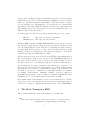
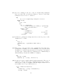
Figure 1:
4
An example of such a system is given in figure 1. This shows an IBM PCAT with an INMOS B004 evaluation board, running a single IMS T414
transputer and 2 megabytes of external ram. This transputer acts as the
host processor for the development of programs, and for loading multiple
transputer networks. Link 2 of the B004 is connected to an INMOS B003
evaluation board, which runs 4 IMS T414s, each with 256 kilobytes of memory.
Typically, when a PROGRAM is loaded onto a multiple transputer network,
a simple EXE program will also be run on the host transputer which monitors the output transmitted back from the PROGRAM, sends results to the
screen, passes on any input from the keyboard, and controls the TDS filing
system, as required.
A simple PROGRAM, intended to run on a network of just one transputer,
looks like this:
{{{ PROGRAM Example
{{{F
... SC Example
PROCESSOR 0 T4
Example ()
}}}
}}}
When this bundle is compiled, configured and extracted, a new fold is created:
...F CODE PROGRAM Example
If extracted as a BOOTABLE type fold (as opposed to a DIAGNOSTIC
fold), this CODE PROGRAM fold will just contain code which will initialise
and load a single transputer, and run SC Example. Thus, if an occam byte
array Program contains the contents of a bootable CODE PROGRAM fold,
then the effect of
ToLink ! Program
is to load and run the program on a transputer connected to link ToLink.
The precise way in which a transputer loads code does not concern us here
- it is described in full in [1].
A program may thus explore a network of transputers as follows:
5
Suppose that a transputer is already running an exploratory worm program,
and that it is connected to another transputer, which has not yet been loaded
with code. The first transputer, which will be called the ’parent’, loads the
second (’daughter’) by outputting the code Program as above. It then sends
Program a second-time, which the daughter stores as a byte array in memory.
The daughter is now also in a position to load other transputers, and so on,
until the entire network is loaded.
To achieve this, the exploratory worm program is made up of two parts:
...
...
EXE Host
- This runs on the host transputer
PROGRAM Worm - This explores the network
The Host EXE reads the CODE PROGRAM Worm fold, and stores it in a
byte array Program. After resetting the network, it then loads this program
onto the first transputer in the network by outputting Program on an appropriate link. As the worm proceeds to explore the network, the program
running on the host transputer processes any data returned to it from the
worm, interpreting and displaying the results.
The following section (section 3) describes the EXE program which runs on
the host transputer, while section 4 describes the PROGRAM which actually explores the network. Section 5 shows some typical results. Section 6
provides some notes on extending the exploratory worm for different uses.
In describing the program, declarations and channel protocols have been
left out, for brevity, except where they may not be obvious. Variable names
start with a lower case letter, constants with a capital. Tokens, indicated by
the suffix .t, are used to communicate a particular meaning on a channel,
for example, NoMoreData.t. Similarly, a suffix .v is used to indicate a
particular interpretation of a stored value, for example, assigning the value
UnAttached.v to a word which describes the status of a link.
It is assumed that each transputer can access enough memory to run the
exploratory worm - information about the memory requirements may be
obtained by creating a configuration information fold for the PROGRAM.
3
The Host Transputer EXE
The program which runs on the host transputer looks like this:
SEQ
code.fold.reader (Screen, from.user.filer[0], to.user.filer[0],
programTable, programLength, errorFlag)
6
IF
errorFlag
SKIP
TRUE
SEQ
... Determine which link to examine
... Reset subsystem, links
-- Main section
VAL Program IS [programTable FROM 0 FOR programLength]
PAR
WormHandler (LinkIn[linkNumber], LinkOut[linkNumber],
ToInterface, linkNumber, Delay, Program)
Interface (ToInterface, SoftScreen, Heading, linkNumber)
... Display and file output using standard procs
write.full.string (Screen, "*C*NType <any> to continue")
Keyboard ? word
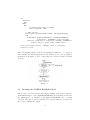
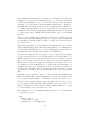
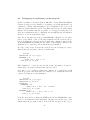
After determining which of the host transputer’s links is to be explored,
and resetting the subsystem network, the main section of the program is
structured as in figure 2. The components are described in the following
sections.
Figure 2:
3.1
Reading the CODE PROGRAM fold
The process code.fold.reader provided in the example exploratory worm program will attempt to read a CODE PROGRAM fold from inside a fold bundle, which may be a compiled or uncompiled PROGRAM fold, or a plain
text fold. The latter option is included for reasons which are described in
the section on filing the output.
7
The reading and writing of folds and files is described in [1] an error occurs,
the boolean errorFlag is set to TRUE, and the cause of the error is displayed
on channel Screen, using the term.p protocol.
3.2
Resetting the subsystem
It is assumed that the reset pins of the subsystem network are chained
together, and controlled by the host transputer (for example, the Subsystem
Reset pin on a B004, as described in [2]). In order to reset the transputers
correctly, the reset pin must be held high for a certain minimum period of
time - a millisecond is ample.
3.3
Determine which link to examine
The program asks the user which link of the host transputer, linkNumber,
is to be examined - the link which is connected to the subsystem must be
stated. None of the other links will be tried during the course of the program.
If two (or more) links are connected to the same subsystem, then only one
can be tried. In this case, the other link will receive data from the subsystem,
as the worm program explores, which remains unacknowledged. In order
that this does not upset any program running on the host transputer after
the exploratory worm has completed, all the links are reset on completion
of the program. The resetting of links is described in [3].
3.4
Worm handler
The channels LinkIn, LinkOut have been placed at the transputer’s hard
links. This process attempts to load a transputer connected to link linkNumber with the exploratory worm program. However, there may be nothing
connected at all, or the transputer connected may not have been reset, or
not powered on, or some other simple problem, in which case the output
will fail. To cater for this eventuality, the OutputOrFail routines described
in [3] are used. If the output of the code Program is not completed within
a period Delay, then it is abandoned, and the link is reset. This makes it
possible for the program to terminate neatly, even if there is no transputer
connected to the link.
If the code Program is successfully output from the link, booting a transputer, then PROC WormHandler sends more data, as described in section 4.3. In particular, this new transputer is given an identity number
’0’. As the exploration proceeds, PROC WormHandler relays data back
from the network to PROC Interface.
8
3.5
Interface
The Interface process is passed data from the worm handler. This is interpreted, and text is output on channel SoftScreen using the term.p protocol [1].
3.6
Display and file output
The output from PROC Interface is suitable for immediate display on the
screen. However, the standard library processes scrstream.fan.out and scrstream.to.file are used to file a copy of the output. To do this, the user
must transfer the CODE PROGRAM fold from the PROGRAM Worm fold
into an empty text fold. When the EXE is run, pointing at this text fold,
then a new, filed fold will be created which contains the output from PROC
Interface:
{{{ Results
...F CODE PROGRAM Worm
...F Output will appear here
}}}
write.endstream is used to close down these processes.
If the program is run while pointing at a PROGRAM fold, results are displayed but not filed.
4
The exploratory worm PROGRAM
4.1
Introduction
As described in section 2, the exploratory worm program is constructed as a
PROGRAM fold which consists of a separately compiled process, SC worm,
placed on a single transputer. This is then extracted to produce a CODE
PROGRAM Worm fold, which contains code to boot a transputer and run
SC Worm on that transputer. This section now describes how that SC is
constructed.
The exploratory worm is structured as follows
SEQ
...
...
Read in copy of program, identify boot link
Initialise
9
SEQ I = 0 FOR NLinks
... Try each link in turn
... Return control to parent
... Feed back final link information to parent
When SC Worm starts to run on a transputer, it first identifies which link
is connected to its parent, i.e. which of its neighbours booted it, and inputs
a copy of the program code so that it, too, may boot other transputers.
After initialising various flags (which keep track of which links have been
explored, etc.), the program now picks a link, and tries to send a probe down
the link, which may (or may not) be connected to another transputer. An
OutputOrFail routine is again used, and if the program does not receive any
response, it will timeout and look elsewhere.
The period of time for which program is prepared to wait, Delay, is quite
critical. It must be long enough for any neighbour to have the chance to
reply, but not so long that the program is slow to explore a large network of
transputers. A Delay of 30 milliseconds has been found to be appropriate.
Section 4.2 describes the way in which a transputer probes a link to test
whether a neighbouring transputer is attached. Section 4.3 describes how,
if this is successful, the program is loaded and run on the neighbour. These
are incorporated into the exploration worm in section 4.4, which describes
a simple algorithm for exploring a tree of transputers. In section 4.5, this
algorithm is generalised, to enable the exploration of a general network of
transputers.
4.2
Probing a neighbouring transputer
A transputer can conveniently test whether link I is attached to an unbooted
neighbouring transputer by using the Peek and Poke feature [4]. For example, it may load a word of data at an address, and then read it back, as
follows:
[4]CHAN OF ANY LinkIn, LinkOut :
PLACE LinkIn AT 4 :
PLACE LinkOut AT 0 :
SEQ
LinkIn[I] ! 0(BYTE); Address; Data
LinkIn[I] ! 1(BYTE); Address
LinkOut[I] ? word
10
-- Poke
-- Peek
-- Data is returned
Provided that the address specified exists in memory, then the word returned
should match the data sent. A suitable address is MinInt, the minimum 32bit integer, i.e. #80000000, the bottom of the neighbouring transputer’s
internal ram.
In practice, an OutputOrFail routine is used for peeking and poking, in case
the link is unattached. If successful, the Data is returned on hard channel
LinkIn[I]. Otherwise, (after a time Delay has elapsed,) the program assumes
that the link is unattached.
4.3
Booting a neighbouring transputer
Having determined that a link is connected to an unbooted neighbour, a
transputer loads a neighbouring, unbooted transputer by outputting the
code Program, as mentioned in section 2. The newly booted neighbour will
first read in a copy of the program, and identify the boot link:
SEQ
ALT I = 0 FOR 4
-- Determine which link is connected
-- to my parent!
LinkIn[I] ? programLength
parentLink := I
LinkIn[parentLink] ? [programTable FROM 0 FOR programLength]
LinkIn[parentLink] ? token; loadingData
loadingData[3] := parentLink
LinkOut[parentLink] ! LoadingData.t; loadingData
LinkIn[parentLink] ? token
-- Synchronise.t token from the host
The parent sends the length of the program, which enables the daughter
to determine which link is connected to the parent. The code Program is
sent again, and stored by the daughter as a byte array for future use. The
parent also sends a set of data which includes the parent identity number,
the link attached to the daughter, and the number of transputers found so
far, nTransputers. The daughter returns the data, with the link on which
the daughter was booted appended.
The data returned by the daughter is referred to as loadingData. loadingData contains information useful to follow the path of the worm. Its four
elements are, in order, the identity number of the parent, the link which
the parent used to boot the daughter, the identity number of the daughter,
and the link on which the daughter was booted. This array is transmitted
back to the host transputer for display. The WormHandler process, running
11
on the host, acknowledges receipt of the loadingData with a Synchronise.t
token, transmitted back to the new daughter.
4.4
Exploring a tree of transputers
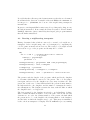
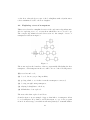
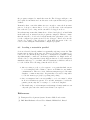
This section describes a simplified version of the exploration algorithm, suitable for exploring a tree, i.e. a network in which there are no closed loops.
The complete algorithm is described in section 4.5. An example of a tree of
transputers is shown in figure 3.
Figure 3:
The worm explores the branches of the tree sequentially. Excluding the host
transputer, each transputer in the tree will be in one of the following states:
(R) reset but unbooted;
(0) booted, but not yet probing its links;
(1) probing a link, to see if there is another transputer connected;
(2) booting a neighbouring transputer;
(3) relaying loadingData to the host;
(4) all links have been explored.
The network is then explored as follows
Consider figure 3 as an example. Suppose that link 3 of transputer A has
booted transputer B by link 0, and B has input a copy of the program
from A. A enters stage 3, in which it will wait passively to transmit further
12
data. Transputer B starts stage 1, probing one of its links to see if any other
transputer is connected. Since link 0 is known to be connected to transputer
A, link 1 is the first link to be probed. As described in section 4.1, the nucleus
attempts to poke and then peek any transputer which may be attached to
that link. The nucleus then waits for a word (which should be MinInt), to
be returned on input link 0, for a period of time, Delay, before timing out. If
nothing is returned, the program assumes this link is unattached, and sets a
boolean downLoad[0] to FALSE. The next link, link 2, is probed in a similar
manner.
However, let us assume that a transputer is attached to link 1, and that
it has returned the value MinInt in response to the probing. Transputer B
now attempts to load the neighbour with code (stage 2), as described in the
previous section.
Call this new daughter ’C’. C determines its parentLink, the code Program,
and loadingData (stage 0). It takes its identity number to be nTransputers,
and increments nTransputers by one, where nTransputers is the number of
transputers found so far (the third element of loadingData).
At this point, transputer B enters stage 3 of the program, and acts simply
to pass on messages from C, even though it has not yet checked links 2 or 3.
While transputer C explores its environment, B does not attempt to timeout
link 1. Let us suppose that C is not connected to any other transputers.
Having failed to find any neighbours, transputer C returns control to B,
by sending the token ReturnControl.t, together with the latest number of
transputers found so far. Transputer C then enters stage 4, and since it
has tried all of its links, takes no further part in the exploration. B sets
downLoad[1] to TRUE, to note that a transputer has been loaded from this
link.
Transputer B now returns to stage 1 of the program, and similarly tries
link 2, and finally link 3. When all links have been tried, B returns control
to A, together with the number of transputers found so far. And so on ...
Because of the sequential nature of the algorithm, there is only ever one
process actively testing its links. That transputer alone stores the correct
value of nTransputers. This enables a unique identity number to be given
to each transputer as the exploration proceeds.
If a transputer is booted on link parentLink, then the above algorithm may
be expressed as follows :
SEQ
SEQ I = 0 FOR 4
downLoad[I] := FALSE
nTransputers := LoadingData[2]
13
id
:= nTransputers
nTransputers := nTransputers + 1
SEQ I = 0 FOR 4
-- Try each link in turn
IF
I = parentLink
SKIP
TRUE
SEQ
stage
:= 1
waiting := FALSE
badOut := FALSE
... Probe neighbouring transputer (set waiting)
(i)
... Boot neighbour, and wait while worm explores (iii)
LinkOut[parentLink] ! ReturnControl.t; nTransputers
Note:
(i) Peek and poke a neighbour:
SEQ
OutputToken.t
OutputInt.t
OutputInt.t
OutputToken.t
OutputInt.t
(LinkOut[I],
(LinkOut[I],
(LinkOut[I],
(LinkOut[I],
(LinkOut[I],
0(BYTE),
MinInt,
MinInt,
1(BYTE),
MinInt,
Delay,
Delay,
Delay,
Delay,
Delay,
badOut) -- (ii)
badOut)
badOut)
badOut)
badOut)
Clock ? time
ALT
LinkIn[I] ? token -- Value returned
SEQ
stage := 2
waiting := TRUE
Clock ? AFTER time PLUS Delay
SKIP
Note how the return of the value MinInt indicates that a successful
poke and peek has taken place (the boolean badOut also indicates that
this transputer has output the peek and poke). waiting is now set to
true, and the algorithm enters the next loop.
(ii) The procs OutputToken.t, OutputInt.t, OutputString.t are based on
the output or fail routine. For example:
PROC OutputToken.t (CHAN OF ANY ToLink, VAL BYTE Token,
VAL INT Delay, BOOL stopping)
INT time :
14
TIMER Clock :
VAL [1]BYTE String RETYPES Token :
IF
stopping
SKIP
TRUE
SEQ
Clock ? time
time := time PLUS Delay
OutputOrFail.t (ToLink, String, Clock, time, stopping)
:
(iii) Given the success of (i) (waiting is set to TRUE), now try to boot the
neighbouring transputer:
SEQ
...
Try to boot neighbouring transputer
WHILE waiting
-- worm explores branch off neighbour
LinkIn[I] ? token
CASE token
... LoadingData.t
(iv)
... ReturnControl.t
(v)
Booting is performed as follows:
VAL []BYTE InitialData RETYPES [Id, I, nTransputers, 0] :
VAL Program IS [programTable FROM 0 FOR programLength] :
SEQ
OutputString.t (LinkOut[I],
Program, Delay, badOut)
OutputInt.t
(LinkOut[I], SIZE Program, Delay, badOut)
OutputString.t (LinkOut[I],
Program, Delay, badOut)
OutputInt.t
(LinkOut[I], LoadingData.t, Delay, badOut)
OutputString.t (LinkOut[I], InitialData,
Delay, badOut)
Although we know, from peeking and poking, that there is a transputer
waiting to be booted off this link, it helps debugging to use the output
or fail routines again here!
(iv) The loadingData is returned to the host (for immediate display) and is
acknowledged by the token Synchronise.t. On receipt of the data, the
host process returns the token Synchronise.t. This synchronisation is
important, for it guarantees that all transputers at stage 3 are ready
to be probed on any link J, and are not still engaged in returning
loadingData.
LoadingData.t
15
[LoadingDataLength]INT passOnData :
SEQ
LinkIn[I]
? passOnData
LinkOut[parentLink] ! LoadingData.t; passOnData
LinkIn[parentLink] ? token
-- Synchronise.t
LinkOut[I]
! Synchronise.t
stage := 3
(v) The return of control indicates that the tree off link I has been completely explored. This process may now explore other links.
ReturnControl.t
SEQ
LinkIn[I] ? nTransputers
downLoad[I] := TRUE
waiting := FALSE
Error reporting will be described in the next section.
The searching procedure is initiated by PROC WormHandler booting the
first transputer in the tree, and telling it that nTransputers = 0. When
that transputer finally returns control to WormHandler, the total number
of transputers in the network will be returned, and the network will have
been completely searched.
4.5
Exploring a general network of transputers
The algorithm described in the previous section would be quite satisfactory
if all networks took the form of a tree. However, they are usually more
complicated, in that they may have either or both (i) two links connected on
the same transputer, and (ii) there are closed loops of connections involving
more than one transputer. The network will still have a unique start point,
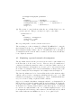
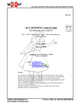
however, namely the host transputer. An example is shown in figure 4.
The basic algorithm is as before, but in addition there is the situation where
a link is connected back to a transputer which has already been booted. This
is handled by arranging for every transputer to ’listen’ on all links which have
not yet been tried - using a replicated ALT construct.
Suppose, for example, that link 2 of transputer A has booted transputer B on
link 0, and is now passively waiting while B explores further. B outputs the
poke and peek sequence on link 1, which arrives back at link 1 of transputer
A. It must now be arranged that A will recognise this sequence, even though
it comes in on a different link to the one on which daughter B was booted.
So A inputs the whole message, and returns a token AlreadyLoaded.t, which
has a value different from MinInt, in order to be recognised by B.
16
Figure 4:
In order that A does not try link 1 again later, a boolean tryLink[I] is
maintained (initialised to true), indicating whether to try probing off link I.
In our example, tryLink[1] is set to FALSE.
It is also useful at this stage to build up a map of which links are connected
to whom. A table, [4][2]INT linkArray, is assembled for each transputer, in
which each link has a corresponding entry giving the identity of the neighbour attached to that link (if any), and that neighbour’s link. For example,
linkArray[3] := [6,0]
would be set to indicate that link 3 is connected to link 0 of transputer 6.
When a parent boots a daughter, this information is communicated in the
loadingData, and may be entered into the table as appropriate. However,
when a transputer probes another one which is already loaded, the programs
running on each transputer must exchange identities and link numbers, storing the information in linkArray.
The central part of the program now looks like this:
SEQ
... Initialise downLoad, id, nTransputers as before
...
Initialise tryLink, linkArray
SEQ I = 0 FOR 4
IF
NOT tryLink[I]
SKIP
TRUE
... Abbreviations as before
SEQ
... Initialise as before
... Probe neighbour
... Boot neighbour, and wait for reply
17
(i)
(ii)
(iv)
tryLink[I] := FALSE
LinkOut[parentLink] ! ReturnControl.t; nTransputers
Note:
(i) Initialise tryLink[I] to TRUE for all links except the link back to parent.
The elements 0 and 1 of the array loadingData contain the identity
and link of the parent transputer.
SEQ I = 0 FOR 4
tryLink(I] := TRUE
tryLink[parentLink] := FALSE
linkArray[parentLink] := [loadingData FROM 0 FOR 2]
(ii) There is now the possibility that two links on the same transputer are
connected. Hence, the peek and poke must be done in parallel to
listening on all other links:
PAR
... Probe neighbouring transputer
SEQ
Clock ? time
ALT
ALT J = 0 FOR NLinks
(J <> I) AND tryLink[J] & LinkIn[J] ? probeString
SEQ
linkArray[J] := [id, I]
linkArray[I] := [id, J]
tryLink[J] := FALSE
LinkIn[I] ? token
CASE token
... MinInt as before
... AlreadyLoaded
(iii)
... ELSE -- error
(vi)
... Time out as before
(iii) If there is a closed loop (other than 2 links connected on the same
transputer), we get the situation that one transputer probes another,
which replies AlreadyLoaded.t. The two ends then exchange pleasantries, viz id and link.
PAR
LinkOut[link] ! [id, link]
LinkIn[link] ? linkArray[link]
18
(iv) As before, waiting is only set to true if a neighbouring transputer
has been found. The case when two links are connected on the same
transputer need not now be considered:
SEQ
... Try to boot neighbouring transputer as before
WHILE waiting
SEQ
Clock ? time
ALT
ALT J = 0 FOR NLinks
(J <> I) AND tryLink[J] & LinkIn[J] ? probeString
... Reply ’AlreadyLoaded.t’
(iii)
LinkIn ? token
CASE token
... LoadingData.t
(v)
... ReturnControl.t
(as before)
... ELSE -- error
(vi)
... Time Out
(vii)
(v) In addition to passing the loading data back, we also keep a note of the
daughters id, boot link:
IF
stage = 2
linkArray[I] := [passOnData FROM 2 FOR 2]
TRUE
SKIP
(vi) Make a note of the fact that a bad communication has taken place
on this link by making a record in linkArray. Use a special token
TokenError.v to indicate that an unexpected token has been returned.
A classic cause of this is when two transputers are communicating at
different link speeds (10 and 20 MHz, for example).
SEQ
waiting := FALSE
linkArray [I] := [stage, Token rror.v]
(vii) A timeout at stage 1 implies that the link is unattached. However, if
a timeout occurs at a later stage, assuming Delay is long enough to
allow for the booting of a daughter, then the neighbour has not been
successfully loaded - report this as an error.
Clock ? AFTER time PLUS Delay
SEQ
linkArray[I] := [stage, TimeOutError.v]
waiting := FALSE
19
4.6
Returning the local link map
Having explored the local connections of each link on a transputer, and
returned control to the parent, we wish to relay the information linkArray
back to the host transputer. This is done as follows:
CHAN OF ANY ToParent IS LinkOut[parentLink] :
SEQ
stage := 4
ToParent ! NetworkData.t; id; linkArray
SEQ I = 0 FOR 4
IF
NOT downLoad[I]
SKIP
downLoad[I] -- Pass on network info from daughter processes
SEQ
reading := TRUE
WHILE reading
SEQ
LinkIn[I] ? token
CASE token
... NetworkData.t
(i)
... NoMoreData.t
(ii)
... ELSE
(iii)
ToParent ! NoMoreData.t
Note:
(i) Pass on the identity and link array.
NetworkData.t
-- pass on id and info
INT passOnId :
[4][2]INT passOnLinkArray :
SEQ
LinkIn[I] ? passOnId; passOnLinkArray
ToParent ! NetworkData.t; passOnId; passOnLinkArray
(ii) There is no more data to transmit from this branch.
NoMoreData.t
reading := FALSE
(iii) This is an error. Return a modified linkArray report.
20
ELSE
SEQ
reading := FALSE
linkArray[I] := [stage, TokenError.v]
ToParent ! NetworkData.t; id; linkArray
Data from each transputer, giving the id. number and local link connections,
will arrive back at WormHandler after the entire network has been loaded.
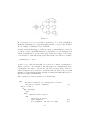
5
An example
Below is some typical output from an exploratory worm program when run
on the transputer configuration shown in figure 5:
Figure 5:
Checking network off link 2 ...
Parent
Id Link
host
2
0
1
1
1
1
3
3
2
4
3
5
0
Daughter
Id Link
0
0
1
0
2
1
3
1
4
0
5
1
6
2
The number of transputers found is 7
Arranged in the following network :
Id
0
1
Link: 0
host-2
0-1
1
1-0
2-1
2
3-0
2-0
21
3
6-0
3-1
2
3
4
5
6
1-2
0-2
3-2
6-2
0-3
1-1
1-3
ooo
4-3
3-3
ooo
4-0
ooo
5-3
5-0
ooo
6-1
5-1
5-2
ooo
The first table refers to the initial loading of the network. It indicates that
link 2 of the host transputer (running on a B004, for example) has booted
transputer 0 by link 0. Then link 1 of transputer 0 booted transputer 1 by
link 0, and so on.
The second table summarises the connectivity of the network, by stating
what each link of each transputer is attached to. For example, the entry 6-0
in row 0, column 3, indicates that link 3 of transputer 0 is attached to link 0
of transputer 6.
6
Some points to note
This section will note some further developments which can be made to an
exploratory worm program, and restrictions on such a program.
6.1
16 and 32-Bit compatible programs
The instruction set of the INMOS transputer is independent of the wordlength
of the transputer on which it is to run. Code compiled for the IMS T414
may be run on a T800, or T212, for example, provided the following points
are observed:
1. If data, for example text strings or constant definitions, is included in
the program, then it will be ’word aligned’ in the compiled code. A
program containing such data, and compiled for a 32-bit transputer
(’T4’), will run on a 16-bit transputer (T2’), but the converse may not
be true. Therefore, it will be assumed that programs intended to run
on either a T2 or T4 are compiled using the T4 compiler.
2. Communication between two transputers with different word lengths
requires a mutually agreed datalength. For example, it might be arranged that all data is input and output as INT16 words, and that
linkArray is built up and transmitted as an INT16 array.
Internal communication of words should be treated similarly. For example, the input of a word, when compiled for a 32-bit machine, always
22
attempts to input explicitly 4 bytes - which is not what is wanted if
the program is to be run on a 16-bit machine.
Beware that, if INT32 words are specified in a program which is compiled for a 32-bit transputer, they will be recognised as being of the
natural wordlength of the machine, and no special treatment will be
given. If the same code is run on a 16-bit machine without recompilation, the data would be treated as 16-bits, which would be catastrophic
if it was intended to communicate a 32-bit word.
3. Peeking and poking of a transputer assumes knowledge of the wordlength
of that device. But when a transputer first explores its links, it knows
nothing about what is connected at the other end! The simplest way
around this is to attempt to poke and peek a neighbour assuming that
it is a T2. If this fails, terminate the T2 sequence with an extra byte
to make it look like a T4 poke. Then try again for a T4. For example:
ToLink ! #00;
#01;
ToLink ! #00
ToLink ! #00;
#01;
#00; #80; #00; #80;
#00; #80
-(i)
-- (ii)
#00; #00; #00; #80; #00; #00; #00; #80;
#00; #00; #00; #80
-- (iii)
(i) is a sequence for poking and peeking a 16-bit transputer, (ii) rounds
this off to a valid 32-bit poke (but at an address in external memory,
which is not guaranteed to exist) and (iii) is a sequence for poking
and peeking a 32-bit transputer. Words have been expressed as bytes,
little end first, to prevent any possible confusion over compiling 16 and
32-bit words. If the neighbour is already loaded, it should be made to
reply immediately it receives probe (i).
4. The memory requirement of programs is determined by the compiler
as the number of words needed. However, running a program on a
16-bit transputer may require more words of storage than if the same
program was run on a 32-bit transputer. For example, [4] BYTE
array requires 1 word of storage on a T4, but 2 words on a T2. Since,
as is noted in (1) above, the program must be compiled for a 32-bit
transputer, the allocation of storage must be forced to be suitable for
16-bit transputers by declaring arrays as follows:
[2][ArraySize]BYTE dummyArray :
[ArraySize]BYTE array IS dummyArray[0] :
The same applies for boolean and INT16 arrays.
23
5. Provided that it does not contain any floating point or extended arithmetic, a program compiled and extracted for a T414 will run on a T800.
The reverse is not true - do not try to run a program compiled for the
T800 on a T414.
6. The code which loads a CODE PROGRAM fold onto a transputer
is wordlength independent, and a program compiled and extracted to
load a T4 will work equally well on a T2, provided that the above
points have been noted.
7. Because of differences in code placement, the debugger won’t work
when the worm is running on a transputer other than the one it was
compiled for.
6.2
Using an exploratory worm program to perform testing
An exploratory worm program is an extremely useful vehicle for testing
transputer based products. Tests for memory and the links may be included
in the basic program, for example. If a hardware fault occurs, the program
may report the location and nature of the problem, while continuing to
test other components in the network. This is particularly useful during a
long burn-in run. By testing the network repeatedly with an exploratory
worm, any failure may be detected and logged, while the rest of the network
continues to be burnt-in.
All INMOS transputers and transputer evaluation boards are burnt-in before
shipping, and subsequent failure is unlikely. However, this technique may
be useful for testing products which use transputers as components. In
designing an exploratory test program, the following points should be borne
in mind:
1. The same program will be loaded onto every transputer. Ideally, all
components of the network to be tested will be identical, but if there
is any variation, the program will have to dynamically assess the attributes (for example memory size, peripherals) of each transputer it
finds.
2. The program has its own algorithm for assigning identity numbers to
each transputer in the network, which may be quite different to the
one which the user has in mind. If a failure occurs, and the program is
run again, yet another different numbering of the network may occur.
3. If memory is to be tested, a transputer should test a section of memory of a potential daughter using peek and poke, before booting that
24
daughter. The section tested is the area where the program and
workspace will go.
4. If the links are to be tested, it should be remembered that corruption
of data on a link (by noise, for example) might cause a data packet to
look like an acknowledge, or vice-versa. The OutputOrFail -predefines
are useful in this context.
6.3
Using an exploratory worm program to load another program
Another field in which it is useful to have a vehicle to load an arbitrary
network is when the user intends to run a program replicated over an array
of processors, but does not care too much about their precise configuration.
An example of this is the data farm approach to processing [5]. In this, one
central processor ’farms out’ work to an array of ’worker’ processes, each of
which is capable of processing a piece of data and returning it. The following
points should be made:
1. The program which the user wishes to run on every transputer is included as part of the SC Worm, so that it executes after the exploration
phase has been completed.
2. An identical program will run on each transputer in the network. This
program will be passed information by the exploratory worm such
as which links are connected to neighbours, and which is connected
back to the parent. From such information, algorithms to control the
broadcasting or routing of data may be developed.
3. The host transputer will be responsible for communicating with the
rest of the network as required, for example by sending out data for
processing, and receiving results back.
4. Although this technical note has described an exploratory worm as
being initiated from the host transputer, there is no reason why it
could not be launched out from an already partially loaded system.
A more flexible system can be constructed by arranging that the worm
declares a large workspace. After the system has been explored, the host
sends out processes, in the form of pieces of compiled code, to specified
processors in the network, which are run using KERNEL. RUN. This allows
the placement of code to be decided at run-time, which might be useful,
for example, in constructing a program which takes advantage of all the
processors in an arbitrary network, or to be used as a basis for a multitasking operating system.
25
6.4
Debugging an exploratory worm program
By its very nature, a worm program is difficult to debug. While the INMOS
software debugger is very useful for debugging a program which has been
configured to match a known multiprocessor configuration, it does not deal
with a program which has explored an unknown network. To make things
simpler, let us assume that the program to be debugged is being run on a
network of transputers whose configuration is actually known, and which is
known to be free from hardware bugs.
Since the worm takes the form of a PROGRAM configured for one transputer, a bug which occurs on the first transputer in the network can be
traced by using the debugger in the normal way - simply point it at the
worm PROGRAM and it will give the values of all variables, channel communication, etc., and the point at which the program failed.
If a bug occurs deeper down in the network, use the following procedure.
First modify the program so that it looks like this:
... SC Worm
CHAN OF ANY a,b,c,d,e,f,g,h :
PROCESSOR 0 T4
... PLACE a AT 0, b AT 1, etc.
Worm (a,b,c,d,e,f,g,h)
(The channels a, ... h are not used by the worm, but must be declared to
ensure that code is placed in the same way as below.)
Now take a copy of this program, and configure it to match the actual
network (or part of the network). For example, for a 2 transputer network
connected by link 0 on each transputer:
... SC Worm
CHAN OF ANY a,b,c,d,e,f,g,h :
CHAN OF ANY i,j,k,1,m,n :
PLACED PAR
PROCESSOR 0 T4
... PLACE a AT 0, b AT 1, etc. as before
Worm (a,b,c,d,e,f,g,h)
PROCESSOR 1 T4
... PLACE e AT 0, a AT 4, i AT 1, etc.
Worm (e,i,j,k,a,l,m,n)
Load the network by pointing the EXE at the Worm PROGRAM configured for one transputer, in the usual way. (A suspected software bug occurs
which causes the program to fail...) Now point the debugger at the copy of
26
the program configured to match the network. The debugger will give complete symbolic information about the state of the system when the program
crashed.
Remember that, even if the failure is severe enough to cause the host transputer to lock up, so that it has to be rebooted, the state of the subsystem
is not altered by rebooting, and it can still be debugged as above
It is always important that channels are declared and placed on hard links
in the same way, no matter how the program is configured. This is to ensure
that the way the code is loaded exactly matches the placement of the code
for the configured program, as used by the debugger. If in doubt, use the
’check code’ feature of the debugger to check that placement of the code
loaded on the transputer matches the configured program.
6.5
Loading a network in parallel
Section 4 described an algorithm for sequentially exploring a network. This
is quite fast enough for most purposes. However, if a large program is to be
loaded onto an extremely large network o f transputers, a parallel loading
algorithm might be considered. Such an algorithm is not so simple as the one
described above. In particular, it may happen that two loaded transputers
simultaneously try to boot a third, unloaded transputer, which is connected
to both of them. The following points should be noted:
1. After receiving a peek or poke sequence on a particular link, an unbooted transputer will continue to listen on all links for any further
communication. Therefore, if two different transputers probe the same
daughter, confusion may arise. In particular, it would be impossible
to test the memory properly by peeking and poking.
2. Once a transputer has been successfully booted, care must be taken
in how it identifies its parent. For another transputer, besides the
genuine parent, may also be trying to boot the new daughter.
3. The numbering of each transputer with unique identity numbers can
only take place after the entire network has been explored.
References
[1] Transputer Development System, Prentice Hall, London 1988
[2] IMS B004 Evaluation Board User Manual, INMOS Ltd, Bristol
27
[3] Extraordinary use of transputer links, Technical note 1, INMOS Ltd,
Bristol 1987
[4] Transputer Reference Manual, Prentice Hall, London 1988
[5] Communicating Process Computers, Technical note 22, INMOS Ltd,
Bristol 1987
28