1
Copeland Scroll Fusion Compressor
TM
for refrigeration applications
User Manual
About Emerson Climate Technologies
Emerson Climate Technologies, a business segment of EmersonTM, is the world’s leading provider of heating, airconditioning and refrigeration solutions for residential, industrial, and commercial applications. It combines best-in-class
technology with proven engineering, design, distribution, educational and monitoring services to provide customized,
integrated climate-control solutions for customers worldwide. Emerson Climate Technologies’ innovative solutions,
which include industry-leading brand Copeland Scroll™, improve human comfort, safeguard food and protect the
environment. For more information, visit EmersonClimateAsia.com.
Leading Innovation in Scroll Semi-Hermetic Technology
Emerson realized an increasing need for a versatile, reliable, quiet, lightweight, serviceable compressor for the Cold Room
market and set out to develop a solution for this need. In the development process, the company brought together
70 years of semi-hermetic compressor expertise and 25 years of leadership in scroll technology. What came out of
this endeavor is the newly-designed Copeland Scroll Fusion compressor which combines Emerson’s revolutionary scroll
technology along with the serviceability of a traditional semi-hermetic compressor.
Our Vision:
Emerson Climate Technologies, With Our Partners,
Will Provide Global Solutions To Improve Human Comfort,
Safeguard Food And Protect The Environment.
2
Table of Contents
Safety Information
04
Features and Benefits
05
Nomenclature
05
Operating Envelopes
06
Technical Data
07
Dimensional Drawings
10
Wiring Diagram
14
Contact Lists
24
3
Safety Information
CopelandTM brand products semi-hermetic compressors are manufactured according to international safety standards.
Particular emphasis has been placed on the user’s safety. This user manual should be retained throughout the lifetime
of the compressor.
Safety instructions must be followed by all users before compressor operation. Only qualified and authorized personnel
are permitted to do installation, commissioning and repairing of this compressor. Electrical connections must be made
by qualified electrical personnel.
ICON DEFINITION
CAUTION
This icon indicates
instructions to avoid
property damage and
possible personal injury.
WARNING
This icon indicates
instructions to avoid
personal injury and
material damage.
ELECTRICAL SHOCK
This icon indicates
operations with a danger
of electric shock.
Caution
• Make sure that the compressor is upright and there are
no collisions or tilting during transit.
• Use only refrigerants and oils approved by Emerson.
• Make sure that the supply power, voltage, frequency
and phase are exactly as per the specifications on the
compressor nameplate.
• The dry air inside the compressor should be evacuated
before installation. The compressor comes charged
with dry air at a pressure of 2.0 bar.
Do Not:
• Use the compressor to de-pressurize (to evacuate) a
refrigeration system.
• Start the compressor when it is under vacuum.
• Conduct a test without connecting the compressor to
a system.
• Start the compressor without a refrigerant charge.
• Operate a compressor beyond its approved application
envelope.
• Touch the compressor or pipes when the compressor
is running. High/low temperature may cause burns/
frostbite.
• Release refrigerant into the environment without using
appropriate refrigerant recovery unit and methods
when removing refrigerant from the system.
Warning
• When operating the compressor or checking a
refrigeration system leakage, do not exceed operating
pressures out of the application envelope.
4
• Do not run the compressor with air. When operating
with air, the diesel effect may occur – i.e. the air sucked
in may mix with oil and gas. Such a mixture could
explode due to high temperature in the scroll discharge
port and thereby destroy the compressor and cause
injury or death.
• Open the discharge and suction shut-off valve before
starting the compressor. It is of vital importance that
the discharge shut-off valve is fully opened before the
compressor is started. If the discharge valve is closed or
partly-closed, an unacceptable pressure accompanied
by a proportionately high temperature will develop.
• All local safety regulations must be observed.
Electrical Shock
• Turn off electrical supply and power before servicing.
• Use this equipment only in a grounded system.
• Refer to the applicable system-wiring diagram as shown
in this manual.
Use Personal Safety Equipment
• The new compressor contains oil and dry air under a
pressure of 2.0 bar. While releasing pressure before
installation, the oil drain plug may pop out under
pressure and oil could spurt out.
• Safety gloves, protective clothing, safety boots and
protective eyewear should be worn where necessary.
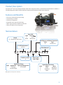
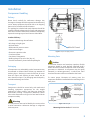
Product Description
Copeland ScrollTM Fusion was crafted specifically to adhere to the refrigeration industry’s need for field serviceable solutions. In addition, it
is specially designed for medium and low temperature refrigeration with the ability to handle various refrigerants.
Features and Benefits
• Emerson’s Copeland Scroll technology
• Serviceability in the field
• CoreSense™ Diagnostics
• Integrated vapor injection technology
• Wide range envelope and efficient operation
• Ability to handle various refrigerants
Nomenclature
Family
Q – Copeland Scroll Fusion
Type of Oil
Code
Description
E
POE
Blank
Mineral Oil
Intelligence and Motor Protection
Code
Type
W
CoreSense™
Scroll Displacement
(cc/rev)
Bill of Material
Q F 1 8 5 A E-T W D-2 0 2
Model Variation
A
Code
F
Application Range
Application Approved Refrigerants
Full Range
R22/R404A
Low/Med/High
Motor Types
Code Phase
T
3
Code
D
5
7
Typical Electrical Codes
60 Hz
50 Hz
460-3
380/420-3
200/230-3
200/220-3
380-3
–
Note: QF205 has low temperature model only.
5
Operating Envelopes
R22/R404A
60
70
50
60
40
o
-12oC Medium
-12Temperature
C Medium Temperature
Showcase Showcase
o
-7oC Medium-7Temperature
C Medium Temperature
Cold Room Cold Room
o
o
CondensingCondensing
Temperature
Temperature
C
C
70
-25oC Low Temperature
-25oC Low Temperature
Cold Room Cold Room
-32oC Low Temperature
-32oC Low Temperature
Showcase Showcase
QF115/QF125/QF145/QF175/QF185
R22
R404A
R22
R404A
50
30
40
20
30
10
20
0
10
-50
-40
-30
-20
-10
0
10
20
0
10
20
0
10
20
0
10
20
Evaporating TemperatureoC
o
Note:
0 20 C Return Gas Temperature. No Fan Cooling
-50
R22/R404A
-40
-30
-20
-10
Evaporating TemperatureoC
o
o
CondensingCondensing
Temperature
Temperature
C
C
70
60
-25oC Low Temperature
-25oC Low Temperature
Cold Room Cold Room
-32oC Low Temperature
-32oC Low Temperature
Showcase Showcase
Note: 20oC Return Gas Temperature. No Fan Cooling
QF205
R22 / R404A
70
50
60
40
R22 / R404A
50
30
40
20
30
10
20
0
10
-50
-40
-30
-20
-10
Evaporating Temperature C
o
Note:
0 20oC Return Gas Temperature. No Fan Cooling
-50
-40
-30
-20
-10
Evaporating TemperatureoC
Note: 20oC Return Gas Temperature. No Fan Cooling
6
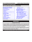
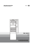
Nameplate Information
Figure 1. Nameplate and nameplate location
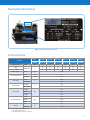
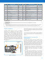
Technical Data
Model
Displacement
MOC
LRA
50 Hz
R22
QF115A
QF125A
QF145A
QF175A
QF185A
QF205A
R404A
QF115AE
QF125AE
QF145AE
QF175AE
QF185AE
QF205AE
m /h
19.3
21.1
23.5
26.4
30.4
36.9
24
25
27
32
33
25
80
80
80
105
105
105
3
1
2
Motor Speed
Crankcase Heater
Oil Charge
Service Valves
TWD 50 Hz
A
50 Hz
rpm
2,900
Power
W
60
Voltage
V
220
Initial
Recharge
Suction
Discharge
L
in
Length
Dimensions
Base Mounting
Width
2.54
1-1/8
1
675
mm
355
Height
389
Length
350
Width
mm
Bolt
Weight
2.66
Net
Gross
200
M10
kg
130
140
Notes: 1. MOC: Maximum Operating Current
2. LRA: Locked Rotor Current
3. QF205AE has low temperature model only
7
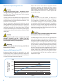
Maximum Operating Pressures
Caution
A high-pressure control with a maximum cut-out
setting of 28 bar(g) is required. The high-pressure cutout should have a manual reset feature for the highest
level of system protection.
The low-pressure cut-out should be set as high as possible in
all applications. For medium temperature applications, the
normal minimum is 2.5 bar(g) which corresponds to -10oC
for R22 and -16oC for R404A.
For low temperature applications the minimum cut-out
setting should not be lower than 0.3 bar(g) for a compressor
using R404A, and should not be lower than 0.1 bar(g) for a
compressor using R22. The cut-out point of the LP switch
must be calibrated using an accurate suction pressure gauge
rather than the scale on the switch which is provided for rough
setting only.
Mineral oils such as Suniso 3GS are approved for R22
application. Operation with R404A and R507 requires
Polyol Ester (POE) lubricants, and POE oil models are filled
with Emkarate RL 32-3MAF ex-factory. Emkarate RL 323MAF and Mobil EAL Arctic 22 CC are both approved for
top up and servicing.
Caution
Do not mix ester oils with mineral oil and/or alkyl
benzene when using chlorine-free (HFC) refrigerants.
The compressor is supplied with an initial oil charge.
The standard oil charge for use with refrigerant R404A
is a polyolester (POE) lubricant Emkarate RL 32-3MAF. In
the field, the oil level could be topped up with Mobil EAL
Arctic 22 CC if 3MAF is not available. See nameplate for
original oil charge in litres. A field recharge is from 50-100
ml less than the original charge.
Caution
Oil must be drained from both the high and low sides of
the compressor whenever oil is changed.
Caution
The Copeland Scroll™ Fusion compressor should
NEVER be allowed to run in a vacuum. The lowpressure cut-out should have a manual reset feature
for the highest level of system protection.
Warning
The maximum pressure for leak testing should be no
higher than 22.5 bar(g).
Approved Refrigerants and Oil
Refrigerants R404A and R22 are approved for use with
Copeland Scroll Fusion. Application with other refrigerants
may be possible in special cases. Please contact an Emerson
Climate Technologies Application Engineer.
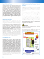
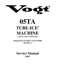
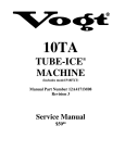
One disadvantage of POE is that it is far more hygroscopic than
mineral oil (see Figure 2). Brief exposure to ambient air causes
POE to absorb sufficient moisture to make it unfit for use in a
refrigeration system. Since POE holds moisture more readily
than mineral oil, it is more difficult to remove it through the
use of a vacuum. Compressors supplied by Emerson Climate
Technologies contain oil with low moisture content, and
this may rise during the system assembling process. POE oil
should not be exposed to the atmosphere for longer than 15
minutes. A filter drier is installed to help maintain moisture
level in the oil less than 50 ppm. If oil is charged into a system,
it is recommended to use POE with a moisture content no
higher than 50 ppm.
Moisture Absorption
@ 25oC & 50% RH
PPM
1500
POE
1000
500
Mineral Oil
50
100
150
200
250
300
hours
Figure 2. Absorption of moisture in ester oil in comparison to mineral oil in ppm by weight at 25°C and 50% relative humidity.
8
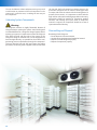
Installation
Compressor Handling
Delivery
Please check carefully for unforeseen damage. Any
shortage or damage should be reported to the delivering
carrier. Heavy equipment should be left on its shipping
base until it is moved to the final location.
The packing list included with each shipment should be
carefully checked to determine if all parts and equipment
have been received. Deficiencies should be immediately
reported in writing to your local Emerson Sales Office.
Lifting eye
Standard delivery
•Suction and discharge shut-off valves
•Oil charge, oil sight glass
•Oil level switch
•Differential oil pressure sensor
•Plate heat exchanger
•Electronic expansion valve
•Crankcase heater
•CoreSense™ Diagnostics
•Holding charge of up to 2.0 bar (dry air)
•For other accessories, please check the packing list
Packaging
All compressors are individually packed. Accessories may
be mounted or delivered loose. Please pay attention to
stacking layers. Stacking in transit should not be more
than two layers and stacking in-store should not be
more than three layers. The packaging must be kept dry
and without damage at all times.
M16x2.0 Thread
Figure 3. Compressor lifting method
Mounting Parts
Caution
To minimize vibration and start/stop impulses, flexible
mountings should be used. Because Copeland Scroll™
Fusion has scroll hermetic compressor level of vibration,
grommets are delivered. A compressor may be rigidly
mounted (i.e. without grommet) - in which case, more
shock and vibration will be transmitted to the frame.
To ensure proper lubrication of moving parts, the
compressor should be installed with four mountings in the
same plane.
Transport
Compressors should be moved only with mechanical
handling equipment appropriate for the weight
involved. For safety reasons, one lifting eye should be
fitted before moving a compressor (M16x2.0). Please
refer to the illustrations on Figure 3 to see how to lift the
compressor safely.
Warning
The compressors must not be lifted by the service valves
or other accessories. Otherwise damage or refrigerant
leaks may occur.
Figure 4. Mounting Kit
Mounting Kit Part Code: 027-0443-00
9
Piping Connection and Compressor
Installation
Brazing
{
Area Area Area
3
2
1
{
•It is important to flow nitrogen through the system
while brazing all joints during the system assembly
process. Nitrogen displaces the air and prevents the
formation of copper oxides in the system.
•Recommended brazing materials: any material is
recommended, preferably with a minimum of 45%
silver.
•Be sure valves I.D. and connecting tube O.D. are
clean prior to assembly. If oil film is present, wipe with
denatured alcohol, Dichlorotrifluoroethane or other
suitable solvent.
•Using a double-tipped torch apply heat in Area 1. As
tube approaches brazing temperature, move torch
flame to Area 2.
•Heat Area 2 until braze temperature is attained,
moving torch up and down and rotating around tube
as necessary to heat tube evenly. Add braze material to
the joint while moving torch around joint to flow braze
material around circumference.
•After brazing material flows around joint, move torch to
heat Area 3.
•This will draw the braze material down into the joint.
The time spent heating Area 3 should be minimal.
•As with any brazed joint, overheating may be
detrimental to the final results.
•When welding the discharge line connection pipe to the
discharge service valve, the O-ring must be replaced
with a new one. Replacement O-ring can be found on
the accessory bag.
•If the suction and discharge shut-off valve bolts or
rotary valve joint are released while brazing the shut-off
valves, replace the shut-off valve spacer or O-ring. The
non-metal valve spacer and O-ring must be oiled prior
to assembly.
Compressor
Valve
Connecting
Tube
Figure 5. Brazing
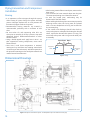
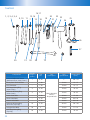
Dimensional Drawings
All dimensions are in mm
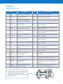
Figure 6. Compressor connection and ports. For identification refer to the Table on the next page.
10
No.
Connection/Port
Size
No.
Connection/Port
Size
1
DPS sensor
3/4”-16UNF
2
Plug low-pressure connection
1/4”-18NPTF
3
Bolt-mounting
M10
4
Plug oil drain
1/4”-18NPTF
5
Nut-oil out fitting
M16
6
Connector DLT/VI/VO/optical OLS/PDS
7
Connector EXV
8
Screw grounding
M5
9
Connector optional
10
Nut- oil in fitting
M16
11
Liquid out
12
Liquid in
3/4”
13
DLT sensor
14
Vapor out temperature sensor
15
Nut- EVI fitting
16
EXV Coil
17
Vapor in temperature sensor
18
Optical oil level sensor
19
Built-in oil screen
20
Oil level sight glass
21
Crankcase heater
22
Low pressure port
23
Suction valve
28.7 ID
24
Plug high-pressure connection
25
Discharge valve
25.7 ID
26
High pressure port
3/4”
M20
M20
7/8”-14UNF
1/4”-18NPTF
Notes: SL: Suction Line
DL: Discharge Line
To disconnect:
• Reclaim refrigerant from both the high and low side of the system. Cut tubing near compressor.
To reconnect:
• Recommended brazing material is one with minimum 45% silver or silver braze material with flux. Insert tubing
stubs into fitting and connect to the system with tubing connectors. Follow instructions on Brazing (3.2.1).
Piping Connections
Copeland Scroll™ Fusion has very low vibration
characteristics, so discharge and suction vibration
eliminators should not be necessary in the majority of
installations. The suction, discharge and liquid pipes
should all have sections running close to the compressor
body in parallel with the shaft to absorb any startup or
shutdown torsion. Vibration is much lower than those
found in equivalent piston compressors, and discharge
pulsations are negligible due to the muffling effect of the
discharge cover.
Min. Distance
500 mm
Min. R
57 mm
Min.
200 mm
Figure 7. Piping guideline
Recommended minimum straight length from discharge
valve to first bending point is 200 mm, minimum bending
radius is 60 mm.
For ease of service, a minimum space of 500 mm between
top cap surface to casing wall is recommended. Refer to
Figure 7.
Vapor Injection and Liquid Line
Temperatures
Copeland Scroll Fusion compressor package applies
vapor injection technology to improve LT operational
efficiency and provides a reliable LT envelope. Vapor
injection subcools the main liquid line and compressor oil
using the integrated plate heat exchanger economizer. The
subcooling of liquid line calls for these recommendations:
1. Liquid line pipe connecting the economizer to the
evaporator expansion valve has to be well insulated
separately. See Liquid Line Insulation for insulation
thickness.
2. The lower liquid line temperature can increase the
evaporator expansion valve capacities. Please follow
valve manufacturers recommended liquid temperature
correction factors for proper selection of evaporator
expansion valve. Refer to catalogue or contact your
local Emerson sales office for liquid line temperatures.
11
Liquid Solenoid Valve
A liquid line solenoid valve is effective in keeping liquid
out of the low side when the system cycles on the
thermostat. The solenoid should be installed close to
the expansion valve to keep the main volume of the
liquid line on the high side of the system during off
periods. All solenoid valves leak slightly and may not
be 100% effective in keeping liquid in the high side
during extended shutdown periods which can occur in
cold rooms used for storing seasonal products. In most
cases, opening and closing the solenoid valve when
the compressor starts and stops provides adequate
protection from liquid migration to the compressor
crankcase.
Liquid Line Insulation
Copeland Scroll™ Fusion compressors have many
characteristics found on two-stage piston compressors,
among them, a cold liquid line after the heat exchanger.
The cold liquid is very important for improving the system
capacity and efficiency, and any increase in liquid line
temperature after the heat exchanger is a system loss.
The liquid line should therefore be insulated with
tightly-fitted closed cell foam. The wall thickness of
the insulation should be at least 10 mm for medium
temperature applications and >15 mm for low
temperature applications. In some low temperature
applications, an uninsulated liquid line could even cause
ice formation, and in humid environments condensation
will occur. The line connecting the receiver to the inlet of
the heat exchanger does not require insulation.
Pumpdown Cycle
Pumpdown cycles are widely applied in systems with
reciprocating compressors. Copeland Scroll Fusion
compressors have inherently superior liquid handling
capability, so a pumpdown at each thermostat cycle is
not recommended. A pumpdown cycle before defrost
will be helpful in reducing the defrost time. Copeland
Scroll Fusion compressors are fitted with a spring loaded
low-leak check valve under the discharge service valve, so
an external check valve should not be necessary. When
pumpdown finishes, the compressor will stop and contain
a very large volume of high pressure gas in the top cap
area. This refrigerant will quickly leak back to suction and
will cause a significant pressure rise that could reset the
low pressure switch. The control circuit should not allow
the compressor to restart; restart should only occur
when the thermostat closes.
12
High Pressure and Low Pressure Cut-out
Settings
A high-pressure control with a maximum cut-out setting
of 28 bar(g) is required. The high-pressure cut-out should
have a manual reset feature for the highest level of system
protection.
The low-pressure cut-out should be set as high as
possible in all applications. For medium temperature
applications the normal minimum is 2.5 bar(g) which
corresponds to -10oC with R22 and -16˚C with R404A.
For low temperature applications the minimum cutout setting should not be lower than 0.3 bar(g) for a
compressor using R404A, and should not be lower than
0.1 bar(g) for a compressor using R22. The cut-out point
of the LP switch must be set using an accurate suction
pressure gauge rather than the scale on the switch which
is provided for rough setting only.
Warning
Copeland Scroll Fusion compressor should NEVER be
allowed to run in a vacuum.
The low-pressure cut-out should have a manual reset
feature for the highest level of system protection.
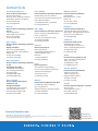
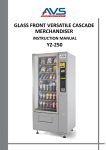
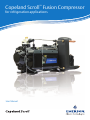
Condenser
Receiver
Discharge
VI
Oil
Filter Drier
(min 100 mesh)
Economizer
(Plate Heat
Exchanger)
Economizer Liquid
Out Line must be
insulated
X
Suction
Sight Glass
Oil Line VI EXV
Solenoid Valve
X
Evaporator
TXV
VI: Vapor Injection
EXV: Electronic Expansion Valve
TXV: Thermostatic Expansion Valve
Fusion Standard BOM
Figure 8. Schematic Diagram
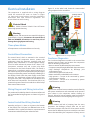
Electrical Installation
Figure 12, on the other hand, shows the recommended
wiring sequence for the control box.
The compressor is supplied with a wiring diagram
inside the terminal box cover as shown in Figure
10. Fuses and circuit breakers must be installed in
accordance with local electrical regulations. The
terminal box has an IP54 rating.
4-Bit Dip Switch
4
42 & 3 ON
ON
DIP
1 2 3 4
Electrical Shock
Conductor Cables! Electrical Shock! Shut Off Power
before High potential testing
Fusse
Fuse
1A
Warning
2A
The compressor and accessories are tested for leakage to
ground before shipping. Disconnect the control board
PWR and DEMAND connections to avoid any risk of
damage during high potential testing.
Three-phase Motors
All compressors can be started direct on line only.
Control Board Connection
The control board, which is mounted in the terminal
box, monitors the compressor sensors, protects the
compressor, drives the electronic expansion valve and
displays useful information in a seven segment display.
Three red LEDs indicate the status of the “Alarm” CCC
(compressor contactor coil) and a spare relay which
is connected to the black terminal block. The board is
powered via a transformer with a nominal output of 16
VAC. When correctly wired and powered up the board goes
through a self checking routine and displays a flashing 0. If
the display is blank check the power supply on the PWR
terminals, the transformer output and the green fuse.
The green fuse (250 V 2A) protects the transformer and
other electronic components. The white fuse (250 V 1A)
protects the system control circuit and the on-board relays
from external short circuits.
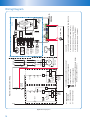
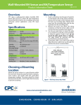
Wiring Diagram and Wiring Instruction
The position of the 4-Bit Dip Switch in the terminal box and
the recommended wiring diagrams are shown in Figures 9
and 10.
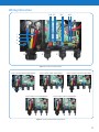
Fusion Control Box Wiring Standard
According to Figure 11, there are 4 joints at the bottom
of the control box. Each joint has dedicated wires to be
assembled. Table 1 explains the function, requirement and
connection method of each joint and wires inside.
Figure 9. CoreSense™ Diagnostics Board
CoreSense Diagnostics
The CoreSense Diagnostics module in the terminal box
monitors several sensors and protects the compressor
from the following malfunctions:
• Reverse rotation by differential oil pressure sensor
• Compressor not pumping by differential oil pressure sensor
• High discharge temperature by discharge port
temperature sensor
• Low oil level by optical oil level sensor
• Motor overheat by embedded four thermistors
• High pressure – cut-out to be connected by system
manufacturer or installer
• Low pressure – cut-out to be connected by system
manufacturer or installer
Warning
High Pressure and Low Pressure switches must be fitted by
the system manufacturer and connected to the pressure
ports shown in the compressor outline drawing on
Figure 6. HP and LP cut-out switches must be electrically
connected as shown in the wiring diagram on Figure 10.
Warning
Reverse rotation and lack of pumping have the same
symptoms: the discharge pressure does not rise and
the suction pressure does not fall. If the control module
senses that the differential pressure switch has not closed
after a short time delay, the compressor will stop, an error
13
14
C
Figure 10. Wiring Diagram
3
4
Q1 - CIRCUIT BREAKER
KT - TIME DELAT RELAY
VAPOR OUT TEMP.SENSOR
VAPOR IN TEMP.SENSOR
DISCHARGE PORT TEMP.SENSOR
Demand-COMPRESSOR ON/OFF FEEDBACK SIGNAL
(PARALLEL CONNECT WITH K1)
2
CCC-COMPRESSOR CONTACTOR COIL RELAY
COMPRESSOR
MOTOR
L
ALARM LIGHT
C D
'HPDQG
N
3:5
TR-PRI
220/240VAC,
50/60Hz
L
2
C
SE0VA
FUA/25
5. CHECK WIRING OF "Alarm" TERMINAL
4. CHECK WIRING OF "Demand" TERMINAL
3. CHECK WIRING OF "Compressor" TERMINAL
2. CHECK WIRING OF "PWR" TERMINAL (N,L)
1. CHECK WIRING OF COMPRESSOR MOTOR POWER SUPPLY
CHECK LIST
MOTOR POWER
TERMINAL
T3
FUSE
OPTION2:
NO PUMP
DOWN
D
E
M1
T2
A B
&&&
1A/250VAC
OPTION1:
PUMP
DOWN
D
'HPDQG
C
T1
$ODUP
PDS
K1
B
T1 T2 T3
9 10 11
'HPDQG
B
&&&
EXV
TR-SEC
PRI
K1
LL
SOLENOID
VALVE
&&&
A
KT
A
ELECTRONIC
EXPANSION
VALVE
8
LP
OLS
KT
7
RED
VOT
K1
6
BLACK
CIRCUIT
BOARD
TRANSFORMER
SEC
LL
SOLENOID
VALVE
T-STAT
5
PRESSURE
DIFFERENTIAL
SWITCH
4
GREEN
VIT
4
3
3
OPTICAL OIL
LEVEL SENSOR
MOTOR
SENSOR
TERMINAL
2
HP
T-STAT
Q1
1
LP
HP
ON/OFF
SWITCH
2
DPT
S1
F
L1 L2 L3
Standard Ex-factory
Wiring
INPUT:220V/240VAC
OUTPUT:16VAC
K1 - COMPRESSOR
CONTACTOR
N
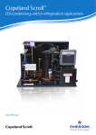
Recommended System Wiring
Wiring Diagram
Wiring Instruction
HG F E
DC
A B
I
J
K
L
4
3
2
1
Figure 11. CoreSense™ Wiring and Joints
Step 1: Connect Compressor Motor Wires
Step 2: Connect “PWR” Terminal Wires
Step 4: Connect “CCC” Terminal Wires
Step 3: Connect “Demand” Terminal Wires
Step 5: Connect “Alarm” Terminal Wires
Figure 12. CoreSense Recommended Wiring Sequence
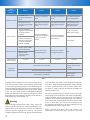
15
Gland
(Waterproof)
Number
Gland 1
Gland 2
Gland 3
Gland 4
For “PWR” and
“Demand” Connector’s
Wires
For “CCC” Connector’s
Wires
For “Alarm” Connector’s
Wires
For Compressor Motor
Power Supply Wires
One jacket line with
four wires goes through
the joint
One jacket line with two
wires goes through the
joint
One jacket line with two
wires goes through the
joint
One jacket (PVC) line
with four wires goes
through the joint
Gland Description
A(Red) and B(Blue):
Controller Power Supply
Input(220-240VAC
50/60Hz)
Wire Function
C(Black) and D(Yellow):
Compressor Start/Stop
Feedback Input(220240VAC 50/60Hz)
I, J, K: Compressor
Motor Power Supply
E(Brown) and F(Blue):
Compressor Diagnostic/
Protection Contact
Output
G(Brown) and H(Blue):
Dry Contact Output For
Alarm Devices
L: Earth Wire
Wires A and B: “PWR”
(Green) connectors
Wire Connection
Gland Internal
Diameter Range
Wires C and D:
“Demand” (Blue)
connectors
5-10 mm
Wires E and F: “CCC”
(Green) connectors
Wires E and F: “Alarm”
(Orange) connectors
5-10 mm
5-10 mm
Internal wire size: 18-20 AWG
Jacket Line
Requirement
N/A
18-25mm
Internal wire seize: 8
AWG or above (4 wires
in total)
Recommended wire size: 18 AWG
Rated voltage: 300V/500V
Rated voltage:
600V/1000V
Table 1
message will be displayed on the control board, and a
timer will be started. Three more attempts will be made
to start and if differential pressure is not established, the
compressor will be locked out. The alarm contact will close
and can be used by the installer to turn on a light, sound
a bell, etc. The alarm contact is voltage-free allowing
maximum flexibility with regard to the type of alarm
device that can be connected. The alarm relay contact is
rated at 250 VAC 1A and 30 VDC 1A.
Warning
High discharge temperatures often occur when the
system is short of refrigerant: suction temperature rises,
bubbles form in the liquid line and there is insufficient
liquid to feed the injection EXV properly. The control
module will stop the compressor, display a fault code and
16
close the alarm relay. After a time delay, the compressor
will restart. High discharge temperature alarms indicate
a serious system problem, and corrective action must
be taken to avoid long term compressor damage and
possible product loss.
Oil level is monitored by an optical sensor in the high
side oil sump. If the level falls to the minimum allowable,
a timer will start and the compressor will be stopped if
sufficient oil has not returned to the sump in one minute.
Two restarts will be attempted after short delays, and
if the oil level does not recover, the compressor will
be stopped and locked out. An alarm message will be
displayed and the alarm relay will close.
Motor overheat may occur when the suction gas
temperature is abnormally high, mass flow is low and
discharge pressure is also high. Four thermistors are
embedded in the windings and monitored by the control
module. If the module senses that the winding temperature
is high, it will stop the compressor and start a timer. A
restart will be attempted when the windings have cooled
and the timer has timed out. The compressor will not be
locked out, but the cause of overheat must be investigated
to prevent long term compressor damage. Motor overheat
can be caused by a mechanical problem, which, if not
rectified quickly, could cause complete compressor failure
and system contamination. Common mechanical problems
that lead to motor trips include worn bearings or worn scroll
sets as a result of overheating.
is coated by system contaminants. The lens will need to
be removed and cleaned to restore correct operation.
The differential pressure switch is normally open when
the compressor is off and pressure has equalised. It can
be checked for continuity using an ohmmeter. When the
compressor starts the resistance should change from
infinity to 0 Ohms. The reed switch, which is enclosed
in plastic, can also be closed by holding it close to a
magnet.
Crankcase Heaters
Differential Oil
Pressure Sensor
Checking Thermistors and Sensors
Table
2 provides resistance values of the thermistors
and Sensors
Discharge Port
Temp. Sensor
Vapor Out
Temp. Sensor
at
several useful temperatures.
Table 2 provides resistance values of the thermistors at
several useful temperatures.
Caution
Use a voltage no higher than 3 VDC when testing.
Caution
An
bath can
be used
at 0
C andwhen
boiling
water can be
Useice
a voltage
no higher
than
3oVDC
testing.
o
used at 100 C.
An ice bath can be used at 0oC and boiling water can be
used at 100oC.
Location
Location
Discharge
Discharge
Vapor In
Vapor In
Vapor Out
Vapor Out
0oC
0oC
326 K Ohm
326 K Ohm
28 K Ohm
28 K Ohm
28 K Ohm
28 K Ohm
Temperature
Temperature
25oC
25oC
100 K Ohm
100 K Ohm
10 K Ohm
10 K Ohm
10 K Ohm
10 K Ohm
Table 2
Table 2
Optical Oil Level Sensor
Vapor In Temp.
Sensor
Figure 14. Sensor Location
100oC
100oC
7 K Ohm
7 K Ohm
950 Ohm
950 Ohm
950 Ohm
950 Ohm
For the motor thermistor chain, the trip resistance is >
For
motor
thermistor
the trip
is >
4.5 the
K Ohms
and
the reset chain,
resistance
is < resistance
2.75 K Ohms.
4.5 K Ohms and the reset resistance is < 2.75 K Ohms.
Resistance at room temperature should be < 500 Ohms.
Resistance at room temperature should be < 500 Ohms.
If the oil level switch is not functioning correctly, the
If the oil level switch is not functioning correctly, the
optical part can be easily changed without breaking into
optical part can be easily changed without breaking
the system. Malfunction is also possible if the lens
into the system. Malfunction is also possible if the lens
Crankcase heaters are very effective in keeping liquid
out of the compressor and are recommended for
all installations. The heater should be on when the
compressor is stopped.
Caution
At the time of initial startup, or after any extended period without power, the heater should be energized 12
hours before starting the compressor. Long off periods
are common in cold stores holding seasonal products, so
it is particularly important to turn on power to the unit
12 hours before restarting after a long idle period. A 220
V 60 W heater is supplied as standard equipment.
Startup and Operation
M25, 5 Sensors
Leak / Pressure Testing
M20, EXV Wires
M20, Motor Power
3xM16, Reserved for customer
The compressor has been pressure tested in the factory.
It is not necessary for the system manufacturer or
installer to pressure test or leak-test the compressor
again although the compressor will normally be exposed
to the pressure used as part of system testing. Consider
personal safety requirements and refer to nameplate test
pressures prior to testing.
Remove Terminal Box Cover
for Customer Wiring
Figure 13. Terminal Box Location For Wiring
17
Warning
Warning
The maximum pressure for leak testing should be no
higher than 22.5 bar(g).
Do not start the compressor while the system is in
a vacuum.
Use only dry nitrogen or dry air for system pressure
testing. DO NOT USE other industrial gases.
Refrigerant Charging
If using dry air do not include the compressor in the
pressure test – isolate it first. Never add refrigerant to the
test gas (as leak indicator).
System Evacuation and Dehydration
Before the installation is put into operation, remove the
holding charge then evacuate with a vacuum pump.
Proper evacuation reduces residual moisture to 50 ppm.
The installation of adequately sized access valves at the
furthest point from the compressor in the suction and
liquid lines is advisable. To achieve undisturbed operation,
the compressor valves are closed and the system is
evacuated down to 0.3 mbar / 0.225 Torr. Pressure must
be measured using a vacuum pressure (Torr) gauge on the
access valves and not on the vacuum pump; this serves to
avoid incorrect measurements resulting from the pressure
gradient along the connecting lines to the pump. Then the
compressor must be evacuated. Due to the factory holding
charge of dry air, the compressor is under pressure (about
1-2.5 bar), this is to indicate the compressor does not leak.
Preliminary Check
Discuss installation details with the installer. If possible,
obtain drawings, wiring diagrams, etc. It is ideal to use a
checklist but always check the following:
• Visual check of the electrics, wiring, fuses etc.
• Visual check of the plant for leaks, loose fittings such
as TXV bulbs etc.
• Compressor oil level
• Calibration of HP and LP switches and any pressure
actuated valves
• Check setting and operation of all safety features and
protection devices
• All valves in the correct running position
• Pressure and compound gauges fitted
• Correctly charged with refrigerant
• Compressor electrical isolator location & position
Warning
Never install a system in the field and leave it unattended
when it has no charge, a holding charge, or with the service
valves closed without securely electrically locking out the
system. This will prevent unauthorized personnel from
accidentally operating the system and potentially ruining
the compressor by operating with no refrigerant flow.
18
PC Board should be powered to close EXV before
charging. The system should be liquid-charged through
the liquid-receiver shut-off valve or through a valve in the
liquid line. The use of a filter drier in the charging line is
highly recommended. Because scrolls have discharge
check valves, systems should be liquid-charged on both
the high and low sides simultaneously to ensure that a
positive refrigerant pressure is present in the compressor
before it runs.
Charging quantity can be determined by referring to system
discharge and suction pressures. Another very useful
parameter is the liquid line temperature which has been
listed in the Fusion Catalogue. At a measured condensing
temperature and an evaporating temperature, the liquid line
temperature should be around Emerson‘s recommendation
value within +5K tolerance.
Warning
The majority of the charge should be placed in the high side
of the system to prevent bearing washout during first-time
start on the assembly line or on site.
Do not operate with a restricted suction. Do not operate
with the low-pressure cut-out bridged. Do not operate
compressor without enough system charge to maintain at
least 0.3 bar suction pressure. Allowing pressure to drop
below 0.3 bar for more than a few seconds may overheat
scrolls and cause early drive bearing damage. If the suction
pressure is low on startup, and top up of the refrigerant
charge is required, it is preferable to bleed liquid slowly
into the suction line of a running compressor than to risk
overheating by vapour charging.
The system should be liquid-charged through the liquidreceiver shut-off valve or through a valve in the liquid
line. The use of a filter drier in the charging line is highly
recommended. The majority of the charge should be
placed in the high side of the system to prevent bearing
washout during first-time start on the assembly line.
Initial Startup
Warning
It is important to ensure that new compressors are not
subjected to liquid abuse. Turn the crankcase heater on 12
hours before starting the compressor..
Maintenance
Refrigerant Exchange
Qualified refrigerants and oils were indicated on page 8. It
is not necessary to replace the refrigerant with a new one
unless contamination due to an error such as topping up
the system with an incorrect refrigerant is suspected. To
verify correct refrigerant composition, a sample can be
taken for chemical analysis. A check can be made during
shut down by comparing the refrigerant temperature and
pressure using precision measurements at a location in
the system where liquid and vapor phases are present and
when the temperatures have been stable.
In the event that the refrigerant needs replacing, the charge
should be recovered using a suitable recovery machine.
When R22 in a system with mineral oil is to be replaced
with R407C or R404A, the oil must also be changed.
Please refer to Technical Information “Refrigerant
changeover from HCFC to HFC Refrigerants”.
Replacing Compressor
Warning
Rotalock valves should be re-torqued periodically to
ensure that leak tightness is maintained. All gaskets and
fittings should be inspected for signs of leaks and repaired
if necessary. Electrical connections should be checked for
tightness. All wires should be clamped securely and routed
away from hot surfaces to prevent damage from vibration
and heat.
Some minor repairs like sensor replacement can be done while
the compressor is still under pressure. To replace components
that are under pressure, shut down the compressor, wait 15
seconds, and turn off all power. Close the service valves, recover
the refrigerant and change the faulty component. Evacuate the
compressor only, open the service valves, and recharge the same
quantity of refrigerant that was recovered.
Warning
Change the accumulator after replacing a compressor with
a burned out motor. The accumulator oil return orifice or
screen may be plugged with debris or may become plugged.
This will result in starvation of oil to the new compressor and
a second failure.
In the case of a motor burnout, the majority of contaminated
oil will be removed with the compressor. The rest of the oil
is cleaned through the use of suction and liquid line filter
driers. A 100% activated alumina suction line filter drier is
recommended but must be removed after 72 hours. It is highly
recommended that the suction accumulator be replaced if the
system contains one. This is because the accumulator oil-return
orifice or screen may be plugged with debris or may become
plugged shortly after a compressor failure. This will result in
starvation of oil to the replacement compressor and a second
failure. When a single compressor or tandem is exchanged in
the field, it is possible that a major portion of the oil may still
be in the system. While this may not affect the reliability of the
replacement compressor, the extra oil will add to rotor drag
and increase power usage.
Lubrication and Oil Removal
Do not mix up ester oils with mineral oil and/or alkyl
benzene when used with chlorine-free (HFC) refrigerants.
The compressor is supplied with an initial oil charge.
The standard oil charge for use with refrigerants R404A
/ R407A / R407C / R407F / R134a is a polyolester (POE)
lubricant Emkarate RL 32 3MAF. In the field, the oil level
could be topped up with Mobil EAL Arctic 22 CC if 3MAF
is not available. The standard mineral oil for R22 is Suniso
3GS. Therefore it is recommended that a properly sized
filter drier is installed in all POE systems. This will maintain
the moisture level in the oil to less than 50 ppm.
Warning
If the moisture content of the oil in a refrigeration system
reaches unacceptably high levels, corrosion and copper
plating may occur. The system should be evacuated down to
0.3 mbar or lower. If there is uncertainty as to the moisture
content in the system, an oil sample should be taken
and tested for moisture. Sight glass/moisture indicators
currently available can be used with the HFC refrigerants
and lubricants; however, the moisture indicator will just
show the moisture content of the refrigerant. The actual
moisture level of POE would be higher than what the sight
glass indicates.
Oil Additives
Although Emerson Climate Technologies cannot
comment on any specific product, from our own testing
and past experience, we do not recommend the use of
any additives to reduce compressor bearing losses or for
any other purpose. Furthermore, the long term chemical
stability of any additive in the presence of refrigerant, low
and high temperatures, and materials commonly found in
refrigeration systems is complex and difficult to evaluate
without rigorously controlled chemical laboratory testing.
19
The use of additives without adequate testing may result
in malfunction or premature failure of components in the
system and, in specific cases, in voiding the warranty on
the component.
Unbrazing System Components
Warning
Oil-refrigerant mixtures are highly flammable. Remove all
refrigerant before opening the system. Avoid working with
an unshielded flame in a refrigerant charged system. Before
opening up a system, it is important to remove all refrigerant
from both the high and low sides of the system. If the
refrigerant charge is removed from a scroll-equipped unit
from the high side only, it is possible for the scrolls to seal,
preventing pressure equalization through the compressor.
This may leave the low side shell and suction line tubing
pressurized. If a brazing torch is applied to the low side while
20
the low side shell and suction line contain pressure, the
pressurized refrigerant and oil mixture could ignite when
it escapes and comes in contact with the brazing flame. To
prevent this occurrence, it is important to check both the
high and low sides with manifold gauges before unbrazing.
Instructions should be provided in appropriate product
literature and assembly (line repair) areas. If compressor
removal is required, the compressor should be cut out of
system instead of unbrazing.
Dismantling and Disposal
Removing oil and refrigerant
• Do not disperse in the environment.
• Use the correct equipment and method of removal.
• Dispose of oil and refrigerant properly.
• Dispose of compressor properly.
Appendix
Fault Diagnostic Code
Code
Description
Status
Compressor Action
0
ON
Normal compressor operation
Normal
Normal compressor operation
0
FLASH
Normal compressor off
Normal
Normal compressor standby
0
FLASH
If it flashes during operation,
follow Emerson Wiring Diagram
Fault
EXV will not work so compressor must stop
1
FLASH
Motor overheat
Fault
Compressor shutdown and automatic reset
after 10 min delay
2
FLASH
High discharge temperature
Fault
Compressor shutdown and automatic reset
after 10 min delay
3
FLASH
Low oil level
Fault
Compressor shutdown and automatic reset
after 5 min delay
4
FLASH
Low differential oil pressure
(HP - LP)
Fault
Compressor shutdown and automatic reset
after 3 min delay
5
FLASH
Motor Thermistor failure
Fault
Compressor shutdown and automatic reset
after 3 min delay
6
FLASH
Scroll temperature sensor failure Fault
Compressor shutdown and automatic reset
after 3 min delay
7
FLASH
PHE inlet temperature sensor
failure
Fault
Compressor shutdown and automatic reset
after 3 min delay
8
FLASH
PHE outet temperature sensor
failure
Fault
Compressor shutdown and automatic reset
after 3 min delay
3 and F
Alternate
display
Less oil level, still OK but
soon dangerous
Normal
Show alarming and continue running. Give
precaution
1 to 8
Number
FLASH
All sensors
Fault
When power on 1st time, if any sensor (except
ols, dps) is wrong, immediately locked
3
Number
FLASH/'.' on
Low oil level/Require
manual reset
Fault
The 4th low oil level in 1 hour, compressor
shutdown and locked, manual reset (cut
off power)
4
Number
FLASH/'.' on
Low differential oil pressure/
require manual reset
Fault
The 4th low differential pressure in 1 hour,
compressor shutdown and locked
• Fault diagnostic code is visible through
a transparent window on the cover
• The code and description can be found
inside of the cover
21
Tool List
16,17
1, 2, 3, 4, 5, 6
13,14
9, 10 11
15
7
18
19
20
22 23
21
24
25
26
27
29
31
30
28
8
12
Components
Item No.
on Page 11
(Table)
Tool
No.
Pressure Differential Sensor
(Mechanical Part, Lower Cover)
1
Three-phase Terminal Plate
Tool
Specification
Torque Value
(N.m)
8, 29
1''
100–110
–
1, 28
10 mm
12–15
PTC Thermistor
–
1, 28
10 mm
12–15
Oil Charge Fitting Plug
(Lower Cover)
2
2, 29
18 mm
32–42
Oil Drain Oil Fitting Plug
(Lower Cover)
4
2, 29
18 mm
32–42
Lower Cover Bolts
–
3, 29
16 mm
57–68
Check Valve Bolts
–
2, 29
18 mm
90–100
Suction Valve Bolts
–
2, 29
18 mm
90–100
Oil Drain Oil Fitting Plug
(Oil screen, Top Cap)
19
4, 29
26 mm
130–140
Oil Sight Glass Bolts
20
5
10 mm
7.5–10
Oil Charge Fitting Plug
(Top Cap)
24
2, 29
18 mm
32–42
22
Tool
Description
Metric Hexagon
Socket,
Torque Wrench
Item No.
on Page 11
(Table)
Tool
No.
Oil Level Sensor
18
Discharge Valve (Rotate)
Tool
Specification
Torque Value
(N.m)
–
29 mm
130–140
25
–
50 mm
54–60
Rotalock Nut for Oil Out Tube
5
9
22 mm
25–30
Rotalock Nut for Oil In Tube
10
9
22 mm
25–30
Nuts of Tube-Oil Pulsation
–
9
22 mm
25–30
EVI Rotalock Nut
15
11
24 mm
40–50
Pressure Differential Sensor
(Mechanical Part, Lower Cover)
1
12
1''
100–110
Terminal Box Cover Screws
–
13
H3/6''
1–2
H3/6''
1–2
M3
N/A
3 mm
3.40–5.10
4 mm
5.65–7.75
4 mm
5–6
5 mm
3.40–5.10
10 mm
80–90
Components
Tool
Description
Opening Wrench
Cross Screwdriver
Screw - CoreSense™ Connect
to Terminal Box
–
14
CoreSense Terminal
Connectors
–
30
Transformer Bolts
–
15, 28
Thrust Plate Bolts
–
16, 28
Oil Separator Bolts
–
17, 28
Bolt - Terminal Box Connect
to Body
–
18, 28
Top Cap Bolts
–
19, 29
Top Cap and Lower Cover
–
22
Flat Chisel
–
N/A
Top Cap and Lower Cover
–
23
Rubber Hammer
–
N/A
Top Cap
–
27
Special Bolts
M12
N/A
HVE Holder
–
25, 28
Special Socket,
Torque Wrench
–
12–15
Scroll Set
–
26
Torque Wrench
M10
N/A
Screw-Upper Counterweight
–
24
Opening Wrench
13 mm
12–15
For Torque Wrench
–
20
Connecting Piece
1/2 to 3/8
N/A
For Socket
–
28
–
5–25
For Socket
–
29
–
30–150
For Torque Wrench
–
31
Extension Bars
–
N/A
——
–
21
Offset Socket Screw
Key Set
1.5 to 10 mm
For Teardown
Only
Voltage Tester
Metric Internal
Hexagon Socket,
Torque Wrench
Torque Wrench
23
Contact Lists
Asia Pacific Headquarters
Emerson Climate Technologies
Suite No. 2503-8, 25/F,
Exchange Tower, 33 Wang Chiu Road,
Kowloon Bay, Kowloon, Hong Kong
Tel: (852) 2866 3108
Fax: (852) 2520 6227
Australia
Emerson Climate Technologies Australia
Pty Ltd
356 Chisholm Road
Auburn NSW 2144, Australia
Tel: (612) 9795 2800
Fax: (612) 9738 1699
China - Beijing
Emerson Climate Technologies (Suzhou)
Co. Ltd
Beijing Sales Office
Room 1017 JianWei Building,
66 Nan Lishi Road, XiCheng District,
Beijing, PRC
Tel: (8610) 5763 0488
Fax: (8610) 5763 0499
India - Mumbai
Emerson Climate Technologies (India) Ltd
Delphi B-Wing, 601-602, 6th Floor
Central Avenue, Hiranandani Business Park,
Powai, Mumbai 400076
Tel: (9122) 2500 6630 / 2500 6632
Fax: (9122) 2500 6570
India - PUNE
Emerson Climate Technologies (India) Ltd
Plot No. 23, Rajiv Gandhi Infotech Park,
Phase - II, Hinjewadi,
Pune 411 057, Maharashtra, India
Tel: (9120) 2553 4988
Fax: (9120) 2553 6350
Indonesia
PT Emerson Indonesia
BSD Taman Tekno 8
Jl. Tekno Widya Blok H10 No 2 & 3
Tangerang Selatan 15314
Indonesia
Tel: (6221) 2666244
Fax: (6221) 2666245
China - Guangzhou
Emerson Climate Technologies (Suzhou)
Co. Ltd
Guangzhou Sales Office
508-509 R&F Yinglong Plaza,
No. 76 Huangpu Road West,
Guangzhou, PRC
Tel: (8620) 2886 7668
Fax: (8620) 2886 7622
Japan
Emerson Japan Ltd
Shin-yokohama Tosho Building
No. 3-9-5 Shin-Yokohama, Kohoku-ku
Yokohama 222-0033 Japan
Tel: (8145) 475 6371
Fax: (8145) 475 3565
China - Shanghai
Emerson Climate Technologies
(Suzhou) Co. Ltd
Shanghai Sales Office
1801 Building B, New CaoHeJing
International Business Center,
391Guiping Rd, Shanghai, PRC
Tel: (8621) 3418 3968
Malaysia
Emerson Electric (Malaysia) Sdn. Bhd.
Level M2, Blk A, Menara PKNS-PJ
Jalan Yong Shook Lin
46050 Petaling Jaya, Selangor, Malaysia
Tel: (603) 7949 9222
Fax: (603) 7949 9333
Middle East & Africa
Emerson Climate Technologies
PO Box 26382
Jebel Ali Free Zone – South
Dubai, UAE
Tel: (9714) 811 8100
Fax: (9714) 886 5465
Philippines
Emerson Climate Technologies
10/F SM Cyber West Avenue, EDSA cor.
West Avenue, Barangay Bungad, Diliman,
Quezon City 1105 Philippines
Tel: (632) 689 7200
South Korea
Emerson Electric Korea Ltd.
3F POBA Gangnam Tower
343, Hakdong-ro, Gangnam-gu,
Seoul 135-820, Republic of Korea
Tel: (822) 3483 1500
Fax: (822) 592 7883
Taiwan
Emerson Electric (Taiwan) Co. Ltd
3F No. 2 DunHua South Road Sec.1,
Taipei (105), Taiwan
Tel: (8862) 8161 7688
Fax: (8862) 81617614
Thailand - Bangkok
Emerson Electric (Thailand) Ltd
34th Floor, TCIF Tower,
1858/133, Bangna Trad,
Bangkok 10260, Thailand
Tel: (662) 716 4700
Fax: (662) 751 4241
Vietnam
Emerson Climate Technologies - Vietnam
Suite 307-308,
123 Truong Dinh St., Dist.3
Ho Chi Minh, Vietnam
Tel: (84) 908 009 189
EmersonClimateAsia.com
Asia 02 B04 10 – R00 Issued 03/2015 – GSCAA032
Emerson, CoreSense Diagnostics and Copeland Scroll Fusion are trademarks of Emerson Electric Co. or one of its affiliated companies.
©2013 Emerson Climate Technologies, Inc. All rights reserved.
Scan With Your
Smartphone For
More Information