1
1.2 Overview
The CC-Link master block FX2N-16CCL-M is a special extension block which assigns an FX Series PLC
as the master station of the CC-Link system.
This manual contains text, diagrams and explanations which will guide the reader in the correct installation
and operation of the FX 2N -16CCL-M CC-Link SYSTEM MASTER BLOCK. It should be read and
understood before attempting to install or use the unit. Further information can be found in the FX series
PLC hardware manuals.
Owing to the very great variety in possible application of this equipment, you must satisfy
yourself as to its suitability for your specific application.
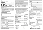
Remote device station
Remote device station
FX0N/FX1N/FX2N/FX2NC CC-Link interface block
Series PLC
FX2N-32CCL
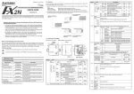
1.3 Dimensions and Setting
MASS (Weight): 0.4 kg (0.88 lbs)
87(3.43)
7)
2
3
4
5
6
7
8
SW
M/S
PRM
TIME
LINE
E
R
R
O
R
901
0 1
9
0 1
9
01
EF 2
0 1
9
ON
1
MITSUBISHI
7 8
80(3.15)
90(3.5)
11)
5 6
SW OFF ON
1
2
3
4 CLR HLD
5
6
7
8
-
2 3
4
0 156K
1 625K
2 2.5M
5M
3
10M
4
89A
MODE
B RATE
4)
5)
6)
3)
7)
SD
RD
1 2 3 4 5 6 7 8
9(0.35)
Inside of top cover
1. INTRODUCTION
1.1 Associated Manuals
Manual name
Manual number
Description
JY992D93101
(sent separately)
Describes programming and handling of the CCLink master block FX2N-16CCL-M.
★FX 1S/FX1N/FX2N/FX2NC
Programming Manual II
JY992D88101
(sent separately)
Explains the instructions in the FX1S/FX1N/FX2N/
FX2NC Series PLC.
✩FX2N Hardware Manual
Describes the contents related to the hardware
JY992D66301
such as specification, wiring and mounting of the
(packed with product)
FX2N Series PLC.
✩FX2N-32CCL
User’s Manual
JY992D71801
Describes programming and handling of the CC(packed with product) Link interface block FX2N-32CCL.
★: Indispensable manual
✩: Manual required depending on equipment used
L RUN
L ERR
MST
TEST1
TEST2
L RUN
L ERR.
2)
Power indictor POWER
8)
The terminals SLD and FG are connected inside.
9)
Terminal block Connects the power supply to operate the master block.
10)
Extension
cable
Next step
extension
connector
DIN rail
mounting
groove
11)
12)
24-
Describes the contents related to the hardware
JY992D76401
such as specification, wiring and mounting of the
(packed with product)
FX2NC Series PLC.
ERR.
ON : Module is normal.
ON
OFF
OFF: Watchdog time error has occurred.
Indicates the communication status with
the stations set in parameter.
ON
: Communication error has
ON or
OFF
occurred in all stations.
flashing
Flashing : Communication error has
occurred in some stations.
ON
OFF
ON : Set as the master station
Test result indication
OFF except during test
Test result indication
ON : Data link is being executed
ON
OFF
(host station).
ON
: Communication error has
occurred (host station).
ON or
Flashing : The settings of the switches 4)
OFF
flashing
to 7) are changed while the
power is ON.
ON
OFF
ON : 24V DC is supplied from the outside.
24+ FG
✩FX2NC Hardware Manual
RUN
ERR.
MST
TEST 1
TEST 2
LED status
Normal
Error
DB
Describes the contents related to the hardware
JY992D89301
such as specification, wiring and mounting of the
(packed with product)
FX1N Series PLC.
RUN
Description
DA
✩FX1N Hardware Manual
Description
LED
name
SLD DG
★FX 2N-16CCL-M
User’s Manual
Number
Name
1)
LED
indicators 1
4 56
2)
345
67
SD
RD
POWER
5 6
E
R
R
O
R
2 3
1)
L RUN
L ERR.
4
SW
M/S
PRM
TIME
LINE
12)
×1
SLD DG DA DB
FX2N-16CCL-M
2) Indicates that the identified danger could POSSIBLY cause physical and property damage.
8)
5 6
POWER
1) Indicates that the identified danger WILL cause physical and property damage.
2 3
4
STATION
NO.
×10
L RUN
L ERR.
Hardware warnings
RUN
ERR.
MST
TEST1
TEST2
FX2N-16CCL-M
7 8
9)
BCD
RUN
ERR.
MST
TEST1
TEST2
2424+ FG
10)
6)
7 8
85(3.34)
75(2.95)
2-φ4.5
78
Dimensions: mm (inches)
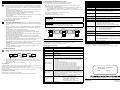
Note’s on the symbology used in this manual
At various times through out this manual certain symbols will be used to highlight points of information
which are intended to ensure the user’s personal safety and protect the integrity of the equipment.
Whenever any of the following symbols are encountered, its associated note must be read and
understood. Each of the symbols used will now be listed with a brief description of its meaning.
Mode setting Sets the operation status of the module. (Default setting at shipment: 0)
switch
Number
Name
Description
0
Online
Sets connection to data link.
1
(Unusable)
MODE
2
Offline
Sets disconnection from data link.
5
4
6
3
3
Line test 1
Refer to USER’S MANUAL.
4
Line test 2
Refer to USER’S MANUAL.
Parameter
5
Refer to USER’S MANUAL.
verification test
6
Hardware test Refer to USER’S MANUAL.
7
(Unusable)
Setting error (The SW LED indicator turns ON.)
8 to A (Unusable)
Cannot be set because it is already used inside.
B to F (Unusable)
Setting error (The SW LED indicator turns ON.)
Transmission Sets the transmission speed of the module. (Default setting at shipment: 0)
speed setting Number
Setting contents
switch
0
156 kbps
B RATE
1
625 kbps
0 156K
2
2.5
Mbps
3
1 625K
2
2 2.5M
3
5 Mbps
3
5M
4 10M
4
10 Mbps
5 to 9 Setting error (The SW and L ERR. LED indicators turn ON.)
Condition
Sets the operation condition. (Default setting at shipment: All OFF)
setting switch Number
Setting description
Switch status
ON
OFF
SW OFF ON ON
1
SW1 to
2
(Unusable)
Always OFF
3
SW3
4 CLR HLD
5
Keep
Clear
6
SW4
Input data status in data link faulty station
7
(HLD)
(CLR)
8
SW5 to
(Unusable)
Always OFF
SW8
Terminal block Connects dedicated CC-Link cables to enable data link. For the connection
method, refer to Section 2.3.
01
EF 2
•
5)
If "65" or larger number is set, the "SW" and "L ERR." LED indicators turn ON.
B CD
All examples and diagrams shown in this manual are intended only as an aid to
understanding the text, not to guarantee operation. Mitsubishi Electric will accept no
responsibility for actual use of the product based on these illustrative examples.
23
×1
78
•
23
× 10
FX1N/FX2N/FX2NC
Series PLC
78 9A
Under no circumstances will Mitsubishi Electric be liable or responsible for any consequential
damage that may arise as a result of the installation or use of this equipment.
Station
number setting
<Setting range>
switch
00 (because the FX2N-16CCL-M is dedicated to the master station)
STATION NO.
4 56
Remote I/O station
If in doubt at any stage during the installation of the FX2N-16CCL-M CC-Link SYSTEM MASTER
BLOCK always consult a professional electrical engineer who is qualified and trained to the local
and national standards. If in doubt about the operation or use of the FX 2N-16CCL-M CC-Link
SYSTEM MASTER BLOCK please consult the nearest Mitsubishi Electric distributor.
•
4)
Remote I/O station
E
R
R
O
R
4 56
Guidelines for the safety of the user and protection of the FX2N-16CCL-M CC-Link
SYSTEM MASTER BLOCK
•
CC-Link master block
FX2N-16CCL-M
Partner manufacturer's
product
Description
ON : Switch setting error has occurred.
OFF
ON
ON : The master station is already
M/S
OFF
ON
present in the same line.
E
OFF
ON
R PRM ON : Parameter setting error has occurred.
R
ON : Data link watchdog timer is actuated
OFF
ON
O TIME
(error in all stations).
R
ON : The cable is broken or the
LINE
transmission route is affected by
OFF
ON
noise, etc.
ON
OFF
SD
ON : Data is being transmitted.
RD
ON : Data is being received.
ON
OFF
Sets the station number of the module. (Default setting at shipment: 00)
SW
SD
RD
2) By using the CC-Link interface block FX2N-32CCL, two or more FX Series PLCs can be connected as
remote device stations to configure a simple distributed system.
901
JY992D93201A
SW
M/S
PRM
TIME
LINE
901
HARDWARE MANUAL
1) Remote I/O stations and remote device stations can be connected to the master station (FX Series
PLC).
Master station
: Station which controls the data link system
Remote I/O station
: Remote station which handles only the 1-bit information
Remote device station : Remote station which handles both bit information and word information
78
FX2N-16CCL-M CC-Link SYSTEM MASTER BLOCK
Number
Name
3)
LED
indicators 2
Connects the PLC.
Connects an extension equipment.
DIN46277: DIN rail mounting groove of 35 mm (1.38") in width
1.2 Overview
The CC-Link master block FX2N-16CCL-M is a special extension block which assigns an FX Series PLC
as the master station of the CC-Link system.
This manual contains text, diagrams and explanations which will guide the reader in the correct installation
and operation of the FX 2N -16CCL-M CC-Link SYSTEM MASTER BLOCK. It should be read and
understood before attempting to install or use the unit. Further information can be found in the FX series
PLC hardware manuals.
Owing to the very great variety in possible application of this equipment, you must satisfy
yourself as to its suitability for your specific application.
Remote device station
Remote device station
FX0N/FX1N/FX2N/FX2NC CC-Link interface block
Series PLC
FX2N-32CCL
1.3 Dimensions and Setting
MASS (Weight): 0.4 kg (0.88 lbs)
87(3.43)
7)
2
3
4
5
6
7
8
SW
M/S
PRM
TIME
LINE
E
R
R
O
R
901
0 1
9
0 1
9
01
EF 2
0 1
9
ON
1
MITSUBISHI
7 8
80(3.15)
90(3.5)
11)
5 6
SW OFF ON
1
2
3
4 CLR HLD
5
6
7
8
-
2 3
4
0 156K
1 625K
2 2.5M
5M
3
10M
4
89A
MODE
B RATE
4)
5)
6)
3)
7)
SD
RD
1 2 3 4 5 6 7 8
9(0.35)
Inside of top cover
1. INTRODUCTION
1.1 Associated Manuals
Manual name
Manual number
Description
JY992D93101
(sent separately)
Describes programming and handling of the CCLink master block FX2N-16CCL-M.
★FX 1S/FX1N/FX2N/FX2NC
Programming Manual II
JY992D88101
(sent separately)
Explains the instructions in the FX1S/FX1N/FX2N/
FX2NC Series PLC.
✩FX2N Hardware Manual
Describes the contents related to the hardware
JY992D66301
such as specification, wiring and mounting of the
(packed with product)
FX2N Series PLC.
✩FX2N-32CCL
User’s Manual
JY992D71801
Describes programming and handling of the CC(packed with product) Link interface block FX2N-32CCL.
★: Indispensable manual
✩: Manual required depending on equipment used
L RUN
L ERR
MST
TEST1
TEST2
L RUN
L ERR.
2)
Power indictor POWER
8)
The terminals SLD and FG are connected inside.
9)
Terminal block Connects the power supply to operate the master block.
10)
Extension
cable
Next step
extension
connector
DIN rail
mounting
groove
11)
12)
24-
Describes the contents related to the hardware
JY992D76401
such as specification, wiring and mounting of the
(packed with product)
FX2NC Series PLC.
ERR.
ON : Module is normal.
ON
OFF
OFF: Watchdog time error has occurred.
Indicates the communication status with
the stations set in parameter.
ON
: Communication error has
ON or
OFF
occurred in all stations.
flashing
Flashing : Communication error has
occurred in some stations.
ON
OFF
ON : Set as the master station
Test result indication
OFF except during test
Test result indication
ON : Data link is being executed
ON
OFF
(host station).
ON
: Communication error has
occurred (host station).
ON or
Flashing : The settings of the switches 4)
OFF
flashing
to 7) are changed while the
power is ON.
ON
OFF
ON : 24V DC is supplied from the outside.
24+ FG
✩FX2NC Hardware Manual
RUN
ERR.
MST
TEST 1
TEST 2
LED status
Normal
Error
DB
Describes the contents related to the hardware
JY992D89301
such as specification, wiring and mounting of the
(packed with product)
FX1N Series PLC.
RUN
Description
DA
✩FX1N Hardware Manual
Description
LED
name
SLD DG
★FX 2N-16CCL-M
User’s Manual
Number
Name
1)
LED
indicators 1
4 56
2)
345
67
SD
RD
POWER
5 6
E
R
R
O
R
2 3
1)
L RUN
L ERR.
4
SW
M/S
PRM
TIME
LINE
12)
×1
SLD DG DA DB
FX2N-16CCL-M
2) Indicates that the identified danger could POSSIBLY cause physical and property damage.
8)
5 6
POWER
1) Indicates that the identified danger WILL cause physical and property damage.
2 3
4
STATION
NO.
×10
L RUN
L ERR.
Hardware warnings
RUN
ERR.
MST
TEST1
TEST2
FX2N-16CCL-M
7 8
9)
BCD
RUN
ERR.
MST
TEST1
TEST2
2424+ FG
10)
6)
7 8
85(3.34)
75(2.95)
2-φ4.5
78
Dimensions: mm (inches)
Note’s on the symbology used in this manual
At various times through out this manual certain symbols will be used to highlight points of information
which are intended to ensure the user’s personal safety and protect the integrity of the equipment.
Whenever any of the following symbols are encountered, its associated note must be read and
understood. Each of the symbols used will now be listed with a brief description of its meaning.
Mode setting Sets the operation status of the module. (Default setting at shipment: 0)
switch
Number
Name
Description
0
Online
Sets connection to data link.
1
(Unusable)
MODE
2
Offline
Sets disconnection from data link.
5
4
6
3
3
Line test 1
Refer to USER’S MANUAL.
4
Line test 2
Refer to USER’S MANUAL.
Parameter
5
Refer to USER’S MANUAL.
verification test
6
Hardware test Refer to USER’S MANUAL.
7
(Unusable)
Setting error (The SW LED indicator turns ON.)
8 to A (Unusable)
Cannot be set because it is already used inside.
B to F (Unusable)
Setting error (The SW LED indicator turns ON.)
Transmission Sets the transmission speed of the module. (Default setting at shipment: 0)
speed setting Number
Setting contents
switch
0
156 kbps
B RATE
1
625 kbps
0 156K
2
2.5
Mbps
3
1 625K
2
2 2.5M
3
5 Mbps
3
5M
4 10M
4
10 Mbps
5 to 9 Setting error (The SW and L ERR. LED indicators turn ON.)
Condition
Sets the operation condition. (Default setting at shipment: All OFF)
setting switch Number
Setting description
Switch status
ON
OFF
SW OFF ON ON
1
SW1 to
2
(Unusable)
Always OFF
3
SW3
4 CLR HLD
5
Keep
Clear
6
SW4
Input data status in data link faulty station
7
(HLD)
(CLR)
8
SW5 to
(Unusable)
Always OFF
SW8
Terminal block Connects dedicated CC-Link cables to enable data link. For the connection
method, refer to Section 2.3.
01
EF 2
•
5)
If "65" or larger number is set, the "SW" and "L ERR." LED indicators turn ON.
B CD
All examples and diagrams shown in this manual are intended only as an aid to
understanding the text, not to guarantee operation. Mitsubishi Electric will accept no
responsibility for actual use of the product based on these illustrative examples.
23
×1
78
•
23
× 10
FX1N/FX2N/FX2NC
Series PLC
78 9A
Under no circumstances will Mitsubishi Electric be liable or responsible for any consequential
damage that may arise as a result of the installation or use of this equipment.
Station
number setting
<Setting range>
switch
00 (because the FX2N-16CCL-M is dedicated to the master station)
STATION NO.
4 56
Remote I/O station
If in doubt at any stage during the installation of the FX2N-16CCL-M CC-Link SYSTEM MASTER
BLOCK always consult a professional electrical engineer who is qualified and trained to the local
and national standards. If in doubt about the operation or use of the FX 2N-16CCL-M CC-Link
SYSTEM MASTER BLOCK please consult the nearest Mitsubishi Electric distributor.
•
4)
Remote I/O station
E
R
R
O
R
4 56
Guidelines for the safety of the user and protection of the FX2N-16CCL-M CC-Link
SYSTEM MASTER BLOCK
•
CC-Link master block
FX2N-16CCL-M
Partner manufacturer's
product
Description
ON : Switch setting error has occurred.
OFF
ON
ON : The master station is already
M/S
OFF
ON
present in the same line.
E
OFF
ON
R PRM ON : Parameter setting error has occurred.
R
ON : Data link watchdog timer is actuated
OFF
ON
O TIME
(error in all stations).
R
ON : The cable is broken or the
LINE
transmission route is affected by
OFF
ON
noise, etc.
ON
OFF
SD
ON : Data is being transmitted.
RD
ON : Data is being received.
ON
OFF
Sets the station number of the module. (Default setting at shipment: 00)
SW
SD
RD
2) By using the CC-Link interface block FX2N-32CCL, two or more FX Series PLCs can be connected as
remote device stations to configure a simple distributed system.
901
JY992D93201A
SW
M/S
PRM
TIME
LINE
901
HARDWARE MANUAL
1) Remote I/O stations and remote device stations can be connected to the master station (FX Series
PLC).
Master station
: Station which controls the data link system
Remote I/O station
: Remote station which handles only the 1-bit information
Remote device station : Remote station which handles both bit information and word information
78
FX2N-16CCL-M CC-Link SYSTEM MASTER BLOCK
Number
Name
3)
LED
indicators 2
Connects the PLC.
Connects an extension equipment.
DIN46277: DIN rail mounting groove of 35 mm (1.38") in width
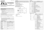
2.3 Module Wiring with Dedicated CC-Link Cables
2. Installation and wiring
INSTALLATION PRECAUTIONS
•
•
•
•
Use the module in the environment described in the USER’S MANUAL General Specification.
Do not use the PLC in a place with dust, soot, conductive dust, corrosive gas or combustible
gas, place exposed to high temperature, condensation, wind or rain or place with vibration or
impact.
Using the module outside the range of the general specification may result in electrical shock,
fire, malfunctions, or may damage the PLC.
When drilling screw holes or performing wiring, make sure that cutting chips, wire chips or
other foreign matter does not enter the ventilation window of the module.
Such matter may cause fire, failure or malfunction.
When the installation work is completed, remove the dust protection sheet from the ventilation
window of the PLC.
If the sheet remains attached, it may cause fire, failure or malfunction.
Securely connect extension cables to specified connectors.
Poor contact may cause malfunction.
•
•
•
•
Before beginning any installation or wiring work, make sure all phases of the power supply
have been shut down from the outside.
Incomplete shutdown of the power supply phases may cause electrical shock or damage in the
module.
Following an installation or wiring work, when turning on the power supply and operating the
PLC, make sure that the terminal cover provided as an accessory has been attached to the
module.
Non-attachment of the cover may cause electrical shock.
For the CC-Link system, use dedicated cables specified by the manufacturer.
The performance of the CC-Link system cannot be guaranteed with any cable other than
dedicated ones specified by the manufacturer.
For the maximum total extension length and the cable length between stations, observe the
specification described in USER’S MANUAL.
With wiring outside the specification range, normal data transfer cannot be guaranteed.
Make sure to fix communication cables and power cables connected to the module by placing
them in the duct or clamping them.
Cables not placed in duct or not clamped may hang or shift, allowing them to be accidentally
pulled, which may result in malfunction or damage to the module and the cables.
When disconnecting a communication/power cable connected to the module, do not hold the
cable area.
For a cable with connector, hold the connector attached to the module.
For a cable connected to a terminal block, loosen screws of the terminal block, then disconnect
the cable.
If a cable is pulled while it is connected to a module, the module may malfunction or the
module and the cable may be damaged.
WIRING PRECAUTIONS
•
Perform Class D grounding (solid grounding) with a wire of 2 mm or more to the grounding
terminal in the PLC main units. However, never perform common grounding with a high voltage
system.
Another
equipment
Dedicated grounding
(best)
•
Make sure to connect a terminal resistor (offered as an accessory of the module) between the
terminals DA and DB in modules at both ends.
•
In the CC-Link system, the terminal resistor to be connected varies depending on the used cable.
Error control method
CRC(X16+X12+X5+1)
Connection cable
Dedicated CC-Link cable/Dedicated high-performance CC-Link cable *1
• Automatic return function
• Slave station cutoff function
• Error detection by link special relay/register
-
When a dedicated CC-Link cable is used: 110 Ω, 1/2 W (brown, brown and brown)
When a dedicated high-performance CC-Link cable is used: 130 Ω, 1/2 W (brown, orange and
brown)
•
The master module can be connected besides to the both ends.
•
Star connection is not allowed.
•
The figure below shows the connection method.
PLC
Another
equipment
Common grounding
(allowed)
PLC
Another
equipment
Common grounding
(not allowed)
Do not bundle control cables and communication cables with the main circuit and power
cables. Keep control cables and communication cables at least 100 mm away from the main
circuit and power cables.
Otherwise, electric noise may cause a malfunction.
2.1 Installation
Install the FX2N-16CCL-M on the right side of an FX1N/FX 2N/FX 2NC Series main unit, extension unit or
another extension block. (For the FX2NC Series, the FX2NC-CNV-IF is required.)
The FX2N-16CCL-M can be installed using a DIN rail (DIN 46277, width: 35 mm (1.38 in.)) or directly with
M4 (0.16 in.) screws.
In the case of direct installation, provide space of 1 to 2 mm (0.04 to 0.08 in.) between units.
2.2 Dedicated CC-Link Cable
Use dedicated CC-Link cables in the CC-Link system.
If any other cable is used, the performance of the CC-Link system cannot be guaranteed.
RAS function
Number of times of
parameter registration
to EEPROM
Specification
Frame synchronous method
NRZI method
Bus (RS-485)
In conformance to HDLC Standard
Approximately 10,000 times
FX1N, FX2N (V 2.20 or later) and FX2NC (V 2.20 or later) *2 Series PLC
Number of occupied
8 I/O points of FX Series PLC (8 points in total. The ratio between inputs and
I/O points
outputs is arbitrary.)
Communication with PLC By FROM/TO instructions via the buffer memory
• Scan method: Asynchronous mode
• Automatic refresh: Not provided
Note
• Local station function: Not provided
• Standby master station function: Not provided
• Intelligent device station connection function: Not provided
POWER : Lit while 24V DC is supplied from outside.
L RUN : Lit while communication is normal.
Operation indication
L ERR : Lit when communication error has occurred.
SD
: Lit while data is being transmitted.
RD
: Lit while data is being received.
24V DC external power
Supplied from 24V DC (150 mA) external terminal block.
supply
5V DC internal power
5V DC is self-supplied. 5V DC of PLC is not used.
supply
Terminal resistor
• For standard cable:
110 Ω, 1/2 W (color cable: brown, brown and brown), 2 cables
Accessories
• For high performance cable:
130 Ω, 1/2 W (color cable: brown, orange and brown), 2 cables
Special block number label
MASS (Weight)
0.4 kg (0.88 lbs)
Connectable PLC
Important
Point
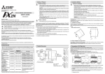
The shielded dedicated CC-Link cable should go through the terminals SLD and FG in each
module, and both ends should be grounded (Class D = solid grounding).
The terminals SLD and FG are connected each other inside the module.
Master module
Remote module
Remote module
DA
DA
DA
DB
DB
DB
Terminal
resistor
DG
SLD
DG
Dedicated CC-Link cable
FG
SLD
Terminal
resistor
DG
Dedicated CC-Link cable
FG
SLD
FG
3. SPECIFICATION
3.1 General Specification
Dielectric strength: 500V AC for 1 minute (between the case and the PLC ground)
Other specification is equivalent to that of the PLC main unit.
3.2 Performance Specification
Item
Applicable function
2
PLC
The cables can be connected without regard to the station number.
•
Make sure to use only one type of cable (dedicated CC-Link cables OR dedicated CC-Link highperformance cables).
If both types of cables are used together, normal data transmission cannot be guaranteed.
WIRING PRECAUTIONS
•
•
Item
Synchronous method
Encoding method
Transmission path type
Transmission format
This section describes the connection method of dedicated CC-Link cables.
CC-Link version
Transmission speed
Station number
Maximum total cable
length (maximum
transmission distance)
*1 Dedicated CC-Link cables and dedicated high-performance CC-Link cables cannot be used at the
same time. Only either type of cables are available.
Attach a terminal resistor in accordance with the cable type.
*2 When an FX2NC Series PLC is connected, the interface FX2NC-CNV-IF is required.
Specification
Master station function (The local station and standby master station functions
are not provided.)
Ver.1.10
Selectable (by rotary switch) among 156 kbps, 625 kbps, 2.5 Mbps, 5 Mbps
and 10 Mbps
0 (set by rotary switch)
1,200 m maximum
Varies depending on the transmission speed. (Refer to USER’S MANUAL.)
•
Remote I/O stations: 7 maximum (Each station occupies 32 I/O points of
the PLC.)
• Remote device stations: 8 maximum (The following condition must be
satisfied.)
{(1×a)+(2×b)+(3×c)+(4×d)} ≤ 8
a: Number of remote device stations occupying 1 station
Maximum number of
b: Number of remote device stations occupying 2 stations
connected modules
c: Number of remote device stations occupying 3 stations
d: Number of remote device stations occupying 4 stations
• Number of remote I/O stations + Number of remote device stations ≤ 15
"Maximum number of I/O points per system" below shall be satisfied.
• For the system configuration calculation, refer to USER’S MANUAL.
• Connection is allowed as far as the following condition is satisfied:
(Actual number of I/O points of PLC) + (Number of points occupied by
special extension blocks) + (Number of points occupied by FX2N-16CCLMaximum number of I/O
M: 8) + (32 × Number of remote I/O modules) ≤ 256 (FX2N/FX2NC Series
points per system
PLC) or 128 (FX1N Series PLC)
• For the system configuration calculation, refer to USER’S MANUAL.
Remote I/O station
: Remote I/O = 32/32 (RX/RY) points
Remote device station : Remote I/O = 32/32 (RX/RY) points
Number of link points
Remote register = 4 (RWw) points
per station
(master station → remote device station)
Remote register = 4 (RWr) points
(remote device station → master station)
Communication method Polling method
Manual number : JY992D93201
Manual revision : A
Date
: JAN. 2001
HEAD OFFICE : MITSUBISHI DENKI BLDG MARUNOUTI TOKYO 100-8310
HIMEJI WORKS : 840, CHIYODA CHO, HIMEJI, JAPAN
JY992D93201A
TELEX : J24532 CABLE MELCO TOKYO
Effective JAN. 2001
Specifications are subject to
change without notice
2.3 Module Wiring with Dedicated CC-Link Cables
2. Installation and wiring
INSTALLATION PRECAUTIONS
•
•
•
•
Use the module in the environment described in the USER’S MANUAL General Specification.
Do not use the PLC in a place with dust, soot, conductive dust, corrosive gas or combustible
gas, place exposed to high temperature, condensation, wind or rain or place with vibration or
impact.
Using the module outside the range of the general specification may result in electrical shock,
fire, malfunctions, or may damage the PLC.
When drilling screw holes or performing wiring, make sure that cutting chips, wire chips or
other foreign matter does not enter the ventilation window of the module.
Such matter may cause fire, failure or malfunction.
When the installation work is completed, remove the dust protection sheet from the ventilation
window of the PLC.
If the sheet remains attached, it may cause fire, failure or malfunction.
Securely connect extension cables to specified connectors.
Poor contact may cause malfunction.
•
•
•
•
Before beginning any installation or wiring work, make sure all phases of the power supply
have been shut down from the outside.
Incomplete shutdown of the power supply phases may cause electrical shock or damage in the
module.
Following an installation or wiring work, when turning on the power supply and operating the
PLC, make sure that the terminal cover provided as an accessory has been attached to the
module.
Non-attachment of the cover may cause electrical shock.
For the CC-Link system, use dedicated cables specified by the manufacturer.
The performance of the CC-Link system cannot be guaranteed with any cable other than
dedicated ones specified by the manufacturer.
For the maximum total extension length and the cable length between stations, observe the
specification described in USER’S MANUAL.
With wiring outside the specification range, normal data transfer cannot be guaranteed.
Make sure to fix communication cables and power cables connected to the module by placing
them in the duct or clamping them.
Cables not placed in duct or not clamped may hang or shift, allowing them to be accidentally
pulled, which may result in malfunction or damage to the module and the cables.
When disconnecting a communication/power cable connected to the module, do not hold the
cable area.
For a cable with connector, hold the connector attached to the module.
For a cable connected to a terminal block, loosen screws of the terminal block, then disconnect
the cable.
If a cable is pulled while it is connected to a module, the module may malfunction or the
module and the cable may be damaged.
WIRING PRECAUTIONS
•
Perform Class D grounding (solid grounding) with a wire of 2 mm or more to the grounding
terminal in the PLC main units. However, never perform common grounding with a high voltage
system.
Another
equipment
Dedicated grounding
(best)
•
Make sure to connect a terminal resistor (offered as an accessory of the module) between the
terminals DA and DB in modules at both ends.
•
In the CC-Link system, the terminal resistor to be connected varies depending on the used cable.
Error control method
CRC(X16+X12+X5+1)
Connection cable
Dedicated CC-Link cable/Dedicated high-performance CC-Link cable *1
• Automatic return function
• Slave station cutoff function
• Error detection by link special relay/register
-
When a dedicated CC-Link cable is used: 110 Ω, 1/2 W (brown, brown and brown)
When a dedicated high-performance CC-Link cable is used: 130 Ω, 1/2 W (brown, orange and
brown)
•
The master module can be connected besides to the both ends.
•
Star connection is not allowed.
•
The figure below shows the connection method.
PLC
Another
equipment
Common grounding
(allowed)
PLC
Another
equipment
Common grounding
(not allowed)
Do not bundle control cables and communication cables with the main circuit and power
cables. Keep control cables and communication cables at least 100 mm away from the main
circuit and power cables.
Otherwise, electric noise may cause a malfunction.
2.1 Installation
Install the FX2N-16CCL-M on the right side of an FX1N/FX 2N/FX 2NC Series main unit, extension unit or
another extension block. (For the FX2NC Series, the FX2NC-CNV-IF is required.)
The FX2N-16CCL-M can be installed using a DIN rail (DIN 46277, width: 35 mm (1.38 in.)) or directly with
M4 (0.16 in.) screws.
In the case of direct installation, provide space of 1 to 2 mm (0.04 to 0.08 in.) between units.
2.2 Dedicated CC-Link Cable
Use dedicated CC-Link cables in the CC-Link system.
If any other cable is used, the performance of the CC-Link system cannot be guaranteed.
RAS function
Number of times of
parameter registration
to EEPROM
Specification
Frame synchronous method
NRZI method
Bus (RS-485)
In conformance to HDLC Standard
Approximately 10,000 times
FX1N, FX2N (V 2.20 or later) and FX2NC (V 2.20 or later) *2 Series PLC
Number of occupied
8 I/O points of FX Series PLC (8 points in total. The ratio between inputs and
I/O points
outputs is arbitrary.)
Communication with PLC By FROM/TO instructions via the buffer memory
• Scan method: Asynchronous mode
• Automatic refresh: Not provided
Note
• Local station function: Not provided
• Standby master station function: Not provided
• Intelligent device station connection function: Not provided
POWER : Lit while 24V DC is supplied from outside.
L RUN : Lit while communication is normal.
Operation indication
L ERR : Lit when communication error has occurred.
SD
: Lit while data is being transmitted.
RD
: Lit while data is being received.
24V DC external power
Supplied from 24V DC (150 mA) external terminal block.
supply
5V DC internal power
5V DC is self-supplied. 5V DC of PLC is not used.
supply
Terminal resistor
• For standard cable:
110 Ω, 1/2 W (color cable: brown, brown and brown), 2 cables
Accessories
• For high performance cable:
130 Ω, 1/2 W (color cable: brown, orange and brown), 2 cables
Special block number label
MASS (Weight)
0.4 kg (0.88 lbs)
Connectable PLC
Important
Point
The shielded dedicated CC-Link cable should go through the terminals SLD and FG in each
module, and both ends should be grounded (Class D = solid grounding).
The terminals SLD and FG are connected each other inside the module.
Master module
Remote module
Remote module
DA
DA
DA
DB
DB
DB
Terminal
resistor
DG
SLD
DG
Dedicated CC-Link cable
FG
SLD
Terminal
resistor
DG
Dedicated CC-Link cable
FG
SLD
FG
3. SPECIFICATION
3.1 General Specification
Dielectric strength: 500V AC for 1 minute (between the case and the PLC ground)
Other specification is equivalent to that of the PLC main unit.
3.2 Performance Specification
Item
Applicable function
2
PLC
The cables can be connected without regard to the station number.
•
Make sure to use only one type of cable (dedicated CC-Link cables OR dedicated CC-Link highperformance cables).
If both types of cables are used together, normal data transmission cannot be guaranteed.
WIRING PRECAUTIONS
•
•
Item
Synchronous method
Encoding method
Transmission path type
Transmission format
This section describes the connection method of dedicated CC-Link cables.
CC-Link version
Transmission speed
Station number
Maximum total cable
length (maximum
transmission distance)
*1 Dedicated CC-Link cables and dedicated high-performance CC-Link cables cannot be used at the
same time. Only either type of cables are available.
Attach a terminal resistor in accordance with the cable type.
*2 When an FX2NC Series PLC is connected, the interface FX2NC-CNV-IF is required.
Specification
Master station function (The local station and standby master station functions
are not provided.)
Ver.1.10
Selectable (by rotary switch) among 156 kbps, 625 kbps, 2.5 Mbps, 5 Mbps
and 10 Mbps
0 (set by rotary switch)
1,200 m maximum
Varies depending on the transmission speed. (Refer to USER’S MANUAL.)
•
Remote I/O stations: 7 maximum (Each station occupies 32 I/O points of
the PLC.)
• Remote device stations: 8 maximum (The following condition must be
satisfied.)
{(1×a)+(2×b)+(3×c)+(4×d)} ≤ 8
a: Number of remote device stations occupying 1 station
Maximum number of
b: Number of remote device stations occupying 2 stations
connected modules
c: Number of remote device stations occupying 3 stations
d: Number of remote device stations occupying 4 stations
• Number of remote I/O stations + Number of remote device stations ≤ 15
"Maximum number of I/O points per system" below shall be satisfied.
• For the system configuration calculation, refer to USER’S MANUAL.
• Connection is allowed as far as the following condition is satisfied:
(Actual number of I/O points of PLC) + (Number of points occupied by
special extension blocks) + (Number of points occupied by FX2N-16CCLMaximum number of I/O
M: 8) + (32 × Number of remote I/O modules) ≤ 256 (FX2N/FX2NC Series
points per system
PLC) or 128 (FX1N Series PLC)
• For the system configuration calculation, refer to USER’S MANUAL.
Remote I/O station
: Remote I/O = 32/32 (RX/RY) points
Remote device station : Remote I/O = 32/32 (RX/RY) points
Number of link points
Remote register = 4 (RWw) points
per station
(master station → remote device station)
Remote register = 4 (RWr) points
(remote device station → master station)
Communication method Polling method
Manual number : JY992D93201
Manual revision : A
Date
: JAN. 2001
HEAD OFFICE : MITSUBISHI DENKI BLDG MARUNOUTI TOKYO 100-8310
HIMEJI WORKS : 840, CHIYODA CHO, HIMEJI, JAPAN
JY992D93201A
TELEX : J24532 CABLE MELCO TOKYO
Effective JAN. 2001
Specifications are subject to
change without notice
1.2 Overview
The CC-Link master block FX2N-16CCL-M is a special extension block which assigns an FX Series PLC
as the master station of the CC-Link system.
This manual contains text, diagrams and explanations which will guide the reader in the correct installation
and operation of the FX 2N -16CCL-M CC-Link SYSTEM MASTER BLOCK. It should be read and
understood before attempting to install or use the unit. Further information can be found in the FX series
PLC hardware manuals.
Owing to the very great variety in possible application of this equipment, you must satisfy
yourself as to its suitability for your specific application.
Remote device station
Remote device station
FX0N/FX1N/FX2N/FX2NC CC-Link interface block
Series PLC
FX2N-32CCL
1.3 Dimensions and Setting
MASS (Weight): 0.4 kg (0.88 lbs)
87(3.43)
7)
2
3
4
5
6
7
8
SW
M/S
PRM
TIME
LINE
E
R
R
O
R
901
0 1
9
0 1
9
01
EF 2
0 1
9
ON
1
MITSUBISHI
7 8
80(3.15)
90(3.5)
11)
5 6
SW OFF ON
1
2
3
4 CLR HLD
5
6
7
8
-
2 3
4
0 156K
1 625K
2 2.5M
5M
3
10M
4
89A
MODE
B RATE
4)
5)
6)
3)
7)
SD
RD
1 2 3 4 5 6 7 8
9(0.35)
Inside of top cover
1. INTRODUCTION
1.1 Associated Manuals
Manual name
Manual number
Description
JY992D93101
(sent separately)
Describes programming and handling of the CCLink master block FX2N-16CCL-M.
★FX 1S/FX1N/FX2N/FX2NC
Programming Manual II
JY992D88101
(sent separately)
Explains the instructions in the FX1S/FX1N/FX2N/
FX2NC Series PLC.
✩FX2N Hardware Manual
Describes the contents related to the hardware
JY992D66301
such as specification, wiring and mounting of the
(packed with product)
FX2N Series PLC.
✩FX2N-32CCL
User’s Manual
JY992D71801
Describes programming and handling of the CC(packed with product) Link interface block FX2N-32CCL.
★: Indispensable manual
✩: Manual required depending on equipment used
L RUN
L ERR
MST
TEST1
TEST2
L RUN
L ERR.
2)
Power indictor POWER
8)
The terminals SLD and FG are connected inside.
9)
Terminal block Connects the power supply to operate the master block.
10)
Extension
cable
Next step
extension
connector
DIN rail
mounting
groove
11)
12)
24-
Describes the contents related to the hardware
JY992D76401
such as specification, wiring and mounting of the
(packed with product)
FX2NC Series PLC.
ERR.
ON : Module is normal.
ON
OFF
OFF: Watchdog time error has occurred.
Indicates the communication status with
the stations set in parameter.
ON
: Communication error has
ON or
OFF
occurred in all stations.
flashing
Flashing : Communication error has
occurred in some stations.
ON
OFF
ON : Set as the master station
Test result indication
OFF except during test
Test result indication
ON : Data link is being executed
ON
OFF
(host station).
ON
: Communication error has
occurred (host station).
ON or
Flashing : The settings of the switches 4)
OFF
flashing
to 7) are changed while the
power is ON.
ON
OFF
ON : 24V DC is supplied from the outside.
24+ FG
✩FX2NC Hardware Manual
RUN
ERR.
MST
TEST 1
TEST 2
LED status
Normal
Error
DB
Describes the contents related to the hardware
JY992D89301
such as specification, wiring and mounting of the
(packed with product)
FX1N Series PLC.
RUN
Description
DA
✩FX1N Hardware Manual
Description
LED
name
SLD DG
★FX 2N-16CCL-M
User’s Manual
Number
Name
1)
LED
indicators 1
4 56
2)
345
67
SD
RD
POWER
5 6
E
R
R
O
R
2 3
1)
L RUN
L ERR.
4
SW
M/S
PRM
TIME
LINE
12)
×1
SLD DG DA DB
FX2N-16CCL-M
2) Indicates that the identified danger could POSSIBLY cause physical and property damage.
8)
5 6
POWER
1) Indicates that the identified danger WILL cause physical and property damage.
2 3
4
STATION
NO.
×10
L RUN
L ERR.
Hardware warnings
RUN
ERR.
MST
TEST1
TEST2
FX2N-16CCL-M
7 8
9)
BCD
RUN
ERR.
MST
TEST1
TEST2
2424+ FG
10)
6)
7 8
85(3.34)
75(2.95)
2-φ4.5
78
Dimensions: mm (inches)
Note’s on the symbology used in this manual
At various times through out this manual certain symbols will be used to highlight points of information
which are intended to ensure the user’s personal safety and protect the integrity of the equipment.
Whenever any of the following symbols are encountered, its associated note must be read and
understood. Each of the symbols used will now be listed with a brief description of its meaning.
Mode setting Sets the operation status of the module. (Default setting at shipment: 0)
switch
Number
Name
Description
0
Online
Sets connection to data link.
1
(Unusable)
MODE
2
Offline
Sets disconnection from data link.
5
4
6
3
3
Line test 1
Refer to USER’S MANUAL.
4
Line test 2
Refer to USER’S MANUAL.
Parameter
5
Refer to USER’S MANUAL.
verification test
6
Hardware test Refer to USER’S MANUAL.
7
(Unusable)
Setting error (The SW LED indicator turns ON.)
8 to A (Unusable)
Cannot be set because it is already used inside.
B to F (Unusable)
Setting error (The SW LED indicator turns ON.)
Transmission Sets the transmission speed of the module. (Default setting at shipment: 0)
speed setting Number
Setting contents
switch
0
156 kbps
B RATE
1
625 kbps
0 156K
2
2.5
Mbps
3
1 625K
2
2 2.5M
3
5 Mbps
3
5M
4 10M
4
10 Mbps
5 to 9 Setting error (The SW and L ERR. LED indicators turn ON.)
Condition
Sets the operation condition. (Default setting at shipment: All OFF)
setting switch Number
Setting description
Switch status
ON
OFF
SW OFF ON ON
1
SW1 to
2
(Unusable)
Always OFF
3
SW3
4 CLR HLD
5
Keep
Clear
6
SW4
Input data status in data link faulty station
7
(HLD)
(CLR)
8
SW5 to
(Unusable)
Always OFF
SW8
Terminal block Connects dedicated CC-Link cables to enable data link. For the connection
method, refer to Section 2.3.
01
EF 2
•
5)
If "65" or larger number is set, the "SW" and "L ERR." LED indicators turn ON.
B CD
All examples and diagrams shown in this manual are intended only as an aid to
understanding the text, not to guarantee operation. Mitsubishi Electric will accept no
responsibility for actual use of the product based on these illustrative examples.
23
×1
78
•
23
× 10
FX1N/FX2N/FX2NC
Series PLC
78 9A
Under no circumstances will Mitsubishi Electric be liable or responsible for any consequential
damage that may arise as a result of the installation or use of this equipment.
Station
number setting
<Setting range>
switch
00 (because the FX2N-16CCL-M is dedicated to the master station)
STATION NO.
4 56
Remote I/O station
If in doubt at any stage during the installation of the FX2N-16CCL-M CC-Link SYSTEM MASTER
BLOCK always consult a professional electrical engineer who is qualified and trained to the local
and national standards. If in doubt about the operation or use of the FX 2N-16CCL-M CC-Link
SYSTEM MASTER BLOCK please consult the nearest Mitsubishi Electric distributor.
•
4)
Remote I/O station
E
R
R
O
R
4 56
Guidelines for the safety of the user and protection of the FX2N-16CCL-M CC-Link
SYSTEM MASTER BLOCK
•
CC-Link master block
FX2N-16CCL-M
Partner manufacturer's
product
Description
ON : Switch setting error has occurred.
OFF
ON
ON : The master station is already
M/S
OFF
ON
present in the same line.
E
OFF
ON
R PRM ON : Parameter setting error has occurred.
R
ON : Data link watchdog timer is actuated
OFF
ON
O TIME
(error in all stations).
R
ON : The cable is broken or the
LINE
transmission route is affected by
OFF
ON
noise, etc.
ON
OFF
SD
ON : Data is being transmitted.
RD
ON : Data is being received.
ON
OFF
Sets the station number of the module. (Default setting at shipment: 00)
SW
SD
RD
2) By using the CC-Link interface block FX2N-32CCL, two or more FX Series PLCs can be connected as
remote device stations to configure a simple distributed system.
901
JY992D93201A
SW
M/S
PRM
TIME
LINE
901
HARDWARE MANUAL
1) Remote I/O stations and remote device stations can be connected to the master station (FX Series
PLC).
Master station
: Station which controls the data link system
Remote I/O station
: Remote station which handles only the 1-bit information
Remote device station : Remote station which handles both bit information and word information
78
FX2N-16CCL-M CC-Link SYSTEM MASTER BLOCK
Number
Name
3)
LED
indicators 2
Connects the PLC.
Connects an extension equipment.
DIN46277: DIN rail mounting groove of 35 mm (1.38") in width
2.3 Module Wiring with Dedicated CC-Link Cables
2. Installation and wiring
INSTALLATION PRECAUTIONS
•
•
•
•
Use the module in the environment described in the USER’S MANUAL General Specification.
Do not use the PLC in a place with dust, soot, conductive dust, corrosive gas or combustible
gas, place exposed to high temperature, condensation, wind or rain or place with vibration or
impact.
Using the module outside the range of the general specification may result in electrical shock,
fire, malfunctions, or may damage the PLC.
When drilling screw holes or performing wiring, make sure that cutting chips, wire chips or
other foreign matter does not enter the ventilation window of the module.
Such matter may cause fire, failure or malfunction.
When the installation work is completed, remove the dust protection sheet from the ventilation
window of the PLC.
If the sheet remains attached, it may cause fire, failure or malfunction.
Securely connect extension cables to specified connectors.
Poor contact may cause malfunction.
•
•
•
•
Before beginning any installation or wiring work, make sure all phases of the power supply
have been shut down from the outside.
Incomplete shutdown of the power supply phases may cause electrical shock or damage in the
module.
Following an installation or wiring work, when turning on the power supply and operating the
PLC, make sure that the terminal cover provided as an accessory has been attached to the
module.
Non-attachment of the cover may cause electrical shock.
For the CC-Link system, use dedicated cables specified by the manufacturer.
The performance of the CC-Link system cannot be guaranteed with any cable other than
dedicated ones specified by the manufacturer.
For the maximum total extension length and the cable length between stations, observe the
specification described in USER’S MANUAL.
With wiring outside the specification range, normal data transfer cannot be guaranteed.
Make sure to fix communication cables and power cables connected to the module by placing
them in the duct or clamping them.
Cables not placed in duct or not clamped may hang or shift, allowing them to be accidentally
pulled, which may result in malfunction or damage to the module and the cables.
When disconnecting a communication/power cable connected to the module, do not hold the
cable area.
For a cable with connector, hold the connector attached to the module.
For a cable connected to a terminal block, loosen screws of the terminal block, then disconnect
the cable.
If a cable is pulled while it is connected to a module, the module may malfunction or the
module and the cable may be damaged.
WIRING PRECAUTIONS
•
Perform Class D grounding (solid grounding) with a wire of 2 mm or more to the grounding
terminal in the PLC main units. However, never perform common grounding with a high voltage
system.
Another
equipment
Dedicated grounding
(best)
•
Make sure to connect a terminal resistor (offered as an accessory of the module) between the
terminals DA and DB in modules at both ends.
•
In the CC-Link system, the terminal resistor to be connected varies depending on the used cable.
Error control method
CRC(X16+X12+X5+1)
Connection cable
Dedicated CC-Link cable/Dedicated high-performance CC-Link cable *1
• Automatic return function
• Slave station cutoff function
• Error detection by link special relay/register
-
When a dedicated CC-Link cable is used: 110 Ω, 1/2 W (brown, brown and brown)
When a dedicated high-performance CC-Link cable is used: 130 Ω, 1/2 W (brown, orange and
brown)
•
The master module can be connected besides to the both ends.
•
Star connection is not allowed.
•
The figure below shows the connection method.
PLC
Another
equipment
Common grounding
(allowed)
PLC
Another
equipment
Common grounding
(not allowed)
Do not bundle control cables and communication cables with the main circuit and power
cables. Keep control cables and communication cables at least 100 mm away from the main
circuit and power cables.
Otherwise, electric noise may cause a malfunction.
2.1 Installation
Install the FX2N-16CCL-M on the right side of an FX1N/FX 2N/FX 2NC Series main unit, extension unit or
another extension block. (For the FX2NC Series, the FX2NC-CNV-IF is required.)
The FX2N-16CCL-M can be installed using a DIN rail (DIN 46277, width: 35 mm (1.38 in.)) or directly with
M4 (0.16 in.) screws.
In the case of direct installation, provide space of 1 to 2 mm (0.04 to 0.08 in.) between units.
2.2 Dedicated CC-Link Cable
Use dedicated CC-Link cables in the CC-Link system.
If any other cable is used, the performance of the CC-Link system cannot be guaranteed.
RAS function
Number of times of
parameter registration
to EEPROM
Specification
Frame synchronous method
NRZI method
Bus (RS-485)
In conformance to HDLC Standard
Approximately 10,000 times
FX1N, FX2N (V 2.20 or later) and FX2NC (V 2.20 or later) *2 Series PLC
Number of occupied
8 I/O points of FX Series PLC (8 points in total. The ratio between inputs and
I/O points
outputs is arbitrary.)
Communication with PLC By FROM/TO instructions via the buffer memory
• Scan method: Asynchronous mode
• Automatic refresh: Not provided
Note
• Local station function: Not provided
• Standby master station function: Not provided
• Intelligent device station connection function: Not provided
POWER : Lit while 24V DC is supplied from outside.
L RUN : Lit while communication is normal.
Operation indication
L ERR : Lit when communication error has occurred.
SD
: Lit while data is being transmitted.
RD
: Lit while data is being received.
24V DC external power
Supplied from 24V DC (150 mA) external terminal block.
supply
5V DC internal power
5V DC is self-supplied. 5V DC of PLC is not used.
supply
Terminal resistor
• For standard cable:
110 Ω, 1/2 W (color cable: brown, brown and brown), 2 cables
Accessories
• For high performance cable:
130 Ω, 1/2 W (color cable: brown, orange and brown), 2 cables
Special block number label
MASS (Weight)
0.4 kg (0.88 lbs)
Connectable PLC
Important
Point
The shielded dedicated CC-Link cable should go through the terminals SLD and FG in each
module, and both ends should be grounded (Class D = solid grounding).
The terminals SLD and FG are connected each other inside the module.
Master module
Remote module
Remote module
DA
DA
DA
DB
DB
DB
Terminal
resistor
DG
SLD
DG
Dedicated CC-Link cable
FG
SLD
Terminal
resistor
DG
Dedicated CC-Link cable
FG
SLD
FG
3. SPECIFICATION
3.1 General Specification
Dielectric strength: 500V AC for 1 minute (between the case and the PLC ground)
Other specification is equivalent to that of the PLC main unit.
3.2 Performance Specification
Item
Applicable function
2
PLC
The cables can be connected without regard to the station number.
•
Make sure to use only one type of cable (dedicated CC-Link cables OR dedicated CC-Link highperformance cables).
If both types of cables are used together, normal data transmission cannot be guaranteed.
WIRING PRECAUTIONS
•
•
Item
Synchronous method
Encoding method
Transmission path type
Transmission format
This section describes the connection method of dedicated CC-Link cables.
CC-Link version
Transmission speed
Station number
Maximum total cable
length (maximum
transmission distance)
*1 Dedicated CC-Link cables and dedicated high-performance CC-Link cables cannot be used at the
same time. Only either type of cables are available.
Attach a terminal resistor in accordance with the cable type.
*2 When an FX2NC Series PLC is connected, the interface FX2NC-CNV-IF is required.
Specification
Master station function (The local station and standby master station functions
are not provided.)
Ver.1.10
Selectable (by rotary switch) among 156 kbps, 625 kbps, 2.5 Mbps, 5 Mbps
and 10 Mbps
0 (set by rotary switch)
1,200 m maximum
Varies depending on the transmission speed. (Refer to USER’S MANUAL.)
•
Remote I/O stations: 7 maximum (Each station occupies 32 I/O points of
the PLC.)
• Remote device stations: 8 maximum (The following condition must be
satisfied.)
{(1×a)+(2×b)+(3×c)+(4×d)} ≤ 8
a: Number of remote device stations occupying 1 station
Maximum number of
b: Number of remote device stations occupying 2 stations
connected modules
c: Number of remote device stations occupying 3 stations
d: Number of remote device stations occupying 4 stations
• Number of remote I/O stations + Number of remote device stations ≤ 15
"Maximum number of I/O points per system" below shall be satisfied.
• For the system configuration calculation, refer to USER’S MANUAL.
• Connection is allowed as far as the following condition is satisfied:
(Actual number of I/O points of PLC) + (Number of points occupied by
special extension blocks) + (Number of points occupied by FX2N-16CCLMaximum number of I/O
M: 8) + (32 × Number of remote I/O modules) ≤ 256 (FX2N/FX2NC Series
points per system
PLC) or 128 (FX1N Series PLC)
• For the system configuration calculation, refer to USER’S MANUAL.
Remote I/O station
: Remote I/O = 32/32 (RX/RY) points
Remote device station : Remote I/O = 32/32 (RX/RY) points
Number of link points
Remote register = 4 (RWw) points
per station
(master station → remote device station)
Remote register = 4 (RWr) points
(remote device station → master station)
Communication method Polling method
Manual number : JY992D93201
Manual revision : A
Date
: JAN. 2001
HEAD OFFICE : MITSUBISHI DENKI BLDG MARUNOUTI TOKYO 100-8310
HIMEJI WORKS : 840, CHIYODA CHO, HIMEJI, JAPAN
JY992D93201A
TELEX : J24532 CABLE MELCO TOKYO
Effective JAN. 2001
Specifications are subject to
change without notice