1
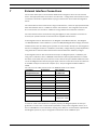
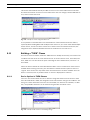
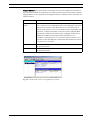
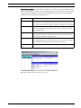
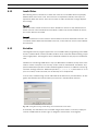
SFT-INTSRV - Integration Server
Version 1.11
en
User Manual
AutoDome, Bilinx, Bosch, the Bosch logo, DiBos, FastAddress and VIDOS are registered trademarks of Bosch Security Systems, inc.
The following trademarks are registered with the United States Patent and Trademark Office:
Pentium is a registered trademark of Intel Corporation
.NET, DirectX, Internet Explorer, Microsoft, Windows, Windows 2000, Windows NT, Windows VIsta, and Windows XP are registered trademarks of
Microsoft Corporation
Due to the nature of this material, this document refers to numerous hardware and software products by their trade names, In most, if not all
cases, these designations are claimed as trademarks or registered trademarks by their respective companies in the United States of America. It is
not this publisher’s intent to use any of these names generically. The reader is therefore cautioned to investigate all claimed trademark rights before using any of these names other than to refer to the product described.
iv
en |
SFT-INTSRV Integration Server
Preface
This guide describes how to install the SFT-INTSRV Integration Server.
Audience
This guide is intended for qualified installation and service personnel who are familiar with the applicable national
and local electrical codes.
Document Conventions
Convention
Bold
Italic
Underline
courier
Meaning
Denotes a part, item, or assembly.
Denotes a reference to another paragraph, figure or table.
Used to emphasize a point.
Denotes the actual name of an object, the exact code that should be typed or a message
returned from a system.
Symbols
You may encounter these symbols within the document. Explanatory text accompanies each symbol, which provides
additional information detailing the operation or highlighting safety information.
i
!
!
NOTICE! Notices inform you of essential but non-critical information. Read these messages
carefully as any directions or instructions contained therein can help you avoid making
mistakes.
CAUTION! Cautionary messages provide critical information that help you reduce the chance
of losing data or damaging the system. Please heed these messages.
WARNING! Warnings highlight information, that if overlooked may cause damage to the
system or result in personal injury. Take warnings seriously.
DANGER! Danger messages denote the presence of electrical equipment that may cause
electric shock or electrocution. Take care when you see this symbol to avoid serious injury or
death.
F01U065436 | 1.0 | 2007.03
User Manual
Bosch Security Systems, Inc.
SFT-INTSRV Integration Server
| en
v
Customer Support and Service
If this unit needs service, contact the nearest Bosch Security Systems Service Center for authorization to return and
shipping instructions.
Service Centers
USA
Phone: 800-366-2283 or 585-340-4162
Fax: 800-366-1329
Email: [email protected]
Technical Support
Phone: 800-326-1450
Email: [email protected]
CCTV Spare Parts
Phone: 800-894-5215 or 408-957-3065
Fax: 408-935-5938
Email: [email protected]
Canada
Phone: 514-738-2434
Fax: 514-738-8480
Europe, Middle East & Asia Pacific Region
Phone: 44 (0) 1495 274558
Fax: 44 (0) 1495 274280
Email: [email protected]
For additional information, see www.boschsecurity.com
Related Publications
Refer to the latest Bosch Security Systems, Inc. Databook for the most up-to-date datasheets. To obtain a copy of
the Databook, please contact your local Bosch representative.
You can also visit the Bosch Security Systems World Wide Web site at: http://www.boschsecurity.com to view a current listings of our publications.
Bosch Security Systems, Inc.
User Manual
F01U065436 | 1.0 | 2007.03
vi
en | Table of Contents
SFT-INTSRV - Integration Server
Table of Contents
1
Unpacking
1
1.1
Parts List
1
2
Description
1
2.1
Features
2
3
Minimum System Requirements
2
4
LTC 8050/00 README File
2
5
Installation
3
6
Security Device Attachment
3
7
External Interface Connections
4
8
Operation
5
8.1
Running the Software
5
8.2
Changing Login Password
5
8.3
User Profile Dialog Box
6
8.4
Configuration Document
6
8.5
Program Navigation
7
8.6
Getting Help
7
8.7
Menu Commands
7
8.8
Devices
9
8.9
Rules
10
8.9.1
Creating the First RULE
10
8.10
Building an "IF" Clause
11
8.10.1
Device Options in IF Clauses
11
8.10.2
Extended Truth Time
14
8.11
Building a "THEN" Clause
15
8.11.1
Device Options in THEN Clauses
15
8.12
Invalid Rules
19
8.13
Variables
19
8.14
Diagnostics
20
F01U065436 | 1.0 | 2007.03
User Manual
Bosch Security Systems, Inc.
SFT-INTSRV Integration Server
1
Unpacking | en
1
Unpacking
This equipment should be unpacked and handled with care. If an item appears to have been
damaged in shipment, notify the shipper immediately.
Verify that all the parts listed in the Parts List below are included. If any items are missing,
notify your Bosch Security Systems Sales or Customer Service Representative.
The original packing carton is the safest container in which to transport the unit and must be
used if returning the unit for service. Save it for possible future use.
1.1
Parts List
Although the SFT-INTSRV software package contains several components, only the following
items are applicable to the Integration Server software. The following table lists the parts
included:
2
Quantity
Part
1
Model number of unit
1
Installation manual
4
"SFT-INTSRV" CD-ROM containing LTC 8050/00 Integration Server software
1
Software security key (USB dongle)
Description
The Integration Server is a PC based software package used to integrate multiple systems that
are not ordinarily compatible. These systems can include Video Switchers, Point of Sale systems, Burglar/Fire Alarms, Access Control systems, and HVAC systems.
Devices to be controlled can communicate 3 ways:
1.
RS-232 - Up to 16 COM Ports are supported. The command codes for each device must
be supplied by the manufacturer or known to the installer, and are programmed into the
Integration Server. The Integration Server listens to the COM Port for the specific strings
of data programmed by the installer. The server can also transmit preprogrammed strings
of data from the COM Port to control devices.
2.
Digital I/O - A Digital I/O card (National Instruments™ # PC-DIO-24) can be installed in the
PC. This card can either control relays wired to external devices, or can monitor relays
controlled by external devices.
3.
Directly to an Allegiant Switcher via the Master Control Software (LTC 8059/00) or the
Allegiant GUI package (LTC 8850/00) - If the PC is running either of these programs in
conjunction with the Integration Server, communication to the Allegiant Switcher can
take place without additional external wiring.
The Integration Server Software is programmed to recognize events as they occur on each system, based on one of the methods above, then react to those events by sending commands to
another system. Programming is done using Rules. Rules are easy to understand clauses, written by the installer, and stored in the program. Rules can be as simple as a single reaction to a
single event. They can also be more complex, to include multiple reactions to multiple events
under multiple conditions, such as time of day or a range of dates.
The Integration Server is designed with advanced features to simplify operation and configuration. An integrated COM Port data viewer can be used to monitor the communication traffic
coming in and going out of the PC’s COM Ports. This tool not only simplifies the design stage
Bosch Security Systems, Inc.
User Manual
F01U065436 | 1.0 | 2007.03
2
en | Minimum System Requirements
SFT-INTSRV Integration Server
of an initial configuration, it also functions as a powerful diagnostic aid. In addition, the software supports the ability to automatically run a pre-selected configuration file upon boot-up
of the PC. This feature eliminates the need for manual restarts in the event of a PC power
interruption.
2.1
Features
–
Allows communication between normally incompatible systems
–
Various communication methods, including RS-232, digital I/O, and directly to Allegiant
–
Interfaces with all Allegiant Series Systems
–
Can log any or all events onto a PC hard drive
–
Integrated COM Port data viewer
Server software
3
Minimum System Requirements
Before using the Integration Server Software, make sure that the host computer meets the following:
Minimum System Requirements
–
PC platform with mouse and keyboard
–
Pentium® 800 MHz CPU and SVGA monitor
–
128 Mb RAM (with Windows NT 2000 or XP)
–
512 Mb RAM (with Windows Vista)
–
250 Mb fixed drive space
–
CD-ROM drive
–
USB port
Operating System
–
Windows NT (with service pack 6a or greater)
–
Windows 2000 (service pack 4 or later)
–
Windows XP Professional (service pack 2 or later)
–
Windows Vista Business v6.00
PC Ports Required (Minimum)
–
1 USB
–
1 Serial
–
(Additional serial ports required if multiple systems are being controlled – up to 16 supported)
Slot Type for Optional Data I/O Card
–
ISA (if software will be used with National Instruments™ # PC-DIO-24 Data I/O card)
Before using the Integration Server Software, users should become familiar with the external
devices being connected to the PC running the Integration Server Software, as well as their
personal computer and operating system software. Users having Windows administrator level
access is required to install the software.
4
LTC 8050/00 README File
Occasionally, revisions are made to the Integration Server software that are not reflected in
this manual. These changes are described in the LTC 8050/00 README file. This file should be
read whenever a new version of the LTC 8050/00 is installed. There is an icon for the README
file in the LTC 8050/00 Start menu group.
F01U065436 | 1.0 | 2007.03
User Manual
Bosch Security Systems, Inc.
SFT-INTSRV Integration Server
5
Installation | en
3
Installation
Insert the CD and wait for the installation dialog box to appear. If the installation dialog box
does not appear, manually browse the CD and run the Setup.exe. Once the dialog box
appears, click the Integration Server's Install button. The Installation Wizard will guide you
through the entire process. If the Integration Server will be used with an Allegiant Switcher,
the LTC 8059/00 Master Control Software or the LTC 8850/00 Graphical User Interface (GUI)
Software will also need to be installed on the PC. Install the LTC 8059/00 Master Control Software or LTC 8850/00 GUI Software before installing the LTC 8050/00 Integration Server Software.
6
Security Device Attachment
Before the program will run on the host computer, the hardware security key must be connected to an available USB port of the computer. If necessary, locate this port with the help of
the hardware manual that comes with the host computer. Push the security key into place. Its
LED will light. If the LTC 8059/00 Master Control Software will be used on the same PC as the
Integration Server, it is only necessary to connect the dongle key supplied with the Integration
Server.
If the security device is not connected, the Integration Server Software will operate in a demo
mode. While in demo mode, the software will not check to see if any Rules are TRUE, therefore, no actions will result. A dialog box, reminding the user it is in demo mode, appears periodically. Access to other features will be available, so configurations may be created and
saved to disk before final site integration takes place.
Bosch Security Systems, Inc.
User Manual
F01U065436 | 1.0 | 2007.03
4
7
en | External Interface Connections
SFT-INTSRV Integration Server
External Interface Connections
For functions that require communication between the Integration Server and an external
device, the appropriate data connections must be made. Configuration and verification of the
connections should be completed before trying to interface the device with the Integration
Server.
For external devices that communicate using a serial interface, connect an appropriate RS-232
data cable between the PC’s COM Port and the external device. The Integration Server will
also communicate over virtual PC COM Ports using network based ethernet serial hubs.
For external devices that communicate using the Digital I/O card, install the card in the PC
and verify its operation based on the instructions supplied with the device.
If the Integration Server will interface to an Allegiant Series Matrix Switcher, the Allegiant
LTC 8059/00 Master Control Software (or the LTC 8850/00 Allegiant GUI Package) should be
installed on the same PC. Although it is possible to communicate directly from the Integration
Server to an Allegiant via the PC’s COM Port (see below), configuration is greatly simplified by
using the built-in communication interface that exists between the software packages.
If the Integration Server will communicate directly to an Allegiant system’s CONSOLE port
using a PC’s COM Port, the LTC 8506/00 serial interface cable supplied with the LTC 8780
should be used. Attach the 9-pin connector on the cable to the port labeled CONSOLE on the
rear of the Allegiant main CPU bay. Plug the 9-pin connector on the other end of the cable into
an available serial port on the host computer (PC). This port might be labeled COM1 or
COM2.
For reference, the cable pinouts of the LTC 8506/00 cable are as follows:
9-Pin Male
Designation
9-Pin Female
(Allegiant Side) Pin
(PC Side) Pin
1
Chassis GND
None
2
Receive Data
3
3
Transmit Data
2
4
CTS
1, 7
5
RTS
8
6
No Connection
None
7
Data GND
5
8
No Connection
None
9
No Connection
None
(jumper pins 4 & 6)
In order for serial communications to operate properly, the Allegiant system must be programmed to use the same communication parameters setup in the Integration Server (or in
the LTC 8059 Master Control Software, if being used). Refer to documentation supplied with
the Allegiant System for proper configuration information of the CONSOLE port.
F01U065436 | 1.0 | 2007.03
User Manual
Bosch Security Systems, Inc.
SFT-INTSRV Integration Server
Operation | en
8
Operation
8.1
Running the Software
5
The installation procedure creates a Start menu icon under Bosch Integration Server. Click
this icon to run the software. Only one instance of the Integration Server application should
be run at a time. If necessary, multiple documents can be configured and will operate simultaneously as long as there are no resource conflicts. For example, each document needs to
specify unique COM ports, log files, etc.
When run, the program will open and the Log In dialog box will appear. If this is the first time
that the program is being run, the Installer name should be selected when prompted for a
username. The default password for Installer is 1.
Fig. 8.1
Log In Dialog Box
Default passwords for each privilege level have been entered at the factory and are as follows:
8.2
Privilege Level
Password
Installer
1
Administrator
2
Operator
3
Changing Login Password
If desired, you can change the log in password to prevent unwanted user access. Open the
File menu and then select Change Password option.
Fig. 8.2
Bosch Security Systems, Inc.
Change Password Dialog Box
User Manual
F01U065436 | 1.0 | 2007.03
6
8.3
en | Operation
SFT-INTSRV Integration Server
User Profile Dialog Box
By default, the Integration Server Software utilizes three (3) privilege levels:
Installer:
Has access to all program features.
Administrator:
Has access to all program features, but not to all User Profile settings.
Operator:
Cannot log in to the Integration Server.
Installers and Administrators can utilize the User Profile dialog box option in the File menu to
delete or add additional user names to the log in list. Each user can be assigned a privilege
level of installer, administrator, or operator. Installers can also assign the privilege of Installer
to other users. Administrators can alter all entries except those of an installer.
Fig. 8.3 User Profile Dialog Box
8.4
Configuration Document
For first time setup, a new configuration document must be created; from the File menu,
select New. The system will generate the default filename IntSvr1. The main window will
appear as follows:
Fig. 8.4 Main Window
F01U065436 | 1.0 | 2007.03
User Manual
Bosch Security Systems, Inc.
SFT-INTSRV Integration Server
8.5
Operation | en
7
Program Navigation
The Integration Server Software is designed to provide the user an ergonomic look and feel.
Many configured items can be edited simply by double clicking on the selected clause. Alternatively, right clicking on an item will bring up an option menu displaying other selections
available to the user.
8.6
Getting Help
The Integration Server Software provides extensive on-line help. The on-line help can be
accessed in several ways. Selecting Help Topics from the Help menu will display a list of topics available. In any of the help screens, underlined words or phrases indicate that more help
is available. Clicking on the underlined words will display help for that topic. The Integration
Server Software also provides context sensitive help. When the F1 function key is pressed,
help for the currently selected item will be presented. Alternatively, the [Context Help] button
in the toolbar can be used.
When this button is clicked, the cursor will change to an arrow/question mark. When this cursor is active, clicking on any item in the software window will call up help for that item.
8.7
Menu Commands
The Integration Server menus are described as follows. Some include a toolbar button. Clicking on the toolbar button is equivalent to selecting the corresponding menu item.
Item
Description
New
Creates a new Integration Server document.
Open
Opens an existing Integration Server document.
Close
Closes an opened Integration Server document.
Save
Saves an opened Integration Server document using the same file
name.
Save As
Saves an opened Integration Server document to a specified file
name.
User Profile
Displays the User Profile dialog box from which user information
(names, passwords, and group memberships) can be managed and
users can be created, modified, or deleted.
Log In
Log in as a new user.
Change Password Change password of current user.
Select File to
Places a shortcut in the Windows Startup group for an Integration
Launch at Win-
Server file. When a file is selected, the menu option to "Run Hidden
dows Startup
when Launched by Opening .isd File" will automatically be checked.
Uncheck the menu item and delete the file name from the Windows
Startup folder if this action is not desired.
Run Hidden when
When checked, the Integration Server will run in the background
Launched by
when launched by opening an Integration Server configuration file. A
Opening .isd File
user will have to click on the task bar icon and log on before the Integration Server application will become visible.
Hide Application
Log off and hide application. A user will have to click on the task bar
icon and log on before the Integration Server will become visible.
Bosch Security Systems, Inc.
User Manual
F01U065436 | 1.0 | 2007.03
8
en | Operation
SFT-INTSRV Integration Server
Print
Prints a document.
Print Preview
Displays the document on the screen as it would appear printed.
Print Setup
Selects a printer and printer connection.
Recently Opened
Lists the names of the four most recently used files. Selecting one of
Files List
these entries will open the selected file.
Exit
Exits the Integration Server.
The Edit Menu offers the following commands:
Item
Description
Cut
Deletes data from the document and moves it to the clipboard
Copy
Copies data from the document to the clipboard
Paste
Pastes data from the clipboard into the document
The Devices Menu offers the following commands:
Item
Description
Add
Add a new device
View
View configured devices
The Rules Menu offers the following commands:
Item
Description
Add
Add a new Rule
Edit
Edit the selected Rule
Remove
Remove the selected Rule
The Clause Menu offers the following commands:
Item
Description
Add
Add a new IF / THEN clause
Edit
Edit the selected clause
Remove
Remove the selected clause
The View Menu offers the following commands:
Item
Description
Toolbar
Shows or hides the toolbar
Status Bar
Shows or hides the status bar
The Window Menu offers the following commands:
Item
Description
Cascade
Arranges windows in an overlapped fashion
Tile
Arranges windows in non-overlapped tiles
Window 1, 2, ...
Goes to specified window
F01U065436 | 1.0 | 2007.03
User Manual
Bosch Security Systems, Inc.
SFT-INTSRV Integration Server
Operation | en
9
The Help Menu offers the following commands:
Item
Description
ASCII Table
Display a table that shows the ASCII characters along with their decimal and hexadecimal value
Contents
Displays a list of available help topics
About
Displays the Integration Server Software copyright and version number information
8.8
Devices
A new configuration will not contain any information related to the devices being integrated.
Devices must be defined before any Rules (see below) can be set. To display the Devices dialog box, select Devices from the menu, and select View.
Add the first device by selecting Device from the menu, then select Add. The following dialog
box is displayed:
Fig. 8.5
Devices Dialog Box
Select the type of device for the first device. The four (4) device types are:
COM Port:
Select this for any external device that will communicate with the PC
via RS-232 serial communications.
Allegiant Switcher:
Select this if the Allegiant Matrix Switcher Software (LTC 8850/00
Graphical User Interface or LTC 8059/00 Master Control Software) is
installed on the same PC as the Integration Server, and will be used
to communicate with an Allegiant Series Video Switcher.
Log File:
Select this to create a text file and fill it with text relating to various
events (you can create multiple log files and separately define the
contents of each).
Digital I/O Card:
Select this if the PC running the Integration Server Software contains
a National Instruments I/O card (model # PCDIO-24) to be used to
communicate with some outside device(s).
To view the status of configured devices, select Devices, then View from the menu.
Bosch Security Systems, Inc.
User Manual
F01U065436 | 1.0 | 2007.03
10
en | Operation
SFT-INTSRV Integration Server
Fig. 8.6 Devices Status Box Example
8.9
Rules
Rules are groups of clauses that define how and when devices will be used. These Rules are
defined by using IF and THEN clauses (explained later). In its simplest form, a Rule could be
read: IF event X occurs on device A, THEN cause event Y to occur on device B.
Multiple IF clauses can be combined to make more specific requirements. THEN clauses can
also be combined to create multiple events. For example, a Rule could look something like:
IF event X occurs on device A and IF event Y occurs on device B, THEN cause event Z to occur
on device C and cause event W to occur on device D.
IF clauses known as Qualifiers can be used to prevent a Rule from taking place unless the
qualifying condition has been met. An example of a Qualifier clause may include ranges of date
and time to allow clauses to be entered such as:
IF event X occurs on device A between Monday and Friday THEN cause event Y to occur on
device B.
8.9.1
Creating the First RULE
From the Rules menu, select Add, or select the pane containing the Rules list and click the +
icon on the toolbar. When prompted, enter a name for the new Rule that will help you identify
its function. Note that the default mode for the Rule is enabled. To temporarily disable a Rule,
uncheck the enabled box next to the description.
Once the Rule has been named, add the necessary clauses to the Rule, with the IF clauses
first.
Fig. 8.7 RULE Definition Example
Once you write a Rule, the software immediately begins checking its IF clauses (see below).
F01U065436 | 1.0 | 2007.03
User Manual
Bosch Security Systems, Inc.
SFT-INTSRV Integration Server
8.10
Operation | en
11
Building an "IF" Clause
IF clauses are either Action clauses (based on an event) or Qualifier clauses (based on a condition). Every Rule needs at least one Action clause. Qualifier clauses are depicted with Q next
to them.
From the Clauses menu, select Add, then IF. You can also select the pane containing the list of
IF clauses and click the + icon on the toolbar. Select the Device that will be associated with
this Rule. Choices always include the built-in Date/Time and Auto Run options, but other
choices will be available only if the associated Device has been installed. Once the Device is
selected, a list of possible events or clauses is displayed for selection.
8.10.1
Device Options in IF Clauses
COM Port: This function will activate an event based on data strings received by a COM Port.
The software will continuously monitor the data being received by the COM Port and react
immediately if the data matches the user defined string.
Fig. 8.8
Example IF Clause for Receiving Simple String
Wildcards can be used to match strings where some characters vary. The question mark (?)
wildcard matches a single character.
Example: b?ll - matches ball, bell, bill
The asterisk (*) wildcard matches one or more characters.
Example: b*n - matches bin, born, begin
Notes: The asterisk wildcard can not be the first or last character to match.
To match a question mark or asterisk character, enclose the character in brackets.
Example: [?] matches the question mark character.
The characters that match the wildcard(s) will be stored in a Rule variable. (See
Section 8.13: Variables.)
Non-printable characters like those below can be entered using brackets and ASCII codes.
–
SX (Ctrl-B) - [2]
–
EX (Ctrl-C) - [3]
–
LF (Ctrl-J) - [10]
–
CR (Ctrl-M) - [13]
For a complete list of non-printing characters, refer to the ASCII Table found in the Help menu.
Bosch Security Systems, Inc.
User Manual
F01U065436 | 1.0 | 2007.03
12
en | Operation
SFT-INTSRV Integration Server
Fig. 8.9 Example Receive String with Wildcards and Non-printing Characters
Allegiant Switcher: This function will activate an event based on various status changes occurring in an Allegiant Switcher. Changes include the following events and/or conditions:
Event
Type
Description
Monitor Switched Action
This event takes place when an Allegiant monitor
Camera
switches to a new camera. Specify the monitor(s) and
the camera(s).
Alarm Activated
Action
This event occurs when an Allegiant Alarm occurs.
Specify which alarm(s).
Alarm Deactivated Action
This event occurs when an Allegiant Alarm is deactivated. Specify which alarm(s).
Camera Video Loss Action
This event occurs when an Allegiant Camera loses
video. Specify which camera(s).
Camera Video
Action
This event occurs when an Allegiant Camera has its
Restored
video restored. Specify which camera(s).
Alarm is Currently Qualifier
This Qualifier checks if a specific Allegiant Alarm(s) is
Active
currently active.
Alarm is Not Cur-
Qualifier
This Qualifier checks if a specific Allegiant Alarm(s) is
rently Active
NOT currently active.
Camera has Video Qualifier
This Qualifier checks if a specific Allegiant Camera(s)
currently has video.
Camera does Not
Qualifier
have Video
This Qualifier checks if a specific Allegiant Camera(s)
does NOT currently have video.
Camera Lock Acti- Action
This event occurs when an Allegiant keyboard Operator
vated
activates a camera lock. Specify which camera(s).
Camera Lock
Action
This event occurs when an Allegiant keyboard Operator
Deactivated
deactivates a camera lock. Specify which camera(s).
Monitor Lock Acti- Action
This event occurs when an Allegiant keyboard Operator
vated
activates a monitor lock. Specify which monitor(s).
Monitor Lock
Deactivated
Action
This event occurs when an Allegiant keyboard Operator
deactivates a monitor lock. Specify which monitor(s).
In many cases, it may be desirable to use a list of numbers in IF clauses to match against multiple possibilities. The list should be entered using commas and dashes. For example, the
F01U065436 | 1.0 | 2007.03
User Manual
Bosch Security Systems, Inc.
SFT-INTSRV Integration Server
Operation | en
13
series ‘1-5,7,9’ can be used to test for several camera numbers that the IF clause will monitor
for activity.
When a list is used, the actual camera number that makes this clause TRUE will be stored in a
Rule variable (see Section 8.13: Variables.)
Fig. 8.10 Example IF Clause Using Number List Feature
Digital I/O Card Interface: This function will activate an event based on status changes occurring on the external lines of the Digital I/O card. Changes include the following events and/or
line conditions:
Event
Type
Description
Line Change from
Action
This event occurs when an input line switches from 0
Low to High
to +5V, or logical false to logical true. Select which
line(s).
Line Change from
Action
High to Low
This event occurs when an input line switches from +5V
to 0, or logical true to logical false. Select which
line(s).
Line Change
Action
(either way)
This event occurs when an input line switches state
either way (+5V to 0V, or 0V to +5V). Select which
line(s).
Line is High
Qualifier
This Qualifier checks if a specific line is High or at +5V
(logical True). Select which line(s).
Line is Low
Qualifier
This Qualifier checks if a specific line is Low or at 0V
(logical False). Select which line(s).
Port Pattern
Action
Changed
This event occurs when any bit(s) within the port (a
group of 8 bits) have changed, or if the port changes to
a specific pattern. You can specify the port and the pattern. Enter a "-1" for the pattern if you want to match
any port pattern.
Port Pattern is a
Certain Value
Bosch Security Systems, Inc.
Qualifier
This qualifier checks if a specific pattern is currently on
the specified port.
User Manual
F01U065436 | 1.0 | 2007.03
14
en | Operation
SFT-INTSRV Integration Server
Fig. 8.11 Example IF Clause Using Digital I/O Card
Date/Time: This function will activate an event based on the specified date, time or interval.
Available options include the following:
Event
Type
Description
At Specific Date
Action
This event occurs at the specified date and time.
and Time
At Specific Interval Action
This event occurs at the specified date and time, and
will repeat at the specified time interval.
In-between Times
Qualifier
This Qualifier checks if the current time is within the
specified times.
In-between Dates
Qualifier
This Qualifier checks if the current date is within the
specified date range.
In-between Days of Qualifier
This Qualifier checks if the current day is within the
the Week
specified date range.
Auto Run: This function will activate an event when a configuration file is first opened.
!
8.10.2
CAUTION! If the Integration Server file contains an Allegiant Switcher device, the clause will
be true after the Allegiant Switcher goes on line.
Extended Truth Time
Most Action clauses have an option called Extended Truth Time. Since multiple action clauses
can be combined within a Rule, and all actions within that Rule cannot take place simultaneously, it is necessary to extend the time that an event is recognized by the system as having
occurred.
The example screen below has two action IF clauses:
Digital Card Line changes from LOW to HIGH, line A4, Extended Truth time = 30 seconds (as
indicate by the "(30)" under the Detail Section).
Allegiant Camera Video Loss, camera 2, No Extended Truth.
The first IF clause has an extended truth time of 30 seconds. The second IF clause does not
have an extended truth time.
F01U065436 | 1.0 | 2007.03
User Manual
Bosch Security Systems, Inc.
SFT-INTSRV Integration Server
Operation | en
15
This means that this Rule will only be TRUE if camera 2 loses video within 30 seconds after
line A4 becomes HIGH. If camera 2 looses video before the Line changes, the Rule will NOT be
true, and no action will result.
Fig. 8.12 Example IF Clause Using Extended Truth
It is important to understand the uses and limitations of the Extended Truth time feature,
especially when building Rules with multiple Action clauses. If you create a Rule with multiple
Action clauses, and do not select at least one of them to have an Extended Truth time, the
Integration Server Software will label the Rule as invalid and an error will occur.
8.11
Building a "THEN" Clause
Once the IF clause is written, define the THEN clause to identify the action(s) to be taken if all
conditions set forth in the IF clause have been met. From the Clauses menu, select Add, and
then, THEN. You can also select the pane containing the list of THEN clauses, and click + on
the toolbar.
Select the device that will be associated with this Rule. Choices include most of the Devices
available when entering IF clauses, plus miscellaneous utilities and the option to write to a
Log File. Some choices are only visible if the associated Device has been installed. Once the
Device is selected, a list of possible events or clauses is displayed for selection.
8.11.1
Device Options in THEN Clauses
Com Port: This action allows the user to define a string that will be sent out the PC’s COM
Port. When this Rule is TRUE, the Integration Server will send the string to the COM Port. The
string can contain information stored in a local variable (see Section 8.13: Variables). In addition, non-printable characters can be entered using brackets and ASCII codes.
Fig. 8.13 Example THEN Clause for Transmitting Strings
Bosch Security Systems, Inc.
User Manual
F01U065436 | 1.0 | 2007.03
16
en | Operation
SFT-INTSRV Integration Server
Allegiant Switcher: This option allows commands to be sent to an Allegiant Series Switcher.
When this Rule is TRUE, the Integration Server will send the specified command through the
Allegiant Master Control Software to the Allegiant Switcher. Available actions include the following functions:
Event
Description
Send CCL Com-
This event sends the specified "CCL" command to the Allegiant system.
mand
"CCL" commands are a standardized ASCII based language used by the
Allegiant series switchers that allow them to be controlled using an
external serial interface. If you are not familiar with using Allegiant CCL
commands, complete information can be found in the "Allegiant Main
CPU Interface Software Command Console Language" manual that is
available for download from www.boschsecuritysystems.com.
In addition, the dialog box for CCL command creation includes a "CCL
generator" button that will open a wizard that will simplify the creation
of common CCL commands.
Set Camera Lock
This event sends a command that places a User based priority lock on
the specified camera.
Set Monitor Lock
This event sends a command that places a User based priority lock on
the specified monitor.
Fig. 8.14 Example THEN Clause for Sending Allegiant Commands
F01U065436 | 1.0 | 2007.03
User Manual
Bosch Security Systems, Inc.
SFT-INTSRV Integration Server
Operation | en
17
Log File: This function will allow the user to define text to be written to a Log File. The message can contain information stored in a local variable (see Section 8.13: Variables). When
selecting a log file name, make sure that it is a name that will be unique to the Integration
Server document. Do not select a file name that might be accessed by another program.
Fig. 8.15 Example THEN Clause for Writing to a Log File
Digital I/O Card Interface: This function allows the user to define the logic states of the external lines on the Digital I/O card. You can set a specific bit HIGH or LOW, or send a specific bit
pattern. This is useful to turn on/off relays. Available actions include the following functions:
Event
Description
Make Line HIGH
This event sets the specified output line of the Digital card from 0 to
+5V, or logical false to logical true.
Make Line LOW
This event sets the specified output line of the Digital card from +5V to
Set Port Pattern
This event sets the output lines of the Digital card to a specified pattern.
0, or logical true to logical false.
This allows all 8 of the outputs to be set to either logic level (0 or +5V)
using a single command.
Fig. 8.16 Example THEN Clause for Controlling Digital I/O Card
Bosch Security Systems, Inc.
User Manual
F01U065436 | 1.0 | 2007.03
18
en | Operation
SFT-INTSRV Integration Server
Miscellaneous Utilities: The Miscellaneous Utilities are used for more advanced Rule writing. A
basic understanding of software programming is helpful, but not required. The On-line Help
Section within the Integration Server provides additional information and some examples.
Available actions include the following functions:
Event
Description
Set Variable
This function saves either a specific value, or the result of a mathematical equation, to the specified variable. The mathematical equation can
also contain values stored in other variables. See Section 8.13: Variables.
Delay
Specify the amount of time for the server to wait before completing the
rest of the THEN clause. The time can be in hours, minutes, seconds,
and/or milliseconds.
Begin Loop
This is the beginning of a loop in which THEN clauses are repeated for a
predetermined number of iterations. Define the number of iterations,
and an index variable for other purposes.
End Loop
This defines the end of the loop. All THEN clauses prior to this statement
but following Begin Loop will repeat based on the criteria in the Begin
Loop definition. Subsequent clauses will not be repeated.
Enable/Disable
This clause allows Rules to be enabled or disabled.
Rule
Fig. 8.17 Example THEN Clause Using Loop Function
F01U065436 | 1.0 | 2007.03
User Manual
Bosch Security Systems, Inc.
SFT-INTSRV Integration Server
8.12
Operation | en
19
Invalid Rules
When writing clauses, the title bar of either the IF clauses or the THEN clauses may display
INVALID RULE and a reason code. These reasons are explained as follows, and require an
adjustment within the clauses. Once the correction is made, the title bar no longer displays
this message.
Reason 1
A Rule must have at least one Action IF clause. Qualifier IF clauses are only tested when an
Action IF clause in the same Rule becomes TRUE. If a Rule only contains Qualifier IF clauses,
the clauses will never be tested.
Reason 2
If a Rule contains two or more Action IF clauses that do not have an Extended Truth Time, it is
considered invalid. Without the Extended Truth Time, no two Action IF clauses can be TRUE at
the same time.
8.13
Variables
The Integration Server program supports the use of Variables when programming IF and THEN
clauses. Variables allow countless, flexible variations of the same Rule without writing complicated, lengthy Rules. The Integration Server allows 50 variables for this purpose, identified as
1-50.
Variables are used during THEN clause Loops (see Miscellaneous Utilities) to keep track of the
number of times a loop has occurred. They are also used for mathematical calculations. Supported mathematical operators include standard algebraic functions, in addition to many trigonometric and logic functions. Relational operators ( >, <, <=, >=, ==, <>) that return a 1 or a 0
(for true or false) can also be used (see On-line Help for a complete list).
In most cases, variables being used in mathematical calculations are preceded with a "%" designator that indicates the value should be processed as a standard ASCII character.
Fig. 8.18 Dialog Box Showing Variable Being Used for Mathematical Calculation
Occasionally, it is desirable to treat a variable using its base number. To do this, simply precede the variable with the number sign "#" designator instead of the "%" designator.
Bosch Security Systems, Inc.
User Manual
F01U065436 | 1.0 | 2007.03
20
en | Operation
SFT-INTSRV Integration Server
Fig. 8.19 Example THEN Clause Using Variables
The Integration Server also supports the use of numeric base calculations. To use expressions
involving binary, octal, or hexadecimal numbers, simply precede the character with a "#" symbol followed by "b", "o", or "h" for binary, octal, or hexadecimal, respectively.
8.14
Diagnostics
The Integration Server includes a COM Port data viewer to help diagnose devices connected
to a COM Port. To display the COM Port data viewer:
1.
Select the desired COM Port device in the Devices dialog box.
2.
From the Device menu, select Display.
3.
The COM Port data viewer shows the data going in and going out of a PC’s COM Port.
Data coming into the PC’s COM Port is shown in blue color, and data going out is shown
in red color.
There are three (3) ways to view the data; ASCII representation only, hexadecimal values only,
or both. If you highlight text in one view, the corresponding data is highlighted in the other
view.
ASCII characters that are non-printable will be displayed as a question mark. To determine
which character it actually is, highlight the question mark and look at the data highlighted in
the hexadecimal view.
The ASCII Table found in the Help menu may also prove useful when you need to decipher the
data being received by a COM Port.
F01U065436 | 1.0 | 2007.03
User Manual
Bosch Security Systems, Inc.
SFT-INTSRV Integration Server
Operation | en
21
Fig. 8.20 COM Port Data Viewer Window
Bosch Security Systems, Inc.
User Manual
F01U065436 | 1.0 | 2007.03
Americas:
Bosch Security Systems
130 Perinton Parkway
Fairport, New York, 14450
USA
Phone
+1 800 289 0096
Fax
+1 585 223 9180
www.boschsecurity.us
Europe, Middle East, Asia:
Bosch Security Systems B.V.
Postbus 80002
5600 JB Eindhoven
Phone:
+31 40 2577 200
Fax:
+31 40 2577 202
[email protected]
www.boschsecurity.nl
www.boschsecurity.com
© Bosch Security Systems, Inc., 2007; F01U065436 | 1.0 | 2007.03
www.boschsecurity.com
Asia-Pacific:
Bosch Security Systems Pte Ltd.
38C Jalan Pemimpin
Singapore 577180
Phone
+65 6319 3450
Fax
+65 63139 3499
www.boschsecurity.com