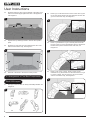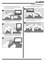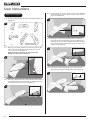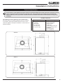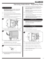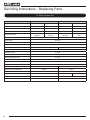
1
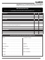
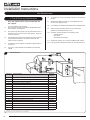
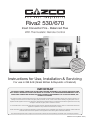
Riva2 530/670
Inset Convector Fire - Balanced Flue
With Thermostatic Remote Control
ANTw:,
T
R
O
o
foll
IMP
to
asy
ideo
ep v
to
by st
p
e
how
t
s
s on
our
y
tion
c
u
instr
maintain go to
d
e an
stem
operat mote sy
re
o tv
azco
For e
G
.Gazc
www
.
Instructions for Use, Installation & Servicing
For use in GB & IE (Great Britain & Republic of Ireland).
IMPORTANT
THE OUTER CASING, FRONT AND GLASS PANEL BECOME EXTREMELY HOT DURING OPERATION AND
WILL RESULT IN SERIOUS INJURY AND BURNS IF TOUCHED. IT IS THEREFORE RECOMMENDED THAT A
FIREGUARD COMPLYING WITH BS 8423:2002 IS USED IN THE PRESENCE OF YOUNG CHILDREN, THE
ELDERLY OR INFIRM.
This product contains a heat resistant glass panel. This panel should be checked during Installation and at each servicing interval. If any
damage is observed on the front face of the glass panel (scratches, scores, cracks or other surface defects), the glass panel must be
replaced and the appliance must not be used until a replacement is installed. Under no circumstances should the appliance be used if any
damage is observed, the glass panel is removed or broken.
It is essential that ALL of the screws that retain the glass frame are replaced and tightened correctly. Under no circumstances should the
appliance be operated if any of these screws are loose or missing.
These Instructions must be left with the appliance for future reference and for consultation when servicing the appliance. Please make the
customer aware of the correct operation of the appliance before leaving these instructions with them.
The commissioning sheet found on Page 3 of this Instruction manual must be completed by the Installer prior to leaving the premises.
PR2010 Issue 2 (March 2014)
Contents
Riva2 530/670 Balanced Flue
Covering the following models:
Gas Type
RIVA2 530
RIVA2 670
NG
134-313
134-247
LPG
134-728
134-653
Appliance Commissioning Checklist.......................3
User Instructions........................................................4
Installation Instructions...........................................12
Technical Specifications ........................................................... 12
Site Requirements..................................................................... 14
Installation................................................................................. 21
Commissioning.......................................................................... 28
Servicing Instructions..............................................29
Fault Finding.............................................................................. 29
How To replace Parts................................................................ 31
Basic Spare Parts List .............................................................. 36
Service Records........................................................................ 37
2
To receive your Extended Warranty your Gazco appliance must have
been purchased from our Expert Retailer Network and registered within
one month of purchase or installation. Please note that all warranties
are effective from the date of purchase. Any Gazco product purchased
outside of our Extended Retailer Network, or not registered within the
stated time will carry a standard 12 month warranty.
It is a condition of the Extended Warranty that the installation
complies with the relevant Building Regulations and is carried out
by a suitably trained and qualified individual (GasSafe in the UK or
equivalent in other countries) with the certificate of installation and the
Commissioning Report on Page 3 completed and retained by the end
user.
Full terms and conditions are detailed in the Warranty Statement on
the Gazco website www.gazco.com. In the event of any conflict of
information the wording on the website shall prevail.
Important Note: Should any problems be experienced with your
product, claims must first be submitted to the Expert Retailer where
the appliance was purchased from who will offer immediate assistance
or contact Gazco on your behalf.
Appliance Commissioning Checklist
To assist us in any guarantee claim please complete the following information:-
IMPORTANT NOTICE
Explain the operation of the appliance to the end user, hand the completed instructions to them for safe keeping,
as the information will be required when making any guaranteed claims.
FLUE CHECK
PASS
FAIL
1. Flue Is correct for appliance
2. Flue flow Test N/A
3. Spillage Test N/A
GAS CHECK
1. Gas soundness & let by test
2. Standing gas pressure
mb
3. Appliance working pressure (on High Setting)
mb
4. Gas rate
m3/h
NB All other gas appliances must be operating on full
5. Does Ventilation meet appliance requirements N/A
SAFETY CHECK
1. Glass checked to ensure no damage, scratches, scores or cracks.
2. Glass frame secured correctly and all screws replaced
RETAILER AND INSTALLER INFORMATION
Retailer. . . . . . . . . . . . . . . . . . . . . . . . . . . . . . . . . . . . . . . . . . . . . . . Installation Company. . . . . . . . . . . . . . . . . . . . . . . . . . . . . . . . . . . . . . . . . . . . . . . . . . . . . . . . . . . . . . . . . . . . . . . . . . . . . . . . . . . . . . . . . . . . . . . . . . . . . . . . . . . . . . . . . . . . . . . . . . . . . . . . . . . . . . . . . . . . . . . . . . . . . . . . . . . . . . . . . . . . . . . . . . . . . . . . . . . . . . . . . . . . . . . . . . . . . . . . . . . . . . . . . . . . . . . . . . . . . . . . . . . . . . . . . . . . . . . . . . . . . . . . . . Contact No.. . . . . . . . . . . . . . . . . . . . . . . . . . . . . . . . . . . . . . . . . . . Engineer. . . . . . . . . . . . . . . . . . . . . . . . . . . . . . . . . . . . . . . . . . . . .
Date of Purchase. . . . . . . . . . . . . . . . . . . . . . . . . . . . . . . . . . . . . Contact No.. . . . . . . . . . . . . . . . . . . . . . . . . . . . . . . . . . . . . . . . . . Model No. . . . . . . . . . . . . . . . . . . . . . . . . . . . . . . . . . . . . . . . . . . . . Gas Safe Reg No. . . . . . . . . . . . . . . . . . . . . . . . . . . . . . . . . . . . Serial No.. . . . . . . . . . . . . . . . . . . . . . . . . . . . . . . . . . . . . . . . . . . . . Date of Installation. . . . . . . . . . . . . . . . . . . . . . . . . . . . . . . . . . Gas Type. . . . . . . . . . . . . . . . . . . . . . . . . . . . . . . . . . . . . . . . . . . . . 3
User Instructions
1.4
No furnishings or other objects should be placed within
1 metre of the front of the appliance.
1.5
If a shelf is fitted, a distance of 150mm above the appliance
is required.
1.6
If any cracks appear in the glass panel do not use the
appliance until the panel has been replaced.
1.7
If, for any reason, the flue has to be removed from the
appliance, the seals must be replaced in the inner spigot.
1.8
Do not obstruct the flue terminal in any way, i.e. by planting
flowers, trees, shrubs etc. in the near vicinity, or by leaning
objects against the terminal guard.
In the event of a gas escape or if you can smell
gas, please take the following steps:
1.9
Do not put any objects on the terminal guard; it will lose its
shape.
• Immediately turn off the gas supply at the
meter/emergency control valve
1.10 If you use a garden sprinkler, do not let quantities of water
into the flue terminal.
• Extinguish all sources of ignition
• Do not smoke
1.11 This product is guaranteed for 5 years from the date of
installation, as set out in the terms and conditions of sale
between Gazco and your local Gazco retailer. Please
consult with your local Gazco retailer if you have any
questions. In all correspondence always quote the Model
Number and Serial Number.
Welcome
Congratulations on purchasing your Riva2 fire, if installed
correctly Gazco hope it will give you many years of warmth
and pleasure for which it was designed.
The purpose of this manual is to familiarise you with your
stove, and give guidelines for its installation, operation and
maintenance. If, after reading, you need further information,
please do not hesitate to contact your Gazco retailer.
WARNING
• Do not operate any electrical light or power
switches (On or Off)
• Ventilate the building(s) by opening doors and
windows
• Ensure access to the premises can be made
Please report the incident immediately to the
National Gas Emergency Service Call Centre on
0800 111 999 (England, Scotland and Wales) , 0800
002 001 (N. Ireland) or in the case of LPG, the gas
supplier whose details can be found on the bulk
storage vessel or cylinder.
2. Operating the Appliance
The appliance is operated by thermostatic remote control.
1
Up
The gas supply must not be used until remedial
action has been taken to correct the defect and
the installation has been recommissioned by a
competent person.
Down
1. General
1.1
Installation and servicing must only be carried out by a
competent person whose name appears on the Gas Safe
register. To ensure the engineer is registered with Gas Safe
they should possess an ID Card carrying the following logo:
2.1
Turning the appliance On
Your remote can control the gas fire from pilot ignition
through to shut down.
To turn the fire on press the OFF button and the UP button
simultaneously. You hear several short signals.
The pilot and main burner ignite and the remote is now
in Manual Mode:
1.2
In all correspondence, please quote the appliance type
and serial number, which can be found on the data badge
located on a plate attached to the lower slotted trim.
1.3
Do not place curtains above the appliance:
You must have 300mm (1’) clearance between the appliance
and any curtains at either side.
4
User Instructions
IMPORTANT: YELLOW FLAMES TYPICALLY
APPEAR WHEN THE APPLIANCE HAS REACHED
NORMAL OPERATING TEMPERATURE. THIS CAN
TAKE UP TO 30 MINUTES.
WARNING: IF THE APPLIANCE FAILS TO LIGHT OR
BECOMES EXTINGUISHED IN USE, WAIT 3
MINUTES BEFORE ATTEMPTING TO RELIGHT.
2.2
There are 3 different modes available for controlling and
operating the appliance:
1. Manual Mode
2. Temp Mode (Automatic)
3. Timer Mode (Automatic)
2.3In MANUAL MODE you can:
—turn on the main burner using the UP button
—regulate the flame from high to low and back
—turn off the burner leaving just the pilot burning
2.5
Press the OFF button to turn the appliance off
FOR SAFETY, YOU MUST WAIT 30 SECONDS BEFORE
LIGHTING THE FIRE AGAIN.
Increasing the Flame Height:
Press the UP button once to increase flame height one stage.
Press and hold the UP button to increase to maximum.
Decreasing the Flame Height:
Press the DOWN button once to decrease flame height
one stage. Press and hold the DOWN button to decrease to
minimum. At the lowest point the fire goes to 'Standby
Mode' (Only Pilot lit).
NOTE: While pressing a button a symbol indicating
transmission appears on the display. The receiver
confirms transmission with a sound signal.
In TIMER MODE (Automatic) the fire:
—turns on and off according to the set time periods
—automatically regulates the room temperature during the set periods
NOTE: When operating the fire in Temp or Timer mode,
the pilot remains lit and the fire then automatically
switches on at programmed times to bring the room to
the set temperature whether or not you are in the room.
NEVER LEAVE ANY COMBUSTIBLE MATERIALS
WITHIN 1 METRE OF THE FRONT OF THE APPLIANCE.
Switching Between Modes
2.4
Press the SET button to change to Temperature Mode.
Press again to change to Timer Mode.
Keep pressing to run through all operating modes. These are:
—MAN
—DAY TEMP
—NIGHT TEMP
—TIMER
and back to MAN
NOTE: MAN mode can also be reached by pressing
either the UP or DOWN button.
Press the OFF button and the UP button simultaneously.
You hear several clicks and audible beeps as the fire begins
the ignition process, (up to 30 seconds).
Turning the appliance Off:
In TEMP MODE (Automatic) you can:
—set the room temperature so the thermostat in the remote automatically maintains that temperature
Manual Mode
Temp Mode (Automatic)
2.6
The display shows the current room temperature.
To increase or decrease the fire’s output:
Press the SET button to select either the DAY TEMP or the NIGHT TEMP mode by briefly pressing the SET button.
Hold the SET button until the TEMP display flashes and then let go.
Set the desired temperature with the UP and DOWN arrows.
(Minimum temperature 5C, maximum 40C or 40F to 99F
when Fahrenheit is the preferred option)
Press the OFF button to stop the display flashing or wait
to return to TEMP mode.
NOTE: If you set a temperature that is beneath the
current room temperature, the fire automatically
switches to PILOT (Stand by).
If you would like the Night temperature control to turn
off then decrease the temperature until [--] is displayed.
5
User Instructions
Timer Mode (Automatic)
2.7
There are two programmable settings you can make over a
24 hour period, P1 and P2. These are normally used to
provide an early morning and evening setting for each
working week:
P1
P1
P2
P2
+
+
+
+
= Start Timed Setting 1
= End of Timed Setting 1
= Start Timed Setting 2
= End of Timed Setting 2
2.8
P1 - Program 1 for a Timed Setting
Press the SET button until the TIMER mode is displayed.
Hold the SET button. The displays flashes the current time
for P1. While the time displayed is flashing you can alter
the hours and minutes set.
To set the time your fire first lights, change P1
— Press the UP button to alter the hour.
— Press the DOWN button to alter the minutes in 10 minute increments.
Press SET again to move to the end setting for P1 This is
the time your Studio first shuts down:
— Press the UP button to alter the hour.
— Press the DOWN button to alter the minutes.
2.9
P2 - Program 2 for a Timed Setting
Use the same steps outlined in 2.8 to change the setting
for P2.
If you have already set P1 and want to alter the setting for
P2 only:
—Press the SET button until TIMER mode is displayed.
—Hold the SET button until the display flashes the current time for P1 .
—Press the SET button once again to scroll past the settings for P1 and P1.
With the time still flashing:
—Press the UP button to alter the hour.
—Press the DOWN button to alter the minutes.
Once all four times are set press the OFF button.
Setting the time
Simultaneously press the up and down buttons.
Press the up button to set the hour and the down button to
set the minutes.
Press OFF to return to the manual mode or simply wait.
Setting the °C/24 Hour or °F/12 Hour clock
Press OFF and the down arrow until the display changes from °C/24 hour clock to °F/12 hour clock and vice versa.
If the remote is removed, lost or damaged, signals
transmitted to the receiver cease. Your fire will go to
standby (pilot) mode after 6 hours.
3. Changing the Appliance Batteries
3.1
The batteries are located in the control box in the base of
the front of the appliance, see Diagram 2.
2
Control Box
3.2
Slide the cover forward, see Diagram 3.
3
2.10 To view existing settings:
—Select Timer Mode
—Press and briefly hold the SET button you see the start time for P1
—Repeat the above step for the start and end of each program.
Low Battery
6
“BATT” is displayed on the remote when its batteries need
replacement.
3.3
Remove the old batteries and correctly position the 4 new
high quality (Duracell or similar) AA size batteries into the
battery compartment.
3.4
Re-assemble in reverse.
User Instructions
Advice on handling and disposal
of fire ceramics
4. Cleaning the Appliance
4.1
To remove the decorative front from the appliance please
refer to the separate instructions supplied with the front.
4.2
Remove the glass frame by unscrewing the nine screws,
see Diagram 4.
The side panels in this appliance are made from
Refractory Ceramic Fibre (RCF), a material which
is commonly used for this application.
Protective clothing is not required when handling
these articles, but we recommend you follow
normal hygiene rules of not smoking, eating or
drinking in the work area and always wash your
hands before eating or drinking.
4
To ensure that the release of RCF fibres are kept to
a minimum, during installation and servicing a
HEPA filtered vacuum is recommended to remove
any dust accumulated in and around the appliance
before and after working on it. When servicing the
appliance it is recommended that the replaced
items are not broken up, but are sealed within
heavy duty polythene bags and labelled as RCF
waste.
4.3
Remove the liners and logs, and place them on a dry, clean
surface.
4.4
The logs should not require cleaning. Do not use a vacuum
cleaner or brush to clean the logs, any large pieces of
debris may be removed by hand.
4.5
Ensure any debris is removed from the burner ports.
4.6
Replace the liners by referring to Section 5.
4.7
Use a damp cloth to clean the outer casing of the appliance.
4.8
To clean the glass surface, Gazco recommends you use a
ceramic glass product generally sold for cleaning ceramic
hobs.
4.9
The glass frame must be refitted to the appliance following
cleaning or servicing.
4.10 Ensure that the fibreglass seal on the back of the glass
frame is intact then hook the location tabs over the hooks on
top of the firebox. Replace the nine screws working from the
top down. Tighten the screws evenly DO NOT OVER TIGHTEN, see Diagram 4.
RCF waste is classed as stable, non-reactive
hazardous waste and may be disposed of at a
licensed landfill site.
Excessive exposure to these materials may cause
temporary irritation to eyes, skin and respiratory
tract; wash hands thoroughly after handling the
material.
5. Removal & Fitting of the Liners
5.1
The Riva2 appliance comes with three optional liner
finishes:
Vermiculite
Black Reeded
Brick Effect
5.2 To fit the desired liner type remove the retaining bracket at
the top rear of the firebox, see Diagram 5.
5
NEVER OPERATE THE APPLIANCE WHEN THE GLASS
FRAME IS REMOVED OR BROKEN.
4.11 Replace ALL of the securing screws ensuring that a screw is
present in all fixing slots.
UNDER NO CIRCUMSTANCES SHOULD THE
APPLIANCE BE USED IF ANY OF THE GLASS
FRAME RETAINING SCREWS ARE LOOSE OR
MISSING.
Retaining Bracket
Screws
4.12 Replace the decorative front by referring to the separate
leaflet supplied with the front.
NOTE: ENSURE THAT THE LOGS ARE POSITIONED
CORRECTLY, SEE SECTION 6. ONLY USE THE CORRECT
AMOUNT OF LOGS AS SPECIFIED IN THE DIAGRAMS.
7
User Instructions
5.3
Slide the back liner panel over the bracket in the base of the
firebox and stand upright against the back of the appliance,
see Diagram 6.
6
6.2
Place log A on the left hand front of the burner. The log will
fit over the raised stud and into the raised stud and into the
groove in the burner tray, see Diagram 9.
9
Bracket
5.4
5.5
Liner
Replace the top retaining bracket to hold the back panel in
place.
6.3
Slide the two side liners into place between the side of the
firebox and the burner tray, see Diagram 7.
7
Place Log F behind the Log A on the flat plain and locate
the rear of the log on the metal bracket. The log should rest
between the lip of the bracket and the rear liner, see
Diagram 10.
10
View
without
Log A
Flat plain
5.6
Removal of the liners is the reverse of this process.
6.4
6. Arrangement of Fuel Bed Components
11
Riva2 530 Layout
6.1
The logs for the fuel bed are clearly individually labelled, see
Diagram 8.
8
8
A
F
H
I
G
K
Place Log G on top of Log A. There is a hole on the
underside of Log G which fits over the raised stud on Log A
to secure in place. The end of the log sits on the raised
section of the burner tray, see Diagram 11.
User Instructions
6.5
Place Log H on the centre of the burner tray. There is a
raised stud in the fuel bed which securely locates the log in
place. The right hand side rests on the raised section at the
end of the air cutout, see Diagram 12.
6.8
Log K should rest on the flat plain behind the stud for the
Log arrangement to be complete, see Diagram 15.
15
12
6.9
6.6
Rest Log I on the raised stud on Log H. The rear of the
effect should rest in the groove at the back of the burner
tray, see Diagram 13.
Lay emberglow over the small ports in the base of the
burner tray. This will create a glowing effect when the
appliance is lit, see Diagram 16.
16
13
6.7
Sit the first hole in the bottom of the left hand side of Log K
on the stud of Log H and secure by fitting the middle hole
on the right hand side over the stud in the fuel bed by the
burner port, see Diagram 14.
14
9
User Instructions
6.13 Place log B on top of log A. There is a hole on the underside
of log B which fits over the raised stud in log A to secure in
place, see Diagram 20.
Riva2 670 Layout
6.10 The logs for the fuel bed are clearly individually labelled, see
Diagram 17.
20
17
A
C
F
D
B
Riva2 670 LPG = N
All other models = E
6.11 Place log A on the left hand front of the burner. The log will
rest in a groove and the raised stud will fit in the cut out
notch in the log, see Diagram 18.
Ensure the log is pushed as far to the side of the
appliance as the grooves will allow.
6.14 Place log C on the centre of the burner tray. There is a
raised stud in the fuel bed which securely locates the left
hand side of the log in place whilst the right hand side rests
in the channel to the right hand side of the air cutout in the
fuel bed, see Diagram 21.
21
18
6.15 Rest log D on the raised stud on log C. The rear of the
effect should rest against the back liner, see Diagram 22.
22
6.12 Place log F behind the first log and locate the rear of the log
on the metal bracket. The log should rest between the lip of
the bracket and the rear liner, see Diagram 19.
19
10
User Instructions
6.16 Sit the hole in the bottom of Log E/N on the stud of Log D
and rest the other end in the groove in the fuel bed by the
burner port, see Diagram 23.
23
9. Servicing
9.1
The appliance must be serviced every 12 months by a
qualified Gas Engineer. In all correspondence always quote
the Model number and the Serial number which may be
found on the data badge.
10. Ventilation
10.1 This appliance requires no additional ventilation.
11. Installation Details
6.17 Lay emberglow over the small ports in the base of the
burner tray. This will create a glowing effect when the
appliance is lit, see Diagram 24.
11.1 The installer should have completed the commissioning
sheet at the front of this book. This records the essential
installation details of the appliance. In all correspondence
always quote the Model number and Serial number.
12. Hot Surfaces
24
12.1 Parts of this appliance become hot during normal use.
12.2 Regard all parts of the appliance as a working surface.
12.3 Provide a suitable fire guard to protect young children and the infirm.
25
7. Flame Failure Device
7.1
This is a safety feature incorporated on this appliance which
automatically switches off the gas supply if the pilot goes out
and fails to heat the thermocouple.
IF THIS OCCURS DO NOT ATTEMPT TO RELIGHT THE
APPLIANCE FOR 3 MINUTES.
8. Running In
8.1
During initial use of a new Gazco appliance a strong odour
will be encountered as various surface coatings become hot
for the first time. Although these odours are harmless it is
recommended that the appliance is operated on maximum
for 4 to 8 hours in order to fully burn off these coatings. After
this period the odours should then disappear.
If the odours persists, please contact your installer for advice.
8.2
During the first few hours of burning there may be
discolouration of the flames. This will also disappear after a
short period of use.
= Hot
Surface
13. Appliance will not light
If you cannot light the appliance:
13.1 Check and change the batteries in the remote handset.
13.2 Check and change the control box batteries (see Section 3).
13.3 Consult your Gazco Retailer or installer if the appliance still
does not light.
11
Installation Instructions
Technical Specification
Covering the following models:
Gas Type
RIVA2 530
RIVA2 670
NG
134-313
134-247
LPG
134-728
134-653
Model
Gas
CAT.
Gas Type
Working
Pressure
Aeration
Injector
Gas Rate
m3/h
Riva2 530
I2H
Natural (G20)
20mb
2 x 6mm Ø
410
Riva2 530*
I3P
Propane (G31)
37mb
2 x 16mm Ø
Riva2 670
I2H
Natural (G20)
20mb
Riva2 670*
I3P
Propane (G31)
37mb
Input kW
(Gross)
Country
High
Low
0.628
6.6
3.9
GB, IE
200
0.251
6.7
3.5
GB, IE
2 x 8mm Ø
410
0.638
6.7
3.9
GB, IE
-
200
0.256
6.8
3.5
GB, IE
*Efficiency Class 2 - 81% / NOx Class 4
Flue Outlet Size Ø 100mm
Flue Inlet Size Ø 152mm Ø
Gas Inlet Connection Size Ø 8mm
RESTRICTOR REQUIREMENT - VERTICAL & HORIZONTAL FLUE SPECIFICATION
Riva2 530 Nat Gas/LPG and Riva2 670 Nat Gas
Vertical flue height from top of appliance
Horizontal length
Restrictor size
500mm - 1000mm
Up to 1000mm
No restrictor
1000mm - 1490mm
Up to 1000mm
75mm
1500mm - 1990mm
Up to 2000mm
70mm
1500mm - 1990mm
2000mm up to 5000mm
No restrictor
2000mm - 2500mm
Up to 5000mm
70mm
2500mm x 3000mm
Up to 5000mm
60mm
Riva2 670 LPG only
700mm - 1000mm
Up to 500mm
No restrictor
1000mm - 1490mm
Up to 1000mm
No restrictor
1500mm - 1990mm
Up to 2000mm
75mm
1500mm - 1990mm
2000mm up to 5000mm
No restrictor
2000mm - 2500mm
Up to 5000mm
75mm
2500mm - 3000mm
Up to 5000mm
70mm
TOP EXIT - VERTICAL ONLY INCLUDING OFFSET
Riva2 530 Nat Gas/LPG and Riva2 670 Nat Gas
12
Riva2 670 LPG only
Vertical flue height from top of
appliance
Restrictor size
Vertical flue height from top of
appliance
Restrictor size
3000mm - 6000mm
52mm ø
3000mm - 6000mm
60mm ø
6000mm - 10000mm
47mm ø
6000mm - 10000mm
52mm ø
Installation Instructions
Technical Specification
The net efficiency of this appliance has been measured as specified in EN613:2001 and the result after conversion to gross
using the appropriate factor from Table E4 of SAP 2009 is 75%. The test data has been certified by Kiwa Nederland BV.
The gross efficiency value may be used in the UK Government's Standard Assessment Procedure (SAP) for energy rating
of dwellings.
This appliance has been certified for use in countries other
than those stated. To install this appliance in these countries, it
is essential to obtain the translated instructions and in some
cases the appliance will require modification. Contact Gazco for
further information.
PACKING CHECKLIST
Qty Description
Fixing Kit containing:
1 x Cassette and burner
assembly
1 x Back panel
1 x LH side panel
1 x RH side panel
1 x Log set (6 logs)
1
1
4
4
1
2
1
4
1
x Instruction manual
x Quick Start Guide
x Wood screws
x Wall plugs
x Self adhesive foam strip
x Frame retaining screws
x Handset
x AA cell batteries
x 9v cell batteries
RIVA2 530
RIVA2 670
13
Installation Instructions
Site Requirements
1. Flue & Chimney Requirements
1.6
To measure for a horizontal terminal decide on the terminal
position.
Note: This appliance must only be installed with the
flue supplied.
1.7
Measure the height from the top of the appliance to the
centre of the required outlet.
1.1
You must adhere to the following:
The flue must be sited in accordance with BS5440: Part 1
(latest edition), see Diagram 1.
1.8
For minimum and maximum flue dimensions see Diagrams 2a.
1.9
1.2
Fit a guard to protect people from any terminal less than 2
metres above any access such as level ground, a balcony
or above a flat roof.
Allow enough room either above or to the side of the
appliance to assemble the flue on top.
1.3
All vertical and horizontal flues must be securely fixed and
fire precautions followed in accordance with local and
national codes of practice.
1.4
A restrictor may be required, see Technical Specifications
on page 12.
1.5
Two types of flue terminals are available, horizontal and
vertical.
1.10 Assemble a horizontal flue in the following order:
— Vertical section
— 90° elbow
— Horizontal plus terminal
1.11 Support the opening of a masonry installation with a lintel.
1.12 Only the horizontal terminal section can be reduced in size.
UK Dimensions
1
Dimension
Terminal Position
Minimum
Distance
A
Directly below an opening, air brick, opening windows etc
600mm
B
Above an opening, air brick, opening windows etc
300mm
C
Horizontally next to an opening, air brick, opening windows etc
400mm
D
Below gutters, soil pipes or drain pipe
300mm
E
Below eaves
300mm
F
Below balcony or car port roof
600mm
G
From a vertical drain pipe or soil pipe
300mm
H
From an internal or external corner
600mm
I
Above group roof or balcony level
300mm
600mm
J
From a surface facing the terminal
K
From a terminal facing the terminal
600mm
L
From an opening in the car port (e.g. door, window) into the dwelling
1200mm
M
Vertically from a terminal on the same wall
1500mm
N
Horizontally from a terminal on the same wall
300mm
O
From the wall on which the terminal is mounted
P
From a vertical structure on the roof
600mm
Q
Above intersection with roof
300mm
N/A
* In addition, the terminal should not be nearer than 300mm to an opening in the building fabric formed for the purpose of
accommodating a built-in element such as a window frame.
14
Installation Instructions
Site Requirements
2B. Top Flue Up and Out
with Additional Bend
2. Flue Options
2a
Riva2 530 Nat Gas /LPG & Riva2 670 Nat Gas
2.2
Any additional bend may be used on the horizontal section
(either 45° or 90°), but the overall horizontal flue run will be
reduced. Refer to Diagram 2b.
2b
EITHER 45˚
OR 90˚
Riva2 670 LPG Only
When A = 1.0 to 1.499 metres B + C = 1.0 metres maximum
When A = 1.499 metres to 3.0 metres B + C = 4.0 metres maximum
Start of bend to centre line of horizontal flue 170mm. Centre
line of vertical flue to end of bend 220mm.
2A.Top Flue Up and Out Kit
(8509/8509AN)
2.1
Vertical from the top of the appliance then horizontally out,
see Diagram 2a. The basic kit comprises:
1
1
1
1
1
1
1
1
The kit may be used on its own.
x
x
x
x
x
x
x
x
200mm vertical length
500mm vertical length
500mm terminal length (cut to length on site)
90° elbow
wall plate
75mm restrictor
70mm restrictor
60mm restrictor
2CTop Flue Vertical Kit
(8524/8524AN)
2.3
Vertical from the top of the appliance, see Diagram 2c.
A minimum vertical rise 3m (9’10") to a maximum 10m
(32’10"). The basic kit comprises:
2
1
1
1
1
1
Extra lengths may be added from the table, see Section 3.
x
x
x
x
x
x
1m lengths
1m terminal length
70mm restrictor
60mm restrictor
52mm restrictor
47mm restrictor
15
Installation Instructions
Site Requirements
2c
4. Gas Supply
THIS APPLIANCE IS INTENDED FOR USE ON A GAS
INSTALLATION WITH A GOVERNED METER.
4.1
Before installation, ensure that the local distribution
conditions (identification of the type of gas and pressure)
and the adjustment of the appliance are compatible.
4.2
Ensure the gas supply delivers the required amount of gas
and is in accordance with the rules in force.
4.3
Soft copper tubing can be used to install the appliance. Soft
soldered joints can be used externally of the appliance but
must be restricted to the area shown in Diagram 3.
3
2DTop Flue Vertical Offset Kit
(8530/8530AN)
Used with kit 8524. A minimum rise of 500mm (191/2) is
required to the first bend, see Diagram 2c.
3. Optional Extra Flue Lengths and Bends
All flue components are 150mm diameter (6")
NOMINAL
LENGTH
ACTUAL
LENGTH
STAINLESS
FINISH
ANTHRACITE
FINISH
200mm
140mm
8527
8527AN
500mm
440mm
8528
8528AN
1000mm
940mm
8529
8529AN
40° Bend
N/A
8507
8507AN
90° Bend
N/A
8508
8508AN
4.4
This appliance is supplied complete with a factory fitted
isolation device incorporated into the inlet connection, no
further isolation device is required.
4.5
All supply gas pipes must be purged of any debris that may
have entered, prior to connection to the appliance.
4.6
The gas supply enters through the silicone panel located on
the RH side of the outer box; this will need to be slit with a
sharp knife prior to passing the supply pipe through.
4.7 The gas supply must be installed in a way that does not
restrict the removal of the appliance for servicing and
inspection.
5. Ventilation
NOTE - Carefully consider:
a)
b)
c)
d)
Terminal positions
Flue supports
Weatherproofing
Fire precautions
For all the above options, you must conform to local
and national codes of practice.
16
5.1
This appliance requires no additional ventilation.
Site Requirements
This appliance must stand on a non-combustible hearth that
is at least 12mm thick; the minimum opening dimensions
are shown in Diagram 4a.
Riva2 530
855
200
6.1
4b
700
4a
900
6. Appliance Location
150
4c
555
Riva2 670
6.2
RIVA2 530
RIVA2 670
A
540mm
668mm
B
350mm
350mm
C
665mm
530mm
150
NOTE: If this appliance is fitted less than 150mm from
the floor then it will require a hearth to protect the floor.
It should have minimum dimensions of 12mm thick
projecting 300mm in front and 150mm either side of the
appliance.
If a Verve frame is to be fitted the appliance MUST be
fitted at least 150mm above the floor.
6.3
This appliance is not suitable for installation onto a
combustible wall; all combustible materials must be removed
from the area shown in Diagrams 4a, 4b and 4c.
6.4
560
DIMENSIONS
NOTE: If using natural materials for the back panel of
the fireplace, it is recommended that you construct it
from three or more sections to prevent cracking. Resinbased materials may not be suitable. This appliance is
an effective heat producer and attention must be paid to
the construction and finish of the fireplace.
710
150
980
680
Studwork Installation
6.5
5a
Combustible parts of the studwork must not be any closer
than the minimum dimensions shown in Diagrams 5a and
5b. These dimensions need to be maintained even if the
frame work is protected by non-combustible material.
Riva2 530
MINIMUM
COMBUSTIBLE MATERIAL
CLEARANCES FOR RIVA 53
17
Installation Instructions
Site Requirements
5b
RIVA2 670
MINIMUM
COMBUSTIBLE MATERIAL
CLEARANCES FOR RIVA 67
6.6
Do not pack the void around or above the appliance with
insulation materials such as mineral wool.
6.7
The void into which the cassette is fitted must be ventilated
to prevent a build up of heat. If the void is sealed then it will
be necessary to fit vents at both low and high levels of
approximately 50cm2 each. These vents should take cold air
from the room and return warm air back into the room.
6.8
A removable access hatch must be left in the side of the
chimney breast for future servicing and inspection of the
appliance.
6.9
Build the studwork chimney breast to the desired size.
Ensure that the clearances to combustible materials is
maintained, decide upon and cut the hole for the flue exit
(see Site Requirements, Section 2). It is recommended to
line the aperture for the cassette with 12mm thick noncombustible material as shown. Provide gas and electric
services (if required) into the enclosure, see Diagram 6.
6
18
6.10 Place the cassette into position and fit a non-combustible
panel above the cassette as shown, see Diagram 7. Ensure
the void is adequately ventilated.
7
6.11 With the cassette forward of its final position apply
plasterboard to the front of the chimney breast and apply
plaster finish. In order to prevent possible plaster cracks, it
is recommended to cover the face of the wall immediately
above the cassette with non-combustible material such as
marble or granite, see Diagram 8.
8
Installation Instructions
Site Requirements
6.12 Push the cassette back into its final position and connect the
flue system, gas and electric services using the openings in
the side of the chimney breast for access. Following
commissioning complete the sides of the chimney breast,
see Diagram 9.
NOTE: The position of the flue installation access will
depend on the route and length of flue to be installed. A hole
will be required to gain access to each joint and the exit
through the wall. These holes are ideally in the side of the
chimney breast, see Diagram 10.
10
9
6.16 Cut out all holes and fit lintel, see Diagram 11.
11
6.13 A removable access hatch must be left in the side of the
chimney breast for future servicing and inspection of the
appliance.
MASONRY INSTALLATION
6.14 If it is necessary to install this appliance into a noncombustible e.g. masonry or brickwork, minimal clearances
are required, however due to the flue spigot protruding from
the top of the appliance, the following method is
recommended.
6.15 Mark out the following:
6.17 Apply plaster finishing around the aperture that the cassette
will fit into, see Diagram 12.
12
A. Cassette position
B. Extra room below the cassette
C. Lintel position
D. Flue installation access
NOTE: In order to prevent possible plaster cracks, it is
recommended to cover the immediate area above the
cassette with non-combustible material such as marble or
granite.
19
Site Requirements
6.18 Place the cassette into the opening, see Diagram 13.
13
6.21 After fully commissioning the appliance, make good all of
the access holes, see Diagram 16.
NOTE: It is recommended to cover some of these access
holes with removable panels to assist in future servicing,
see Diagram 16.
16
6.19 Raise the cassette into its final position and support it on
12mm thick non-combustible material, see Diagram 14.
14
6.20 Connect the flue system through the access holes, see
Diagram 15.
15
20
1.1
1. Safety Precautions
For your own and other’s safety, you must install this stove
according to local and national codes of practice. Failure to
install the stove correctly could lead to prosecution. Read
these instructions before installing and using this appliance.
1.2
These instructions must be left intact with the user.
1.3
Do not attempt to burn rubbish on this appliance.
1.4
Keep all plastic bags away from young children.
1.5
Do not place any object on or near to the appliance and
allow adequate clearance above the appliance.
IF THE APPLIANCE IS EXTINGUISHED OR GOES OUT
IN USE, WAIT 3 MINUTES BEFORE ATTEMPTING TO
RELIGHT THE APPLIANCE.
IMPORTANT: REFER TO DATA BADGE AND
TECHNICAL SPECIFICATION AT THE FRONT OF THE
MANUAL TO ENSURE THE APPLIANCE IS
CORRECTLY ADJUSTED FOR THE GAS TYPE AND
CATEGORY APPLICABLE IN THE COUNTRY OF USE. FOR DETAILS OF CHANGING BETWEEN GAS
TYPES REFER TO SERVICING, SECTION 10,
REPLACING PARTS.
Unpacking
1.6
Remove the appliance from its packaging, and check that it
is complete and undamaged.
Put the loose ceramic parts to one side so that they are not
damaged during installation.
2. Installation of the Appliance
2.1
Remove the glass frame by unscrewing the 9 x retaining
screws, see Diagram 1. Carefully remove the box containing
the logs from the firebox. Place to one side as these are fragile.
1
2.2
The gas supply enters through the silicone panel located on
the RH side of the outer box; this will need to be slit with a
sharp knife prior to passing the supply pipe through.
2.3
Two types of flue terminals are available, horizontal and
vertical. For a horizontal terminal, decide on the terminal
position and measure the height from the top of the
appliance to the centre of the required hole. For minimum
and maximum flue dimensions see Diagram 2.
2
Riva2 530 Nat
Gas/LPG
&
Riva2 670 Nat Gas
Riva2 670
LPG only
NOTE: THERE IS AN OPTIONAL DUCT KIT (PART
No. 8572) WHICH MUST BE INSTALLED AT THE
SAME TIME AS THE APPLIANCE INSTALLATION.
Please note: As an optional extra Gazco can provide
a mains adapter to supply constant power to the
appliance control box instead of the battery pack.
If installing an appliance with the adapter make
provision for a mains power socket within 1.5m of
the control box and follow the instructions provided.
All Models
21
TAKE CARE WHEN MARKING OUT FOR THE FLUE AS
IT IS DIFFICULT TO MOVE AFTER INSTALLATION. IF A
RESTRICTOR IS REQUIRED FIT THIS BETWEEN THE
SMALL OUTLET SPIGOT AND THE AIR DUCT (SEE
Diagram 3). REFER TO THE TECHNICAL
SPECIFICATIONS ON PAGE 12 FOR RESTRICTOR SIZE.
3
2.7
Access must be left either above or at the side of the
installation to allow the flue to be assembled on top of the
appliance. When a horizontal terminal is used, the vertical
sections are assembled first, then the 90-degree elbow and
finally the horizontal section including the terminal. If a
masonry installation is to be built, a suitable lintel must be
used to support the opening.
2.8
Only the horizontal terminal section can be reduced in size.
To determine the length, measure from the outside of the
wall to the stop on the 90-degree elbow. Measuring from the
slots on the outer flue furthest away from the outlet, add
10mm onto the required measured length and mark around
the flue, see Diagram 5.
A wall plate is supplied to secure the flue to the wall. Bend
the tab to 90°. Assemble the plate onto the flue but only
secure to the wall and flue when the flue is fully assembled,
see Diagram 5.
5
2.4
2.5
A 152mm (6") diameter hole is required to install the flue.
This can be achieved by either:
a) Core drill
b) Hammer and chisel.
It is advisable to drill small holes around the circumference
when using method b. Make good both ends of the hole.
Remove the backing paper from the silicone foam strip
supplied in the fixing kit and fix to the back of the outer
flanges of the appliance, ensure that it is located below the
frame location lugs on the top flange. Foam strip may need
cutting to length.
When installing the appliance into a combustible
enclosure, ensure all the clearances are observed. It is
advisable to use a marble slip or similar material
between the appliance and the plasterboard. See Site
Requirements, Diagram 3A & 3B.
2.6
Secure the appliance through the 4 x fixing holes using the
screws provided, see Diagram 4.
4
22
2.9
6
There is a cardboard fitment in the terminal. This is to
support the flue whilst it is cut to length. REMOVE THE
REMAINDER OF THE CARDBOARD AFTER CUTTING TO
SIZE, see Diagram 6.
2.10 Remove the compression elbow from the appliance and
connect it to the gas supply pipe. As the appliance is located
into the enclosure, pass the elbow and supply pipe through
the silicone panel on the right hand side. PURGE THE
SUPPLY PIPE. This is essential to expel any debris that
may block the gas controls. Connect the elbow to the
appliance inlet pipe,see Diagrams 7.
Advice on handling and disposal
of fire ceramics
The side panels in this appliance are made from
Refractory Ceramic Fibre (RCF), a material which
is commonly used for this application.
7
Protective clothing is not required when handling
these articles, but we recommend you follow
normal hygiene rules of not smoking, eating or
drinking in the work area and always wash your
hands before eating or drinking.
To ensure that the release of RCF fibres are kept
to a minimum, during installation and servicing a
HEPA filtered vacuum is recommended to remove
any dust accumulated in and around the appliance
before and after working on it. When servicing
the appliance it is recommended that the replaced
items are not broken up, but are sealed within
heavy duty polythene bags and labelled as RCF
waste.
Elbow
RCF waste is classed as stable, non-reactive
hazardous waste and may be disposed of at a
licensed landfill site.
3. Gas Soundness Pressure Check
3.1
Connect a suitable pressure gauge to the test point located
on the inlet fitting and turn the gas supply on. Light the
appliance and check all gas joints for possible leaks. Turn
the appliance to maximum and check that the supply
pressure is as stated on the databadge. Turn the gas off
and replace the test point screw, turn the gas on and check
the test point for leaks.
Excessive exposure to these materials may cause
temporary irritation to eyes, skin and respiratory
tract; wash hands thoroughly after handling the
material.
4. Removal & Fitting of the Liners
4.1
The Riva2 appliance comes with three optional liner
finishes:
Vermiculite
Black Reeded
Brick Effect
4.2 To fit the desired liner type remove the retaining bracket at
the top rear of the firebox, see Diagram 8.
8
Retaining Bracket
Screws
23
Installation Instructions
4.3
Slide the back liner panel over the bracket in the base of the
firebox and stand upright against the back of the appliance,
see Diagram 9.
9
5.2
Place log A on the left hand front of the burner. The log will
fit over the raised stud and into the raised stud and into the
groove in the burner tray, see Diagram 12.
12
Bracket
Liner
4.4
Replace the top retaining bracket to hold the back panel in
place.
4.5
Slide the two side liners into place between the side of the
firebox and the burner tray, see Diagram 10.
10
5.3
Place Log F behind the Log A on the flat plain and locate the
rear of the log on the metal bracket. The log should rest
between the lip of the bracket and the rear liner, see
Diagram 13.
13
View
without
Log A
Flat plain
5.4
4.6
Removal of the liners is the reverse of this process.
5. Arrangement Of Fuel Bed Components
Riva2 530 Layout
5.1
The logs for the fuel bed are clearly individually labelled, see
Diagram 11.
11
24
A
F
H
I
G
K
14
Place Log G on top of Log A. There is a hole on the
underside of Log G which fits over the raised stud on Log A
to secure in place. The end of the log sits on the raised
section of the burner tray, see Diagram 14.
Installation Instructions
5.5
Place Log H on the centre of the burner tray. There is a
raised stud in the fuel bed which securely locates the log in
place. The right hand side rests on the raised section at the
end of the air cutout, see Diagram 15.
5.8
Log K should rest on the flat plain behind the stud for the
Log arrangement to be complete, see Diagram 18.
18
15
5.9
5.6
Rest Log I on the raised stud on Log H. The rear of the
effect should rest in the groove at the back of the burner
tray, see Diagram 16.
Lay emberglow over the small ports in the base of the
burner tray. This will create a glowing effect when the
appliance is lit, see Diagram 19.
19
16
5.7
Sit the first hole in the bottom of the left hand side of Log K
on the stud of Log H and secure by fitting the middle hole on
the right hand side over the stud in the fuel bed by the
burner port, see Diagram 17.
17
25
Installation Instructions
23
Riva2 670 Layout
5.10 The logs for the fuel bed are clearly individually labelled, see
Diagram 20.
20
A
F
B
C
D
Riva2 670 LPG = N
All other models = E
5.14 Place log C on the centre of the burner tray. There is a
raised stud in the fuel bed which securely locates the left
hand side of the log in place whilst the right hand side rests
in the channel to the right hand side of the air cutout in the
fuel bed, see Diagram 24.
24
5.11 Place log A on the left hand front of the burner. The log will
rest in a groove and the raised stud will fit in the cut out
notch in the log, see Diagram 21.
Ensure the log is pushed as far to the side of the
appliance as the grooves will allow.
21
5.15 Rest log D on the raised stud on log C. The rear of the
effect should rest against the back liner, see Diagram 25.
25
5.12 Place log F behind the first log and locate the rear of the log
on the metal bracket. The log should rest between the lip of
the bracket and the rear liner, see Diagram 22.
22
5.16 Sit the hole in the bottom of Log E/N on the stud of Log D
and rest the other end in the groove in the fuel bed by the
burner port, see Diagram 26.
26
5.13 Place log B on top of log A. There is a hole on the underside
of log B which fits over the raised stud in log A to secure in
place, see Diagram 23.
26
Installation Instructions
5.17 Lay emberglow over the small ports in the base of the
burner tray. This will create a glowing effect when the
appliance is lit, see Diagram 27.
7. Lighting the Appliance
27
The appliance is operated by thermostatic remote control.
29
6. Completion of Assembly
6.1
Ensure that the fibreglass seal on the back of the glass
frame is intact then hook the location tabs over the hooks on
the top of the firebox. Replace the nine screws working from
the top down. Tighten the screws evenly. DO NOT OVER
TIGHTEN, see Diagram 28.
28
This remote controls the appliance from pilot ignition through
to shut down.
In ‘MANUAL MODE’ you can:
—light the pilot
—turn on the main burner
—regulate the flame from low to high and back
—turn off the burner leaving just the pilot burning
NEVER OPERATE THE APPLIANCE WHEN THE GLASS
FRAME IS REMOVED OR BROKEN.
6.2
Replace ALL of the securing screws ensuring that a screw is
present in all fixing slots.
UNDER NO CIRCUMSTANCES SHOULD THE
APPLIANCE BE USED IF ANY OF THE GLASS
FRAME RETAINING SCREWS ARE LOOSE OR
MISSING.
6.3
In ‘TEMP MODE’ you can:
—set the room temperature so the stove automatically maintains that temperature
In ‘TIMER MODE’ the fire:
—turns on and off according to the set time periods
—automatically regulates the room temperature during
the set periods
7.1
Turning the appliance On
Your remote can control the gas fire from pilot ignition
through to shut down.
To turn the fire on press the OFF button and the UP button
simultaneously. You hear several short signals.
The pilot and main burner ignite and the remote is now
in Manual Mode:
Turning the appliance Off:
Press the OFF button to turn the appliance off
FOR SAFETY, YOU MUST WAIT 30 SECONDS BEFORE
LIGHTING THE FIRE AGAIN.
Replace the decorative front by referring to the separate
leaflet supplied with the front.
IMPORTANT: YELLOW FLAMES TYPICALLY
APPEAR WHEN THE APPLIANCE HAS REACHED
NORMAL OPERATING TEMPERATURE. THIS CAN
TAKE UP TO 30 MINUTES.
NOTE: ENSURE THAT THE LOGS ARE POSITIONED AS
ABOVE. ONLY USE THE CORRECT AMOUNT OF LOGS
AS SPECIFIED IN THE DIAGRAMS.
WARNING: IF THE APPLIANCE FAILS TO LIGHT OR
BECOMES EXTINGUISHED IN USE, WAIT 3
MINUTES BEFORE ATTEMPTING TO RELIGHT.
FOR FULL OPERATING INSTRUCTIONS AND
TROUBLESHOOTING SEE USER SECTION.
27
Commissioning
1. Commissioning
1.1
Complete the Commissioning Checklist at the front of this
manual covering:
— Flue checks
— Gas checks
— Log layout - flame picture
For working pressure test, use the access panel at the gas
connection ensuring the burner is in position. Refer to
Installation Instructions, Section 3.
1.2
Ensure all safety checks listed in the Commissioning
Section are completed, paying particular attention to the
glass panel checks and securing of the glass frame.
1.3
Upon completion of the commissioning and testing of the
installation and correct operation of the appliance, the
installer must instruct the user how to operate the appliance.
1.4
Guide the user through the User Instructions paying
particular attention to:
a) Regular servicing (Section 9 of the User Instructions).
b) Ventilation (Section 10 of the User Instructions) - point out
the ventilation positions where applicable.
c) Hot surfaces (Section 12 of the User Instructions).
d) How the appliance works with the remote control handset
and the modes of operation (Section 2 of the User
Instructions).
e) How to change settings in the auto mode and program
modes of operation.
f) What to do if the appliance fails to operate (Section 13 of
the User Instructions).
Reprogramming handset/Control box
To access the control box see Servicing Instructions,
Section 2 - Main Burner.
—Press and hold the reset button on the control box until you hear two signals. After the second longer signal:
—Release the reset button and within 20 seconds:
—Press the DOWN button on the handset until you hear
two additional short signals confirming the new code is set.
If there is a single long signal the code learning sequence
has failed or the wiring is incorrect.
28
Servicing Instructions
Servicing/Fault Finding Charts
1. Servicing Requirements
IMPORTANT – The glass panel on this appliance should be
checked for any signs of damage on the front face of the
glass panel (scratches, scores, cracks or other surface
defects). If damage is observed, the glass panel must be
replaced and the appliance must not be used until a
replacement is installed. Under no circumstances should the
appliance be used if any damage is observed. Please isolate
the appliance until a replacement glass panel has been
obtained and installed. Replacement glass panels can be
purchased from Gazco via the Retailer from which the
appliance was purchased or any other Gazco distributor.
This appliance must be serviced at least once a year by a
competent person.
All tests must be carried out in accordance with the current Gas
Safe recommendations.
—Clean away lint or fluff from under the burner.
—Check the spark gap on the pilot is correct.
— Ensure that the glass frame is secured correctly and that all retaining screws are in place.
1.3
Correct any faults found during the initial test.
1.4
Re-commission the appliance in accordance with
Commissioning Procedures.
1.5
Advise the customer of any remedial work undertaken.
REPLACE BATTERIES BEFORE ATTEMPTING TO RECTIFY
ANY FAULTS.
ELECTRONIC CONTROL VALVE FAULT ANALYSIS
Symptom
Cause
Remedy
3 Short beeps from
control
Batteries low in
appliance
Replace appliance
batteries
No ignition, 5 second
continuous tone (there
may be several short
beeps before)
Loose/damaged wire
Check interrupter
block and wires
No ignition, no tone,
motor turns slightly
when operated
Receiver board
damaged
Replace receiver
Before Testing:
— Conduct a gas soundness test for the property ensuring
there are no leaks before servicing.
—Check the operation of the appliance before testing.
1.2
Special checks:
No pilot flame and
control continues to
spark
Thermocouple circuit
wired incorrectly
Correct wiring
—Clean the burner using a vacuum cleaner with a soft brush attachment. Ensure all debris is removed from the burner ports.
—Clean away lint or fluff from the pilot.
Pilot lights, control continues to spark, value
shuts down after 10 - 30
seconds
1. No spark at pilot
burner
2. Loose/damaged
wire
1. Rectify spark at
pilot burner
2. Check interrupter and wires
SYSTEM OK
GO TO THE NEXT
CHART IGNITION
FUNCTIONAL CHECK 2
No
There is a blockage in the system, check the inlet test point,
the mag seating and valve. Check thermocouple leads for correct
orientation, condition and connection
Has the system got
any air in it?
Yes
Purge the gas pipes and
retry.
Yes
Is the gas pressure correct?
No
Correct and
retry.
Yes
Is the gas turned on to the
appliance?
No
Check isolation tap and
gas meter, retry.
No
Will the pilot light
with a match?
Yes
Check alignment of pilot
burner head. Change the
ignition lead, see Replacing
Parts, Section 4.
Yes
Is the control being
operated correctly?
No
Consult User
Instructions and retry.
No
Does the pilot light?
Yes
Operate the valve
control system in the
manual mode via the
touch pad or remote. Is
there a spark?
No
Ensure there is no debris around the pilot assembly,
(e.g. soot, etc.) which could short the spark, clean the area.
PILOT WILL NOT LIGHT
Ignition Functional Check 1
Yes
1.1
29
30
Replace the lead, retry.
No
Has the ignition lead
become detached from the
control box?
No
Replace the electrode
Yes
Correct and retry.
Check the tab on the pilot
burner is not damaged.
Either repair tab or replace
pilot burner and retry.
Is the control system being
operated correctly?
Check handset batteries are OK.
Replace if required. Check
handset is on manual. Check if
handset lock is off. Check batteries
to the control unit. Replace if
required. Retry with handset and
touch pad (if applicable).
Replace the ignition
lead and retry.
Yes
Yes
No
No
Remove the ignition lead
from electrode. With insulated
pliers. Hold the tip 4.0mm from the
pilot pipe work, is there a spark
when the system is operated?
No
Has ignition lead
become detached or is
connection poor?
Yes
Is the gap between
electrode and
burner tab 4.0mm?
Yes
From Ignition Fault
Finding Chart 1
Consult the users
instructions, retry. Yes
Change the
pilot unit.
No
Is the pilot flame of the
correct length? Is the
thermocouple in its
correct position in the
pilot bracket. See
Replacing Parts,
Section 3
Yes
With the pilot
running is the gas
pressure as stated
on the data badge?
Yes
No
No
No
SYSTEM OK
Change mag
unit.
No
Will pilot
stay alight?
No
No
No
Yes
Yes
Replace pilot unit.
Yes
Is thermocouple
connection good
in back of valve?
Problem is with the
pipe work or
fittings which lead
to the appliance.
Correct
and retry.
Will pilot
stay alight?
Yes
Run for 3 mins, turn
off, time interval until
mag unit shuts with a
click. Is this greater
than 7 seconds?
Tighten the
connection and retry.
Run for 3 mins,
turn off, time interval
until mag unit shuts
with a click. Is this
greater than 7
seconds?
Yes
With the appliance
running on full is the
gas at the pressure
stated on the data
badge?
Light the pilot using either the handset or the touch pad (if applicable)
Ensure there is no debris around the pilot assembly,
(e.g. soot etc.) Check for fluff in the pilot aeration hole.
See Section 3 in the Replacing Parts section.
PILOT WILL NOT STAY LIT OR FIRE GOES OUT IN USE
NO SPARK
Ensure there is no debris around the pilot assembly,
(e.g. soot etc.) which could short the spark, clean the area.
Flame Failure Functional Check 3
Ignition Functional Check 2
No
Yes
Is the flue
working?
Rectify flue
Yes
Servicing Instructions
Fault Finding Charts
Servicing Instructions - Replacing Parts
1. General
2.9
Undo the inlet pipe nut.
Disconnect the isolating device from the appliance inlet pipe
so as to leave the gas supply isolated, see Diagram 3.
1.1
All main components can be replaced without removing the
appliance from its installation.
3
IT IS ESSENTIAL THAT THE GAS SUPPLY TO THE
APPLIANCE IS TURNED OFF AT THE ISOLATION
DEVICE BEFORE PROCEEDING FURTHER.
Inlet Pipe Nut
1.2
It will be necessary to remove the complete burner module
before any of the components can be serviced.
2. Main Burner
2.1
Turn the gas supply off at the isolation device,
2.2
To remove the decorative front from the appliance please
refer to the separate instructions supplied with the front.
2.3
Remove the glass frame, see Diagram 1.
2.10 Remove the two screws at the front of the burner tray and the two behind the burner fuel bed at the rear of the
firebox, see Diagram 4.
4
1
2.4
Place carefully to one side.
2.5
The glass frame must be refitted to the appliance following
cleaning or servicing. Hold in position and secure with the
screws
2.6
Replace ALL of the securing screws ensuring that a screw is
present in all fixing slots.
2.11 Hold the burner tray at the front, pull forward and rotate upwards. Carefully remove the fuel bed and place
safely to one side. The unit can now be serviced.
2.12 When replacing the unit ensure the location tabs engage
above the divider plate at the rear of the burner tray, see
Diagram 5.
5
UNDER NO CIRCUMSTANCES SHOULD THE
APPLIANCE BE USED IF ANY OF THE GLASS
FRAME RETAINING SCREWS ARE LOOSE OR
MISSING.
2.7
Remove the logs.
2.8
Carefully slide the liners forward and store safely, see
Diagram 2.
2
IMPORTANT Ensure that the rubber seal is intact.
2.13 To replace the burner, locate the inlet pipe onto the brass
fitting and loosely fit the nut. DO NOT TIGHTEN THE NUT
AT THIS STAGE.
2.14 Replace the 4 burner fixing screws. (Loosely replace the two
screws behind the burner fuel bed at the rear of the firebox
then replace the two screws at the front of the burner tray
and tighten then tighten the back two screws) see Diagram
4. Tighten the inlet pipe nut.
DO NOT OVER TIGHTEN THE SCREWS.
2.15 Light the appliance and check for leaks.
31
Servicing Instructions - Replacing Parts
3. Pilot Unit
3b Electrode
The pilot assembly consists of four components, which can
be individually changed, these are:
3a) Pilot burner bracket.
3b) Electrode
3c) Pilot Injector
3d) Thermocouple.
see Diagram 6.
6
Ignition Lead
3.5
Pull the ignition lead off the electrode and undo the retaining
nut, see Diagram 8.
8
Pilot Pipe
Pilot Burner
Bracket
Pilot Injector
Thermocouple
Electrode
3.1
Turn off the gas supply at the isolating device, remove the
outer frame, glass door and the logs. Remove main burner,
see Section 2.
3a Pilot Burner Bracket
3.2
To remove the Pilot Burner Bracket:
- Disconnect the Ignition lead, see Diagram 6.
- Loosen thermocouple nut, see Diagram 7.
- Undo the brass nuts connecting the pilot pipe to the
brass fitting and the pilot unit and remove the pilot pipe,
see Diagram 7.
3.6
Replace with a new electrode. Do not over-tighten the nut;
this could break the component.
3.7
Replace the ignition lead.
3c Pilot Injector
3.8
Undo the pilot pipe from the gas valve and from the
underside of the pilot burner, see Diagram 9.
9
IMPORTANT Ensure not to lose the loose injector component.
- Remove the two nuts from the back of the bracket, see
Diagram 7.
7
Nut
Bracket Nut
Injector
Compression nut
Bracket Nut
Thermocouple Nut
3.3
The pilot unit can now be removed and the pilot components
can now be individually removed and replace.
3.4
Replace in reverse order.
32
3.9
Remove the pipe and the injector drops out from the burner.
Servicing Instructions - Replacing Parts
3d. Thermocouple
IMPORTANT The Ignition lead and the Thermocouple
need to be removed at the same time regardless of
which needs to be replaced.
3.10 Remove the Main Burner, see Section 2.
3.11 Unplug the Ignition lead from the electrode and undo the
brass nut to remove the thermocouple from the pilot burner
unit, see Diagram 7.
3.12 Undo the brass nut from the back of the interrupter block to
disconnect the thermocouple, see Diagram 10.
10
3.17 Withdraw ignition lead and thermocouple from vidaflex
sleeve. THIS MUST BE KEPT AND ASSEMBLED ON THE
NEW LEAD. A CABLE TIE MUST ALSO BE USED TO
RETAIN THE SLEEVE.
IMPORTANT The cables must follow the same route
when they are replaced.
3.18 When replacing the cover plate ensure silicone sealant is
used to seal the aperture.
3.19 The cable can only be fitted one way round, ensure this is
correct when refitting a replacement.
IMPORTANT Ensure that the red end of the ignition
cable is reconnected to the electrode.
Interrupter Block
4. Ignition Lead
Nut
IMPORTANT The Ignition lead and the Thermocouple
need to be removed at the same time regardless of
which needs to be replaced.
See Section 4d.
5. Gas Valve
3.13 Unplug the Ignition lead from the control box, see Diagram 11.
11
To change the gas valve:
5.1
Remove the Main Burner, see Section 2.
5.2
Release the gas inlet pipe, see Diagram 13, Arrow A.
13
B
A
D
Ignition Lead
C
3.14 Carefully cut cable ties and cable ties from the vidaflex
IMPORTANT Ensure not to cut the cables.
3.15 Remove the screw and sealant from plate, see Diagram 12.
12
5.3
Remove the thermocouple from the interrupter block.
5.4
Release the pilot pipe, see Diagram 13, Arrow B.
5.5
Release the gas outlet pipe, see Diagram 13 Arrow C.
5.6
Remove the eight wire loom, see Diagram 13, Arrow D.
5.7
Remove the two screws securing the valve to the support
bracket and withdraw the valve.
5.8
Replace in reverse order.
3.16 Feed ignition lead and thermocouple complete with vidaflex
through metal plate.
33
Servicing Instructions - Replacing Parts
6. Magnetic Safety Device
8. Main Injector
To replace the magnetic safety valve:
8.1
6.1
Undo the thermocouple from the interrupter block and
remove the two interrupter leads.
Remove the Main Burner as described in Servicing,
Replacing Parts, Section 2.
8.2
6.2
Unscrew the interrupter block from the back of the valve.
Loosen and remove nut A from the injector pipe, see
Diagram 15 and loosen nut B from the brass fitting. NO
NEED TO DISCONNECT.
6.3
Undo the silver magnetic valve retaining nut on the back of
the valve.
6.4
Gently tap out the mag valve.
6.5
Replace with a new unit.
6.6
Reassemble in reverse order ensuring that the interrupter
leads are connected correctly with the blue tag lead furthest
away from the gas valve body.
15
Injector Feed pipe
B
A
7. Control Box
7.1
Remove the Main Burner, see Section 2.
7.2
Remove the two thermocurrent cables by removing the two
screws, see Diagram 14.
7.3
Remove the ignition lead, see Diagram 14.
7.4
Remove the eight wire loom from the control box.
The control box can now be replaced.
When replacing the sealing plate on the rear of the control
cover use a suitable silicone sealant.
14
Eight wire
cable
Thermo current
cables
Ignition lead
8.3
16
8.4
After replacing the control box you may need to reprogram the handset.
—Press and hold the reset button on the control box until you hear two signals. After the second longer signal:
—Release the reset button and within 20 seconds:
—Press the DOWN button on the handset until you hear
two additional short signals confirming the new code is set.
If there is a single long signal the code learning sequence
has failed or the wiring is incorrect.
34
Undo the 14mm lock nut that holds the pipe to the injector.
17
8.5
7.5
Remove the Aeration plate by unscrewing the two nuts that
hold the plate in place, see Diagram 16.
Replace the injector. Check all joints for gas leaks.
Servicing Instructions - Replacing Parts
9. Primary Aeration Plate
NOT ALL MODELS HAVE AERATION PLATES. REFER TO
TECHNICAL SPECIFICATIONS, PAGE 12.
9.1
Remove the Main Burner as described in Servicing, Section 2.
9.2
Remove the 2 fixing nuts and slide the plate off the venturi.
9.3
Replace with the correct size plate and secure with the
screw. Ensure the lower edge of the plate is located over
the venturi flange, see Diagram 18.
18
10. Changing Between Gas Types
In order to change between gas types it will be necessary to
change the Main Burner assembly.
Contact your Gazco retailer for further information.
A kit of parts is available for this. Always quote the Model
number and Serial number when ordering any spare parts.
35
Servicing Instructions - Replacing Parts
10. Short Spares List
COMPONENT
RIVA2 530
RIVA2 670
NG
LPG
NG
LPG
PILOT INJECTOR
PI0026
PI0015
PI0026
PI0015
PILOT BURNER
PI0069
PI0070
PI0069
PI0070
MAIN INJECTOR
IN0035
IN0051
IN0035
IN0051
G20 GZ10406
G31 GZ10412
G20 GZ10407
G31 N/A
AERATION PLATE
BURNER UNIT
GZ9963
GZ10010
GAS VALVE
GC0123
THERMOCOUPLE
PI0074
MAG UNIT
GC0166
IGNITION LEAD
GC0125
EL0537
SPARK ELECTRODE
PI0075
CONTROL BOX
EL0589
THERMOSTATIC REMOTE CONTROL
EL0571
INTERRUPTER BLOCK
GC0124
THERMOCURRENT CABLE TC
GC0136
THERMOCURRENT CABLE SW
EL0590
CONTROL BOX/VALVE CABLE
GC0133
BLACK REED LINING SET
934-070
934-127
VERMICULITE LINING SET
934-088
934-111
BRICK EFFECT LINING SET
934-074
934-137
LOG SET
CE1050
DUCT KIT
N/A
8572
GZ3991
GZ3747
WINDOW FRAME ASSEMBLY
36
CE1059
CE1069
Service Records
1ST SERVICE
2ND SERVICE
Date of Service:..........................................................................
Date of Service:..........................................................................
Next Service Due:......................................................................
Next Service Due:......................................................................
Signed:.......................................................................................
Signed:.......................................................................................
Retailer's Stamp/Gas Safe Registration Number
Retailer's Stamp/Gas Safe Registration Number
3RD SERVICE
4TH SERVICE
Date of Service:..........................................................................
Date of Service:..........................................................................
Next Service Due:......................................................................
Next Service Due:......................................................................
Signed:.......................................................................................
Signed:.......................................................................................
Retailer's Stamp/Gas Safe Registration Number
Retailer's Stamp/Gas Safe Registration Number
5TH SERVICE
6TH SERVICE
Date of Service:..........................................................................
Date of Service:..........................................................................
Next Service Due:......................................................................
Next Service Due:......................................................................
Signed:.......................................................................................
Signed:.......................................................................................
Retailer's Stamp/Gas Safe Registration Number
Retailer's Stamp/Gas Safe Registration Number
7TH SERVICE
8TH SERVICE
Date of Service:..........................................................................
Date of Service:..........................................................................
Next Service Due:......................................................................
Next Service Due:......................................................................
Signed:.......................................................................................
Signed:.......................................................................................
Retailer's Stamp/Gas Safe Registration Number
Retailer's Stamp/Gas Safe Registration Number
9TH SERVICE
10TH SERVICE
Date of Service:..........................................................................
Date of Service:..........................................................................
Next Service Due:......................................................................
Next Service Due:......................................................................
Signed:.......................................................................................
Signed:.......................................................................................
Retailer's Stamp/Gas Safe Registration Number
Retailer's Stamp/Gas Safe Registration Number
37
Gazco Limited, Osprey Road, Sowton Industrial Estate, Exeter, Devon, England EX2 7JG
Technical Customer Services: (01392) 261950 Fax: (01392) 261951
E-mail: [email protected]
A member of the Stovax Group
E&OE