1
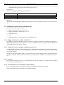
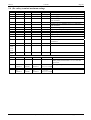
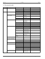
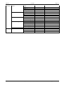
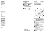
User's manual Dosing- Controller DC 155 Manual DC155_v2.0.16.doc Page 2 1 safety guidelines DC155 Table of Contents 1 OPERATION INSTRUCTION FOR EXPLOSION PROTECTED CONTROL PANELS ................................... 3 2 INTRODUCTION: DOSING - CONTROLLER DC155 ........................................................................................... 4 2.1 Short description .......................................................................................................................................................... 4 2.2 Basics ........................................................................................................................................................................... 5 2.2.1 2.2.2 2.3 2.3.1 2.3.2 2.3.3 2.3.4 2.3.5 2.4 2.5 2.6 2.6.1 2.6.2 2.7 2.7.1 2.7.2 2.8 2.8.1 2.8.2 2.8.3 2.9 Units for preset, sum counter and flow ........................................................................................................................................5 Impulse value, analogous input scaling........................................................................................................................................5 Dosing applications ...................................................................................................................................................... 5 Dosing control using digital solenoid valves................................................................................................................................5 Dosing control with proportional (analogous) valve....................................................................................................................7 Simultaneously Flow and batch control (Option) ........................................................................................................................9 Batch control with absolute level signal (requires 4.. 20mA analogous input option ) ................................................................9 Forward - backward Impulse counter (requires 2 Impulse inputs option)...................................................................................9 Creep suppression ........................................................................................................................................................ 9 Temperature compensation (requires Pt100- option) ............................................................................................... 10 Process monitoring..................................................................................................................................................... 10 Broken wire monitoring .............................................................................................................................................................10 Flow monitoring.........................................................................................................................................................................11 Safety.......................................................................................................................................................................... 11 Code words ................................................................................................................................................................................12 Key locking................................................................................................................................................................................12 Remote control / bus coupling.................................................................................................................................... 12 Remote control via digital inputs ...............................................................................................................................................12 TTY- interface and protocol print (Option) ...............................................................................................................................12 Modbus (Option)........................................................................................................................................................................13 Calibrated version, batch result print out ................................................................................................................... 14 2.9.1 2.9.2 2.9.3 2.9.4 2.9.5 Supply and interface module VI156.X.1.X................................................................................................................................14 Calibrated sensor, setting for redundant sensor wire..................................................................................................................14 Actor(s) ......................................................................................................................................................................................14 Central printer for several batch control stations .......................................................................................................................14 Additional Settings on DC155 ...................................................................................................................................................15 2.10 Scale signal amplifier connection............................................................................................................................... 16 2.10.1 2.10.2 2.10.3 Connection WV157....................................................................................................................................................................16 Scale menu / manual settings .....................................................................................................................................................16 Scale calibration.........................................................................................................................................................................17 3 INSTALLATION AND CONNECTION ................................................................................................................... 18 3.1 Mounting .................................................................................................................................................................... 18 3.2 Wiring ........................................................................................................................................................................ 18 3.2.1 3.2.2 3.2.3 3.2.4 3.2.5 3.3 3.3.1 3.3.2 Terminal description DC155......................................................................................................................................................19 Power supply..............................................................................................................................................................................19 Sensor terminals.........................................................................................................................................................................20 Actor terminals...........................................................................................................................................................................21 TTY- interface ...........................................................................................................................................................................21 Power supply of DC155 ............................................................................................................................................. 22 Application inside hazardous area..............................................................................................................................................22 DC155 for safe area application.................................................................................................................................................22 3.4 Starting, parameter default settings ............................................................................................................................ 22 3.5 Reset........................................................................................................................................................................... 23 4 OPERATION MANUAL............................................................................................................................................. 23 4.1 LC-Display ................................................................................................................................................................. 23 4.2 Keyboard .................................................................................................................................................................... 24 4.3 Parameter input and Configuration ............................................................................................................................ 25 4.3.1 Input assistance: blinking menu items........................................................................................................................................25 4.4 Dosing control flow chart........................................................................................................................................... 25 5 ANNEX ......................................................................................................................................................................... 27 5.1 Block diagram DC155................................................................................................................................................ 27 5.2 Technical Details........................................................................................................................................................ 28 5.3 Type code ................................................................................................................................................................... 28 5.4 (Ex- safety) terminal maximum ratings...................................................................................................................... 29 5.5 Documentation table................................................................................................................................................... 30 Gönnheimer Elektronic GmbH phone.: +49 (6321) 49919-0, fax: -41 Email: [email protected] DC155 1 safety guidelines Page 3 1 Operation instruction for Explosion protected control panels Application and Standards This instruction manual applies to explosion protected control panels of type of protection types below. This apparatus is only to be used as defined and meets requirements of EN 60 079 particularly EN60 079-14 "electrical apparatus for potentiality explosive atmospheres". It can be used in hazardous locations which are hazardous due to gases and vapours according to the explosion group and temperature class as stipulated on the type label. When installing and operating the explosion protected distribution and control panels the respective nationally valid regulations and requirements are to be observed. General Instructions The control panel has to have a back-up fuse as stipulated. The mains connection must have a sufficient short circuit current to ensure safe breaking of the fuse. To achieve an impeccable and safety device operation, please take care for adept transportation, storage and mounting, as well as accurate service and maintenance. Operation of this device should only be implemented by authorised persons and in strict accordance with local safety standards. The electrical data on the type label and if applicable, the "special conditions" of the test certificate PTB 98 ATEX 2071 are to be observed. For outdoor installation it is recommended to protect the explosion protected distribution and control panel against direct climatic influence, e.g. with a protective roof. The maximum ambient temperature is 40°C, if not stipulated otherwise. Intrinsically Safe Circuits Erection instructions in the testing certificates of intrinsically safe apparatus are to be observed. The electrical safety values stipulated on the type label must not be exceeded in the intrinsically safe circuit. When interconnecting intrinsically safe circuits it is to be tested, whether a voltage and/or current addition occurs. The intrinsic safety of interconnected circuits is to be ensured. (EN 60079-14, section 12) , Safety Measures: to read and to comply Work on electrical installations and apparatus in operation is generally forbidden in hazardous locations, with the exception of intrinsically safe circuits. In special cases work can be done on non-intrinsically safe circuits, on the condition that during the duration of such work no explosive atmosphere exists. Only explosion protected certified measuring instruments may be used to ensure that the apparatus is voltage-free. Grounding and short circuiting may only be carried out, if there is no explosion hazard at the grounding or short circuit connection. , Safety aspects A batch control system built exclusively with the DC155 represents a control system in category 1 according EN954-1. If a higher safety is required, it is necessary to install independent working safety facilities. ! Gönnheimer Elektronic GmbH phone.: +49 (6321) 49919-0, fax: -41 Email: [email protected] Page 4 2 Introduction DC155 DC155 2 Introduction: Dosing - controllerDC155 The following chapter 2 shows the whole functionality of the DC155, sorted by subject. Important hints for mounting, installation and starting are introduced in chapter 3. A short intro for structuring and parameter input of the DC155, as well as the complete functionality of the front keys and the display can be found in chapter 4. 2.1 Short description The dosing controller DC155 is an all purpose dosing control device to manage batch controlling of any arbitrary liquids or solid products inside the hazardous area. Advantages of this device are: • simply handling, an orderly key pad containing big (22 x 22 mm) keys, • a large graphic display and a • flexible wide functionality. The DC155 can manage simple as well as complex dosing applications inside hazardous area, without a extensive wiring to a DCS. See advantages below: Several Input sources It is possible to connect any common transmitter: NAMUR or 24V digital inputs are the standard input terminals, 4 up to 20 mA input as an option. γ -factor Temperature compensation The additional Pt100- input terminal allows a temperature compensation, if the space expansion factor γ of the dosing product is known and not neglectible. Intelligent dosing fea- The intelligent dosing program of the DC155 prevents shocks on the pipe system using a continuos raise and fall ramp by the 4 up to 20 mA – proportures tional valve output, as well as using a pair of fine and coarse valve. Intelligent batch monitoring Furthermore the DC155 includes a trouble alarm system to report flow disturbances or sensor failures. Obviously, the flow monitoring can be delayed to prevent wrong alarm during the start and finish period of the batch. Simply remote control The DC155 has several digital control inputs to realise a simple remote control with the basic functions like “START, STOP and RESET”. Powerful analogous output The analogous output can manage a load of 600 Ω directly. The optional separate supply extend the load up to 1000 Ω. PID-controlled Dosing process Some applications need a regulation of the flow during the batch process. The option “regulated analogous output” can manage this applications with an internal PID- controller. Data safety The data is stored on an onboard EEPROM, if the power supply fails. The DC155 continues at the restored state, when the mains is back. Gönnheimer Elektronic GmbH phone.: +49 (6321) 49919-0, fax: -41 Email: [email protected] DC155 2 Dosing controller DC155 Page 5 2.2 Basics 2.2.1 Units for preset, sum counter and flow The first step to configure the DC155 is to define the physical unit for preset, sum counter and flow. Therefore sufficient unit symbols are implemented into the DC155 (e.g. gram (g), kilogram (kg), tons (t), liter (l) etc.) To define the flow several time units are available. 2.2.2 Impulse value, analogous input scaling The DC155 get its information about the present flow via impulse or an analogous signal from a flow sensor. If it is a impulse signal, you have to define the value of one impulse to get the right amount of flow. If the sensor signal is an analogous signal, you have to define the maximum flow (e.g. 1000 kg/min) for 20 mA. The Impulse value and analogous input scaling is located in the structure menu in the input category. 2.3 Dosing applications Generally, a batch control system content a flow measuring, one or two valves and the batch controller. The flow sensor measures the quantity of the product per time, which flows into the target bowl and sends this information to the batch controller. The controller receive the flow information, integrates the flow signal to a sum, compares the sum continuously with the preset and controls the connected actors, which themselves controls the flow into the target bowl. The DC155 supports many sensor signals: 24V active/passive, NAMUR, 4 ..20 mA (analogous current signal) and several actors. The following application examples are sorted by the kind of actors: 2.3.1 Dosing control using digital solenoid valves The most common dosing application is the batch control using a coarse and fine valve. When the batch process is starting both valves open – a big flow of the product starts to flow. Before the preset is reached (at preset minus preset 2) the coarse valve shuts and the remain quantity will be added very exactly. Additional it is possible to configure a opening delay of the coarse valve (preset 1) and a lag quantity to take care of the pipe system and to get the exact desired quantity. See the following time diagram to understand the function of these. Gönnheimer Elektronic GmbH phone.: +49 (6321) 49919-0, fax: -41 Email: [email protected] Page 6 2 Introduction DC155 DC155 Beside it is possible to define a maximum preset, to allow only equal or smaller presets to be set. The DC155 has three free programmable digital outputs. In the example above two of them must be reserved for valve control. The following figure shows any possible function of a digital output. Select the function of digital output 1: 0. No function 1. Counter = 0 2. Fine valve 3. Wide valve 4. Dosing is running 5. Any failure 6. Flow too small 7. Flow too big 8. Impulses . End Figure 1 Digital output functions Gönnheimer Elektronic GmbH phone.: +49 (6321) 49919-0, fax: -41 Email: [email protected] DC155 2 Dosing controller DC155 Page 7 Function Description (definition: output in normal open connection) 1. Counter = 0 The digital output is closed, if the actual value is equal to zero. Otherwise the digital is the digital output open. 2. Fine valve control output for a valve with a fine cross section in normal closed connection. Also the control output for a single valve. 3. Wide valve control output for a valve with a wide cross section in normal closed connection 4. Dosing is running The output is closed, as long the preset valve is not reached and the pause time is not expired. Otherwise the digital is the output open. See also the time diagram above. 5. Any failure The output is closed, as long any disturbance (broken wire, flow to big, etc) is occurring to the DC155 or failure is no more present, but not acknowledged. Otherwise the digital is the digital output open. 6. Flow to small The output is closed, as long the flow rate is too small or this failure is not acknowledged. Otherwise the digital is the digital output open. 7. Flow too big The output is closed, as long the flow rate is too big or this failure is not acknowledged. Otherwise the digital is the digital output open. 8. Impulses Flow proportional signal: the output gives one pulse for any increase of the actual value. Table 1:function list of digital output The total quantity of various batch processes is stored by an additional sum counter. The sum counter is shown permanently at the bottom of the display. Obviously, the sum counter gets no reset after each batch. So, it provides information about the dosed product for several batches or over a longer period of time. Furthermore it is possible to realise a very simple batch control using only one digital solenoid valve. In this case you have to configure the single valve as a fine valve. Consider, the parameters like preset 1 and preset 2 (but not lag quantity !) lose their functions. 2.3.2 Dosing control with proportional (analogous) valve The DC155 can content a 4 ..20 mA analogous output to control a proportional solenoid valve as an option. The batch control parameters as shown above have by this actor version the same function. Consider the following diagram for details. You can configure the analogous output to a 0 ..20 mA or to a 4 ..20 mA signal. To get the functionality as shown in the diagram just configure the analogous output to “ Ramp shape”. It is possible to adjust the shape of the ramp. The parameter category shows at the menu item 'analogous output' the parameter 'Limit for analogous output' for limiting the maximum shape of the ramp as well as the ‘start value of the rising ramp’ and the 'End value of the falling ramp' to adjust the end value of the falling shape to 0% up to 100 %. Gönnheimer Elektronic GmbH phone.: +49 (6321) 49919-0, fax: -41 Email: [email protected] Page 8 2 Introduction DC155 DC155 Preset Actual value 100 % Proportionalvalve End value of the falling ramp Start value of the rising ramp 0% On Report: batch process is running Off time Start Stop Preset1 Pause time expired Lag quantity Start Preset 2 Preset You can configure the analogous output to a 0 ..20 mA or to a 4 ..20 mA signal. To get the functionality as shown in the diagram just configure the analogous output to “ Ramp shape”. Any alternative functions for the analogous output are shown below: Select the function of the analogous put: out- 0. No function 1. Flow prop. signal 2. Ramp shape 3. Flow feedback control 4. Counter p. sig. 5. Counter (max) p. sig. . End Figure 2 Functions of the analogous output Gönnheimer Elektronic GmbH phone.: +49 (6321) 49919-0, fax: -41 Email: [email protected] DC155 2 Dosing controller DC155 Page 9 Function Description (definition: output in normal open connection) 1. Flow prop. signal The analogous output is proportional to the actual flow 0/3 mA = 0 l/s; 20 mA = max. flow. Define max flow in the input menu The analogous output deals with a proportional working solenoid valve. See working diagram above The analogous output deals with a proportional working solenoid valve and flow rate control The analogous output shows the actual batch amount (0/4 mA = 0%; 20 mA = 100%) The analogous output shows the actual batch amount (0/4 mA = 0%; 20 mA = max. setpoint) 2. Ramp shape 3. Flow feedback control 4. Flow prop. Signal 5. Counter (max) p. sig. 2.3.3 Simultaneously Flow and batch control (Option) The DC155 has an internal PID- flow controller as an option. See item 3 of figure 2 above. With this option the DC155 is a batch controller and a PID- flow controller in one device. The batch controller fills up the desired volume and the flow controller regulates the medium flow to the predefined setpoint flow during the batch process. The setpoint flow has also a ramp shape as shown above. The dynamical behaviour of the feedback flow controller can be adjusted with the common PID parameter set Kp, Ki and Kd located in the parameter category. Like the uncontrolled output, the preset 1 and preset 2 defines a ramp shape of the analogous output to limit the slew rate. Set maximum output, if required, in item "Analogous output" in the parameter menu. 2.3.4 Batch control with absolute level signal (requires 4.. 20mA analogous input option ) This kind of batch control works not with a flow signal, but with an absolute level signal. The dosing process remains the same. 2.3.5 Forward - backward Impulse counter (requires 2 Impulse inputs option) Some kinds of flow sensors (e. g. windmill-type anemometer) recognises back flows. These have two sensors. The DC155 can determinate the flow direction using the phase relation of the two sensors. Configuration and handling of the DC155 with this option is equal to any standard application. 2.4 Creep suppression In some cases, it is necessary to ignore a transductor signal bigger than 4 mA. This threshold level is called creep suppression value. The figure on the right hand shows its function. Term of the sum Adjust the creep suppression value in the structure category. measurement value creep supression value Figure 3: creep suppression Gönnheimer Elektronic GmbH phone.: +49 (6321) 49919-0, fax: -41 Email: [email protected] Page 10 2 Introduction DC155 DC155 2.5 Temperature compensation (requires Pt100- option) Any fluid has a specific expansion coefficient γ, i.e. in general, the volume of the fluid increases with its temperature. So using a volume measurement sensor for a mass dosing application, introduces an inaccuracy into the dosing process, if the temperature changes. This inaccuracy is not neglectible for big γ . In this cases utilise the temperature compensation of the DC155, to compensate the expansion coefficient of the fluid. The DC155 corrects the density of the medium according the following formula: ρ = ρ [1 − γ (ϑ − ϑR )] with ρ: density, γ: expansion coefficient, ϑ: actual Medium temperature ϑR: reference temperature For this the DC155 measures the temperature of the fluid via the Pt100 input. Further requirement are the expansion coefficient of the fluid and the reference temperature. See the category below: Settings for temperature compensation 0. Temperature compensation: active 1. Reference temperature: 20°C 2. Coeff. of expansion:: 0.00 E-3 1/K . End 2.6 Process monitoring A batch process can be interrupted by several disturbances and errors. Even if a dosing error is inevitable, it is preferable that in any case an alarm indicates the cause. Please consider beside the following monitoring features description the batch process flow chart in chapter 4.4. 2.6.1 Broken wire monitoring The analogous 4 ..20 mA signal as well as the NAMUR- signal have according to their specification a „LIVE-ZERO“- attribute, i.e. the signal quality "zero" is dissimilar to its physical zero quality. So, it is possible to a recognise rip off or a destruction of sensor wiring. If a sensor wire brakes, then the DC155 interrupts the batch process and indicates "Broken wire" on the display. It is possible to report the "Broken wire" disturbance via a any digital output. Acknowledge the disturbance status by pressing the RESET- key. A second push on the RESET- key resets the DC155 batch counter to zero. Alternative it is possible to continue the batch process by pressing the START- key. Gönnheimer Elektronic GmbH phone.: +49 (6321) 49919-0, fax: -41 Email: [email protected] DC155 2 Dosing controller DC155 Page 11 2.6.2 Flow monitoring Flow fluctuations are considerable disturbances particularly if a reactor will be filled simultaneously with several substances or the flow exceeds the flow sensor limits. The DC155 can monitor min and max flow limits. If flow exceeds limits, the DC155 interrupts the batch process after a programmed time delay and indicates the disturbance on the display. It is possible to report the disturbance via any digital output. The figure 4 shows an example of a flow at start of a batch. The delay times are as follows: ta, : General delay tb : Selective delay at F > F max tc : Selective delay at F < F min Flow FMax FMin t ta tb tc tb The general delay starts on the begin of batch – the selective delays starts in that moment the flow exceeds its limit. If the flow did not return when the delay time is over the corresponding alarm causes. Acknowledge the disturbance status by pressing the RESET- key. A further push on the RESET- key resets the DC155 batch counter to zero. Alternative it is possible to continue the batch process by pressing the START- key. 2.7 Safety Thoughtlessness and carelessness of unauthorised people are often the cause of failures of total automatic dosing systems. We took measures on the DC155 to prevent unintentional or incompetent interruptions to the dosing process. Gönnheimer Elektronic GmbH phone.: +49 (6321) 49919-0, fax: -41 Email: [email protected] Page 12 2 Introduction DC155 DC155 2.7.1 Code words The competence to enter or manipulate configuration or parameter settings are divided into 3 safety levels: 1. The lowest level is the competence to change the preset. The authorised persons, who know the code word 'preset' are able to change the preset not more. The ex works preset code word is '0001'. If this lowest safety level is not necessary, so disable the preset code word by setting it to '0000'. 2. The medium safety level is the competence to enter the parameter category. In this category it is possible to enter or to change all remaining batch parameter like preset 1, preset 2, lag quantity, pause time, flow limits, limits delay, PID-controller parameter and the internal time clock as well as to reset the sum counter. The ex works preset code word is '0002'. The parameter category pass word can not be disabled by setting it to '0000'. The medium safety level is dedicated e.g. to maintenance personal. 3. The highest safety level is the competence to enter the structure category. In this category it is possible to change the entire structure (configuration) of the DC155 (e.g. type of unities, input signal, output signal, indication, temperature compensation, flow monitoring, key blocking) as well as changing code words. The ex works preset code word is '0003'. The structure category pass word can not be disabled by setting it to '0000'. The highest safety level is dedicated e.g. to the plant engineer. 2.7.2 Key locking In some applications the DC155 works total automatically, e.g. on remote to a DCS, without any manual control. In this cases, it will be practical to block the keys of the DC155 to prevent an unauthorised intervention. The DC155 has three level of key locking as follows: 1. Any key is enabled 2. Any key is locked, except the START,STOP and RESET keys 3. Any key is locked After the configuration, the key locking is active, if the key lock signal input (terminal 15) is high. 2.8 Remote control / bus coupling The DC155 has several interfaces to realise remote control. 2.8.1 Remote control via digital inputs The DC155 has five predefined digital signal inputs (START, STOP, RESET, INHIBIT and KEY LOCK) to realise a simple remote control with passive switches or to a high level control system (e.g. DCS). The threshold of the inputs is Low- Signal < 2 V and High- Signal > 5 V Any signal inputs except the STOP input are fix predefined in normal open connection, the STOP input is predefined in normal closed connection. 2.8.2 TTY- interface and protocol print (Option) A quite more elegant kind of remote control is via a DCS and ESC -sequences. See the instruction codes in the following table Gönnheimer Elektronic GmbH phone.: +49 (6321) 49919-0, fax: -41 Email: [email protected] DC155 2 Dosing controller DC155 Instruction code Function ESC 0 Request for counter (present value) state ESC S START- instruction ESC P STOP- instruction ESC Z RESET- instruction ESC K1 Enable keys ESC K0 Lock keys ESC B PRESET Set preset (e.g. PRESET = 001000 ) ACK (hex. 06) Answer to a known instruction NAK (hex. 15) Answer to a unknown instruction Page 13 The DC155 answers with a complete batch protocol print (contents date, time, preset amount, real (finish) amount), if the protocol print is enabled (Menu/structure/TTY interface) and it gets the 'ESC Z' instruction. 2.8.3 Modbus (Option) a) Registers The modbus interface uses only "Holding Registers" to submit measurement values and commands. The registers are defined as below: Register (Hex) 40001 40002 40003 40004 40005 40006 40007 Access Data format Function Bit field R/W R/W R/W Ctrl-Flags: Bit 0: Start Dosing process Bit 1: Stop Dosing process Bit 2: Reset Counter R R R R R R R R R/W Floating point Info-Flags: Bit 8: Dosing process is started Bit 9: Dosing process is stopped Bit 10: Counter is equal to zero Bit 11: Broken wire Sensor 1 Bit 12: Broken wire Sensor 2 Bit 13: minimum flow rate alarm Bit 14: maximum flow rate alarm Bit 15 Counter overflow Preset R Floating point Actual value R Floating point Flow rate Remarks • The „Read only“ marked Bits in Register 40001 are write protected i.e. ignore these bits while writing in this register. Write using the function 16 „Preset Multiple Registers“ and write the registers 40002 and 40003 simultaneously, otherwise the DC155 would not recognise the new preset. Gönnheimer Elektronic GmbH phone.: +49 (6321) 49919-0, fax: -41 Email: [email protected] Page 14 2 Introduction DC155 DC155 • After writing a new preset into the registers 40002 and 40003, the DC155 will take the new preset at the next dosing process (not to the running dosing process). b) Functions The DC155 supports the Modbus functions below: Function number 3 6 16 Function Read Holding Registers Preset Single Register Preset Multiple Registers a) Hardware The DC155 uses Modbus RTU, 9600 Baud, supports TTY only. The parity can be set to even, odd or inactive. 2.9 Calibrated version, batch result print out The calibrated batch system contents: 1. Batch controller DC155.X.X.X.X.4.X.X 2. Supply and interface module VI156.X.1.X 3. Calibrated sensor 4. Actor 5. Calibrated printer, interface protocol according DIN 66258 2.9.1 Supply and interface module VI156.X.1.X The Supply and interface module VI156.X.1.X is an Ex- interface module with 3 digital working inputs, 2 digital working outputs and serial interface. It works in hazardous area zone 1 with the DC155. Besides the VI156 feeds the DC155 with Ex i- Energy. 2.9.2 Calibrated sensor, setting for redundant sensor wire A calibrated batch process needs a calibrated sensor. If this sensor has terminals for 2 pulse outputs signals, so connect both to the DC155. Please configure the redundant sensor input in the Input menu of the DC155 for accurate working. The DC155 will show “Sensor failure !” if the wiring is not ok. After fixing the error quit the failure message by pressing the “RESET” button on the front. A second press the “RESET” will restart the batch process. 2.9.3 Actor(s) The VI156 has 2 internal Ex i to Ex e- relay terminals. So user can connect Ex e- actors like motors, pumps or valves direct in hazardous area. 2.9.4 Central printer for several batch control stations Use a “Auto data switcher” in safe area to connect several batch controller to one printer. Enter a individual header in each DC155 to separate the prints. Gönnheimer Elektronic GmbH phone.: +49 (6321) 49919-0, fax: -41 Email: [email protected] DC155 2 Dosing controller DC155 Page 15 2.9.5 Additional Settings on DC155 a) Menu blocking of the calibrated DC155 The menu of the DC155 must be protected against unauthorised manipulation especially by calibrated process. For this reason there must be a cable bridge inside of the DC155 to enter the menu of the DC155. To enter structure menu must the correct code word be entered and put a wire bridge between terminal 3 and 16 b) Print out For a calibrated batch process the batch data must printed out. For this enable “Print protocol” iun the Configuration of the DC155. The print out shows: [Infotext] [Date] [Time] [Set-point] [Actual Value] c) Info text With the info text field you can set a individual text on the print out. The text length is 20 characters at maximum. The text can be entered in menu “TTY- interface”, choosing “info text”. A list with all available characters are shown. Select a character with the arrow buttons and put it into text with the enter button. Delete wrong characters with “<” and confirm the info text with . Input the infotext: ABCDEFGHIJKLMNOPQRSTUVWXYZ0123456789. > Batch position 1 Gönnheimer Elektronic GmbH phone.: +49 (6321) 49919-0, fax: -41 Email: [email protected] Page 16 2 Introduction DC155 DC155 2.10 Scale signal amplifier connection The combination of the dosing controller DC155 and the scale signal amplifier WV157 is a dosing system which works with a scale signal in hazardous area. The personnel starts the batch per „start“ key on the DC155. The growing weight of the good is recognised by a scale (working with a strain gauge). When the preselected weight is reached the DC155 stops the filling process automatically. The DC155 works with a decreasing weight signal too. The scale signal amplifier is used to transform the weight signal. The small difference signal of the strain gauge will be amplified, transformed to digital and sent to the Dosing controller. Correct mounting of the WV157 in hazardous area is close to the scale to reduce disturbances. The even more disturbance safe digital output signal can be transmitted via a longer distance to the DC155 in hazardous area. For further information see manual WV157. 2.10.1 Connection WV157 Connect the WV157 to terminal 27 to 29 Figure 4 Connection of WV157 2.10.2 Scale menu / manual settings The scale menu contents all settings of the load cell and the scale amplifier. A calibration procedure can complete parameters, if some parameter are unknown. Settings for dosing with balance 0. Weight rises while dosing 1. Measuring range 2. Zero cal. 3. Tare : Auto 4. Koeff. cal. : Ja 5. 6. 7. 8. 9. Max. load cell : 10kg Gain of WV157 : 1d/mV Balance signal : 0.200mV/V Balance signal is : positive End Function Description 0. Weight rises while dosing The weight will rise while batch procedure, alternative the weight can fall while batch procedure Sets the maximum span of the scale Set the signal immediate to zero 1. Measure range 2. Zero cal. 3. Tare Gönnheimer Elektronic GmbH Automatic tare means that the scale signal is define to zero at the start moment phone.: +49 (6321) 49919-0, fax: -41 Email: [email protected] DC155 2 Dosing controller DC155 Page 17 4. Koeff. cal. Choose “Yes” If you have the parameters of the load cell shown below. If not choose “No” and make a calibration 5. Max. load cell Maximum weight of the load cell 6. Gain of WV157 Adjustment of the gain of the load cell 7. Balance signal Output signal / sensibility of the load cell 8. Balance signal is Polarity of the output signal of the load cell 2.10.3 Scale calibration Are the parameters of the scale and load cell unknown – choose “No” at “Koeff. Ca.” (item 4). The menu will change immediately to the screen below. To calibrate the scale system: load cell, scale signal amplifier WV157 and DC155 a calibrated weight is needed. First make a zero calibration (item 2) with the unloaded scale. Then enter the amount of the weight load the scale (item 5) and load the scale with the weight and choose item 6. The calibration is done. Settings for dosing with balance 0. Weight rises while dosing 1. Measuring range 2. Zero cal. 3. Tare : Auto 4. Koeff. cal. : No 5. Calibration point : 10 kg 6. Load cal. 7. End Gönnheimer Elektronic GmbH phone.: +49 (6321) 49919-0, fax: -41 Email: [email protected] Page 18 3 Installation and connection DC155 3 Installation and connection 3.1 Mounting The DC155 is dedicated for mounting and working in hazardous area zone 1. Please use the 4 holes on the rear plate for mounting and use a solid base. , NB Observe local safety guidelines and the regulative VDE DIN 57 165 See hole distances below: 260 240 110 160 Housing height: 112 mm Gehäusetiefe: 112 mm M16x1,5 Sp 5-10 M20x1,5 Sp 10-14 M16x1,5 Sp 5-10 90 130 170 Figure 5: Dimensions 3.2 Wiring , NB , Warning Please note the following Standard of Compliance: PTB 98 ATEX 2071 and the regulative VDE DIN 57 165 Do not exceed terminal safety limits of any terminal. See terminal limits on table 5.4 in the annex or the standard of compliance PTB 98 ATEX 2071 Gönnheimer Elektronic GmbH phone.: +49 (6321) 49919-0, fax: -41 Email: [email protected] 14 7 19 DC155 3 Installation and connecting Page 19 3.2.1 Terminal description DC155 Terminal 1,2 + 5,6 3+ 4+ 78+ 910 + 11,12,13,14,15,16 17+ 19+ 21+ 18202223+ 2427, 28, 29 29+ 3031 +, 32 , 33 3435+ 3637+ 38- , NB Description Power supply input Power supply input/ Option: separate power supply for analogous ouput supply output for NAMUR- Sensors Connect only to a NAMUR sensor supplied on terminal 4 Input for 24V impulses Connect only to a NAMUR sensor supplied on terminal 4 Input for 24V impulses Digital inputs (11-16: START, STOP, RESET, INHIBIT and key lock) Digital output Analogous inputs Digital interface to scale amplifier WV157 Analogous output Terminal for PT100, 4 wire connection TTY- receiver TTY- transmitter The digital input 'STOP' is a normal closed connection. For that reason please put a shorting bridge on terminal 2 to terminal 12, If you don't use the external 'STOP' See block diagram of DC155 terminals and the electrical safety limits in the annex. 3.2.2 Power supply a) Standard Gönnheimer Elektronic GmbH b) Separate power supply of analogous output phone.: +49 (6321) 49919-0, fax: -41 Email: [email protected] Page 20 3 Installation and connection DC155 3.2.3 Sensor terminals a) 24V Impulses passive b) 24V Impulses active c) NAMUR- Signal d) 4-20 mA Signal Gönnheimer Elektronic GmbH phone.: +49 (6321) 49919-0, fax: -41 Email: [email protected] DC155 3 Installation and connecting Page 21 e) Pt100 terminal (4-wire connection) (NB: a Pt100 3-wire connection is not possible) 3.2.4 Actor terminals a) Digital outputs b) Analogous 0/4-20 mA output 3.2.5 TTY- interface Gönnheimer Elektronic GmbH phone.: +49 (6321) 49919-0, fax: -41 Email: [email protected] Page 22 3 Installation and connection DC155 3.3 Power supply of DC155 3.3.1 Application inside hazardous area The DC155 needs an intrinsically safe power supply with the maximal values of U0 = 30 V, Ik = 160 mA. The power consumption of the DC155 depends on the kind and count of additional options. The basic power consumption of the DC155 (Type code = DC155.x.0.0.x.0.0.x) is about 300 mW. The power consumption is increased by any energy consuming option. For the total power consumption of the DC155 see the table below. Alternative to one powerful power supply you can distribute the power requisites to 2 less powerful power supplies (e.g. a transmitter power supply on your stock), if you ordered a DC155 with separate power supply of analogous output. Please see table below for details. Power request to power supply Hardware- Configuration Standard Of DC155 SG Minimal configuration U ≥ 15 V, separate feeding SG 1 (terminal 1 and 5) SG 2 (terminal 3 and 6) - - I ≥ 20 mA impedance ≥ 750 Ω DC155.x.0.0.x.0.0.x + analogous output U ≥ 15 V, U ≥ 15 V, U ≥ 15 V, DC155.x.a.0.x.0.0.x I ≥ 20 + 20 = 40 mA I ≥ 20 mA I ≥ 20 mA impedance ≥ 375 Ω impedance ≥ 750 Ω impedance ≥ 750 Ω + TTY- interface U ≥ 15 V, U ≥ 15 V, U ≥ 15 V, DC155.x.0.0.x.a.0.x I ≥ 20 + 20 = 40 mA I ≥ 20 mA I ≥ 20 mA impedance ≥ 375 Ω impedance ≥ 750 Ω impedance ≥ 750 Ω + 2. NAMUR- input U ≥ 15 V, - - DC155.x.0.1.x.0.0.x I ≥ 20 + 6 = 26 mA a = {1, 2} a = {1, 3} Example- configuration: U ≥ 15 V, U ≥ 15 V, U ≥ 15 V, DC155 + 2. NAMUR input + TTY-interface I ≥ 20 + 20 + 6 = 46 mA I ≥ 20 + 6 = 26 mA I ≥ 20 mA impedance ≥ 750 Ω DC155.0.0.1.0.3.0.x 3.3.2 DC155 for safe area application If you use the DC155 for safe area application and no wire of the DC155 lead into hazardous area, then you can supply the DC155 direct from a 24V DC net. It is no power supply device necessary. 3.4 Starting, parameter default settings The following table shows the parameter settings defaults. These basic defaults exist on each DC155. The parameter count can increase by any additional option. 1. category 2. category Parameter Language German, English, French, Dutch Preset: 000000. l Sum counter: 000000000. l Flow: 0000.00 l/s 24V- Input Structure Units Input Gönnheimer Elektronic GmbH Value Comment phone.: +49 (6321) 49919-0, fax: -41 Email: [email protected] DC155 3 Installation and connecting output Impulse value Max. flow 1.00000 l 10.00 l/s Dig. output 1 Dig. output 2 Dig. output 3 No function No function No function Dig. output 1 Dig. output 2 Dig. output 3 Flow monitoring Display Parameter Key locking Presets Pause time date time Codes normal closed normal closed normal closed Inactive Upper display Preset lower display Actual value Key enabled Preset 000000. l preset 1 000000. l preset 2 000000. l lag quantity 000000. l Maximum preset 999999. l Pause time 0s 07.01.1996 0:00 Preset 0001 Parameter 0002 Structure 0003 Page 23 Alternative Normal open Any key is active 3.5 Reset , Reset Reset the DC155 to its ex work configuration as follows: press the 'RESET' key while you're switching on the power supply to the DC155. After a reset the display shows: THE DC155 was reseted, all parameters are cleared, It is necessary to reconfigurate the DC155 !!! Press any key ... 4 Operation manual The user has a total control of the DC155 by the use of the front keys respectively a restricted control via a suitable remote control. 4.1 LC-Display The graphical display of the DC155 contents 2 big variable text fields and further text and graphic elements, which appear when the configuration is done. On the display any important process data is visible. Gönnheimer Elektronic GmbH phone.: +49 (6321) 49919-0, fax: -41 Email: [email protected] Page 24 4 manual DC155 4.2 Keyboard The DC155 contents 14 keys and a STOP- switch, for complete configuration, parameter changing and manual operation. The functions of any key are listed below. Key Name State STOPSwitch 1. During dosing process Valves are closed immediately, dosing process is interrupted 2. Else START- key RESET- key Function None 1. Dosing process stopped / ready Dosing process continues / starts, valves are opened 2. While menu input Cursor shift left 1. Dosing process finished / stopped Resets actual value 2. During power on proc- Activates configuration reset, any parameter ess DC155 is set to ex works values SET- key INFO- key 3. While menu input Cursor shift right 1. In operation Sets the preset value 2. Else None 1. In operation Toggle between High-level status view of the dosing process and direct input/output view 2. While menu input ENTER- key 1. In operation 2. While menu input Figure keys Gönnheimer Elektronic GmbH 1. In operation The figure '0' Starts structure and parameter menu (Code word is necessary) Confirms input / return to upper category No function phone.: +49 (6321) 49919-0, fax: -41 Email: [email protected] DC155 4 manual Page 25 2. While running menu Select menu item X 3. While figure input Choosing the figure X 4.3 Parameter input and Configuration It is not necessary to read the following section, if you want to go ahead quickly. The configuration of the DC155 is divided into 3 categories. This structure is shown in chapter 3.4. This table is mentioned as a survey. See Chapter 2 for details. , N.B. If you start the parameter or the structure menu category while a batch process is running, so the batch process will be broke immediately: the valves close, the actual value is reset to '0'. Press the ENTER- key to start parameter input. The ex works code word is '0003'. Confirm the code word input with the ENTER- key to enter main menu: Main menu 0. Language 1 .Structure 2. Parameter 3. Codes 4. Reset sum counter . End 4.3.1 Input assistance: blinking menu items The first menu item (Language) blinks on the display (grey scale). The blinking of menu items means a input assistance sequence. If the user always edit the blinking menu item, then he can be sure that 1. he won't forget or disregard any menu item, and 2. he configures the DC155 logical correct and efficient. In any case it is possible to edit a non blinking category, e.g. just to change one configuration item. Press the 'ENTER'- key to return from any menu category. The configuration is finished , if the 'End'- menu item blinks. Please press the 'ENTER'-key to return to dosing operation, with a new configuration. 4.4 Dosing control flow chart The following flow chart shows the idle loop of the dosing control. Consider that pressing the 'ENTER'key and entering the right code word will terminate this procedure in any state. After returning to dosing operation the procedure starts on the start position. Gönnheimer Elektronic GmbH phone.: +49 (6321) 49919-0, fax: -41 Email: [email protected] Page 26 Gönnheimer Elektronic GmbH 4 manual phone.: +49 (6321) 49919-0, fax: -41 DC155 Email: [email protected] DC155 5 Annex Page 27 5 Annex 5.1 Block diagram DC155 Figure 6 block diagram DC155 Gönnheimer Elektronic GmbH phone.: +49 (6321) 49919-0, fax: -41 Email: [email protected] Page 28 5 Annex DC155 5.2 Technical Details Dosing controller DC155 General Mounting Housing Electrical Specifications Inputs Outputs Power supply Ergonomy Mounting Ex-protection Housing protection class Ambient temperature Dimensions Material Main voltage Power consumption NAMUR 24V- Digital input Analogous input Measuring error Temperature coefficient Digital output analogous output minimum DC155.x.0.0.x.0.0.x Additional analogous output Add.. TTY-interface Add.. 2. NAMUR- input Display Entering configuration TTY-interface Modus DP Inside hazardous area E Ex ib IIC T6 IP65 -10°C ...+45°C at T6 -10°C ...+65°C at T4 H x B x T: 160 mm x 260 mm x 112 mm Aluminium lacquered / front foil: polyester Intrinsically safety E Ex ib IIC min.20 mA at 15V = 300 mW (without analogous output) Max input frequency: 2 kHz Threshold : 0-Signal: U < 2 V, 1- Signal: U > 5 V 4-20 mA, load: 15 Ω < 0,2 % < 0,01 % /K 3 intrinsically safe galvanically separated digital ouputs closed output remain voltage ≈ 2,5 V 4-20 mA, min 600 Ω, error < 0,2 % TK < 0,01 %/K MUS with U ≥ 15 V, I ≥ 20 mA, load ≥ 750 Ω U ≥ 15 V, current delivery see above + 20 mA or using separate MUS : DC155.x.x.x.x.x.x.1 U ≥ 15 V, current delivery see above + 20 mA U ≥ 15 V, current delivery see above + 6 mA Graphical LC-Display Menu guided languages: German, English, French, Dutch Protocol print remote control via ESC- sequence Control, operate, Indicate with Bus- Interface 5.3 Type code .x .x no analogous input ........................................................ .0 One 4...20mA analogous input......................................... .1 Analogous output no analogous output................................................................. .0 One 4...20mA analogous output ............................................. .1 PID controlled analogous output............................................ .2 NAMUR- input NAMUR- input..................................................................... .0 two NAMUR- inputs................................................................. .1 Pt100- input: no Pt100- input................................................................................. .0 One Pt100- input................................................................................... .1 TTY- interface: no interface..................................................................................................... .0 TTY- transceiver............................................................................................. .1 TTY- transceiver and receiver ....................................................................... .2 TTY- receiver ................................................................................................. .3 Modbusno bus PA interface............................................................................... .0 Interface with Modbus DP interface.................................................................................. .1 Separate power supply no separate power supply......................................................................................... For analogous output with separate power supply........................................................................................... DC155 .x .x .x .x .x .0 .1 Analogous input Gönnheimer Elektronic GmbH phone.: +49 (6321) 49919-0, fax: -41 Email: [email protected] DC155 5 Annex Page 29 5.4 (Ex- safety) terminal maximum ratings Inputs terminal voltage current Power Ci, Li 30V 160mA 2,5W 2nF, 5µH 1, 2 30V 160mA 2,5W 2nF, 5µH 3 7 8 9 60V 160mA 5µH 10 11 ... 16 17, 18 19, 20 21, 22 23, 25, 27 32, 33 60V 60V 30V 30V 30V 30V 160mA 160mA 160mA 160mA 160mA 160mA 5µH 5µH 5µH 5µH 5µH 5µH 1,5W 1,5W 1,5W Comment power supply for DC155 power supply for DC155or analogous output Connect only to a NAMUR sensor in combination with terminal 4 Input for voltage impulses Connect only to a NAMUR sensor in combination with terminal 4 Input for voltage impulses Digital inputs, Impedance per input min. 25 kΩ Digital output Digital output Digital output Analogous input Connect only to a Pt100 sensor in combination with terminal 31 5µH TTY- Receiver 5µH Masse 35 60V 160mA 1,25W 5, 6, 24, 26, 28, 30, 34, 36, 38 39, 40, 16V 160mA 5µH Not used 41, 42 Outputs terminal voltage current Power Ca, La Comment 4 9,4V 21mA 3,8µF, 30mH Power supply for MANUR sensors. The maximum power (with terminal 7 or 9 ) is 234 mW per sensor Analogous output 29 -12nF C aSpeisekreis see see see -10µH L aSpeisekreis terminal 1 terminal 1 terminal 1 31 5,4V 6mA 8mW Connect only to a Pt100 sensor 37 CaSpeisekreis-12nF TTY-Transceiver see see see LaSpeisekreis-10µH terminal 1 terminal 1 terminal 1 Gönnheimer Elektronic GmbH phone.: +49 (6321) 49919-0, fax: -41 Email: [email protected] Page 30 5 Annex DC155 5.5 Documentation table 1.Category 2. Category language Structure Units Parameter value / choice German English French Dutch preset sum counter flow 000000 000000000 000000 active inactive decreases increases Batch control with absolute level signal Input Output level during batch process level bei 4 mA level bei 20 mA Type Impulse value 4 mA correspond to 20 mA correspond to Max. flow Dig. output 1 Dig. output 2 Dig. output 3 Dig. output 1 Dig. output 2 Dig. output 3 Analogous output function Analogous output function Flow monitoring Temperature compensation Display TTY- interface Key blocking Gönnheimer Elektronic GmbH reference temperature expansion coefficient upper Display lower display Baud rate Bits Parity print protocol Eichfähiger Betrieb Swap float Modbus adress Comment 24V- Input NAMUR 4-20 mA normal open normal closed normal open normal closed normal open normal closed 0-20 mA 4-20 mA active | inactive active | inactive °C /K (calibration only) (calibration only) (Modbus only) (Modbus only) inactive partial active total blocked phone.: +49 (6321) 49919-0, fax: -41 Email: [email protected] DC155 Parameter 5 Annex Presets PID controller Analogous output Flow monitoring Pause time Codes Gönnheimer Elektronic GmbH Page 31 preset preset 1 preset 2 lag quantity Max. preset desired flow rate Kp Ki Kd Maximum value Start value rising ramp End value falling ramp min. flow max. flow delay flow monitoring delay for Q<Qmin delay for Q>Qmax pause time Preset Parameter Structure phone.: +49 (6321) 49919-0, fax: -41 Email: [email protected] EG-Konformitätserklärung Declaration of conformity / Déclaration de conformité Communauté Européenne Anbieter: Supplier: Fournisseur: Gönnheimer Elektronic GmbH Anschrift: Address: Adresse: Gewerbegebiet Nachtweide Dr.-Julius-Leber-Straße 2 67433 Neustadt/Weinstraße Produkt: Product: Produit: DC155, Dosiercontroller Das oben beschriebene Produkt erfüllt die Schutzanforderungen der folgenden EG-Richtlinien / the product described above complies with the following EG- rules / le produit décrit cidessus accomplit CU- réglementations 89/336/EWG, 93/68/EWG, 94/9/EG und ist konform mit / and is in conformity with / et est conforme á: EN 50014: 1997, Allgemeine Bestimmungen EN 50020: 1994, Eigensicherheit „i“ EN 61000-6-3: Fachgrundnorm Störaussendung; Teil 6-3: Wohnbereich, Geschäfts- und Gewerbebereiche sowie Kleinbetriebe EN 61000-6-2: Fachgrundnorm Störfestigkeit; Teil 6-2: Industriebereich DIN VDE 0106-100:1983, Schutz gegen elektrischen Schlag zusätzliche Angaben / additional information / informations supplémentaires: Qualitätsmanagement- System nach ISO EN DIN 9001 Anerkanntes Qualitätssicherungssystem nach Richtlinie 94/9/EG EG- Baumusterprüfbescheinigung / EC- Type certification / Attestation d’examen ce de type PTB 98 ATEX 2071 Gönnheimer Elektronic GmbH rev.1 CE-Konformitätserklärung_serie_sertig.doc