Transcript
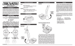
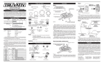
www.truvativ.com Hussefelt Chainguide - 2001 Installation and Service This manual will cover the installation of the TruVativ Hussefelt crank arms and Chain Guide. To ensure correct installation and performance we recommend the services of a qualified, professional bicycle technician. If you are adventurous and plan to install these parts yourself, please read this entire manual carefully before proceeding. TruVativ assumes no responsibility for malfunction or injury caused by faulty installation or maintenance. And you should be aware that bolts can rattle loose and parts may be damaged after a crash. All parts must be frequently checked and serviced to ensure safety. Parts & Tools Parts: Tools: Guide arm Spline Interface Torque: 43-48 N-m 32-35 ft-lbf 421-470 kgf-cm Pedal assembly Torque: 31-34 N-m 23-25 ft-lbf 316-347 kgf-cm A B Note: Use E-Type BB with 113mm spindle Chain Guide Installation The chain guide fits between the drive side bottom bracket cup and the frame as shown below. Follow torque requirements specified by the BB manufacturer. The TruVativ logo should face away from the bicycle frame. Frame Bottom Bracket Shell Apply threadlock compound here Fixture plate Fixture t-nut connected to fixture bolt Square-hole Interface Torque: 38-42 N-m 28-31 ft-lbf 372-411 kgf-cm Left Crank 5, 6 & 8mm Allen keys Torque wrench Flat blade screwdriver Pulley Bushing Bolt Attention drivetrain side right hand pedal-thread Use and 8mm Allen wrench Figure 2. Rear Views of Drive Side Figure 1. Identifies the parts of the chain guide. Install the crank assembly as specified in Figure 4. Grease the bottom bracket capless bolt threads and under the bolt head, then tightened to the torque requirements in Figure 4. It is important to remember that if bolts are not tight, they may come loose. If too much torque is applied, then the bolt may fail. It is necessary to use a torque wrench for proper installation. Pedal Hussefelt Crank Arm, Right Hussefelt Crank Arm, Left Chain Guide Chain Guide Overview BB-set location Please Note: The guide arms can be placed on either side of the fixture plate to allow for different chainring placement. Below in Figure 2, the arms are shown in both configurations. In view A the chainring is placed on the inside of the spider and the guide arms are placed to the inside of the fixture plate. View B the chainring is placed to the outside of the spider and the guide arms are placed to the outside of the fixture plate. Figure 4. Attention non-drivetrain side left hand pedal-thread Figure 5 shows the correct placement of the guide arms and pulleys in relation to the bicycle chainstay. Pulley A is approximately located between the 11 oclock and 12 oclock position, this is the location where the chain and chainring teeth meet when the chain is in the largest cassette on the rear wheel and the suspension is fully compressed. Pulley B is located between the 7 and 8 oclock position. Both pulleys should be placed so the chain and chainring are overlapped by the flanges of the pulley. Pulley A Figure 5. Pulley B Bottom Bracket Figure 3. Finally, the fixture bolt, BB-set button head screw and pulley bushing bolts should be tightened to a torque of 6-7 ft-lbf or 8-9.5 N-m or 81.5-97 kg-cm. The setscrews on the BB-set should be tightened to a torque of 30-40 in-lbf or 3.5-4.5 N-m or 36-49 kg-cm.