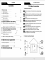
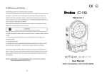
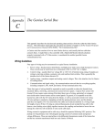
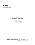
1
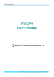
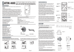
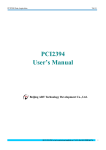
Warning
1. This product belongs to wireless transmitting equipment,
please under the approval of local Radio management
departments then use it.
2. Although this system is an advanced anti-theft system, as a
technical means of prevention can prevent, reduce theft,
robbery, fire or other things happen, but can not guarantee
no above things happen or no casualties or property
damage.
Wireless Alarm System
3. The PIR detectors can only detector the intruder in the
detecting area. The detecting area please find in the
manual. It can 't detector the object motion or intruder
behind the wall, on the ceiling, under the floor, behind a
closed door, glass wall, glass door or glass window.
4. The sensitivity of the detector may effect by the environment
and temperature. When the detecting area the temperature
is in 32℃~40℃, the detect capability (detect distance) will
bring down. The users have to check the detectors' working
performance in this kind of temperature and adjust it
suitable.
5. This product is an advance wireless warning device but just
like other electronic products, it may have false sometime.
Please test the system punctual to make sure it work stably
and reliably. If there is any unusual please contact the local
supplier in time.
.
User Manual
Contents
User manual
User manual
Contents
1: Product overview
1: Product overview
..........................................
(1)
(1)
1.1 Brief introduction ............................................
1.2 System working diagram ..................................
(1)
1.3 Control panel description..................................
1.4 Detector description ........................................
(2)
(2)
1.5 Remote control description...............................
................
2: System installation and debug
2.1 System installation, debug and precautions
(4)
(4)
(4)
...............
.............
2.2 Safety requirements of PIR detectors
3: Structural diagram description
3.1 Coding status LED description
3.2 Add/delete of the remote control
3.3 Add/delete of the detector ................................
(5)
(6)
(7)
4: Main technical parameter
.........................
1.1 Brief introduction
Detectors, remote controls and host are using learning
code.
Add Remote control to arm/disarm and emergency alarm.
20s arm delay when turn on, alarm information memory
function.
Anti- tamper alarm and low battery prompt.
High/low warning sound optional and the warning sound
will automatically stop after 5minutes.
DC 12V alarm output interface which can be used with
external equipments.
AC 220V output socket which can be used in lighting
or connect warning lights. (Maximum 440W)
Detectors and panel distance up to 300~1000M.
Use AA Battery as back up battery, when the DC power if
off, the systems can work normally.
.........................
3.4 Recover factory default setting
4.1 Control panel parameter
(4)
(5)
(5)
....................................
1.2 System working diagram
(7)
(7)
Wireless
detector
........................................
DC12V Active siren
Wireless
access
4.2 Detector parameter ............................................ (8)
5: Standard package
Product overview
(9)
Alarm
linkage
AC alarm light
Wireless
detector
Remote
control
AC searchlight
User manual
Product overview
User manual
Product overview
1.3 Control panel description
1. Volume level: High level,
alarm volume more than
90dB; Low level, alarm
volume more than 80dB;
Default level is high level
2. Power switch: 'ON' for
power on, 'OFF' for power off
3. DC output port: DC12V
linked external power output
port when alarming
A. Power-saving pattern features:
Continuous body movement won't effect
the alarm after detectors triggered and
alarmed to control panel. If the detector
first triggered and no body movement
detected over 10 seconds, alarm signal
would be sent again to control panel. In
the power
4. AC output port: AC220V
linked external power output
port when alarming(Attention:
when connect or disconnect
this port, please make sure to
B. Standard pattern features:
shut off the panel power and no naked wire in case
of electronic shock)
5. Disarm button: Alarm stop when press this button.
1. Pulse option: Insulation cap inserted in number one, it's
double pulse mode, infrared sensitivity is low; Insulation cap
plugged in number two, it's single pulse, infrared sensitivity is
high. Factory default mode is single pulse.
6. Emergency button: Immediately alarming when press this
button
7. Tamper switch: Alarming immediately once panel
1.4Detector description
Mode option: Detector have two kinds of working pattern,
Power saving mode and Standard mode. As shown in
picture, Insulation cap plugged in number 1, mode is power
saving;Plugged in number 2, mode is standard. Mode
change must be reenergized(Remove the battery, reload
after 30 seconds)
Detector first triggered and alarming up
to 5 minutes, and detector won't detect any infrared movement
during this 5 minutes. Detector will send alarm signal to
control panel again if triggered after 5 minutes or more. The
factory default mode is standard mode.
2. Sensitivity level option: Detector have 3 levels for
sensitivity, H/M/L levels. 8-12m detecting range for
'H' level, 6-8m 'M' level, 4-6m for 'L' level. Factory
default level is 'H' level.
3. Power switch: Power switch turn to 'ON', detector
works; Turn to 'OFF', detector stop working. The detector
will send alarm to panel when power on or power off.
4. Infrared sensor: Don't touch sensor surface with your hand.
If any dirt on the surface, you can clean it with 75% alcohol
cotton.
System installation and debug
User manual
User manual
Structural diagram description
3: Structural diagram description
1.5 Remote control description
1.
Arm: System start to arm
when press this button
2. Disarm: System disarm when
press this button
3.
Emergency: System immediately
alarming when press this button
2: System installation and debug
2.1 Control panel installation
1. The panel should installed in a hidden place but be attention the
loudspeaker don't have any cover to make sure the alarm
volume is normal.
2. The receiving host is not explosion-proof type, so it can't be used in Ⅰ
, Ⅱ, Ⅲ level dangerous places, which have certain concentration of
flammable gas, dust and fiber. Otherwise, danger will possibly take
place.
3. Don't put the receiving host close to strong electromagnetic
radiation equipments, such as TV set, air-conditioner, computer,
microwave and so on, so as not to affect the antenna reception.
2.2 PIR detector installation
1. When human beings move horizontally, the sensitivity of the
detector is high, when move vertically, the sensitivity is low. In
this way, please installed the detector in suitable place.
2. Be attention to the high angle of the detector and the horizontal
plane, it will have huge influence to the alarming area. Best
detector installation height is 2 meters, angle with wall is 0~15o
3. Do not put detector under direct sunshine, car head lights, etc.
Avoid to face the door and windows directly.
3.1 Coding status LED description
1.When coding, the green light off, the zone light on zone
1 2.When coding success, the zone light stop flashing and
you will hear a short “DI” sound
3.When coding failed (repeat code or restriction code), the zone
light stop flashing and you will hear a long “DI” sound
3.2 Add/Delete remote control
Coding operate(Add remote control)
1. Long time Press “emergency” button on the panel and
power on at the same time, you will hear a short “DI” sound
then release the “emergency” button, the “ZONE 1” LED on.
2. Press “disarm” button to choose defense zone from zone 1
to zone 4, then press “emergency” button to confirm
defense zone, zone led flash and press any key on the
remote controller to trigger for programming
3. After hear a short 'DI' sound, zone led stop flashing,
remote controller adding finished. If you hear a long
'DI' sound, it means repeat code or restriction code.
4.Repeat step 2, 3 to continue coding, or power off to quit.
Remarks: In same defense zone, if this zone already added
1 remote control. The first one will be deleted when added a
new remote control When enter into coding status, press
'disarm' button and confirm the defense zone, long time
press 'emergency' button. After hearing a long 'DI' sound,
remote control deleted
User manual
Structural diagram description
Remote control add/delete instructions:
Turn off the host power,long
time press “emergency”button
and powered on.
Press “disarm” to choose
the zone of coding.
Delete remote control
User manual
Main technical parameter
Detector add/delete instructions:
Press “emergency”
to confirm the zone
of coding.
Turn off the host power,long
time press “disarm”button
and powered on.
Press “disarm” to choose
the zone of coding.
Add remote control
Delete detector
Long time press “'emergency”
button. release after hearing a
long 'DI' sound.
Press “emergency”
to confirm the zone
of coding.
Press “arm” on remote
control,and send address
code.
Long time press “emergency”
button. release after hearing a
long 'DI' sound.
Add detector
Trigger detector,and send
address code.
3.3 Add/delete detector
Add detector:
1. Long time press 'disarm' button on control panel and
power on at the same time. You will hear a short “DI”
sound then release the “disarm” button, the “ZONE 1”
LED on.
2. Press 'disarm' button again, then choose defense
zone from zone 1 to zone 4, Press 'emergency ' button
to confirm defense zone, zone led flash and detector
triggered for programming
3. After hear a short 'DI' sound, zone led stop flashing,
detector adding finished. If you hear a long 'DI' sound, it
means repeat code or restriction code.
4.After detector finish adding, you can press 'emergency '
button to add the next detector in this zone. Press 'disarm'
button to choose defense zone again. Or power off to quit.
Remarks: In same defense zone, if this zone already
added 3 detectors, the first detector will be deleted
when the 4th detector added
Delete detector:When enter into coding status, press
'disarm' button and confirm the defense zone of the
detector you want to delete, long time press 'emergency'
button. After hear a long 'DI' sound, detector deleted
3.4 Recover factory default setting
Press 'emergency ' and 'disarm' button and power on at the
same time. After hear a long 'di' sound, release the buttons
and defense zone led start flashing. Long time press
'emergency “button, release after hear a long 'di' sound, all
LED on, factory default down. Power off and reopen the panel.
(When factory default, all the detectors, remote controls are
deleted)
4: Main technical parameter
4.1 Control panel parameter
1. Working voltage: AC220V±15%;DC12V (8pcs of AA
battery)
2. Operation current: Static≤15mA; Alarm≤180mA
3. AC output: AC 220V 2A (440W)
4. Alarm time: 300 seconds
5. Receiving frequency: 315MHz
6. Wireless receiving distance: 100-500m (in the open land)
7. Dimension: 212*150*40mm (including antenna)
User manual
Main technical parameter
User manual
8. Alarm output: DC 12V
9. Alarm output: AC 220V (only some models)
4.2 Detector parameter
1. Using dual infrared sensor, high sensitivity.
2. Micro-power consumption, Static Current ≤50Ua.
3. 3 grades for sensitivity adjustable.
4.Monopulse and dipulse optional.
5. Anti-white intensity ≥10000LUX.
6. Using
SAW
steady
transmitting circuit
frequency
Standard package
5:Standard package
Item
Description
Wireless alarm 1*Control panel, 2*PIR detector, 2*remotecontrl, system User manual, accessories
wireless
7.MCU intelligent digital processing. 8.Antielectromagnetic interference, low false alarm. 9.
Automatic temperature compensation 10.Standard
mode and intelligent cost-saving mode
optional
D
e
t
e
c
t
i
o
n
Detection range:4-12M(optional)
0 to 15
0
a
n
g
l
e
0
Top view
01
Side view
-9-