1
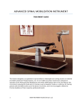
ADVANCED SPINAL MOBILIZATION INSTRUMENT
USER MANUAL
This document has been prepared to give the user an insight into safety, maintenance and general
operation of the Advanced Spinal Mobilization Instrument (ASMI). Also incorporated are guidelines on
specifications and spare parts. It is recommended that this document be read prior to initial use as well
as a reference for continuous use in order to familiarize the operator with an electro-pneumatic system
as well as guidelines on the individual operational settings and the use of the device.
1
ASMI USER MANUAL (Version 1.01)
Table of Contents
GENERAL INSTRUCTIONS AND SAFETY .......................................................................................... 3
Compressed Air Safety ......................................................................................................................... 3
Operator Safety When Using the ASMI .............................................................................................. 3
Constituents of the ASMI System ........................................................................................................ 4
Operation ................................................................................................................................................. 6
ASMI Display and Keyboard Layout................................................................................................ 6
Using the ASMI ................................................................................................................................... 7
Maintenance............................................................................................................................................ 7
Filter Maintenance .............................................................................................................................. 7
Troubleshooting .................................................................................................................................... 10
Specifications ........................................................................................................................................ 12
General Spare Parts Listing ............................................................................................................... 12
Storage and Transport Conditions..................................................................................................... 12
Compressor recommendations .......................................................................................................... 12
Warranty .................................................................................................................................................... 12
2
ASMI USER MANUAL (Version 1.01)
GENERAL INSTRUCTIONS AND SAFETY
Compressed Air Safety
Compressed air represents a source of considerable potential energy and, as with electricity,
precautions must be taken to prevent accidents.
Compressed air should never impinge upon the body. Ports and pipes etc. should never be blocked by
hand. Before connecting any pneumatic equipment to compressed air supply, mountings, fittings, pipe
work and electrical connections should be checked for security and all or any plastic plugs removed . No
pipe work alterations or removal of fittings should be attempted with air supplies connected.
Air and electrical supplies must be disconnected before any maintenance is undertaken.
The maximum allowable operating pressures, electrical supply, temperature, loads etc. should be
observed. Refer to "Technical Information" in this manual for this information and for any other
operating limits.
The guidelines outlined above, however, are for general compressed air usage. It should be noted that
the only external components of the ASMI which are compressed air sources are:
•
•
•
•
The main air supply line from the compressor to the console unit and its subsequent connection
to the ASMI. This is comprised of specialized coupling fittings, which, even when disconnected,
will not allow the escape of compressed air.
The pneumatic handset assembly incorporating four pneumatic pistons connected to the control
console by coiled tubing. This unit is completely sealed and is simply plugged (for both electrical
and air supplies) into the front face of the control console. Never press "RUN" on the control
console unless the handset is held firmly in the operator's hand. The pneumatic actuators built
into the handset will reciprocate with force.
The two-stage compressed air filter assembly. Air supply connection to and from these filter
units is provided internally by the ASMI control console. These filter units require only routine
maintenance (refer to "Filter Maintenance").
The factory-set compressed air regulator unit between the two filters. Without this regulator, air
would be supplied from the compressor at too high a pressure, resulting in damage to internal
components. The regulator is factory-set and as such will need no adjustment and is
maintenance-free. Air supply connection to and from the regulator unit is provided internally by
the ASMI.
Operator Safety When Using the ASMI
The ASMI assembly is a complete operating electro-pneumatic system. The operator should never open
or dismantle any part of the unit other than during the process of carrying out routine maintenance of
the filter elements (refer to "Filter Maintenance"). Opening or dismantling any part of the unit other
than during filter maintenance will invalidate the warranty.
3
ASMI USER MANUAL (Version 1.01)
The operator should also be aware of the following safety guidelines. Failure to follow these guidelines
will invalidate the warranty.
•
•
•
•
•
•
•
•
•
•
•
•
•
•
•
Protect your ASMI from strong impacts. Be careful not to drop it or place heavy objects on it.
Avoid applying excessive force to the controls and keys. Always unplug cables by gripping the
plug firmly and not by pulling the cable.
The ASMI should be situated away from any heat sources such as radiators. Avoid exposure to
direct sunlight or other sources of heat. Avoid highly humid or dusty places.
Due to sensitive internal electrical components, the system should never be used near water or
where a damp atmosphere or moisture is present.
Due to the reliance of the filter units on material gathering in the base of the bowls, the ASMI
unit should only be used on a level surface.
Ensure all air connections to the ASMI are secure before supplying compressed air to the
system.
Do not exceed the maximum supply pressure of the ASMI (refer to "Specifications").
Should abnormal air leakage be heard from any part of the ASMI assembly, turn the air and
electrical supply OFF at the source immediately and contact Advanced Therapy Systems.
Though not essential, it is good practice to ensure that the air supply is turned off at the source,
before removing the supply fitting.
The ASMI is supplied with highly flexible air and electrical connection lines. Nevertheless, it is
important to ensure that the tubing never kinks and that regular inspection is conducted in
order to check for deterioration of the tubing material.
All checking or servicing of filter elements (i.e., when bowls are removed from the filter units)
should be carried out while the air and electricity supply are disconnected from the ASMI.
Unplug the AC adaptor from the electrical outlet if the instrument is not to be used for long
periods of time or during electrical storms.
If an abnormal smell or smoke is detected, immediately turn air and electrical supplies OFF and
remove the main adaptor unit from of the socket. Contact Advanced Therapy Systems.
When cleaning, never use volatile solvents such as alcohol, paint thinner or benzene. Use a
clean dry cloth.
Do Not use talcum powder with or near the ASMI, as this will damage the unit.
If the ASMI unit is to be moved, it is important to ensure that the filter bowls are drained and
there is no water in the bowls. See "Filter Maintenance." Failure to drain the filter bowls before
moving the unit may saturate the filters with water and oil deposits, which will be transferred
through to the sensitive instrumentation in the equipment and lead to malfunction and failure.
Constituents of the ASMI System
In order for the ASMI to operate efficiently, clean, high quality compressed dry air is essential for longterm operation. Correct air preparation can minimize the risk of component failure and generally result
in a longer life expectancy of the pneumatic components.
4
ASMI USER MANUAL (Version 1.01)
Contaminants naturally occurring in the atmosphere such as dust, grit and pollen are compressed at the
same time as the air and, unless filtered, will be circulated throughout the system. These particles may,
in low concentrations, be no danger to the system. However, combined with forms of moisture (usually
water vapor which naturally occurs in the air), will eventually solidify and gradually accumulate on both
static and moving surfaces within the pneumatic equipment. This will cause the valves to stick, seals and
other components to wear, and ultimately lead to failure of the device. Due to the large cycles of
reciprocating actuation experienced within the handset, a two-stage filter system has been incorporated
within the ASMI and, if routinely maintained, will result in effective operation of the unit. The filtered
matter, usually in the form of moisture, will in time build up at the bottom of the two filter bowls and
should be checked after 8 hours of usage or every day and drained accordingly. Refer to "Filter
Maintenance" on how to drain the filtered matter.
The first stage Filter has an element which is capable of 5 µm filtration. This filter is intended to remove
the larger contaminants in the airline supply from the compressor. It is recommended that this filter
element be replaced on a yearly basis and should be routinely checked after 2,000 hours of use.
The second stage Filter incorporates a micro-filter cartridge element which is capable of 0.3 µm
filtration. This secondary factory-set filter is placed in line after the first filter and removes dust and oil
mist as well as supersaturated moisture. It is recommended that this element be replaced on a yearly
basis. It should be routinely checked after 2,000 hours of use.
The four electrical and air connections incorporated in the ASMI are all specific for their particular use
and are not interchangeable. Refer to Figure 3.
•
•
•
•
To connect the main air supply line to the control console, ensure the female coupling from the
compressor line is placed over the male connection (2) and pushed firmly "home" until the
coupling locks. To remove the connection, hold the socket in place and pull the collar away from
the control console.
To connect the electrical supply, insert the plug from the main adapter unit into the mating
socket (3).
When connecting the air line for the handset into the control console, place the male plug from
the handset line into the mating coupling on the front face of the console and push firmly until
the fitting locks into position. To remove the connection, push the collar towards the control
console.
To connect the electrical supply from the control console to the handset, ensure that the fourpin plug is aligned with its mating socket on the front face of the control console. Once the plug
is fitted into the socket, secure the connection by turning the lock ring supplied with the plug
clockwise until finger tight.
When all four connections have been made, the ASMI is ready for use. Turn on both air and electrical
supplies.
5
ASMI USER MANUAL (Version 1.01)
Operation
ASMI Display and Keyboard Layout
The keyboard on the control console is divided into three main sections. - Introductory, Reflex and
Mobilize.
Selection of the required mode is made by pressing the appropriate Mode change button. The Effort (or
intensity) and the Frequency for each mode can be adjusted up or down using '+' or '-' buttons (refer to
figure1). The left digit on the numeric display, below each Mode Change Button, displays the Effort level.
The right digit displays the Frequency level. The RUN and STOP buttons activate and deactivate the
Handset once a mode has been selected.
Figure 1. (Console Layout)
The Bar graph LED display gives a visual representation of the Force and Frequency settings in each
mode.
6
ASMI USER MANUAL (Version 1.01)
Using the ASMI
The AST Spinal Mobilization Instrument is the first technology-assisted instrument for the physical
therapist or other licensed medical professional to consistently and effectively perform Maitland's spinal
mobilization techniques.
Treatments alternate between the threes modes: Introductory, Reflex and Mobilization
•
•
•
Introductory Mode: After the patient has comfortably positioned him/herself on the treatment
table, initiate the Introductory mode and, with a gentle touch, run the handset along the length
of the spine. The setting lasts for 15 seconds and serves to acclimatize the patient to the touch
and feel of the handset on the back and spine.
Reflex Mode: Cradle the handset with both hands and allow it to move along the length of the
spine, stimulating the reflexes of the paraspinal muscles from the lumbosacral to the thoracocervical junction. Initiate this mode immediately after the introductory mode and periodically
during the mobilization mode.
Mobilization Mode: Begin in the sacral area at low settings and gently but firmly apply pressure
to the handset to mobilize the vertebral articulations. Slowly move up and down the spine from
the lumbosacral to the cervico-thoracic areas keeping the handset centered over the spinous
processes and allowing the pads of the handset to gently mobilize spinal segments by exerting
pressure on the transverse processes.
Maintenance
Filter Maintenance
Check every day before use or after 8 hours usage
If water has built up in either of the two Filter Bowls, please take the following steps, referring to Figure
2 below. If water in the Filter Bowls is a regular occurrence, contact Advanced Therapy Systems as there
may be an issue with the compressor.
a) Connect the main air supply to the console through its respective socket (2). This will pressurize
the system facilitating the condensate drain.
b) Press the button (C), located at the bottom of the Filter Bowl (B). Warning - When draining the
moisture from the Filter Bowl, ensure the use of a suitable container to catch expelled moisture.
NOTE: The fluid will be discharged from the bowl under pressure and suitable caution should be
taken.
c) When the moisture is fully drained and only air is being expelled from the filter unit, release the
button (C).
For best practice, briefly purge the filter bowls every working day even though there may be no visible
accumulation of moisture. This daily habit ensures the best air quality for your equipment and prevents
the accumulation of significant amounts of condensate. If conducted daily, a facial tissue is usually
sufficient to absorb the moisture that is present.
7
ASMI USER MANUAL (Version 1.01)
No
A
B
C
Description
Filter Unit
Filter Drain Bowl
White Drain Button
Figure 2. Filter Bowl
Check every year or after 2,000 hours usage.
Checking and changing the filter elements for contamination (Refer to Figure 3). Poor quality air
supplied from the compressor can cause contamination and create blockages within the filter element.
This could cause a pressure drop and affect the efficiency of the unit. When the element is very dirty, it
should be replaced. When the bowl is dirty, it should be washed using a neutral cleanser. To check and,
if necessary, replace the filter elements, the following steps should be taken:
a) Ensure that the main air pressure line and the electrical plug are disconnected from their
respective sockets (2) & (3). It is recommended that the following steps be carried out in a clean
environment to prevent any contamination.
b) Remove the preliminary Filter Bowl (8) by pushing down the black release clip (10), twist the
Drain Bowl clockwise until the vertical lines on the filter body line up with vertical lines on the
Drain Bowl, making sure the black release clip is held down.
c) Now gently pull the Bowl (8) away from Filter Body (6).
d) Remove black Baffle plate (12) by unscrewing. Caution: Ensure that Baffle plate (12), element
(13) and deflector (14) do not drop. If a replacement 5 µm element is required for stage 1, use
or request the following preliminary filter replacement part:
Replacement 5 µm filter element (13) part number: 111585A
e) Replace Deflector (14), Element (13) and Baffle (12) back onto mounting stud and screw the
Baffle to secure. Caution: Tighten by hand only.
f) Replace the Bowl (8) back into location grooves in the bottom of the filter unit (6), ensuring the
vertical lines line up. Twist the Bowl until the black release lever (10) locks, indicating that the
catch has been made and that the Bowl is secured once again to the Filter Body.
8
ASMI USER MANUAL (Version 1.01)
g) Remove the secondary filter Bowl (9) by pushing down the black release clip (11), twist the drain
Bowl (9) clockwise until the vertical lines on the Filter Body line up with vertical lines on the
drain bowl, making sure the black release clip is held down.
h) Now gently pull the Bowl (9) away from Filter Body (7).
i) Remove the micro filter element by unscrewing from the mounting stud. If a replacement O.31
µm element is required for stage 2, use or request the following micro filter replacement part:
Replacement O.31-lm micro Filter element (15) part number: 630617
j) Secure the Element (15) back onto mounting stud by turning counter-clockwise. Caution:
Tighten by hand only.
k) Replace the Bowl (9) back into location grooves in the bottom of the filter unit (7). Ensure the
vertical lines line up, twist the Bowl until the black release lever (11) locks, indicating that the
catch has been made and that the Bowl is secured once again to the filter body.
l) Re-connect the air and electrical supplies to the relevant socket (2) & (3) on the control console.
The ASMI is now ready for use again.
Should there be an air leakage from either of the filter units, disconnect the electrical and air supplies
before checking the seating between the bowl and the main filter unit housing. If the problem persists,
contact Advanced Therapy Systems.
Rear view on control console
9
ASMI USER MANUAL (Version 1.01)
No.
1
2
3
4
5
6
7
8
Description
ASMI Control Console
Mains Air in Connection Fitting
Electrical In Connection Socket
Fuse Holder Socket
Factory Set Regulator Unit
Stage 1 (Preliminary) Filter
Stage 2 (Secondary) Micro Filter
Stage 1 Filter Bowl
Spares PT No.
not available
not available
not available
not available
not available
not available
not available
C300F
No.
9
10
11
12
13
14
15
-
Description
Stage 2 Filter Bowl
Stage 1 Bowl Release Clip
Stage 2 Bowl Release Clip
Black Baffle Plate
Stage 1 (5µm) Filter Element
Deflector Plate
Stage 2 (0.3µm) Filter Element
1A Fuse
Spares PT No.
C300F
not available
not available
not available
111585A
not available
630617
415-569
Troubleshooting
a) THE CONSOLE DISPLAY DOES NOT LIGHT
If the console display does not light, electrical power is not being supplied to the console. Begin
by checking that the power point and any extension leads are in good working order. Before
reconnecting the ASMI power supply, check the fuse, which is located at the back of the
console. The position of the fuse holder is illustrated on page 9, item 4. Using a suitable
screwdriver, release the fuse from the housing (item 4) by turning the screw counter clockwise.
The fuse wire, contained within the glass cylinder, should be intact and continuous. If in doubt,
change the fuse. This is a special fast blow fuse, which is designed to protect the electronics
from power surges. A spare fuse (part number 415-569) was supplied with your ASMI.
If the power point, extension lead (if used) and the fuse are in good working order, then the
ASMI power supply may have developed a fault. Contact Advanced Therapy Systems. Do not
substitute a power supply from some other apparatus because the output and level of
protection may not be suitable.
b) THE CONSOLE DISPLAYS 'Error'
If the console displays an error message, the most likely cause is lack of air supply. Begin by
switching off electrical power to the console. This will clear the error message and reset the
electronics. With electrical power to the console off, check that the compressor is switched on
and that the supply valve is open. Press a drain button on one of the filters at the back of the
console, as described on page 8 Filter Maintenance (c) and hold the drain open for a few
seconds. If a normal flow of air is expelled, the airway to the console is open. Inspect the
pressure gauges on the compressor and check that both are reading 85 psi or more. Now switch
electrical power to the console back on, if the error message persists, report the failure to
Advanced Therapy Systems. Do not tamper with the unit; doing so will invalidate the warranty.
c) ONE PAIR OF PISTONS ON THE HANDSET SEEMS TO BE WORKING BETTER THAN THE OTHER
PAIR
This does not imply a malfunction. The handset incorporates airways which must carry a
relatively large volume of air. Because the airways to one pair of pistons are slightly longer than
the airways to the other pair, if a low intensity and fast rate is selected in Introductory mode, for
10
ASMI USER MANUAL (Version 1.01)
example, the pistons will barely move because they receive the instruction to react before they
have had time to extend. As the effort is increased or the rate is slowed, the pistons have more
time to respond.
d) THE PISTONS STUCK
After the handset has been at rest for a while, some 'sticking' will be felt when the pistons are
first moved. Again, this is neither a malfunction nor a design fault. It is a characteristic of the
design, the materials of the piston seals, and the lubricant, which combine to give long life in
hard service. The pistons are lubricated for life. Do not try to introduce additional lubrication. Do
take care to keep the handset well away from powders such as talcum. The powder will combine
with the lubricant on the extended piston rods (legs) to form a grinding paste. This paste will
destroy the seals and the smooth operation of the handset. Evidence of powder contamination
will invalidate the warranty on the handset.
e) WHEN IN INTRODUCTORY MODE, THE UNIT STOPS AND SWITCHES TO REFLEX MODE
This is a design feature. After 15 seconds in Introductory mode the unit will switch to Reflex
Mode in a stop condition. Should the need arise, the clinician may continue in Introductory
mode by selecting INTRODUCTORY and then START. However, the system will continue to stop
and switch modes after 15 seconds. This feature has been incorporated to discourage overuse of
the introductory mode as excessive use of the mode will significantly shorten the life of the
handset.
The ASMI console incorporates a sophisticated system which monitors its own performance and
calibrates internal components to ensure optimum performance. If the system cannot achieve
optimization, then it will shut down and display Error. Thus, if it is working, it is working within
its specifications. The console does not monitor performance of the handset. However, the
handset does not contain components that require calibration.
If you are still concerned about the performance of your handset, contact Advanced Therapy
Systems.
11
ASMI USER MANUAL (Version 1.01)
Specifications
Overall Control Console Dimensions
Overall Handset Dimensions
Medium
Maximum Supply Pressure
Minimum Supply Pressure
Maximum Operating Temperature (Air)
Unit Regulator set to
Lubrication
Supply Voltage (To Adapter)
Internal Operating Voltage (From Adapter)
Power Consumption
Stage 1 Filtration Level
Stage 2 Filtration Level
Length:
Width:
Depth:
390 mm
310 mm
155 mm
Length:
Width:
Depth:
85 mm
60 mm
70 mm
Clean, dry and oil free compressed air
2
7.03 Kg/cm (100psi)
2
6.3 Kg/cm (90psi)
50° C (no condensation)
2
6.3 Kg/cm (90psi)
Not Required
230 V-50Hz AC
12 V D.C.
15 Watts
5µm
0.3µm
Weight:
616 Kg
Weight:
.7 Kg
General Spare Parts Listing
Description
1A Fuse
Handset Rubber Foot x 4
Stage 1 Filter Element (5µm)
Stage 2 Filter Element (0.3µm)
Plug Adapter (240V AC / 12v D.C )
Stage 1 Filter Bowl
Stage 2 Filter Bowl
Handset Assembly
Part No.
415-569
P02006/FOOT
111585A
630617
LZESK02003MB012H
C300F
C300F
PAM-HANDSET
Storage and Transport Conditions
Temperature
Relative Humidity
32° to + 158° F (0° to + 70° C)
5% to 85% non-condensing
Compressor recommendations
Any compressors used in conjunction with the ASMI should comply with medical standards and must be
used within the manufacturer's specifications.
Warranty
This product is guaranteed for twelve months provided it is used in the recommended manner. There
are no user serviceable parts within either the control console or the handset of the ASMI. Any
unauthorized tampering with the equipment will render all warranties void. For all service and repair
requirements beyond the scope of this manual, please contact Advanced Therapy Systems.
12
ASMI USER MANUAL (Version 1.01)
EXPLANATION OF SYMBOLS
CE Approved. This product meets the requirements of the Medical Devices Directive 93/42/EEC
Attention, consult accompany documentation or manuals
Class II equipment
Shock protection Type B equipment
The ASMI unit complies with IEC 601-1-2 (1993). However, this does not guarantee that other
equipment in the vicinity will not be affected by electromagnet emissions from the unit. Similarly, other
equipment in the vicinity may affect the operations of the unit. It is recommended that all equipment
used near the unit comply with the relevant electromagnetic compatibility requirements for the
equipment and to check before use that no interference is evident or disruptive. Increasing the distance
between offending devices and keeping interconnecting leads as short as possible will help reduce the
effect.
For more information visit us at: http://www.advancedtherapysystems.com
13
ASMI USER MANUAL (Version 1.01)