1
28Apr06
CTI VT2100-KLA Die Retest Software Notes for Engineering
1
CTI VT2100-KLA1007
Die Retest Software Notes for Engineering
Version: 28 Apr 06
Ken Freed (kxf)
Cypress Semiconductor Texas, Inc.
Contents
INTRODUCTION ........................................................................................................................................ 2
RETEST ENTRIES IN THE PLAN FILE................................................................................................. 3
PROCESSING RETEST INFORMATION ............................................................................................................ 4
NOT_OVER_TURNABLE_BINS ............................................................................................................ 4
THREE TOUCHDOWNS MAXIMUM ............................................................................................................... 5
CHANGING BETWEEN OLD AND NEW SOFTWARE ....................................................................... 6
1. NETWORK CARD CABLE........................................................................................................................ 6
2. HARD DRIVE CABLES ............................................................................................................................ 7
GETTING AND ANALYZING DATA ...................................................................................................... 8
LOG FILES HOLDING ERROR AND WARNING INFORMATION........................................................................ 8
Software Version Information Contained in the Logfile......................................................................... 9
Logfile Information about Bin Zeros used if Retest Move Error ............................................................ 9
OPERATOR INSTRUCTIONS (SPEC UPDATES)............................................................................... 13
8.2.6 LOADING THE PROGRAM INTO THE VERSATEST:............................................................ 13
8.4 PRODUCTION .................................................................................................................................. 20
8.4.1 EDITING WAFER SEQUENCE ................................................................................................. 20
8.4.3 PROCESSING THE LOT ............................................................................................................... 23
WAFERMAP SCREEN YIELD AND SITE INFORMATION ................................................................................ 29
Sample Bad Test Head Site................................................................................................................... 30
28Apr06
CTI VT2100-KLA Die Retest Software Notes for Engineering
Introduction
The "Die Retest" software retests bincodes defined in the planfile by shifting the test head over by one die,
in order to (re)test with another test site.
This document describes information about the new VT2100-KLA Die Retest code which is of use to a
process engineer. It is mostly a collection of information from various requirements and status memos,
gathered into this single document for easier reference.
Previous documentation describing the project, project management, and technical information can be
found under the KXF series of memos. Simply look for any memo containing the words "Die Retest".
2
28Apr06
CTI VT2100-KLA Die Retest Software Notes for Engineering
3
Retest Entries in the Plan File
Retesting is controlled via the planfile [test_switches] entries:
RE_TEST <bin> <turn_on_consec> <cum_confirm_turn_off>
Where:
<bin>
Is the bin number that kicks off a retest
<turn_on_consec>
Is the number of times that this bin has appeared on the same
site consecutively.
Once this limit is reached, re-test keeps reoccurring.
<cum_confirm_turn_off>
The number of times retesting (with a different tester site)
confirms the failing bin has really failed. When this (retest
and it really was a failing bin) limit is reached, retesting is
turned off for the this bin for the rest of the wafer.
RE_TEST_LIMITS <no_of_retests> <min_percent_lowered>
Where:
<no_of_retests>
<min_percent_lowered>
Note that:
if
if
After this number of retests ...
... we should have at least this (integer) percentage of die
bincodes lowered (due to retesting).
- if not, turn off ALL retesting for the rest of this wafer
(since retesting is wasting test time)
<no_of_retests> = 0
then
<min_percent_lowered> = 0 then
this limit check is disabled
we turn off retesting after <no_of_retests>
28Apr06
CTI VT2100-KLA Die Retest Software Notes for Engineering
Example:
//--------------------------------------------------------------------// Prober setup control switches
//--------------------------------------------------------------------[interface_switches]
RDPIO_PROBER_SITES 4
//
// DISABLE_SITE 1
// DISABLE_SITE 2
// DISABLE_SITE 3
XMIN
YMIN
XSIZE
YSIZE
XMUL
YMUL
XOFS_1
YOFS_1
XOFS_2
YOFS_2
XOFS_3
YOFS_3
XOFS_4
YOFS_4
Retest bin
definitions
// RETEST_BINS
RE_TEST 3 1
RE_TEST 7 1
RE_TEST 8 1
RE_TEST 10 1
RE_TEST 11 1
RE_TEST 12 1
RE_TEST 13 1
RE_TEST_LIMITS
1
1
44
31
1
1
0
0
1
1
2
2
3
3
// remove for Master_Slave operation
3,7,8,10,11,12,13
1000
1000
1000
1000
1000
1000
1000
100 5
Processing Retest Information
The new Die Retest software uses the lowest bin number for retested die; i.e.,
After moving to the new touch-down and retest, a new set of test results will be available. The
results having the lower (non-zero) bin numbers will be used for each die.
An exception to this logic is:
NOT_OVER_TURNABLE_BINS
The plan file [test_switches] entry:
NOT_OVER_TURNABLE_BINS 5,6,7
means that anytime these bincodes are detected on a die they stay, and are not replaced with any
other bincode (even another from this same list, if it comes along later as the result of a retest)
4
28Apr06
CTI VT2100-KLA Die Retest Software Notes for Engineering
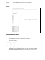
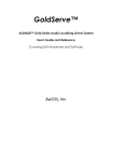
Three Touchdowns Maximum
Die retesting can touch down on a single die three times maximum under certain retest scenarios.
For example:
3 touchdowns on these two die
quad head touchdown 4
quad head touchdown 3
quad head touchdown 2
quad head touchdown 1
retest die
retest die
If the head is scanning from left to right and encounters the left "retest die", it will shift
one die to the right (to put a different site over the die) for retesting.
When the head goes on to encounter the right "retest die", it will shift one die to the left
for retesting -- hence the left "retest die" will experience (the maximum of) three
touchdowns.
5
28Apr06
CTI VT2100-KLA Die Retest Software Notes for Engineering
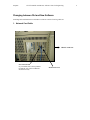
Changing between Old and New Software
Switching back and forth between old and new software consists of moving cables on:
1. Network Card Cable
FRONT of the tool
new network card
(by convention, this is always further
towards the rear of the tool than the
old network card)
old network card
6
28Apr06
CTI VT2100-KLA Die Retest Software Notes for Engineering
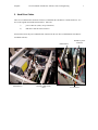
7
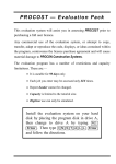
2. Hard Drive Cables
There is a second hard drive under the VT hood, which holds the "Die Retest" retrofitted software. It is
next to the original (non-Die Retest) hard drive. Move the
i)
power connector (white, on top of the drive)
ii)
IDE cable: from the old to new drive.
Pictures below show the power and IDE cable connected to the new drive (which holds the "Die Retest"
retrofitted software):
old hard drive
hard drive power
connector
new hard
drive
old hard drive
Software
hard drive IDE ribbon
cable
new hard drive
28Apr06
CTI VT2100-KLA Die Retest Software Notes for Engineering
8
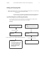
Getting and Analyzing Data
1.
When a wafer finishes on the VT tester, a logfile (containing the run information we are interested in)
will be created. For wafer (e.g.) 251234-01, the logfile is called:
c:\41234-01.log
-
If a previous copy of c:\41234-01.log existed when wafer 2541234-01 finished (e.g.:
a sort2 run), the log information is appended onto the end of the existing file; i.e.:
Log Files Holding Error and Warning Information
Two new logfiles have been created for Die Retest, corresponding to the two (dprc.exe data
transfer, rdpio.exe prober interface) programs which were changed:
Data Flow:
rdpio.exe
- prober interface program
dprc.exe
- transfers data to and from the cti
server
during wafer running
c:\rdpio.log
at wafer completion, create or append, and then delete rdpio.log
c:\41234-01.log
-
Note that these logfiles are not
automatically deleted/purged,
and will eventually fill up the
hard drive if not manually
deleted/purged.
c:\dprc.log
when dprc.log gets too big
c:\dprc.lo1
28Apr06
CTI VT2100-KLA Die Retest Software Notes for Engineering
Software Version Information Contained in the Logfile
Programs dprc.exe and rdpio.exe log their software versions to their respective (c:\dprc.log, c:\rdpio.log)
logfiles every time they are started up; e.g.:
******** starting DPRC.EXE CTI Version 14Dec05 built Dec 14 2005
******** starting RDPIO.EXE CTI 14Dec05 release built Dec 14 2005
Logfile Information about Bin Zeros used if Retest Move Error
Retesting die conssists of:
1. Shifting the test head
2. Touching down and getting another set of test results
3. Shifting the test head back to the original location
4. Telling the system what the bincodes are.
If an error occurs at step 3 above, then a bincode of zero will be issued/posted for all die in the original
touchdown, and the software will then issue commands to proceed onward with testing.
-
An accompanying message will appear in the logfile; e.g.:
WARNING at <15,6>, cannot move to pre-retest loc <14,5>, so zeroing test results
9
28Apr06
CTI VT2100-KLA Die Retest Software Notes for Engineering
2.
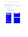
Getting the logfile(s) from the VT tester to your PC via ftp.
a)
Create some directory on your PC to receive the log data, e.g. c:\VT15logs
b) Get the "ip address" of your PC by opening a Dos window and using the command "ipconfig".
c)
When the VT is not running product:
i)
Press the <alt> key,
ii)
then select the "Open Window"
iii)
then select the "Dos Window" option
Open Window
DESQview
Open Window
O
Switch Window
S
Close Window
C
Rearrange
R
Zoom
Mark
M
Transfer
Sissors
Help
Quit DESQview
F1
Q
DOS
DO
10
28Apr06
CTI VT2100-KLA Die Retest Software Notes for Engineering
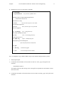
d) Within the Dos screen, issue the follow commands
c:\> cd \ncsaftp
c:\> ftp 157.95.4.178
use your PC's ip address here
National Center for Supercomputing Applications
NCSA FTP 2.3.08 Nov '94
220 FTP Server ready
Username:
enter your PC's ftp server user name
331 Password required for
Password:
.
enter your PC's ftp server password
230 User logged in.
ftp> cd \vt15logs
"cd" = change directory
250 CWD command successful
ftp> lcd \
"lcd" = local change directory
Local directory now C:\
ftp> mput *.log
"mput" = multiple file puts
mput rdpio.log (Yes/No/All/Quit) a
after all of the files have transferred:
ftp> quit
C:\> del *.log
to delete the logfiles
C:\> exit
to exit the Desqview Dos window
Note: You might have to get ahold of MIS to setup your ftp username and password on your PC
3.
Analyzing the logfile
a)
To determine the total number of retests that were done on a wafer, "grep" the log file for the
statement:
"Got RETEST results at"
The number of this times this message exists in the logfile corresponds to the total number of retests
done on the wafer.
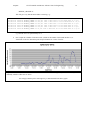
b) To determine the number of bincodes which were lowered due to retesting, "grep" the log file for the
statement:
11
28Apr06
CTI VT2100-KLA Die Retest Software Notes for Engineering
12
"RETEST_CHANGE at"
This will give every bincode lowered due to retesting, e.g.:
Fri
Fri
Fri
Fri
Fri
Fri
Fri
Nov
Nov
Nov
Nov
Nov
Nov
Nov
18
18
18
18
18
18
18
12:43:59
12:48:01
12:49:25
12:50:56
12:51:16
12:53:17
12:56:46
RETEST_CHANGE
RETEST_CHANGE
RETEST_CHANGE
RETEST_CHANGE
RETEST_CHANGE
RETEST_CHANGE
RETEST_CHANGE
at
at
at
at
at
at
at
<34,8> site 2 data bin 8->1 for head move of <1,1>
<30,12> site 2 data bin 8->1 for head move of <-1,1>
<25,12> site 2 data bin 11->8 for head move of <-1,1>
<20,12> site 2 data bin 7->1 for head move of <-1,1>
<19,12> site 4 data bin 8->1 for head move of <1,1>
<12,12> site 2 data bin 7->1 for head move of <-1,1>
<3,16> site 1 data bin 10->1 for head move of <-1,-1>
e.g.: bincode 10 to 1 is represented by 10->1
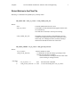
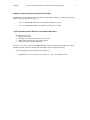
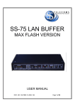
4.
One can plot the "Number of Die Recovered" (which are the number of die turned into bin 1's) vs.
"DateTime" in Excel to determine probe card performance for a series of wafers:
As presented in PCR4 (memo KXF-154 " CTI Die Retest 13Jan06 PCR4 and resulting ARs"), die recovered is only
minimally related to either tester or device.
It is strongly related to probe card longetivity, as demonstrated in the above graph.
28Apr06
CTI VT2100-KLA Die Retest Software Notes for Engineering
Operator Instructions (Spec Updates)
The Die Retest updates to spec 001-02682 ("Fab2 Versatest V210X Operations Procedure") via ECN
417142 are summarized for convenience:
8.2.6 LOADING THE PROGRAM INTO THE VERSATEST:
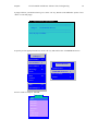
Switching between sessions is done via the "Alt" key, which brings up the following popup:
DESQview
Open Window
O
Switch Window
S
Close Window
C
Rearrange
R
Zoom
Mark
M
Transfer
Sissors
Help
F1
Quit DESQview
Q
Tab to "Switch Window S" (in inverse video above) and press the <enter> key. This brings up the next
window, which permits you to move between the sessions:
V1000 Monitor
- Is the "main menu" function.
- The "F1" key brings up the main menu
Switch Windows
V1000 Monitor
1
V1000 RDP IO Process 2
dprc (cti build)
3
LotList
4
V1000 RDP IO Process
- Displays the wafer map.
- Interfaces with the prober
dprc (cti build)
- Displays plan file (etc.) selection
- Transfers data to the server.
LotList
- Displays a summary of wafers processed.
13
28Apr06
CTI VT2100-KLA Die Retest Software Notes for Engineering
14
From the "V1000 Monitor" session, Press “F1” on the VT keyboard to bring up the "main menu" at the top
of the screen:
Main Menu (in "V1000 Monitor")
V2102
Init Lot
VT24
Utilities
(TX)
MAN
Run Program
<F1>
window Position
test Site
A submenu will appear. Select “ENTER LOT INFORMATION” and press “ENTER”.
MENU
28Apr06
CTI VT2100-KLA Die Retest Software Notes for Engineering
15
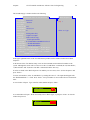
A popup will appear telling you to switch to the "dprc (cti build)" session. Press <enter> to get rid of this
popup,
then press the <alt> key and change to the "dprc (cti build)" session.
DESQview
Open Window
O
Switch Window
S
Close Window
C
Rearrange
R
Zoom
Mark
M
Switch Windows
V1000 Monitor
1
V1000 RDP IO Process 2
dprc (cti build)
3
LotList
4
Transfer
Sissors
Help
Quit DESQview
F1
Q
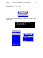
The first time (after rebooting or restarting the software) that this screen is called up, it will first ask you
where the present plan file came from:
28Apr06
CTI VT2100-KLA Die Retest Software Notes for Engineering
16
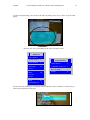
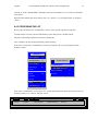
A new screen will appear on the VT monitor. Enter Option "1" (corresponding to "1) Test Plan") and press
“ENTER”.
A popup asking you which directory listing you want will appear, For production, use the up and down
arrows to choose "Production" and then press the <Enter> key.
Select Plan File Path
New Path
[PRODUCTION]
[ENGINEERING]
[LOCAL]
28Apr06
CTI VT2100-KLA Die Retest Software Notes for Engineering
17
A listbox with the plan files will appear on the screen. Use the "<next page>" option to page through the
entries, then arrow to the program that you entered in the program section of the Sort Versatest Traveler.
This information can be obtained from 001-02963 (S23_F_A). When you have selected the correct
program press “ENTER”.
[PRODUCTION]
<previous page>
ft32c64f
ft363220
ft363720
ft36c302
ft36c302.4s
ft36c320
ft36c320.4s
ft36c341
ft36c341.4s
ft36c370
<next page>
Selecting a plan file will clear all of the wafers. To enter a new set of wafer numbers to run, select option
"E) Add Wafer" by typing in "E" and pressing <Enter>
ENTER OPTION ==> E
For each wafer two popups will appear. The first on asks for the wafer number
- Valid wafer numbers are1 through 25 and 99
- The popup will be initialized with: the last wafer number entered + 1.
Wafer number:
2
The second popup asks for the type. We typically leave this blank and just press the
<Enter> key
Wafer type:
Proceed as per the previous two examples, selecting option (numbers of letters), and filling in the
appropriate information.
28Apr06
CTI VT2100-KLA Die Retest Software Notes for Engineering
18
When finished, select the "G) >> Save << " option.
The VT monitor screen will display a listbox with two choices: “YES overlay old stuff" or "NO! keep
what's there". Select “YES overlay old stuff” and press <Enter>.
ARE YOU SURE?
YES overlay old stuff
NO! keep what's there
The system will fetch the appropriate files from the server, unpack and copy them, etc. When the bottom
of the screen displays
"--- Ready for new command ----"
i.e.:
*** PLEASE WAIT *** (sending updates to VOS)
---- Ready for new command ------- Got D_NEW_LOT command ------- Ready for new command ----
Use the <alt> key to go back to the "V1000 Monitor" session
DESQview
Open Window
O
Switch Window
S
Close Window
C
Rearrange
R
M
Transfer
Sissors
Help
Quit DESQview
V1000 Monitor
1
V1000 RDP IO Process 2
Zoom
Mark
Switch Windows
F1
Q
dprc (cti build)
3
LotList
4
28Apr06
CTI VT2100-KLA Die Retest Software Notes for Engineering
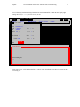
19
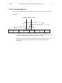
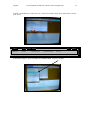
In the Monitor session, there will be a "Test Site" box at the bottom. This box (shown as "Test Site 01"
below) will display information being loaded into the test board hardware. When this box display right
pointing chevrons (i.e.: ">>"), the tester is ready to run.
VT24
V2102
Init Lot
Utilities
Test Head 1
TPG
PLN
Lot
Wafer
8c29000a.cof
F129000a
2009006
01 ( )
Units Tested 0
Units Passed 0
Yield 100%
Status
(TX)
MAN
Run Program
<F1>
window Position
MENU
test Site
site 1 ? %
site 2 ? %
site 3
? %
site 4
? %
Started
Test Site 01
done loading files
>>
On this same screen, verify that the plan file (i.e. "PLN" in the "Test Head 1" box above) is correct for the
device being run.
28Apr06
8.4
CTI VT2100-KLA Die Retest Software Notes for Engineering
20
Production
8.4.1 EDITING WAFER SEQUENCE
If necessary (or if in doubt as to which "Window" you're in), switch to the "V1000 Monitor" screen by
pressing the <alt> key, then using the "Switch Windows" option.
DESQview
Open Window
O
Switch Window
S
Close Window
C
Rearrange
R
Zoom
Mark
M
Switch Windows
V1000 Monitor
1
V1000 RDP IO Process 2
dprc (cti build)
3
LotList
4
Transfer
Sissors
Help
F1
Quit DESQview
Q
Once in the "V1000 Monitor" session, press <F1> to bring up the main menu bar at the top of the screen (if
necessary) and select “INIT LOT”.
VT24
V2102
Init Lot
Utilities
-
(TX)
MAN
Run Program
<F1>
window Position
Select “Wafer Sequence Edit”.
test Site
MENU
28Apr06
CTI VT2100-KLA Die Retest Software Notes for Engineering
21
A popup will appear telling you to switch to the "dprc (cti build)" session. Press <enter> to get rid of this
popup,
then press the <alt> key and change to the "dprc (cti build)" window.
DESQview
Open Window
O
Switch Window
S
Close Window
C
Rearrange
R
Zoom
Mark
M
Transfer
Sissors
Help
Quit DESQview
F1
Q
Switch Windows
V1000 Monitor
1
V1000 RDP IO Process 2
dprc (cti build)
3
LotList
4
28Apr06
CTI VT2100-KLA Die Retest Software Notes for Engineering
22
This should bring up a window similar to the following:
Wafer Sequence
INITIALIZE TEST STATION SETUP
Test Plan
Ft36C370
2) Lot Number 2541234
3) Lot Split
4) Operator ID kxf
5) Load Board 10/36,12,14
6) Probe Card xx
7) Sort Type Wafer (prober XY)
8) Datalog
Capture test output
File type
make Local file copy
A) Device Type 7C6370-QUAD-Sort1
B) Test Pgm P:\VTONLINE\LOADDIR\7C6370.cof
C) Option File -- NONE SPEFICIED -D) Prober File -- NONE SPECIFIED -E) Add Wafer
H) Insert Wafer
K) Next Wafer
F) Remove Last Wfr I) Delete Wafer
L) Prev Wafer
G) >>SAVE<<
J) Erase Sequence M) >>ABORT<<
ENTER OPTION ==>
[01] *
Wafer: 01 Type:
In the upper right hand corner of the Test Station Setup window will be another window titled "Wafer
Sequence".
At the bottom of the "Test Station Setup" screen are the commands used to add wafer numbers to the
system. Although this section will cover how to use the “E) Add Wafer” command, the “H) Insert Wafer”,
“I) Delete Wafer" and “F) Remove Last Wfr” commands work the same way.
If wafers are listed in the "Wafer Sequence" box and they are not correct, select “J) Erase Sequence” and
press <Enter>”.
To enter wafer numbers, select “E) Add Wafer” by entering the letter "E". The input should appear after
the "ENTER OPTION ==>" field. Press <Enter>. Verify lot number is correct and wafers are in numerical
order.
A new window will open. Type in the first wafer number and press <Enter>.
Wafer number:
2
A second window will open. We do not usually enter a "Wafer Type", so just press <Enter> to close the
window and proceed.
Wafer type:
28Apr06
CTI VT2100-KLA Die Retest Software Notes for Engineering
23
Continue to use the “ADD WAFER” command to until the wafer numbers for every wafer to be tested has
been entered.
When all wafer numbers have been entered, select “G) >>SAVE<<” by entering the letter "G" and press
<Enter>.
8.4.3 PROCESSING THE LOT
Refer to OPL 001-02698 (S03_3) FAB2 How to remove wafer from KLA prober for inspection.
Load the cassette of wafers to be tested into the KLA prober and press the “START” button.
The prober will prealign, load and test the wafer automatically.
If the wafer does not start testing automatically, do the following:
If necessary, switch to the "V1000 Monitor" screen by pressing the <alt> key, then using the "Switch
Windows" option.
DESQview
Open Window
O
Switch Window
S
Close Window
C
Rearrange
R
Zoom
Mark
M
Switch Windows
V1000 Monitor
1
V1000 RDP IO Process 2
dprc (cti build)
3
LotList
4
Transfer
Sissors
Help
F1
Quit DESQview
Q
Once in the "V1000 Monitor" session, press <F1> to bring up the main menu bar at the top of the screen (if
necessary) and arrow to “Utilities” and press <Enter>.
V2102
Init Lot
VT24
Utilities
(TX)
MAN
Run Program
<F1>
window Position
test Site
MENU
28Apr06
CTI VT2100-KLA Die Retest Software Notes for Engineering
24
Arrow to “seNd IO Command and press <Enter>.
V2102
Init Lot
VT24
(TX)
Utilities
Utilities
MAN
Run Program
<F1>
window Position
MENU
test Site
pArtial Summary
Clear Summary
Display Bins
Edit Setup
seNd IO Command
Power off
Reset head
Summary w/Clear
Wafer display
eXit Program
A popup will show you which session to go to (via the <alt> key, then the "Switch Window" option). Press
<Enter> to clear this popup:
5
rdpio command (rdpiocmd.bat)
----------------------------------------------------------------------------------------------------------------------------------------------------------change to: "V1000 RDP IO Process"
----------------------------------------------------------------------------------------------------------------------------------------------------------Press any key to continue . . .
28Apr06
CTI VT2100-KLA Die Retest Software Notes for Engineering
25
As per the previous popup's instructions, use the <alt> key and switch to the "V1000 RDP IO Process"
DESQview
Open Window
O
Switch Window
S
Close Window
C
Rearrange
R
Switch Windows
V1000 Monitor
1
V1000 RDP IO Process 2
Zoom
Mark
M
Transfer
dprc (cti build)
3
LotList
4
Sissors
Help
F1
Quit DESQview
Q
Arrow to “Begin Wafer Probing” and press <Enter>.
Select Prober Command:
Download Prober Setup File
Begin Wafer Probing
Pause Probing
Continue Probing
Test Serial Ports
Unload Current Wafer
As the lot is testing, every 5th wafer must receive and pass a microscope inspection before the next 5 wafers
can be tested. The purpose of the inspection is to insure that the setup is still good and that no drifting, misstepping, or probe damage has occurred.
28Apr06
CTI VT2100-KLA Die Retest Software Notes for Engineering
26
The wafer number that the tool is on is shown at the top of the wafer map screen (see section 8.4.3
"Processing the Lot" for displaying this screen).
DATA Bins,
000
|
Lot: 2545614,
Wafer: 24
016
|
Type:
032
|
048
|
HeadLoc:<10,14>
The wafer number shown on the "V1000 Monitor" screen is NOT valid:
•
Since the new Die Retest software
cannot write to this area of the screen,
the "Wafer" number displayed here is
NOT Valid.
•
Use the Wafer number at the top of the
wafer map display instead
DATA Bins,
000
|
Lot: 2545614,
016
|
Wafer: 24
Type:
032
|
048
|
HeadLoc:<10,14>
To remove a wafer for inspection, follow instructions in OPL 001-02633 (S03_5).
DO NOT remove the cassette while the lot is in process.
If the 5th wafer fails inspection, inspect all wafers back to the last know good wafer, determine the cause of
the failure and take the appropriate action (make adjustments to the setup, pull the probe card and restart
the setup, put the VT down to maintenance, etc;)
NOTE: Any time adjustments are made to the set-up, set the KLA to unload after the wafer and do not
continue probing until the wafer has been inspected and the set-up has been verified.
NOTE: All wafers that fail inspection must be noted on the Sort Versatest Traveler. Contact
LPO/Supervisor for assistance with completing 001-02669 (S01_O_A) FAB2 Probe Damage OCAP.
If the 5th wafer passes inspection, the next 5 wafers may be processed.
28Apr06
CTI VT2100-KLA Die Retest Software Notes for Engineering
27
Continue this procedure – processing 5 wafers and inspecting every 5th – until all wafers in the lot have
been processed.
NOTE: EVERY 5TH WAFER IN THE LOT MUST PASS THE MICROSCOPE INSPECTION, PER THE
CRITERIA IN SPEC 001-03021 (S01), BEFORE THE NEXT 5 WAFERS CAN BE PROCESSED.
During processing, wafer data will be displayed on the VT monitor in the form of a line summary. The line
summary will automatically appear when a wafer is processed and unloaded. If the line summary does not
appear on the monitor, press the “ALT” and 4 on the VT keyboard.
Wafer maps should be viewed during processing. The wafer map provides a real-time display of bins for
the current wafer being processed. The wafer map will alert the operator to any site to site issues before the
wafer is finished testing. To view the wafer maps, do the following:
If necessary, switch to the "V1000 Monitor" screen by pressing the <alt> key, then using the "Switch
Windows" option.
DESQview
Open Window
O
Switch Window
S
Close Window
C
Rearrange
R
Zoom
Mark
M
Switch Windows
V1000 Monitor
1
V1000 RDP IO Process 2
dprc (cti build)
3
LotList
4
Transfer
Sissors
Help
F1
Quit DESQview
Q
Once in the "V1000 Monitor" session, press <F1> to bring up the main menu bar at the top of the screen (if
necessary) and arrow to “Utilities” and press <Enter>. The arrow down and select "Wafer display" and
press <Enter>.
V2102
Init Lot
VT24
(TX)
Utilities
Utilities
MAN
Run Program
pArtial Summary
Clear Summary
Display Bins
Edit Setup
seNd IO Command
Power off
Reset head
Summary w/Clear
Wafer display
eXit Program
<F1>
window Position
test Site
MENU
28Apr06
CTI VT2100-KLA Die Retest Software Notes for Engineering
28
A popup will show you which session to go to (via the <alt> key, then the "Switch Window" option). Press
<Enter> to clear this popup:
5
rdpio command (rdpiocmd.bat)
----------------------------------------------------------------------------------------------------------------------------------------------------------change to: "V1000 RDP IO Process"
----------------------------------------------------------------------------------------------------------------------------------------------------------Press any key to continue . . .
As per the previous popup's instructions, use the <alt> key and switch to the "V1000 RDP IO Process"
DESQview
Open Window
O
Switch Window
S
Close Window
C
Rearrange
R
Switch Windows
V1000 Monitor
1
V1000 RDP IO Process 2
Zoom
Mark
dprc (cti build)
3
LotList
4
M
Transfer
Sissors
Help
F1
Quit DESQview
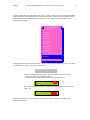
Arrow to “DATA” and press “ENTER”.
Bin type:
Data
Alternate 1
Alternate 2
Alternate 3
Alternate 4
Reject
Legal Opens
Mode Select
Q
28Apr06
CTI VT2100-KLA Die Retest Software Notes for Engineering
29
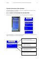
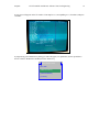
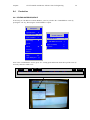
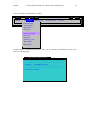
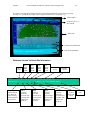
A real-time wafer map will be displayed on the screen with bin information for the wafer being tested.
Pressing <F3> will display the map in a more compressed (and easier to read) form, e.g.:
Wafer number
Location of site 1 of
the test head
Wafer map
Yield and site information
Misc status information
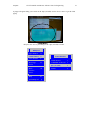
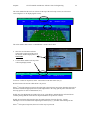
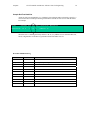
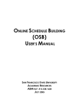
Wafermap Screen Yield and Site Information
Test
Head
Site1
Yield
Total
Yield
#Yield
Test
Head
Site2
Yield
Test
Head
Site3
Yield
Test
Head
Site4
Yield
Total Die
Tested
Total Die
Passed
= 84%(86% 87% 83% 80% ) #Tested= 550 #Passed= 472
#DieLowered= 5 ( 0
Count of die
whose bincode
was lowered
upon retesting
with a different
test head site
2
2
Site1
count of
bincodes
lowered upon
retesting with
another test
head site
1
) #Retests= 10 POST_RETEST_MOVE
Site2
count of
bincodes
lowered upon
retesting with
another test
head site
Site3
count of
bincodes
lowered upon
retesting with
another test
head site
Site4
count of
bincodes
lowered upon
retesting with
another test
head site
Number
of head
shifts and
retests
Retest
state
28Apr06
CTI VT2100-KLA Die Retest Software Notes for Engineering
30
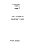
Sample Bad Test Head Site
A bad site will be accompanied by (i) a yield that is lower than the other test head sites, and (ii) a "
count of bincodes lowered upon retesting with another test head site" that is lower than the others.
For example:
#Yield
= 84%(86% 87% 70% 80% ) #Tested= 550 #Passed= 472
#DieLowered= 15 ( 0
2
12
1
) #Retests= 30
shows that site 3 is marking die falsely defective due to (i) a yield that is lower than the other sites,
and (ii) a high number of die that test good when tested with another test site.
Document Modification Log
When
Who
What
18Jan06
kxf
initial version
28Apr06
kxf
new RE_TEST_LIMIT global retest limit description