1
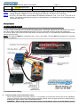
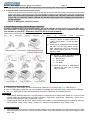
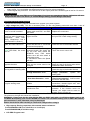
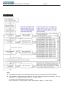
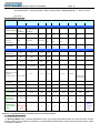
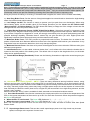
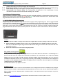
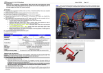
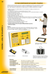
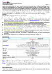
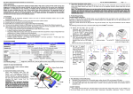
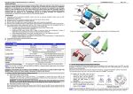
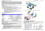
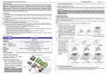
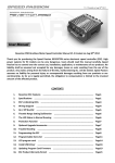
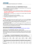
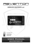
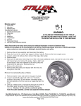
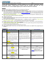
Brushless Motor Speed Controller manual “V1.6-9142010” Page - 1 Thank you for purchasing a Speed Passion GT 2.0 Series Electronic Speed Controller (ESC). High power systems for RC models and can be very dangerous, so we strongly suggest you read this manual carefully. Features: This GT2.0 series ESCs are suitable for any 1/10 1/12 cars and 1/10 trucks. ◆ ESC are compatible with sensored or sensorless brushless motors. ◆ Built in ESC enhancement feature allows you to update to our latest software and future new developments (USB software upgrade kit “Professional LCD program unit PN#SPLCD01” sold separately, please contact your local dealer for more information). Please visit www.speedpassion.net to look for new updated software and features for your GT2.0 series ESC. ◆ Built in new “Green Power version 2.0” feature. A state of the art new development in software to give you extra run time with consistent performance and power. ◆ 4 steps of reverse force. ◆ Smooth proportional brakes with 4 steps of maximum brake adjustment, 8 steps of drag-brake adjustment and 4 steps of initial brake adjustment. ◆ New Digital Racing Response modes (From Level 1 - smooth to Level 9 - aggressive) “Digital Racing Response System - DRRS”. Can be updated for even more driving and track styles. ◆ Multiple protection features: Low voltage cut-off protection for lithium or nickel battery / Over-heat protection / Throttle signal loss protection / Motor locked protection. ◆ “Advanced Multi Timing System - AMTS” special 8 mode active system design gives the best performance possible for any brand of brushless motor. ◆ 2 running modes (Racing mode and Forwards/Reverse mode) ◆ Easily programmable unit with only one setup button and the pocket size SMART ESC programming box included. Specifications: Model Resistance GT 2.0 Pro / GT2.1 EX 0.0003 ohm GT2.0 Pro 4-8 Cell Ni-xx (NiMh or NiCd) or 2-3 Cell Li-Po For 4-6 Cell Ni-xx or 2s Lipo: Use the standard fan supplied with the ESC; Battery BEC Output Motor Type Dimension For 7+ Cell Ni-xx or 3 Cell Lipo: You must disable or change the fan power source because it will be damaged by high voltage. Please choose a high voltage fan or supply the fan from the receiver (+5V); (note 1) GT21. EX 3-6 Cells NiMH or 1 to 2S Li-Po GT2.0 Pro 5.75V/3A GT2.1 EX Built in BEC with Step-up DC/DC booster for 1 cell lipo Racing Sensorless or sensored brushless motor / GT2.0 Pro Supports up to 3.5T brushless motor 4 to 6 cell Ni-xx battery 3.5T above 7 cell Ni-xx battery 5.5T above 2 cell Li-Po battery 4.5T above 3 cell Li-Po battery 7.5T above GT2.1 EX 1/12 3.5T 1 cell or 4NiMH 1/10 Off Road 2 cell or 6 cell NiMH GT2.0 Pro 43mm (L) x 36mm (W) x 33mm ( H) (including fan) GT2.1 EX 43mm(L) 31.75mm(W) x 18.30mm (H) GT 2.0 LPF “Low Profile” 0.0006 ohm GT 2.1 Pro Stock 0.0003 ohm 4-8 Cell Ni-xx (NiMh or NiCd) or 2-3 Cell Li-Po For 4-6 Cell Ni-xx or 2s Lipo: Use the standard fan supplied with the ESC; 4-8 Cell Ni-xx (NiMh or NiCd) or 2-3 Cell Li-Po For 4-6 Cell Ni-xx or 2s Lipo: Use the standard fan supplied with the ESC; For 7+ Cell Ni-xx or 3 Cell Lipo: You must disable or change the fan power source because it will be damaged by high voltage. Please choose a high voltage fan or supply the fan from the receiver (+5V); (note 1) For 7+ Cell Ni-xx or 3 Cell Lipo: You must disable or change the fan power source because it will be damaged by high voltage. Please choose a high voltage fan or supply the fan from the receiver (+5V); (note 1) 5.75V/3A 5.75V/3A Sensorless or sensored brushless motor / Supports up to 5.5T brushless motor on 6 cell 7.2V battery, 5 cell with 4.0T and 4 cell with 3.5T, 3 cell Li-Po battery 9.5T above Sensorless or sensored brushless motor / Supports up to 5.0T brushless motor on 6 cell 7.2V battery, 5 cell with 4.5T and 4 cell with 3.5T, 3 cell Li-Po battery 9.5T above note 2: Standard software on ESC will damage lower than 10.5t motors. 43mm (L) x 36mm (W) x 33mm ( H) (including fan) 43mm (L) x 36mm (W) x 33mm ( H) (including fan) Brushless Motor Speed Controller manual “V1.6-9142010” Weight GT2.0 Pro 65g(w/o wires) GT2.1 EX 60g (w/o wires) ESC Fan: GT2.0 Pro 25MM Page - 2 60g(w/o wires) 70g(w/o wires) 25MM 30MM note 1: The voltage of the ESC fan socket is equal to the voltage of the battery, so please keep in mind that the voltage of battery CANNOT be over the voltage limit of the fan. (6 Cell Ni-xx or 2 Cell Lipo) note 2: The GT2.1 Pro Stock ESC comes loaded with software intended for 10.5t, 11.5t, 13.5t, 17.5t, and 21.5t motors. The special supercharger functions on that software is not intended for, and will damage lower turn motors than 10.5t. Wiring Diagram: Begin To Use The New ESC 1. Connect the ESC, motor, receiver, battery and servo according to the following diagram “+” and “-” wires on the ESC are connected to the battery pack, and the #A, #B and #C are connected to the motor. The “SET” button is used for programming the ESC. The “Fan” connector is used to supply the cooling fan. The receiver cable of the ESC (trio wires with black, red and white color) is connected to the throttle channel of the receiver (Usually CH2). NOTE: The Capacitor MUST be connected to the (+) and (-) of the ESC. The ESC WILL be damaged if it is operated without the capacitor. a) Brushless Motor Wiring Connected with sensored brushless motor When using a brushless motor with a sensor,it is necessary to connect the sensor wires to the “SENSOR” socket on the ESC, because the ESC will automatically identify the motor type (sensored or sensorless) by detecting the signal coming from the SENSOR socket. WARNING! When using sensored brushless motor, the #A, #B, #C wires of the ESC MUST connect Brushless Motor Speed Controller manual “V1.6-9142010” Page - 3 with the motor wire #A, #B, #C respectively. Do not change the wire sequence! Connected with sensorless brushless motor When using a sensorless brushless motor, the #A, #B, #C wires of the ESC can be connected with the motor wires in any order. If the motor runs in the wrong direction, swap any two of the three motor wire connections. Note: You can use the transmitter to set the throttle channel to the “Reverse” direction, and then the motor will run correctly. Please calibrate the throttle range again after changing the direction of throttle channel. Picture A: Wiring with a brushless motor 2. Throttle Range Setting (Throttle Range Calibration) In order to make the ESC fit the throttle range, you must calibrate it when you set up a new ESC, use a new transmitter, or change the ATV or EPA settings of the radio. You must also calibrate after loading new software to your ESC. Otherwise the ESC will not work properly. There are 3 points need to be set, they are full throttle, full brake and the neutral point. *Set the transmitter throttle direction to “REV” on FutabaTM brand transmitters. A) Turn on the transmitter, set the “EPA and ATV” values of throttle channel to “100%” up and down. Turn off any ABS functions. B) Use a pen or screwdriver to hold down the “SET” key and then switch on the ESC, release the “SET” key when the ESC starts beeping and the red LED begins to flash. C) Set the 3 points according to the steps shown as the picture. 1. Neutral point 2. Full Throttle 3. Full Brake D) When the process of calibration is finished, the motor can be started after 3 seconds. 3. LED Status for Normal Running In normal use, if the throttle is in the neutral range, neither the red LED nor the green LED will be lit. The red LED lights up when the car is run forward or backward and it will flash quickly when the car is braking. The green LED lights up when the throttle stick is moved to full throttle or full brakes/reverse. Alert Tones 1. Input voltage abnormal alert tone: The ESC begins to check the input voltage when power on, if it is out of the normal range, the following alert tone will be emitted: “beep-beep-, beep-beep-, beep-beep-” (There is a 1 second interval between every “beep-beep-” tone). 2. Throttle signal abnormal alert tone: When the ESC can’t detect a normal throttle signal, the following alert tone will be emitted: “beep-, beep-, beep-” (There is a 2 second interval between every “beep-” tone). Protection Function 1. Low voltage cut-off protection: If the lithium pack voltage is at or lower than the set cutoff voltage value, the ESC will cut the power to the motor. Please note that the ESC cannot be restarted if the Lipo pack voltage is lower than 7.0V. Brushless Motor Speed Controller manual “V1.6-9142010” 2. 3. Page - 4 Over-heat protection: When the Temperature of the ESC is over 95℃ for 5 seconds, the ESC will cut off the output power. You can disable over-heat protection function for racing competition. Throttle signal loss protection: The ESC will cut off the output power if the throttle signal is lost for 0.2 second. Trouble Shooting ALWAYS Recalibrate your ESC to your Transmitter if you have any operational issues. Calibration will most likely solve the issue. See above: (2. Throttle Range Setting (Throttle Range Calibration) Optional Accessories for Upgrade We provide the following optional accessories to upgrade your power system: 1. High voltage fan (12V): This fan is necessary when you are using battery packs with more than 6 cells of Trouble Possible Reason Solution After power on, motor doesn’t Check the connections between Check the power connections work, no sound is emitted battery pack and ESC, and ESC Replace the connectors and motor. After power on, motor doesn’t Input voltage is abnormal, too Check the voltage of the battery pack work, but emits “beep-beep-, high or too low. and your ESC cutoff voltage setting. alert tone. beep-beep-” (Every “beep-beep-” has a time interval of 1 second ) After power on, the red LED Throttle signal is abnormal – Check the transmitter and the receiver lights, but motor cannot run check that the ESC is connected Check the wire of the throttle channel to the receiver properly. After power on, the red LED & When ESC starts working in Change the sensor cable. green LED flash, but motor sensored mode, But doing the Check the motor sensor unit can run run the ESC have detect the SENSOR error, ESC detect sensor error will auto switch to sensorless mode. In sensorless mode the Speed will drop. The motor runs in the The wire connections between *Only for sensorless brushless motors! opposite direction ESC and the motor need to be Swap any two of the three motor wires changed between the ESC and motor. The motor suddenly stops The throttle signal is lost Check the transmitter and the receiver running while in working state Check the wire of the throttle channel The ESC has entered the “Low The red LED flashes means “low Voltage Protection” Mode voltage protection”, replace the battery pack The ESC has entered the The Green LED flashes means “ Over-heat Protection “ mode “Over-heat protection” , wait for some minutes to cool the ESC Random stop or restart or Some connections are not Check all the connections: battery pack irregular working state reliable connections, throttle signal wire, and motor connections, etc. There is strong Electro - Magnetic Reset the ESC to resume normal interference field. operation. If the function could not resume, you might need to move to another area to run the car. NiMh/NiCd or 2 cell Lipo. It is located on the heat sink of the ESC, it helps to cool the ESC with downward airflow. The picture on the right side shows the installation. WARNING! Please note the fan sold with the ESC can ONLY work with a 2 cell lithium battery pack or 4-6 cell NiMh / NiCd battery pack. Please NEVER use it with a 3-4 cell lithium battery pack or NiMh / NiCd battery pack more than 7 cells, otherwise it may be destroyed. Please check the fan label carefully to confirm its voltage before using it. 2. High capacity filtering capacitors with extreme lowest resistance. Part # SPAMSSC1.5M (4 or 6 Cell Ni-xx or 2 cell Lipo) Part # SPAMSSC3M (4 Cell Ni-xx only) 3. LCD PRO Program card. Brushless Motor Speed Controller manual “V1.6-9142010” Page - 5 Program The ESC 1. Program Method Note: In the program process, the motor will emit “Beep” tones at the same time as the LED is flashes. If the “Number” is bigger than the number “5”, we use a long time flash and long “Beep---” tone to represent “5”, so it is easy to identify the items of the big number. For example, if the LED flashes as the following: “A long time flash + a short time flash” (Motor sounds “Beep---Beep”) = the No. 6 item Brushless Motor Speed Controller manual “V1.6-9142010” Page - 6 “A long time flash + 2 short time flash” (Motor sounds “Beep---BeepBeep”) = the No. 7 item “A long time flash + 3 short time flash” (Motor sounds “Beep---BeepBeepBeep”) = the No. 8 item …… And so on. Programmable Items list Programmable Programmable Value Items Basic Items 1 1. Running Mode 2.Drag Brake Force 3.Low Voltage Cut-Off Threshold 4.Start Mode Advanced Items 5.Maximum Brake Force 6.Maximum Reverse Force 7.Initial Force 2 3 Forward Only with Brake with Brake 0% 5% 10% None 2.6V/Cell 2.8V/Cell Smooth Level 1 4 6 7 8 9 Forward/Reverse Smooth Level 2 Normal Level 3 20% 25% 30% 3.0V 3.2V 3.4V /Cell /Cell /Cell Normal Normal Level 4 Level 5 25% 50% 75% 100% 25% 50% 75% 100% 0% 20% 40% Brake = Drag Brake Force 8.Neutral Range 6% (Narrow) (dead band) 9% (Normal) 9.Timing For both sensored sensorless motor Max runtime 40% 50% Progressive Progressive Aggressive Level 6 Level 7 Level 8 15.00 ° 3.75 ° Aggressive Level 9 12% (Wide) 0.00 ° 10.Over-heat Protection 5 7.50 ° 11.25 ° 26.25° 18.75 ° 22.50° Beware of high temps 95 ℃ Non-Protection Off Stage 1 Stage 2 Stage 3 Stage 4 Stage 5 Stage 6 Stage 7 Max 4000 5000 6000 7000 8000 9000 10000 11000 12000 Off 0.1 0.2 0.3 0.4 0.5 0.6 0.7 11. Reverse 12.Supercharger Boost Level: 13. Supercharger “Start RPM” timing: 14.supercharger Boost opens “Full Throttle” delay – 15.Supercharger “Start Punch” timing: Motor Hot - Max -1 -2 -3 -4 -5 -6 -7 0.8 Motor Cooler Low Attention: The bold italics texts in the above form are the default settings. 2. Programmable Values 2.1. Running Mode: With “Forward with Brake” mode, cars can go forward and brake, but cannot use the reverse function, this mode is suitable for competition; “Forward/Reverse with Brake” mode provides reverse function, which is suitable for practice. Brushless Motor Speed Controller manual “V1.6-9142010” Page - 7 Note: “Forward/Reverse with Brake” mode uses the “double-tap” method to engage reverse, i.e. when you first move the throttle to the brake side, (The 1st “tap”), the ESC begins to brake, but reverse will not engage. When the throttle is moved back to neutral and quickly back to the brake side (The 2nd “tap”), the reverse function will be applied. The “Double-tap” method can prevent mistakenly reversing when the brake function is frequently used. During the process of braking or reversing, if forward throttle is applied, the motor will run forward immediately. 2.2. Auto Drag Brake Force: Set the amount of drag brake applied at neutral throttle to simulate the slight braking effect of a brushed motor while coasting. 2.3. Low Voltage Cut-Off: This function is mainly to prevent your Lipo pack from over discharging. When using lithium battery packs, set the suitable value for low-voltage protection you like. Never use the default value “Non-protection” for lithium battery! The ESC detects the battery’s voltage and if the voltage is lower than the setting threshold, the motor power will be cut off. 2.4. “Digital Racing Response System - DRRS” Digital Racing Mode: Select from “smooth” to “aggressive” start mode as you like. A higher number will provide more punch and more aggressive throttle response. Please note that if you choose “Progressive or Aggressive”” mode, we strongly recommend you’d use good quality battery pack with powerful discharge capability; otherwise these 2 modes may not give the effect you want. Higher punch also significantly increases motor temps and lower punch decreases motor temps. 2.5. Maximum Brake Force: The ESC provides a proportional brake function. The brake force is related to the position of the throttle stick. Maximum brake force refers to the force applied at full brake on your transmitter. A very large brake force can shorten the brake time, but it may damage the gears. 2.6. Maximum Reverse Force: Sets how much power will be applied in the reverse direction. Different value gives different reverse speeds. 2.7. Initial Brake Force: It is also called “minimum brake force”, and it refers to the force when the throttle stick is located at the initial position of the braking zone. The default value is equal to the drag brake force, so the brake effect can be applied smoothly. 2.8. Throttle Neutral Range (dead band): Please see the following illustrations to adjust the neutral range as your like. 2.9. “Advanced Multi Timing System - AMTS”: There are many differences among brushless motors, racing surfaces and car types. A fixed (high or low) timing ESC is not ideal for all situations, so we have made the timing value programmable. Please select the most suitable timing value according to the brand and wind of the motor you are using. Generally, higher timing values may bring out higher power output, but at the expense of excess motor heat. Generally the faster the motor (lower turns, or higher Kv) the less tolerant it is to high timing advance, and the quicker it may overheat. Please note that the “timing” value is available for both sensored and sensorless brushless motors. 2.10. Over-Heat Protection: If the function is activated, the output power will be cut-off when the temperature of the ESC or the internal temperature of the motor is up to 95ºC for more than 5 seconds. When the protection happens, the Green LED will light. When the ESC is over-heated: The Green LED flashes as “☆----☆----☆----”. When the motor is over-heated: The Green LED flashes as “☆-☆----☆-☆----☆-☆----”. Note: The over-heat protection function for the motor may not be 100% accurate for motors other than Speed Passion brand. 2.1.2 Supercharger Boost Level: This sets the overall supercharger power level. High levels may increase speed, but always at the expense of motor heat. Brushless Motor Speed Controller manual “V1.6-9142010” Page - 8 2.1.3 Supercharger RPM Delay: This controls when the supercharger settings engage. When the motor RPM 2.1.4 2.1.5 reaches this setting, the ESC will engage the supercharger. Supercharger Punch: This setting controls the supercharger function at RPMs below the Start RPM setting. Lower settings decrease motor temps, and higher settings increase punch and motor temps. Supercharger Full Throttle Delay: This setting delays the application of the supercharger function until after a set time has been reached while holding FULL Throttle. Reset All Items To Default Values At any time when the throttle is located at neutral (except in the throttle calibration or parameters program process), hold the “SET” key for over 3 seconds, the red LED and green LED will flash at the same time , which means each programmable item has be reset to its original default value. 3. Set The ESC By Using Program Card Programming the ESC trackside is easy and fast with the pocket sized programming box. When a programmable value needs to be changed, just plug the receiver wire of the ESC into the socket of the program card (The socket is on the right corner, and marked with +- ), connect the main battery pack to the ESC and turn on the ESC switch. Each item’s current value will be shown on the program card. Use the “ITEM” and “VALUE” buttons to select the programmable items and new values, and then press the “OK” button to set the new choices in the ESC software. Caution: 1. Do not operate the ESC at voltages lower than 4.8V or higher the 8.4V battery, damage to the ESC can result. 2. When mounting the brushless motor in your car, pay careful attention to the length of the motor screws, they must not exceed 4.0mm in depth, longer than this and internal damage to the motor will result, which will void the product warranty. 3. Ensure all connections are secure before using this product. ESC product warranty period: 90 days limited warranty, This product is guaranteed to be free from defects in materials or workmanship for a period of 90 days form the original date of purchase (Verified by sale receipt dated). User accepts all resulting liability. We reserve the right to modify warranty provisions without notice. Warranty does not cover incorrect installation, components worn by use, or any damage caused by crash, flooding or natural disaster. The company has no control over the installation of this product; no liability may be assumed nor will be accepted for any damage resulting from the use of this product. 2 month return time for any repair or services Exemption Clause: Speed Passion does not have control over the installation or use of this product therefore no liability for any damages incurred in its use will be accepted. Operation of this product is at the user’s risk. The use of R/C models requires a degree of skill; if you are a beginner please consult the advice of an experienced user to prevent injury to goods or other persons. Please visit www.SpeedPassion.net for updated ESC information and new software update releases!