1
MELSEC iQ-R CPU Module User's Manual
(Startup)
-R04CPU
-R04ENCPU
-R08CPU
-R08ENCPU
-R08PCPU
-R08SFCPU
-R16CPU
-R16ENCPU
-R16PCPU
-R16SFCPU
-R32CPU
-R32ENCPU
-R32PCPU
-R32SFCPU
-R120CPU
-R120ENCPU
-R120PCPU
-R120SFCPU
-R6SFM
SAFETY PRECAUTIONS
(Read these precautions before using this product.)
Before using this product, please read this manual and the relevant manuals carefully and pay full attention to safety to handle
the product correctly.
In this manual, the safety precautions are classified into two levels: "
WARNING" and "
CAUTION".
WARNING
Indicates that incorrect handling may cause hazardous conditions, resulting in
death or severe injury.
CAUTION
Indicates that incorrect handling may cause hazardous conditions, resulting in
minor or moderate injury or property damage.
Under some circumstances, failure to observe the precautions given under "
CAUTION" may lead to serious
consequences.
Observe the precautions of both levels because they are important for personal and system safety.
Make sure that the end users read this manual and then keep the manual in a safe place for future reference.
1
[Design Precautions]
WARNING
● Configure safety circuits external to the programmable controller to ensure that the entire system
operates safely even when a fault occurs in the external power supply or the programmable controller.
Failure to do so may result in an accident due to an incorrect output or malfunction.
(1) Emergency stop circuits, protection circuits, and protective interlock circuits for conflicting
operations (such as forward/reverse rotations or upper/lower limit positioning) must be configured
external to the programmable controller.
(2) When the programmable controller detects an abnormal condition, it stops the operation and all
outputs are:
• Turned off if the overcurrent or overvoltage protection of the power supply module is activated.
• Held or turned off according to the parameter setting if the self-diagnostic function of the CPU
module detects an error such as a watchdog timer error.
(3) All outputs may be turned on if an error occurs in a part, such as an I/O control part, where the
CPU module cannot detect any error. To ensure safety operation in such a case, provide a safety
mechanism or a fail-safe circuit external to the programmable controller. For a fail-safe circuit
example, refer to "General Safety Requirements" in the MELSEC iQ-R Module Configuration
Manual.
(4) Outputs may remain on or off due to a failure of a component such as a relay and transistor in an
output circuit. Configure an external circuit for monitoring output signals that could cause a
serious accident.
● In an output circuit, when a load current exceeding the rated current or an overcurrent caused by a
load short-circuit flows for a long time, it may cause smoke and fire. To prevent this, configure an
external safety circuit, such as a fuse.
● Configure a circuit so that the programmable controller is turned on first and then the external power
supply. If the external power supply is turned on first, an accident may occur due to an incorrect output
or malfunction.
● For the operating status of each station after a communication failure, refer to manuals relevant to the
network. Incorrect output or malfunction due to a communication failure may result in an accident.
● When connecting an external device with a CPU module or intelligent function module to modify data
of a running programmable controller, configure an interlock circuit in the program to ensure that the
entire system will always operate safely. For other forms of control (such as program modification,
parameter change, forced output, or operating status change) of a running programmable controller,
read the relevant manuals carefully and ensure that the operation is safe before proceeding. Improper
operation may damage machines or cause accidents.
2
[Design Precautions]
WARNING
● Especially, when a remote programmable controller is controlled by an external device, immediate
action cannot be taken if a problem occurs in the programmable controller due to a communication
failure. To prevent this, configure an interlock circuit in the program, and determine corrective actions
to be taken between the external device and CPU module in case of a communication failure.
● Do not write any data to the "system area" and "write-protect area" of the buffer memory in the
module. Also, do not use any "use prohibited" signals as an output signal from the CPU module to
each module. Doing so may cause malfunction of the programmable controller system. For the
"system area", "write-protect area", and the "use prohibited" signals, refer to the user's manual for the
module used.
● If a communication cable is disconnected, the network may be unstable, resulting in a communication
failure of multiple stations. Configure an interlock circuit in the program to ensure that the entire
system will always operate safely even if communications fail. Failure to do so may result in an
accident due to an incorrect output or malfunction.
● To maintain the safety of the programmable controller system against unauthorized access from
external devices via the network, take appropriate measures. To maintain the safety against
unauthorized access via the Internet, take measures such as installing a firewall.
[Precautions for using Safety CPUs]
● When the safety programmable controller detects a fault in the external power supply or itself, it turns
off all outputs in the safety system. Configure an external circuit to ensure that the power source of a
hazard is shut off by turning off the outputs. Failure to do so may result in an accident.
● Configure short current protection circuits for a safety relay and protection circuits, such as a fuse and
breaker, external to the safety programmable controller.
● When a load current exceeding the rated current or an overcurrent caused by a load short-circuit
flows, the CC-Link IE Field Network remote I/O module (with safety functions) detects an error and
turns off all outputs. Note that if the overcurrent state continues for a long time, it may cause smoke
and fire. To prevent this, configure an external safety circuit, such as a fuse.
● When changing data and operating status, and modifying program of the running safety
programmable controller from an external device such as a personal computer connected to the
Safety CPU, configure an interlock circuit in the program or external to the safety programmable
controller to ensure that the entire system always operates safely. In addition, determine corrective
actions to be taken between the external device and Safety CPU in case of a communication failure
during online operations due to poor contact of cables.
● Do not use any "use prohibited" signals as a remote I/O signal since they are used in the system. Do
not write any data to the "use prohibited" areas in the remote register. For the "use prohibited" signals,
refer to the MELSEC iQ-R CC-Link IE Field Network User's Manual (Application). Do not turn on or off
these signals on a program since normal operations cannot be guaranteed. Doing so may cause
malfunction of the programmable controller system.
● When the CC-Link IE Field Network remote I/O module (with safety functions) detects a CC-Link IE
Field Network error, it turns off outputs. However, the outputs in a program are not automatically
turned off. Create a program that turns off the outputs when a CC-Link IE Field Network error has
been detected. If the CC-Link IE Field Network is restored with the outputs on, a machine may
suddenly operate and result in an accident.
3
[Design Precautions]
WARNING
● Create an interlock circuit which uses reset buttons so that the system does not restart automatically
after executing safety functions and turning off outputs.
● In the case of a communication failure in the network, the status of the error station will be as follows:
(1) All inputs from remote I/O stations are turned off.
(2) All outputs from remote I/O stations are turned off.
Check the communication status information and configure an interlock circuit in the program to
ensure that the entire system will operate safely. Failure to do so may result in an accident due to an
incorrect output or malfunction.
● Outputs may remain on or off due to a failure of the CC-Link IE Field Network remote I/O module (with
safety functions). Configure an external circuit for monitoring output signals that could cause a serious
accident.
[Design Precautions]
CAUTION
● Do not install the control lines or communication cables together with the main circuit lines or power
cables. Keep a distance of 100mm or more between them. Failure to do so may result in malfunction
due to noise.
● During control of an inductive load such as a lamp, heater, or solenoid valve, a large current
(approximately ten times greater than normal) may flow when the output is turned from off to on.
Therefore, use a module that has a sufficient current rating.
● After the CPU module is powered on or is reset, the time taken to enter the RUN status varies
depending on the system configuration, parameter settings, and/or program size. Design circuits so
that the entire system will always operate safely, regardless of the time.
● Do not power off the programmable controller or reset the CPU module while the settings are being
written. Doing so will make the data in the flash ROM and SD memory card undefined. The values
need to be set in the buffer memory and written to the flash ROM and SD memory card again. Doing
so also may cause malfunction or failure of the module.
● When changing the operating status of the CPU module from external devices (such as the remote
RUN/STOP functions), select "Do Not OPEN in Program" for "Open Method Setting" in the module
parameters. If "OPEN in Program" is selected, an execution of the remote STOP function causes the
communication line to close. Consequently, the CPU module cannot reopen the line, and external
devices cannot execute the remote RUN function.
[Precautions for using Safety CPUs]
● When selecting external devices to be connected to the CC-Link IE Field Network remote I/O module
(with safety functions), consider the maximum inrush current described in the CC-Link IE Field
Network Remote I/O Module (With Safety Functions) User's Manual.
[Installation Precautions]
WARNING
● Shut off the external power supply (all phases) used in the system before mounting or removing the
module. Failure to do so may result in electric shock or cause the module to fail or malfunction.
4
[Installation Precautions]
CAUTION
● Use the programmable controller in an environment that meets the general specifications in the Safety
Guidelines included with the base unit. Failure to do so may result in electric shock, fire, malfunction,
or damage to or deterioration of the product.
● To mount a module, place the concave part(s) located at the bottom onto the guide(s) of the base unit,
and push in the module until the hook(s) located at the top snaps into place. Incorrect interconnection
may cause malfunction, failure, or drop of the module.
● To mount a module with no module fixing hook, place the concave part(s) located at the bottom onto
the guide(s) of the base unit, push in the module, and fix it with screw(s).
● When using the programmable controller in an environment of frequent vibrations, fix the module with
a screw.
● Tighten the screws within the specified torque range. Undertightening can cause drop of the screw,
short circuit, or malfunction. Overtightening can damage the screw and/or module, resulting in drop,
short circuit, or malfunction.
● When using an extension cable, connect it to the extension cable connector of the base unit securely.
Check the connection for looseness. Poor contact may cause malfunction.
● When using an SD memory card, fully insert it into the SD memory card slot. Check that it is inserted
completely. Poor contact may cause malfunction.
● Securely insert an extended SRAM cassette into the cassette connector of the CPU module. After
insertion, close the cassette cover and check that the cassette is inserted completely. Poor contact
may cause malfunction.
● Do not directly touch any conductive parts and electronic components of the module, SD memory
card, extended SRAM cassette, or connector. Doing so can cause malfunction or failure of the
module.
[Precautions for using Safety CPUs]
● Use the CC-Link IE Field Network remote I/O module (with safety functions) in an environment that
meets the general specifications in the CC-Link IE Field Network Remote I/O Module (With Safety
Functions) User's Manual. Use the CC-Link IE Field Network remote I/O module in an environment
that meets the general specifications in the CC-Link IE Field Network Remote I/O Module User's
Manual. Failure to do so may result in electric shock, fire, malfunction, or damage to or deterioration of
the product.
● Securely fix the CC-Link IE Field Network remote I/O module (with safety functions) or CC-Link IE
Field Network remote I/O module with a DIN rail or module fixing screws. Tighten the screws within
the specified torque range. Undertightening can cause drop of the screw, short circuit, or malfunction.
Overtightening can damage the screw and/or module, resulting in drop, short circuit, or malfunction.
[Wiring Precautions]
WARNING
● Shut off the external power supply (all phases) used in the system before installation and wiring.
Failure to do so may result in electric shock or cause the module to fail or malfunction.
● After installation and wiring, attach the included terminal cover to the module before turning it on for
operation. Failure to do so may result in electric shock.
5
[Wiring Precautions]
CAUTION
● Individually ground the FG and LG terminals of the programmable controller with a ground resistance
of 100 ohms or less. Failure to do so may result in electric shock or malfunction.
● Use applicable solderless terminals and tighten them within the specified torque range. If any spade
solderless terminal is used, it may be disconnected when the terminal screw comes loose, resulting in
failure.
● Check the rated voltage and signal layout before wiring to the module, and connect the cables
correctly. Connecting a power supply with a different voltage rating or incorrect wiring may cause fire
or failure.
● Connectors for external devices must be crimped or pressed with the tool specified by the
manufacturer, or must be correctly soldered. Incomplete connections may cause short circuit, fire, or
malfunction.
● Securely connect the connector to the module. Poor contact may cause malfunction.
● Do not install the control lines or communication cables together with the main circuit lines or power
cables. Keep a distance of 100mm or more between them. Failure to do so may result in malfunction
due to noise.
● Place the cables in a duct or clamp them. If not, dangling cable may swing or inadvertently be pulled,
resulting in damage to the module or cables or malfunction due to poor contact. Do not clamp the
extension cables with the jacket stripped.
● Check the interface type and correctly connect the cable. Incorrect wiring (connecting the cable to an
incorrect interface) may cause failure of the module and external device.
● Tighten the terminal screws or connector screws within the specified torque range. Undertightening
can cause drop of the screw, short circuit, fire, or malfunction. Overtightening can damage the screw
and/or module, resulting in drop, short circuit, fire, or malfunction.
● When disconnecting the cable from the module, do not pull the cable by the cable part. For the cable
with connector, hold the connector part of the cable. For the cable connected to the terminal block,
loosen the terminal screw. Pulling the cable connected to the module may result in malfunction or
damage to the module or cable.
● Prevent foreign matter such as dust or wire chips from entering the module. Such foreign matter can
cause a fire, failure, or malfunction.
● A protective film is attached to the top of the module to prevent foreign matter, such as wire chips,
from entering the module during wiring. Do not remove the film during wiring. Remove it for heat
dissipation before system operation.
● Programmable controllers must be installed in control panels. Connect the main power supply to the
power supply module in the control panel through a relay terminal block. Wiring and replacement of a
power supply module must be performed by qualified maintenance personnel with knowledge of
protection against electric shock. For wiring, refer to the MELSEC iQ-R Module Configuration Manual.
6
[Startup and Maintenance Precautions]
WARNING
● Do not touch any terminal while power is on. Doing so will cause electric shock or malfunction.
● Correctly connect the battery connector. Do not charge, disassemble, heat, short-circuit, solder, or
throw the battery into the fire. Also, do not expose it to liquid or strong shock. Doing so will cause the
battery to produce heat, explode, ignite, or leak, resulting in injury and fire.
● Shut off the external power supply (all phases) used in the system before cleaning the module or
retightening the terminal screws, connector screws, or module fixing screws. Failure to do so may
result in electric shock.
7
[Startup and Maintenance Precautions]
CAUTION
● When connecting an external device with a CPU module or intelligent function module to modify data
of a running programmable controller, configure an interlock circuit in the program to ensure that the
entire system will always operate safely. For other forms of control (such as program modification,
parameter change, forced output, or operating status change) of a running programmable controller,
read the relevant manuals carefully and ensure that the operation is safe before proceeding. Improper
operation may damage machines or cause accidents.
● Especially, when a remote programmable controller is controlled by an external device, immediate
action cannot be taken if a problem occurs in the programmable controller due to a communication
failure. To prevent this, configure an interlock circuit in the program, and determine corrective actions
to be taken between the external device and CPU module in case of a communication failure.
● Do not disassemble or modify the modules. Doing so may cause failure, malfunction, injury, or a fire.
● Use any radio communication device such as a cellular phone or PHS (Personal Handy-phone
System) more than 25cm away in all directions from the programmable controller. Failure to do so
may cause malfunction.
● Shut off the external power supply (all phases) used in the system before mounting or removing the
module. Failure to do so may cause the module to fail or malfunction.
● Tighten the screws within the specified torque range. Undertightening can cause drop of the
component or wire, short circuit, or malfunction. Overtightening can damage the screw and/or module,
resulting in drop, short circuit, or malfunction.
● After the first use of the product, do not mount/remove the module to/from the base unit, and the
terminal block to/from the module, and do not insert/remove the extended SRAM cassette to/from the
CPU module more than 50 times (IEC 61131-2 compliant) respectively. Exceeding the limit may cause
malfunction.
● After the first use of the product, do not insert/remove the SD memory card to/from the CPU module
more than 500 times. Exceeding the limit may cause malfunction.
● Do not touch the metal terminals on the back side of the SD memory card. Doing so may cause
malfunction or failure of the module.
● Do not touch the integrated circuits on the circuit board of an extended SRAM cassette. Doing so may
cause malfunction or failure of the module.
● Do not drop or apply shock to the battery to be installed in the module. Doing so may damage the
battery, causing the battery fluid to leak inside the battery. If the battery is dropped or any shock is
applied to it, dispose of it without using.
● Startup and maintenance of a control panel must be performed by qualified maintenance personnel
with knowledge of protection against electric shock. Lock the control panel so that only qualified
maintenance personnel can operate it.
● Before handling the module, touch a conducting object such as a grounded metal to discharge the
static electricity from the human body. Failure to do so may cause the module to fail or malfunction.
8
[Operating Precautions]
CAUTION
● When changing data and operating status, and modifying program of the running programmable
controller from an external device such as a personal computer connected to an intelligent function
module, read relevant manuals carefully and ensure the safety before operation. Incorrect change or
modification may cause system malfunction, damage to the machines, or accidents.
[Disposal Precautions]
CAUTION
● When disposing of this product, treat it as industrial waste.
● When disposing of batteries, separate them from other wastes according to the local regulations. For
details on battery regulations in EU member states, refer to the MELSEC iQ-R Module Configuration
Manual.
[Transportation Precautions]
CAUTION
● When transporting lithium batteries, follow the transportation regulations. For details on the regulated
models, refer to the MELSEC iQ-R Module Configuration Manual.
● The halogens (such as fluorine, chlorine, bromine, and iodine), which are contained in a fumigant
used for disinfection and pest control of wood packaging materials, may cause failure of the product.
Prevent the entry of fumigant residues into the product or consider other methods (such as heat
treatment) instead of fumigation. The disinfection and pest control measures must be applied to
unprocessed raw wood.
9
CONDITIONS OF USE FOR THE PRODUCT
(1) Mitsubishi programmable controller ("the PRODUCT") shall be used in conditions;
i) where any problem, fault or failure occurring in the PRODUCT, if any, shall not lead to any major or serious accident;
and
ii) where the backup and fail-safe function are systematically or automatically provided outside of the PRODUCT for the
case of any problem, fault or failure occurring in the PRODUCT.
(2) The PRODUCT has been designed and manufactured for the purpose of being used in general industries.
MITSUBISHI SHALL HAVE NO RESPONSIBILITY OR LIABILITY (INCLUDING, BUT NOT LIMITED TO ANY AND ALL
RESPONSIBILITY OR LIABILITY BASED ON CONTRACT, WARRANTY, TORT, PRODUCT LIABILITY) FOR ANY
INJURY OR DEATH TO PERSONS OR LOSS OR DAMAGE TO PROPERTY CAUSED BY the PRODUCT THAT ARE
OPERATED OR USED IN APPLICATION NOT INTENDED OR EXCLUDED BY INSTRUCTIONS, PRECAUTIONS, OR
WARNING CONTAINED IN MITSUBISHI'S USER, INSTRUCTION AND/OR SAFETY MANUALS, TECHNICAL
BULLETINS AND GUIDELINES FOR the PRODUCT.
("Prohibited Application")
Prohibited Applications include, but not limited to, the use of the PRODUCT in;
• Nuclear Power Plants and any other power plants operated by Power companies, and/or any other cases in which the
public could be affected if any problem or fault occurs in the PRODUCT.
• Railway companies or Public service purposes, and/or any other cases in which establishment of a special quality
assurance system is required by the Purchaser or End User.
• Aircraft or Aerospace, Medical applications, Train equipment, transport equipment such as Elevator and Escalator,
Incineration and Fuel devices, Vehicles, Manned transportation, Equipment for Recreation and Amusement, and
Safety devices, handling of Nuclear or Hazardous Materials or Chemicals, Mining and Drilling, and/or other
applications where there is a significant risk of injury to the public or property.
Notwithstanding the above, restrictions Mitsubishi may in its sole discretion, authorize use of the PRODUCT in one or
more of the Prohibited Applications, provided that the usage of the PRODUCT is limited only for the specific
applications agreed to by Mitsubishi and provided further that no special quality assurance or fail-safe, redundant or
other safety features which exceed the general specifications of the PRODUCTs are required. For details, please
contact the Mitsubishi representative in your region.
• For Safety CPUs
(1) Although MELCO has obtained the certification for Product's compliance to the international safety standards
IEC61508, EN954-1/ISO13849-1 from TUV Rheinland, this fact does not guarantee that Product will be free from any
malfunction or failure. The user of this Product shall comply with any and all applicable safety standard, regulation or
law and take appropriate safety measures for the system in which the Product is installed or used and shall take the
second or third safety measures other than the Product. MELCO is not liable for damages that could have been
prevented by compliance with any applicable safety standard, regulation or law.
(2) MELCO prohibits the use of Products with or in any application involving, and MELCO shall not be liable for a default, a
liability for defect warranty, a quality assurance, negligence or other tort and a product liability in these applications.
(a) power plants,
(b) trains, railway systems, airplanes, airline operations, other transportation systems,
(c) hospitals, medical care, dialysis and life support facilities or equipment,
(d) amusement equipments,
(e) incineration and fuel devices,
(f) handling of nuclear or hazardous materials or chemicals,
(g) mining and drilling,
(h) and other applications where the level of risk to human life, health or property are elevated.
10
INTRODUCTION
Thank you for purchasing the Mitsubishi MELSEC iQ-R series programmable controllers.
This manual describes the performance specifications, procedures before operation, and troubleshooting of the relevant
products listed below.
Before using this product, please read this manual and the relevant manuals carefully and develop familiarity with the
functions and performance of the MELSEC iQ-R series programmable controller to handle the product correctly.
Please make sure that the end users read this manual.
Relevant products
Item
Model
CPU module
R04CPU, R04ENCPU, R08CPU, R08ENCPU, R08PCPU, R08SFCPU, R16CPU, R16ENCPU, R16PCPU,
R16SFCPU, R32CPU, R32ENCPU, R32PCPU, R32SFCPU, R120CPU, R120ENCPU, R120PCPU,
R120SFCPU
Extended SRAM cassette
NZ2MC-1MBS, NZ2MC-2MBS, NZ2MC-4MBS, NZ2MC-8MBS, NZ2MC-16MBS, NZ2MC-8MBSE
Safety function module
R6SFM
COMPLIANCE WITH EMC AND LOW VOLTAGE
DIRECTIVES
Method of ensuring compliance
To ensure that Mitsubishi programmable controllers maintain EMC and Low Voltage Directives when incorporated into other
machinery or equipment, certain measures may be necessary. Please refer to one of the following manuals.
• MELSEC iQ-R Module Configuration Manual
• Safety Guidelines (This manual is included with the base unit.)
The CE mark on the side of the programmable controller indicates compliance with EMC and Low Voltage Directives.
Additional measures
To ensure that this product maintains EMC and Low Voltage Directives, please refer to one of the following manuals.
• MELSEC iQ-R Module Configuration Manual
• Safety Guidelines (This manual is included with the base unit.)
COMPLIANCE WITH THE MACHINERY DIRECTIVE
Method of ensuring compliance
To ensure that Mitsubishi safety programmable controllers maintain Machinery Directive when incorporated into other
machinery or equipment, certain measures may be necessary. Please refer to one of the following manuals.
• MELSEC iQ-R Module Configuration Manual
• Safety Guidelines (This manual is included with the base unit.)
The CE mark on the side of the safety programmable controller indicates compliance with Machinery Directive.
Additional measures
To ensure that this product maintains Machinery Directive, please refer to one of the following manuals.
• MELSEC iQ-R Module Configuration Manual
• Safety Guidelines (This manual is included with the base unit.)
11
CONTENTS
SAFETY PRECAUTIONS . . . . . . . . . . . . . . . . . . . . . . . . . . . . . . . . . . . . . . . . . . . . . . . . . . . . . . . . . . . . . . . . . . . .1
CONDITIONS OF USE FOR THE PRODUCT . . . . . . . . . . . . . . . . . . . . . . . . . . . . . . . . . . . . . . . . . . . . . . . . . . .10
INTRODUCTION . . . . . . . . . . . . . . . . . . . . . . . . . . . . . . . . . . . . . . . . . . . . . . . . . . . . . . . . . . . . . . . . . . . . . . . . . . 11
COMPLIANCE WITH EMC AND LOW VOLTAGE DIRECTIVES . . . . . . . . . . . . . . . . . . . . . . . . . . . . . . . . . . . . . 11
COMPLIANCE WITH THE MACHINERY DIRECTIVE . . . . . . . . . . . . . . . . . . . . . . . . . . . . . . . . . . . . . . . . . . . . . 11
RELEVANT MANUALS . . . . . . . . . . . . . . . . . . . . . . . . . . . . . . . . . . . . . . . . . . . . . . . . . . . . . . . . . . . . . . . . . . . . .14
TERMS . . . . . . . . . . . . . . . . . . . . . . . . . . . . . . . . . . . . . . . . . . . . . . . . . . . . . . . . . . . . . . . . . . . . . . . . . . . . . . . . .15
CHAPTER 1
PART NAMES
17
1.1
CPU Module . . . . . . . . . . . . . . . . . . . . . . . . . . . . . . . . . . . . . . . . . . . . . . . . . . . . . . . . . . . . . . . . . . . . . . . . . . . . 17
1.2
Extended SRAM Cassette. . . . . . . . . . . . . . . . . . . . . . . . . . . . . . . . . . . . . . . . . . . . . . . . . . . . . . . . . . . . . . . . . 22
1.3
Safety Function Module . . . . . . . . . . . . . . . . . . . . . . . . . . . . . . . . . . . . . . . . . . . . . . . . . . . . . . . . . . . . . . . . . . 23
CHAPTER 2
SPECIFICATIONS
24
2.1
CPU Module . . . . . . . . . . . . . . . . . . . . . . . . . . . . . . . . . . . . . . . . . . . . . . . . . . . . . . . . . . . . . . . . . . . . . . . . . . . . 24
2.2
Extended SRAM Cassette. . . . . . . . . . . . . . . . . . . . . . . . . . . . . . . . . . . . . . . . . . . . . . . . . . . . . . . . . . . . . . . . . 31
2.3
Safety Function Module . . . . . . . . . . . . . . . . . . . . . . . . . . . . . . . . . . . . . . . . . . . . . . . . . . . . . . . . . . . . . . . . . . 32
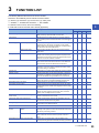
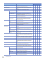
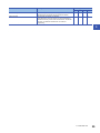
CHAPTER 3
FUNCTION LIST
33
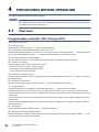
CHAPTER 4
PROCEDURES BEFORE OPERATION
36
4.1
Overview. . . . . . . . . . . . . . . . . . . . . . . . . . . . . . . . . . . . . . . . . . . . . . . . . . . . . . . . . . . . . . . . . . . . . . . . . . . . . . . 36
Programmable controller CPU, Process CPU . . . . . . . . . . . . . . . . . . . . . . . . . . . . . . . . . . . . . . . . . . . . . . . . . . . 36
Safety CPU . . . . . . . . . . . . . . . . . . . . . . . . . . . . . . . . . . . . . . . . . . . . . . . . . . . . . . . . . . . . . . . . . . . . . . . . . . . . . 37
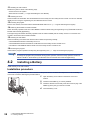
4.2
Installing a Battery . . . . . . . . . . . . . . . . . . . . . . . . . . . . . . . . . . . . . . . . . . . . . . . . . . . . . . . . . . . . . . . . . . . . . . 38
Installation procedure . . . . . . . . . . . . . . . . . . . . . . . . . . . . . . . . . . . . . . . . . . . . . . . . . . . . . . . . . . . . . . . . . . . . . 38
4.3
Inserting or Removing an Extended SRAM Cassette . . . . . . . . . . . . . . . . . . . . . . . . . . . . . . . . . . . . . . . . . . 39
Insertion procedure . . . . . . . . . . . . . . . . . . . . . . . . . . . . . . . . . . . . . . . . . . . . . . . . . . . . . . . . . . . . . . . . . . . . . . . 39
Removal procedure . . . . . . . . . . . . . . . . . . . . . . . . . . . . . . . . . . . . . . . . . . . . . . . . . . . . . . . . . . . . . . . . . . . . . . . 39
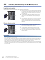
4.4
Inserting and Removing an SD Memory Card . . . . . . . . . . . . . . . . . . . . . . . . . . . . . . . . . . . . . . . . . . . . . . . . 40
Insertion procedure . . . . . . . . . . . . . . . . . . . . . . . . . . . . . . . . . . . . . . . . . . . . . . . . . . . . . . . . . . . . . . . . . . . . . . . 40
Removal procedure . . . . . . . . . . . . . . . . . . . . . . . . . . . . . . . . . . . . . . . . . . . . . . . . . . . . . . . . . . . . . . . . . . . . . . . 40
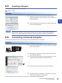
4.5
Creating a Project . . . . . . . . . . . . . . . . . . . . . . . . . . . . . . . . . . . . . . . . . . . . . . . . . . . . . . . . . . . . . . . . . . . . . . . 41
4.6
Connecting a Personal Computer . . . . . . . . . . . . . . . . . . . . . . . . . . . . . . . . . . . . . . . . . . . . . . . . . . . . . . . . . . 41
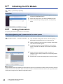
4.7
Initializing the CPU Module . . . . . . . . . . . . . . . . . . . . . . . . . . . . . . . . . . . . . . . . . . . . . . . . . . . . . . . . . . . . . . . 42
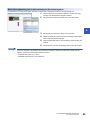
4.8
Setting Parameters . . . . . . . . . . . . . . . . . . . . . . . . . . . . . . . . . . . . . . . . . . . . . . . . . . . . . . . . . . . . . . . . . . . . . . 42
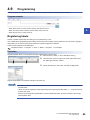
4.9
Programming . . . . . . . . . . . . . . . . . . . . . . . . . . . . . . . . . . . . . . . . . . . . . . . . . . . . . . . . . . . . . . . . . . . . . . . . . . . 45
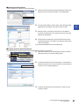
Registering labels . . . . . . . . . . . . . . . . . . . . . . . . . . . . . . . . . . . . . . . . . . . . . . . . . . . . . . . . . . . . . . . . . . . . . . . . 45
Inserting program elements. . . . . . . . . . . . . . . . . . . . . . . . . . . . . . . . . . . . . . . . . . . . . . . . . . . . . . . . . . . . . . . . . 46
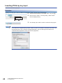
Inserting POUs by key input . . . . . . . . . . . . . . . . . . . . . . . . . . . . . . . . . . . . . . . . . . . . . . . . . . . . . . . . . . . . . . . . 48
4.10
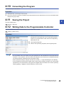
Converting the Program . . . . . . . . . . . . . . . . . . . . . . . . . . . . . . . . . . . . . . . . . . . . . . . . . . . . . . . . . . . . . . . . . . 49
4.11
Saving the Project . . . . . . . . . . . . . . . . . . . . . . . . . . . . . . . . . . . . . . . . . . . . . . . . . . . . . . . . . . . . . . . . . . . . . . . 49
4.12
Writing Data to the Programmable Controller . . . . . . . . . . . . . . . . . . . . . . . . . . . . . . . . . . . . . . . . . . . . . . . . 49
4.13
Resetting the CPU Module . . . . . . . . . . . . . . . . . . . . . . . . . . . . . . . . . . . . . . . . . . . . . . . . . . . . . . . . . . . . . . . . 50
4.14
Executing the Program . . . . . . . . . . . . . . . . . . . . . . . . . . . . . . . . . . . . . . . . . . . . . . . . . . . . . . . . . . . . . . . . . . . 50
4.15
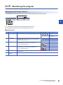
Monitoring the program . . . . . . . . . . . . . . . . . . . . . . . . . . . . . . . . . . . . . . . . . . . . . . . . . . . . . . . . . . . . . . . . . . 51
4.16
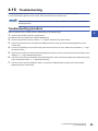
Troubleshooting . . . . . . . . . . . . . . . . . . . . . . . . . . . . . . . . . . . . . . . . . . . . . . . . . . . . . . . . . . . . . . . . . . . . . . . . 53
Troubleshooting procedure . . . . . . . . . . . . . . . . . . . . . . . . . . . . . . . . . . . . . . . . . . . . . . . . . . . . . . . . . . . . . . . . . 53
12
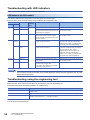
Troubleshooting with LED indicators . . . . . . . . . . . . . . . . . . . . . . . . . . . . . . . . . . . . . . . . . . . . . . . . . . . . . . . . . . 54
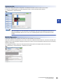
Troubleshooting using the engineering tool. . . . . . . . . . . . . . . . . . . . . . . . . . . . . . . . . . . . . . . . . . . . . . . . . . . . . 54
APPENDIX
57
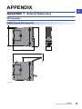
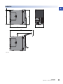
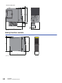
Appendix 1 External Dimensions . . . . . . . . . . . . . . . . . . . . . . . . . . . . . . . . . . . . . . . . . . . . . . . . . . . . . . . . . . . . . . . . 57
CPU module . . . . . . . . . . . . . . . . . . . . . . . . . . . . . . . . . . . . . . . . . . . . . . . . . . . . . . . . . . . . . . . . . . . . . . . . . . . . 57
Safety function module . . . . . . . . . . . . . . . . . . . . . . . . . . . . . . . . . . . . . . . . . . . . . . . . . . . . . . . . . . . . . . . . . . . . 60
62
REVISIONS . . . . . . . . . . . . . . . . . . . . . . . . . . . . . . . . . . . . . . . . . . . . . . . . . . . . . . . . . . . . . . . . . . . . . . . . . . . . . .64
WARRANTY . . . . . . . . . . . . . . . . . . . . . . . . . . . . . . . . . . . . . . . . . . . . . . . . . . . . . . . . . . . . . . . . . . . . . . . . . . . . .65
TRADEMARKS . . . . . . . . . . . . . . . . . . . . . . . . . . . . . . . . . . . . . . . . . . . . . . . . . . . . . . . . . . . . . . . . . . . . . . . . . . .68
CONTENTS
INDEX
13
RELEVANT MANUALS
Manual name [manual number]
Description
Available form
MELSEC iQ-R CPU Module User's Manual (Startup)
[SH-081263ENG] (this manual)
Performance specifications, procedures before operation, and
troubleshooting of the CPU module
Print book
MELSEC iQ-R CPU Module User's Manual (Application)
[SH-081264ENG]
Memory, functions, devices, and parameters of the CPU
module
Print book
e-Manual
EPUB
PDF
e-Manual
EPUB
PDF
This manual does not include detailed information on the following:
• General specifications
• Applicable CPU modules and the number of mountable modules
• Installation
For details, refer to the following.
MELSEC iQ-R Module Configuration Manual
e-Manual refers to the Mitsubishi FA electronic book manuals that can be browsed using a dedicated tool.
e-Manual has the following features:
• Required information can be cross-searched in multiple manuals.
• Other manuals can be accessed from the links in the manual.
• The hardware specifications of each part can be found from the product figures.
• Pages that users often browse can be bookmarked.
14
TERMS
Unless otherwise specified, this manual uses the following terms.
Term
Description
CPU module
A generic term for the MELSEC iQ-R series CPU module
FB instance
A function block that is inserted to a sequence program
RAS
The abbreviation for Reliability, Availability, and Serviceability. This term refers to the overall usability of
automated equipment.
RnCPU
A generic term for the R04CPU, R08CPU, R16CPU, R32CPU, and R120CPU
RnENCPU
A generic term for the R04ENCPU, R08ENCPU, R16ENCPU, R32ENCPU, and R120ENCPU
RnENCPU (CPU part)
A module on the left-hand side of the RnENCPU ( MELSEC iQ-R Ethernet/CC-Link IE User's
Manual (Startup))
RnENCPU (network part)
A module on the right-hand side of the RnENCPU ( MELSEC iQ-R Ethernet/CC-Link IE User's
Manual (Startup))
Safety CPU
A generic term for the R08SFCPU, R16SFCPU, R32SFCPU, and R120SFCPU.
This module is used with a safety function module as a pair, and performs both standard control and
safety control.
Safety function module
Another term for the R6SFM.
This module is used with the Safety CPU as a pair and performs safety control. The module can only be
paired with the Safety CPU.
Intelligent function module
A module that has functions other than input and output, such as an A/D converter module and D/A
converter module
Engineering tool
Another term for the software package for the MELSEC programmable controllers
Global label
A label that is valid for all the program data when multiple program data are created in the project.
There are two types of global label: a module specific label (module label), which is generated
automatically by GX Works3, and an optional label, which can be created for any specified device.
Programmable controller CPU
A generic term for the R04CPU, R04ENCPU, R08CPU, R08ENCPU, R16CPU, R16ENCPU, R32CPU,
R32ENCPU, R120CPU, and R120ENCPU
Device
A device (X, Y, M, D, or others) in a CPU module
Power supply module
A generic term for the MELSEC iQ-R series power supply modules
I/O module
A generic term for the input module, output module, I/O combined module, and interrupt module
Network module
A generic term for the following modules:
• Ethernet interface module
• CC-Link IE Controller Network module
• Module on CC-Link IE Field Network
• MELSECNET/H network module
• MELSECNET/10 network module
• RnENCPU (network part)
POU
A unit that configures a program. Units are categorized and provided in accordance with functions. Use
of POUs enables dividing the lower-layer processing in a hierarchical program into some units in
accordance with processing or functions, and creating programs for each unit.
Program block
A group of POUs that configure a program
Process CPU
A generic term for the R08PCPU, R16PCPU, R32PCPU, and R120PCPU
Base unit
A generic term for main base units, extension base units, and RQ extension base units
Module label
A label that represents one of memory areas (I/O signals and buffer memory areas) specific to each
module in a given character string. For the module used, GX Works3 automatically generates this label,
which can be used as a global label.
Label
A label that represents a device in a given character string
15
The following terms are used to explain a safety programmable controller system using the Safety CPU.
16
Term
Description
Safety programmable controller
A generic term for the MELSEC iQ-R series modules that perform safety control (such as a Safety CPU,
safety function module, CC-Link IE Field Network remote I/O module (with safety functions))
Safety control
Machine control by safety programs and safety data communications. When an error occurs, the
machine in operation is securely stopped.
Safety communications
Communication service that performs send/receive processing in the safety layer of the safety
communication protocol
Safety device
A device that can be used in safety programs
Safety program
A program that performs safety control
Standard CPU
A generic term for MELSEC iQ-R series CPU modules (other than Safety CPU) that perform standard
control (This term is used to distinguish from the Safety CPU.)
Standard programmable controller
A generic term for MELSEC iQ-R series modules that perform standard control (This term is used to
distinguish from a safety programmable controller.)
Standard control
Machine control by standard programs and standard data communications. Programmable controllers
other than the safety programmable controller perform only standard control. (This term is used to
distinguish from safety control.)
Standard communications
Communications other than safety communications, such as cyclic transmission and transient
transmission of CC-Link IE Field Network
Standard device
A device (X, Y, M, D, or others) in a CPU module. (Safety devices are excluded.) This device can be
used only in standard programs. (This term is used to distinguish from a safety device.)
Standard program
A program that performs sequence control. (Safety programs are excluded.) (This term is used to
distinguish from a safety program.)
Pair version
Version information to determine the Safety CPU and safety function module used as a pair
1
1.1
PART NAMES
1
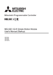
CPU Module
This section describes the part names of the CPU module.
1 PART NAMES
1.1 CPU Module
17
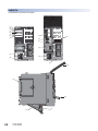
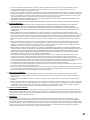
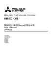
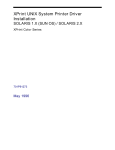
RnCPU, Process CPU, Safety CPU
The R04CPU is used as an example.
(1)
(2)
(3)
(4)
(5)
(6)
(7)
(8)
(13)
(12)
(11)
(14)
(9)
(15)
(10)
(21)
(19)
(18)
(20)
(16)
18
1 PART NAMES
1.1 CPU Module
(17)
No.
Name
Description
(1)
READY LED
(2)
ERROR LED
Indicates the operating status of the CPU module and the error level. ( Page 54 LED status of the CPU
module)
● READY LEDERROR LED status
Onoff: Normal operation
Onon: Minor error
Onflashing: Moderate error
Flashingon: Minor error (Changing module online)
Flashing (every 2s)off: Initial processing
Flashing (every 400ms)off: Changing module online
Offon/flashing: Major error
(3)
PROGRAM RUN LED
Indicates the operating status of the program.
On: Being executed (RUN state)
Flashing: Being suspended (PAUSE state)
Off: Stopped (STOP state) or stop error
(4)
USER LED
Indicates the status of the annunciator (F). ( MELSEC iQ-R CPU Module User's Manual (Application))
On: Annunciator (F) on
Off: Normal operation
(5)
BATTERY LED
Indicates the battery status.
Flashing: Battery low
Off: Normal operation
(6)
CARD READY LED
Indicates the availability of the SD memory card.
On: Available
Flashing: Ready
Off: Not available or not inserted
(7)
CARD ACCESS LED
Indicates the access status of the SD memory card.
On: Being accessed
Off: Not accessed
(8)
FUNCTION LED
Indicates the status of the function being executed. ( MELSEC iQ-R CPU Module User's Manual
(Application))
(9)
SPEED LED
Refer to the following.
MELSEC iQ-R Ethernet/CC-Link IE User's Manual (Startup)
(10)
SD/RD LED
(11)
RUN/STOP/RESET switch
A switch for controlling the operating status of the CPU module ( Page 50 Executing the Program)
RUN: Executes the program.
STOP: Stops the program.
RESET: Resets the CPU module. (Keep the switch in the RESET position for approximately one second.)
Operate the RUN/STOP/RESET switch with your fingers. To prevent the switch from being damaged, do not
use any tool such as a screwdriver.
(12)
SD memory card access control
switch
A switch for disabling access to the SD memory card to remove it from the CPU module ( Page 40
Inserting and Removing an SD Memory Card)
(13)
SD memory card slot
A slot where an SD memory card is inserted
(14)
USB port*1
A connector for a USB-compatible peripheral (connector type: miniB)
(15)
Ethernet port
Refer to the following.
MELSEC iQ-R Ethernet/CC-Link IE User's Manual (Startup)
(16)
Battery
A backup battery to hold clock data and to use the backup power function for the device/label memory
(17)
Battery connector pin
A pin for connecting a lead wire of the battery
(To save the battery, the lead wire is disconnected from the connector before shipment.)
(18)
Cassette cover
A cover for the connector where an extended SRAM cassette is inserted. To use an extended SRAM cassette,
open the cover, and insert the cassette. ( Page 39 Inserting or Removing an Extended SRAM Cassette)
(19)
LED cover
A cover for the LED indicators, SD memory card slot, and switches. Open this cover and insert or remove an
SD memory card or set the RUN/STOP/RESET switch.
Otherwise, keep the cover closed to prevent entry of foreign matter such as dust.
(20)
USB cover
A cover for the USB port. Open this cover and connect a USB-compatible peripheral.
Otherwise, keep the cover closed to prevent entry of foreign matter such as dust.
Production information marking
Shows the production information (16 digits) of the module.
(21)
*1
1
When a cable is connected to the USB connector at all times, clamp the cable to prevent a poor connection, moving, and disconnection
by unintentional pulling.
1 PART NAMES
1.1 CPU Module
19
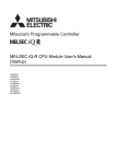
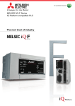
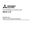
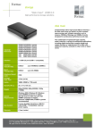
RnENCPU
The R04ENCPU is used as an example.
(1)
(2)
(3)
(4)
(5)
(6)
(7)
(8)
(13)
(22)
(12)
(11)
(14)
(9)
(15)
(10)
(21)
(19)
(18)
(20)
(16)
20
1 PART NAMES
1.1 CPU Module
(17)
No.
Name
Description
(1)
READY LED
(2)
ERROR LED
Indicates the operating status of the CPU module and the error level. ( Page 54 LED status of the CPU
module)
● READY LEDERROR LED status
Onoff: Normal operation
Onon: Minor error
Onflashing: Moderate error
Flashingoff: Initial processing
Offon/flashing: Major error
(3)
PROGRAM RUN LED
Indicates the operating status of the program.
On: Being executed (RUN state)
Flashing: Being suspended (PAUSE state)
Off: Stopped (STOP state) or stop error
(4)
USER LED
Indicates the status of the annunciator (F). ( MELSEC iQ-R CPU Module User's Manual (Application))
On: Annunciator (F) on
Off: Normal operation
(5)
BATTERY LED
Indicates the battery status.
Flashing: Battery low
Off: Normal operation
(6)
CARD READY LED
Indicates the availability of the SD memory card.
On: Available
Flashing: Ready
Off: Not available or not inserted
(7)
CARD ACCESS LED
Indicates the access status of the SD memory card.
On: Being accessed
Off: Not accessed
(8)
FUNCTION LED
Indicates the status of the function being executed. ( MELSEC iQ-R CPU Module User's Manual
(Application))
(9)
SPEED LED
Refer to the following.
MELSEC iQ-R Ethernet/CC-Link IE User's Manual (Startup)
(10)
SD/RD LED
(11)
RUN/STOP/RESET switch
A switch for controlling the operating status of the CPU module ( Page 50 Executing the Program)
RUN: Executes the program.
STOP: Stops the program.
RESET: Resets the CPU module. (Keep the switch in the RESET position for approximately one second.)
Operate the RUN/STOP/RESET switch with your fingers. To prevent the switch from being damaged, do not
use any tool such as a screwdriver.
(12)
SD memory card access control
switch
A switch for disabling access to the SD memory card to remove it from the CPU module ( Page 40
Inserting and Removing an SD Memory Card)
(13)
SD memory card slot
A slot where an SD memory card is inserted
(14)
USB port*1
A connector for a USB-compatible peripheral (connector type: miniB)
(15)
Ethernet port (CPU P1)
Refer to the following.
MELSEC iQ-R Ethernet/CC-Link IE User's Manual (Startup)
(16)
Battery
A backup battery to hold clock data and to use the backup power function for the device/label memory
(17)
Battery connector pin
A pin for connecting a lead wire of the battery
(To save the battery, the lead wire is disconnected from the connector before shipment.)
(18)
Cassette cover
A cover for the connector where an extended SRAM cassette is inserted. To use an extended SRAM cassette,
open the cover, and insert the cassette. ( Page 39 Inserting or Removing an Extended SRAM Cassette)
(19)
LED cover
A cover for the LED indicators, SD memory card slot, and switches. Open this cover and insert or remove an
SD memory card or set the RUN/STOP/RESET switch.
Otherwise, keep the cover closed to prevent entry of foreign matter such as dust.
(20)
USB cover
A cover for the USB port. Open this cover and connect a USB-compatible peripheral.
Otherwise, keep the cover closed to prevent entry of foreign matter such as dust.
(21)
Production information marking
Shows the production information (16 digits) of the module.
(22)
Network part
Refer to the following.
MELSEC iQ-R Ethernet/CC-Link IE User's Manual (Startup)
*1
1
When a cable is connected to the USB connector at all times, clamp the cable to prevent a poor connection, moving, and disconnection
by unintentional pulling.
1 PART NAMES
1.1 CPU Module
21
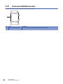
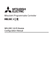
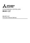
1.2
Extended SRAM Cassette
This section describes the part names of the extended SRAM cassette.
(1)
22
No.
Name
Description
(1)
Tab for cassette insertion/removal
A part which is held when an extended SRAM cassette is inserted or removed
1 PART NAMES
1.2 Extended SRAM Cassette
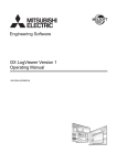
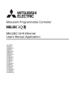
1.3
Safety Function Module
1
This section describes the part names of the safety function module.
(1)
(2)
(3)
(4)
(5)
(6)
(7)
No.
Name
Description
(1)
READY LED
(2)
ERROR LED
Indicates the operating status of the CPU module and the error level of the safety control. ( Page 54 LED
status of the CPU module)
● READY LEDERROR LED status
Onoff: Normal operation
Onon: Minor error
Onflashing: Moderate error
Offon/flashing: Major error
(3)
PROGRAM RUN LED
Indicates the operating status of safety programs.
On: Safety program being executed
Off: Safety program not executed or stopped
(4)
SAFETY COM RUN LED
Indicates the status of safety communications.
On: Safety communications being executed
Off: Safety communications not executed or stopped
(5)
SAFETY COM ERR LED
Indicates the status of safety communications.
On: Error during safety communications
Off: No error
(6)
TEST LED
Indicates the status in TEST MODE.
On: TEST MODE
Flashing: SAFETY MODE (wait-for-restart)
Off: SAFETY MODE
(7)
Production information marking
Shows the production information (16 digits) of the module.
1 PART NAMES
1.3 Safety Function Module
23
2
SPECIFICATIONS
2.1
CPU Module
This section describes the specifications of the CPU module.
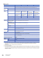
Hardware specifications
■Programmable controller CPU, Process CPU
Item
R04CPU,
R04ENCPU
Operation control method
Stored program cyclic operation
I/O control mode
Refresh mode
(The direct access input/output is available by specifying the direct access input/output (DX, DY).)
Instruction
processing
time
LD X0
0.98ns
MOV D0 D1
1.96ns
Instruction
processing
time
(structured
text)
IF
1.96ns
CASE
1.96ns
FOR
1.96ns
Memory
capacity
Program capacity
40K steps
(160K bytes)
80K steps
(320K bytes)
160K steps
(640K bytes)
320K steps
(1280K bytes)
1200K steps
(4800K bytes)
Program memory
160K bytes
320K bytes
640K bytes
1280K bytes
4800K bytes
SD memory card
Device/label
memory
Number of
storable files
R32CPU,
R32ENCPU,
R32PCPU
R120CPU,
R120ENCPU,
R120PCPU
Differs depending on the SD memory card used. (SD/SDHC memory card: 32G bytes maximum)
400K bytes
Device area*1
80K bytes
Label area*1
60K bytes
Latch label area*1
4K bytes
File storage area*1
256K bytes
1024K bytes
1536K bytes
2048K bytes
3072K bytes
Data memory
2M bytes
5M bytes
10M bytes
20M bytes
40M bytes
CPU buffer memory
1072K bytes (536K words) (including the fixed scan communication area (24K words))
Refresh memory
2048K bytes*2
Program memory
(P: number of program files, FB: number
of FB files)
188
(P: 124, FB: 64
(One FB file can
store 64 function
blocks.))
Device/label memory (file storage area)
324 (with or without an extended SRAM cassette)*3
Data memory
256*4
Data memory
SD memory card
1188K bytes
1720K bytes
2316K bytes
3380K bytes
80K bytes
100K bytes
180K bytes
220K bytes
8K bytes
380
(P: 252, FB: 128 (One FB file can store 64 function blocks.))
512*4
• NZ1MEM-2GBSD: 256*4
• NZ1MEM-4GBSD and later: 32767*4
256*4
512*4
• NZ1MEM-2GBSD: 256*4
• NZ1MEM-4GBSD and later: 32767*4
USB port
USB2.0 High Speed (miniB)1
Ethernet port
Refer to the following.
MELSEC iQ-R Ethernet/CC-Link IE User's Manual (Startup)
Clock function
Year, month, date, hour, minute, second, and day of the week (automatic leap year adjustment)
-1.00 to +1.00s/d at 0 to 55
Number of occupied I/O points
RnENCPU (network part): 32
Allowable momentary power failure time
The time differs depending on the power supply module used. ( MELSEC iQ-R Module
Configuration Manual)
Internal current consumption (5VDC)
24
R16CPU,
R16ENCPU,
R16PCPU
Total
SD memory card
Number of
storable
folders
R08CPU,
R08ENCPU,
R08PCPU
2 SPECIFICATIONS
2.1 CPU Module
• RnCPU: 0.67A
• RnENCPU: 1.49A
• Process CPU: 0.76A
Item
External
dimensions
R04CPU,
R04ENCPU
Height
Width
Depth
Weight
*1
*2
*3
*4
R08CPU,
R08ENCPU,
R08PCPU
R16CPU,
R16ENCPU,
R16PCPU
R32CPU,
R32ENCPU,
R32PCPU
R120CPU,
R120ENCPU,
R120PCPU
106mm (Base unit mounting side: 98mm)
• RnCPU, Process CPU: 27.8mm
• RnENCPU: 56mm
2
110mm
• RnCPU, Process CPU: 0.20kg
• RnENCPU: 0.40kg
The capacity of device area, label area, latch label area, and file storage area can be changed in parameter. The capacity of the device/
label memory can be increased by inserting an extended SRAM cassette. ( MELSEC iQ-R CPU Module User's Manual
(Application))
This is the total capacity of the device area and module label area.
System files are included.
The number indicates the number of files and folders (including system files and system folders) can be created in the root directory on
the condition that the number of characters in the file or folder name is 13 or less. In a subdirectory, up to 32767 folders can be created.
Note that the number of storable files and folders will decrease if many folders with a long name, more than 13 characters (including an
extension), are created.
For the hardware specifications of the RnENCPU (network part), refer to the following.
MELSEC iQ-R Ethernet/CC-Link IE User's Manual (Startup)
2 SPECIFICATIONS
2.1 CPU Module
25
■Safety CPU
Item
R08SFCPU
Operation control method
Stored program cyclic operation
I/O control mode
Refresh mode
(The direct access input/output is available by specifying the direct access input/output (DX, DY).)
R32SFCPU
R120SFCPU
Instruction
processing
time
LD SA\X0
0.98ns
MOV SA\D0 SA\D1
1.96ns
Memory
capacity
Program capacity
80K steps (320K bytes)
(For safety programs:
40K steps (160K bytes))
160K steps (640K bytes)
(For safety programs:
40K steps (160K bytes))
320K steps (1280K
bytes)
(For safety programs:
40K steps (160K bytes))
1200K steps (4800K
bytes)
(For safety programs:
40K steps (160K bytes))
Program memory
320K bytes
(For safety programs:
160K bytes)
640K bytes
(For safety programs:
160K bytes)
1280K bytes
(For safety programs:
160K bytes)
4800K bytes
(For safety programs:
160K bytes)
Device/label memory*1
1178K bytes
1710K bytes
2306K bytes
3370K bytes
Data memory
5M bytes
10M bytes
20M bytes
40M bytes
Number of
storable files
CPU buffer memory
1024K bytes (512K words) (including the built-in function information area capacity 4M bytes (2K words))
Refresh memory
2048K bytes*2
Program memory
(P: number of program files,
FB: number of FB files)
380 (including safety programs)
(P: 252, FB: 128 (One FB file can store 64 function blocks.))
Program memory
(P: number of safety program
files, FB: number of safety FB
files)
48
(P: 32, FB: 16 (One FB file can store 64 function blocks.))
Device/label memory (file
storage area)
323 (with or without an extended SRAM cassette)*3
Data memory
512*4
SD memory card
Number of
storable folders
Data memory
SD memory card
• NZ1MEM-2GBSD: 256*4
• NZ1MEM-4GBSD and later: 32767*4
512*4
• NZ1MEM-2GBSD: 256*4
• NZ1MEM-4GBSD and later: 32767*4
USB port
USB2.0 High Speed (miniB)1
Ethernet port
Refer to the following.
MELSEC iQ-R Ethernet/CC-Link IE User's Manual (Startup)
Clock function
Year, month, date, hour, minute, second, and day of the week (automatic leap year adjustment)
-1.00 to +1.00s/d at 0 to 55
Allowable momentary power failure time
The time differs depending on the power supply module used. ( MELSEC iQ-R Module Configuration
Manual)
Internal current consumption (5VDC)
0.76A
External
dimensions
Height
106mm (Base unit mounting side: 98mm)
Width
27.8mm
Depth
110mm
Weight
*1
*2
*3
*4
26
R16SFCPU
0.20kg
The capacity of device area, label area, latch label area, and file storage area can be changed in parameter. The capacity of the device/
label memory can be increased by inserting an extended SRAM cassette. ( MELSEC iQ-R CPU Module User's Manual
(Application))
This is the total capacity of the device area and module label area.
System files are included.
The number indicates the number of files and folders (including system files and system folders) can be created in the root directory on
the condition that the number of characters in the file or folder name is 13 or less. In a subdirectory, up to 32767 folders can be created.
Note that the number of storable files and folders will decrease if many folders with a long name, more than 13 characters (including an
extension), are created.
2 SPECIFICATIONS
2.1 CPU Module
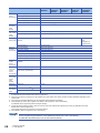
Programming specifications
■Programmable controller CPU, Process CPU
Item
R04CPU,
R04ENCPU
R08CPU,
R08ENCPU,
R08PCPU
R16CPU,
R16ENCPU,
R16PCPU
R32CPU,
R32ENCPU,
R32PCPU
Programming language
Ladder diagram (LD), sequential function chart (SFC)*5, structured text (ST), function block
diagram (FBD/LD)
Programming supporting function
Function block (FB), label programming (system/local/global)
Program
operation
Execution type
Initial execution type, scan execution type, fixed scan execution type, event execution type,
standby type
Type of interrupt
Internal timer interrupt (I28 to I31), high-speed internal timer interrupt 1 (I49), high-speed internal
timer interrupt 2 (I48), interrupt by modules, inter-module synchronous interrupt (I44), multiple CPU
synchronous interrupt (I45)*6
Number of executable programs
124
252
Number of FB files
64
128
Tact
performance
0.2 to 2000ms (The value can be set in increments of 0.1ms.)
Timer
performance
Constant scan
Fixed scan
interrupt
Interrupt using the
internal timer (I28 to
I31)
0.5 to 1000ms (The value can be set in increments of 0.5ms.)
High-speed internal
timer interrupt 1 (I49)
0.05 to 1000ms (The value can be set in increments of 0.05ms.)
High-speed internal
timer interrupt 2 (I48)
0.05 to 1000ms (The value can be set in increments of 0.05ms.)
Inter-module
synchronous interrupt
(I44)
0.1 to 10.00ms (The value can be set in increments of 0.05ms.)
Multiple CPU
synchronous interrupt
(I45)*6
0.1 to 10.00ms (The value can be set in increments of 0.05ms.)
Low-speed timer
1 to 1000ms (Default: 100ms)
High-speed timer
0.01 to 100ms (Default: 10ms)
Long timer
0.001 to 1000ms (Default: 0.001ms)
Number of I/O points
4096 points
Number of
user device
points
(default)
Input (X)
12288 points (fixed)
Output (Y)
12288 points (fixed)
Internal relay (M)
12288 points (user-changeable)*1
Latch relay (L)
8192 points (user-changeable)*1
Link relay (B)
8192 points (user-changeable)*1
Link special relay (SB)
2048 points (user-changeable)*1
Annunciator (F)
2048 points (user-changeable)*1
Edge relay (V)
2048 points (user-changeable)*1
*4*5
Retentive timer
device
Counter device
2
0 points (user-changeable)*1
Step relay (S)
Timer device
R120CPU,
R120ENCPU,
R120PCPU
Timer (T)
1024 points (user-changeable)*1
Long timer (LT)
1024 points (user-changeable)*1
Retentive timer (ST)
0 points (user-changeable)*1
Long retentive timer
(LST)
0 points (user-changeable)*1
Counter (C)
512 points (user-changeable)*1
Long counter (LC)
512 points (user-changeable)*1
Data register (D)
18432 points (user-changeable)*1
Link register (W)
8192 points (user-changeable)*1
Link special register (SW)
2048 points (user-changeable)*1
2 SPECIFICATIONS
2.1 CPU Module
27
Item
R04CPU,
R04ENCPU
Number of
system
device points
R08CPU,
R08ENCPU,
R08PCPU
R16CPU,
R16ENCPU,
R16PCPU
Special relay (SM)
4096 points (fixed)
Special register (SD)
4096 points (fixed)
Function input (FX)
16 points (fixed)
Function output (FY)
16 points (fixed)
Function register (FD)
5 points 4 words (fixed)
Number of
file register
points
(default)
File register (R/ZR)
0 points (user-changeable)*1
Number of
index register
points
(default)
Index register (Z)
20 points (user-changeable, up to 24 points)
Long index register (LZ)
2 points (user-changeable, up to 12 points)
Number of
pointer points
Pointer (P) (global/local)
(default)
8192 points (user-changeable, up to 16384 points)
Interrupt pointer (I)
1024 points (fixed)
Link input (J\X)
16384 points maximum*2
Link output (J\Y)
16384 points maximum*2
Link relay (J\B)
32768 points maximum*2
Link register (J\W)
131072 points maximum*2
Link special relay (J\SB)
512 points maximum*2
Link special register (J\SW)
512 points maximum*2
Intelligent function module device
(U\G)
268435456 points maximum*2
Number of
link direct
device points
Number of
module
access
device points
Buffer memory (U3E\G)
524288 points
Fixed scan communication area in the
buffer memory (U3E\HG)
12288 points maximum*3
Number of
refresh data
register
points
(default)
Refresh data register (RD)
524288 points (1048576 points maximum)
Number of
nesting points
Nesting (N)
15 points
Number of
other device
points
SFC block device (BL)*4*5
Number of
CPU buffer
memory
access
device points
*1
*2
*3
*4
*5
*6
SFC transition device
(TR)*4*5
R32CPU,
R32ENCPU,
R32PCPU
16384 points
(userchangeable, up
to 32768 points)
320 points
0 points (Used only as device comments.)
For the setting range, refer to the following.
MELSEC iQ-R CPU Module User's Manual (Application)
These are the maximum points that can be handled in the CPU module. The number of points actually used differs depending on the
module used.
The maximum point differs depending on the parameter setting (Multiple CPU Setting).
These devices are used in SFC programs. For details on SFC programs, refer to the following.
MELSEC iQ-R Programming Manual (Program Design)
If using the devices with the RnCPU, check the versions of the CPU module and engineering tool used. ( MELSEC iQ-R CPU
Module User's Manual (Application))
The Process CPU does not support the use of these devices.
The RnENCPU dose not support the use of this interrupt.
For the programming specifications of the RnENCPU (network part), refer to the following.
MELSEC iQ-R Ethernet/CC-Link IE User's Manual (Startup)
28
R120CPU,
R120ENCPU,
R120PCPU
2 SPECIFICATIONS
2.1 CPU Module
■Safety CPU
Item
R08SFCPU
Programming language
Ladder diagram (LD), structured text (ST)*4, function block diagram (FBD/LD)*4
Programming supporting function
Function block (FB), label programming (local/global)
Program operation
Execution type
Type of
interrupt
Number of executable programs
Number of FB files
Safety program
Fixed scan execution type
Standard program
Interrupt using the internal timer (I28 to I31), interrupt by modules
Standard program
252 (including safety programs)
Safety program
32
FB file
128, including the number of safety FB files (One FB file can store 64 function blocks.)
16 (One safety FB file can store 64 function blocks.)
Interrupt using the internal
timer (I28 to I31)
Low-speed timer
1 to 1000ms (Default: 100ms)
0.01 to 100ms (Default: 10ms)
Long timer*4
0.001 to 1000ms (Default: 0.001ms)
Input (X)*4
12288 points (fixed)
Output (Y)*4
12288 points (fixed)
Internal relay (M)*4
12288 points (user-changeable)*1
Latch relay (L)*4
8192 points (user-changeable)*1
4096 points
(B)*4
8192 points (user-changeable)*1
*4
Link special relay (SB)
2048 points (user-changeable)*1
Annunciator (F)*4
2048 points (user-changeable)*1
*4
2048 points (user-changeable)*1
Edge relay (V)
Timer device
Timer
(T) *4
1024 points (user-changeable)*1
Long timer (LT)*4
Retentive timer
device
Retentive timer
Counter
(C) *4
Long counter (LC)
Data register (D)*4
0 points (user-changeable)*1
0 points (user-changeable)*1
512 points (user-changeable)*1
*4
512 points (user-changeable)*1
18432 points (user-changeable)*1
*4
8192 points (user-changeable)*1
Link register (W)
Link special register
(SW)*4
2048 points (user-changeable)*1
Safety input (SA\X)*5
8192 points (fixed)
Safety output (SA\Y)*5
8192 points (fixed)
Safety internal relay (SA\M)*5
*5
*5
512 points (user-changeable)*1
Safety timer (SA\T)
Safety retentive timer (SA\ST)*5
Safety counter (SA\C)
6144 points (user-changeable)*1
4096 points (user-changeable)*1
Safety link relay (SA\B)
*5
0 points (user-changeable)*1
512 points (user-changeable)*1
*5
Safety data register (SA\D)
12288 points (user-changeable)*1
Safety link register (SA\W)*5
4096 points (user-changeable)*1
*4
Special relay (SM)
4096 points (fixed)
Special register (SD)*4
4096 points (fixed)
Function input
(FX)*4
16 points (fixed)
Function output (FY)*4
16 points (fixed)
Function register (FD)*4
Number of safety
system device
points
1024 points (user-changeable)*1
(ST)*4
Long retentive timer (LST)*4
Counter device
Number of system
device points
0.5 to 1000ms (The value can be set in increments of 0.5ms.)
High-speed timer
Link relay
Number of safety
user device points
(default)
2
0.2 to 2000ms (The value can be set in increments of 0.1ms.)
Number of I/O points
Number of user
device points
(default)
R120SFCPU
Initial execution type, scan execution type, fixed scan execution type, event execution
type, standby type
Constant scan
Fixed scan
interrupt
Timer performance
R32SFCPU
Standard program
Safety FB file
Tact performance
R16SFCPU
5 points 4 words (fixed)
*5
Safety special relay (SA\SM)
4096 points (fixed)
Safety special register (SA\SD)*5
4096 points (fixed)
2 SPECIFICATIONS
2.1 CPU Module
29
Item
R08SFCPU
R32SFCPU
File register (R/ZR)*4
0 points (user-changeable)*1
Number of index
register points
(default)
Index register (Z)*4
20 points (user-changeable, up to 24 points)
Long index register
Number of pointer
points
Pointer (P)*4 (global/local)
(default)
8192 points (user-changeable, up to 16384 points)
Interrupt pointer (I)*4
1024 points (fixed)
Number of link
direct device points
(LZ)*4
*4
(J\Y)*4
Link register
16384 points maximum*2
32768 points maximum*2
(J\W)*4
Link special relay (J\SB)
131072 points maximum*2
*4
512 points maximum*2
Link special register (J\SW)*4
512 points maximum*2
*4
268435456 points maximum*2
Number of module
access device
points
Intelligent function module device (U\G)
Number of CPU
buffer memory
access device
points
Buffer memory (U3E\G)*4
268435456 points maximum*2
Number of refresh
data register points
(default)
Refresh data register (RD)*4
524288 points (1048576 points maximum)
Number of nesting
points
Nesting (N)
15 points
*1
*2
*3
*4
*5
16384 points (userchangeable, up to
32768 points)
16384 points maximum*2
Link input (J\X)
Link output
R120SFCPU
2 points (user-changeable, up to 12 points)
Link relay (J\B)*4
30
R16SFCPU
Number of file
register points
(default)
For the setting range, refer to the following.
MELSEC iQ-R CPU Module User's Manual (Application)
These are the maximum points that can be handled in the CPU module. The number of points actually used differs depending on the
module used.
The maximum point differs depending on the parameter setting (Multiple CPU Setting).
These devices cannot be used in safety programs.
These devices cannot be used in standard programs.
2 SPECIFICATIONS
2.1 CPU Module
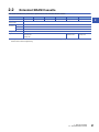
2.2
Extended SRAM Cassette
This section describes the performance specifications of the extended SRAM cassette.
Item
NZ2MC-1MBS
NZ2MC-2MBS
NZ2MC-4MBS
NZ2MC-8MBS
NZ2MC-16MBS
NZ2MC-8MBSE
Capacity
1M bytes
2M bytes
4M bytes
8M bytes
16M bytes
8M bytes
Number of insertions
and removals
Limited to 50 times
External
dimensions
Height
49mm
Width
32mm
Depth
18.5mm
Weight
Applicable CPU module
*1
2
20g
• Programmable controller CPU
• Process CPU
• Safety CPU
Programmable
controller CPU*1
• Process CPU
• Safety CPU
If using the devices with the RnCPU, check the versions of the CPU module and engineering tool used. ( MELSEC iQ-R CPU
Module User's Manual (Application))
2 SPECIFICATIONS
2.2 Extended SRAM Cassette
31
2.3
Safety Function Module
This section describes the specifications of the safety function module.
Hardware specifications
Item
R6SFM
Operation control method
Memory capacity
Safety program
40K steps (160K bytes)
Program memory
Safety program
160K bytes
Device/label memory
Safety program
80K bytes
Number of occupied I/O points
16 points*1
Buffer memory
4096K bytes
Allowable momentary power failure time
The time differs depending on the power supply module used. ( MELSEC
iQ-R Module Configuration Manual)
Internal current consumption (5VDC)
0.67A
External dimensions
Height
106mm (Base unit mounting side: 98mm)
Width
27.8mm
Depth
110mm
Weight
*1
32
Stored program cyclic operation
Program capacity
0.16kg
All I/O signals (input (X): 16 points, output (Y): 16 points) are use prohibited.
2 SPECIFICATIONS
2.3 Safety Function Module
3
FUNCTION LIST
The following table lists the functions of the CPU module.
Numbers in the Availability column indicate the CPU modules:
(1): RnCPU, (2): RnENCPU, (3): Process CPU, (4): Safety CPU
: Available, : Available with restrictions, : Not available
For details on the functions, refer to the following.
3
MELSEC iQ-R CPU Module User's Manual (Application)
Function
Description
Availability
(1)
(2)
(3)
(4)
Scan monitoring function
Detects a hardware failure or program error by monitoring that the
END processing is performed within a set scan time.
Clock function
Manages time for the system functions such as time stamps for
the event history function and date information for the data logging
function.
Online change (ladder block)
Writes the part of a program edited on the ladder editor using the
engineering tool to the running CPU module in units of ladder
blocks. Edited contents spanning multiple files or multiple portions
can be written to the CPU module at once.
Online change (files)
Writes programs and other data to the running CPU module in
units of files.
Multiple interrupt function
When an interrupt occurs while an interrupt program triggered by
another cause is running, stops the program if its priority is lower
than that of the new interrupt, and runs the higher-priority program
whenever its execution condition is satisfied.
PID control function
Performs PID control by using PID control instructions.
There are two kinds of PID control instructions: exact differential
form instructions and inexact differential form instructions.
Process control function
Performs various types of process control by using process control
instructions, such as two-degree-of-freedom PID control, sample
PI, and auto tuning, in combination.
Constant scan
Repeatedly runs a program while retaining the scan time constant.
Database function
Manages tabular data such as product information or production
information as a database on the programmable controller, and
accesses the database using the database access instructions.
Remote operation
Remotely controls the operating status of the CPU module,
keeping the position of the RUN/STOP/RESET switch at RUN.
Device/label memory area setting
Sets the capacity of each area in the device/label memory.
Internal buffer capacity setting
Sets the capacity of the area (internal buffer) used by the system
to temporarily store the results of data logging and memory dump
processing.
Initial device/label value setting
Sets the initial values of devices and labels used in the program
directly (not via the program) to the devices, labels, and buffer
memory areas of intelligent function modules.
Output mode setting when the status changed from
STOP to RUN
Sets the output (Y) status when the operating status of the CPU
module is switched from STOP to RUN.
Label access setting from external device
Enables communications specifying the global label name from
the GOT and external devices using SLMP.
Routing setting
Sets the communication path required for transient communication
to the stations on the different network.
Online change
Interrupt function
Holds the device/label data even at power-off.
SD memory card forced
disable
Forcibly disables an access to the SD memory card without
powering off the system even when the function that accesses the
SD memory card is being executed.
Boot operation
Transfers files in the SD memory card to the built-in memory of the
CPU module when the CPU module is powered off and on or
reset.
Sets the time or execution timing of the device/label access
service processing performed in the END processing in parameter.
Latch function
Memory card
function
Device/label access service processing setting
3 FUNCTION LIST
33
Function
Availability
(1)
(2)
(3)
(4)
Data logging function
Collects data at the specified interval or any desired timing, and
stores them as a file on the SD memory card.
Memory dump function
Saves the data in the devices of the CPU module at a desired
timing.
Real-time monitor function
Monitors the data in the specified device of the CPU module at a
specified interval or at a desired timing in real time.
RAS function
Self-diagnostics function
Self-diagnoses the CPU module to see whether an error exist or
not.
Error clear
Batch-clears all the continuation errors being detected.
Event history function
Collects operations executed and errors detected from the
modules, and saves them in the CPU module. The saved logs can
be checked in chronological order.
Online module change
Replaces a module without stopping the system. ( MELSEC
iQ-R Module Configuration Manual)
Program cache memory auto
recovery function
Automatically detects and recovers the data stored in the program
cache memory of the CPU module at the time of program
execution if the data is overwritten due to the factors such as
excessive electrical noise.
Device/buffer memory batch
monitor
Monitors values in devices and buffer memory using the
engineering tool connected.
Program monitor list
Monitors the execution time of each program and the number of
executions using the engineering tool connected.
Interrupt program monitor list
Monitors the number of executions of interrupt programs using the
engineering tool connected.
Out-of-group I/O fetch
Enables loading the input and output data of non-controlled
modules.
Multiple CPU synchronized
startup
Synchronizes the startup of CPU modules in a multiple CPU
system so that operations of all the CPU modules start at the
unified time.
Data communications
between CPU modules
Communicates data between CPU modules in a multiple CPU
system.
Multiple CPU synchronous
interrupt
Executes an interrupt program at the fixed communication timing
set in parameter.
Safety operation mode
There are two Safety CPU modes: TEST MODE and SAFETY
MODE. One mode is for changing the safety program or safety
parameters, and the other is for operating the system as a safety
system.
Continuous RUN prevention in TEST MODE
Starts the measurement of RUN time when the Safety CPU enters
the RUN state in TEST MODE, and generates a continuation error
when the continuous RUN time has exceeded the allowed time.
Safety diagnostic function
Self-diagnostic function of the Safety CPU
Safety data identify check
Checks if the project data created using the engineering tool and
the data in the Safety CPU are the same, and confirms that the
program executed in SAFETY MODE is the one written by the
user.
Safety communication function
Communicates data between the Safety CPU and modules
supporting safety functions using safety protocols.
SLMP communication function
Enables accesses to devices/labels and remote operations from
external devices other than the engineering tool by sending
request messages using SLMP. ( SLMP Reference Manual)
Security function
User authentication function
Limits access to the project in the personal computer by setting a
user name and password.
Block password function
Prevents unauthorized access to programs (in units of POUs).
Security key authentication
function
Prevents unauthorized access to programs (in units of program
files) or unauthorized execution of programs.
File password function
Prevents unauthorized reading/writing of data from/to files.
IP filter function
Identifies the IP address of external devices over Ethernet, and
blocks access from an invalid IP address.
Remote password function
Limits access from external devices to the CPU module to the
specific communication route via Ethernet.
Monitor function
Multiple CPU
system function
34
Description
3 FUNCTION LIST
Function
Description
Availability
(1)
(2)
(3)
(4)
Inter-module synchronization function
Controls multiple modules synchronously. ( MELSEC iQ-R
Inter-Module Synchronization Function Reference Manual)
Ethernet function
Accesses the CPU module over Ethernet.
Using this function, the CPU module can connect to MELSOFT
products and GOTs, perform socket communications, and transfer
FTP files. ( MELSEC iQ-R Ethernet User's Manual
(Application))
3
3 FUNCTION LIST
35
4
PROCEDURES BEFORE OPERATION
This chapter describes the procedures before operation.
Unless otherwise specified, windows of the engineering tool used for explanation in this chapter are those of
the project using the RnCPU. If the CPU module other than the RnCPU is used, windows actually displayed
may be different from those in this manual.
4.1
Overview
This section describes an outline of the procedure before operation for each CPU module.
Programmable controller CPU, Process CPU
Take the following procedure.
1.
Installing a battery
Install a battery to the CPU module. ( Page 38 Installing a Battery)
2.
Inserting an extended SRAM cassette and an SD memory card
Insert an extended SRAM cassette or an SD memory card or both to the CPU module as needed. ( Page 39 Inserting or
Removing an Extended SRAM Cassette, Page 40 Inserting and Removing an SD Memory Card)
3.
Mounting modules and connecting cables
Mount modules on the base unit, and connect cables. ( MELSEC iQ-R Module Configuration Manual)
4.
Powering on the system
Check the following items, and then power on the system.
• A cable is correctly connected to the power supply.
• Power supply voltage is within the specified range.
• The CPU module is in the STOP state.
5.
Connecting a personal computer
Connect a personal computer where an engineering tool has been installed to the CPU module. ( Page 41 Connecting a
Personal Computer)
6.
Initializing the CPU module
Initialize the CPU module using the engineering tool. ( Page 42 Initializing the CPU Module)
7.
Setting parameters
Set system parameters, CPU parameters, and module parameters. ( Page 42 Setting Parameters)
Parameters other than above need to be set to use the built-in Ethernet function of the CPU module, to execute functions
accessing the SD memory card, or when any intelligent function module is mounted. ( User's Manual (Application) for the
module used)
When the RnENCPU is used, set network parameters to the network part as well. ( User's Manual (Application) for the
network used)
System parameters are automatically set by loading an actual system configuration to the Module Configuration window of
the engineering tool.
8.
Programming
Create a program using the engineering tool. ( Page 45 Programming)
9.
Writing data to the programmable controller
Write the parameters set and the program created by using the engineering tool to the programmable controller. ( Page
49 Writing Data to the Programmable Controller)
36
4 PROCEDURES BEFORE OPERATION
4.1 Overview
10. Resetting the CPU module
Restart the system in either of the following ways.
• Power off and on the system.
• Reset the CPU module. (Page 50 Resetting the CPU Module)
11. Checking for errors
Check the status of the READY LED and ERROR LED of the CPU module. If an error is detected, identify the error using the
engineering tool, and eliminate the error cause. ( Page 53 Troubleshooting)
12. Executing the program
Run the CPU module, and check that the PROGRAM RUN LED turns on. ( Page 50 Executing the Program)
13. Monitoring the program
4
Check that the program operates normally using the engineering tool. ( Page 51 Monitoring the program)
Safety CPU
Take the following procedure.
1.
Installing a battery
Install a battery to the CPU module. ( Page 38 Installing a Battery)
2.
Inserting an extended SRAM cassette and an SD memory card
Insert an extended SRAM cassette or an SD memory card or both to the CPU module as needed. ( Page 39 Inserting or
Removing an Extended SRAM Cassette, Page 40 Inserting and Removing an SD Memory Card)
3.
Mounting modules and connecting cables
Mount modules on the base unit, and connect cables.
Mount the safety function module on the right of the Safety CPU. The Safety CPU and the safety function module must be the
same version. ( MELSEC iQ-R Module Configuration Manual)
4.
Powering on the system
Check the following items, and then power on the system.
• A cable is correctly connected to the power supply.
• Power supply voltage is within the specified range.
• The CPU module is in the STOP state.
5.
Connecting a personal computer
Connect a personal computer where an engineering tool has been installed to the CPU module. ( Page 41 Connecting a
Personal Computer)
6.
Registering user information (user authentication function)
Register a user name and password used to log in to the project. Then, write the user information to the Safety CPU. ( GX
Works3 Operating Manual)
7.
Initializing the CPU module
Initialize the CPU module using the engineering tool. ( Page 42 Initializing the CPU Module)
8.
Setting parameters
Set system parameters, CPU parameters, safety CPU parameters, module parameters, and safety module parameters. (
Page 42 Setting Parameters)
9.
Programming
Create a standard program or safety program using the engineering tool. ( Page 45 Programming)
10. Writing data to the programmable controller
Write the parameters set and programs (standard programs and safety programs) created using the engineering tool to the
Safety CPU. ( Page 49 Writing Data to the Programmable Controller)
When the data is written to the Safety CPU, the safety CPU parameters, safety module parameters, and safety programs are
also written to the safety function module.
4 PROCEDURES BEFORE OPERATION
4.1 Overview
37
11. Resetting the CPU module
Restart the system in either of the following ways.
• Power off and on the system.
• Reset the CPU module. (Page 50 Resetting the CPU Module)
12. Checking for errors
Check the status of the READY LED and ERROR LED of the Safety CPU and safety function module. If an error is detected,
identify the error using the engineering tool, and eliminate the error cause.
13. Executing the program
Run the CPU module, and check that the PROGRAM RUN LED turns on. ( Page 50 Executing the Program)
14. Switching TEST MODE to SAFETY MODE
Switch the safety operation mode from TEST MODE to SAFETY MODE using the engineering tool. ( MELSEC iQ-R CPU
Module User's Manual (Application))
The engineering tool switches the safety operation mode to SAFETY MODE (wait-for-restart). Power on or reset the CPU
module to switch the mode to SAFETY MODE.
15. Checking the LED status
Check the following LED status and check that the modules are operating normally.
• The PROGRAM RUN LED of the Safety CPU is on.
• The PROGRAM RUN LED and SAFETY COM RUN LED of the safety function module are on.
• The SAFETY COM ERROR LED and TEST LED of the safety function module are off.
16. Monitoring the program
Check that the program operates normally using the engineering tool. ( Page 51 Monitoring the program)
To change the programs and parameters during system operation, switch the safety operation mode from
SAFETY MODE to TEST MODE. ( MELSEC iQ-R CPU Module User's Manual (Application))
4.2
Installing a Battery
Install a battery to the CPU module.
Installation procedure
The connector plug of the Q6BAT is disconnected from the jack of the CPU module before shipment. To use the battery,
connect the connector, following the procedure below.
1.
(2)
module.
(1)
2.
3.
4.
4 PROCEDURES BEFORE OPERATION
4.2 Installing a Battery
Check that the Q6BAT (1) is correctly installed.
Check the direction and securely insert the connector plug of the
Q6BAT (2) to the jack (3) of the CPU module.
(3)
38
Open the battery cover located on the bottom of the CPU
Close the battery cover.
4.3
Inserting or Removing an Extended SRAM
Cassette
Insert an extended SRAM cassette to the CPU module as needed.
Insertion procedure
Insert an extended SRAM cassette while the programmable controller is powered off.
1. Open the cassette cover (1) located on the side of the
(1)
CPU module.
2.
Hold the top and bottom of the tab (2) of an extended
4
SRAM cassette (with the notched edge facing to the
right), and insert the cassette straight into the
(2)
connector. After inserting the cassette, check that it is
3.
4.
5.
inserted completely.
Close the cover, and mount the CPU module on the
base unit.
Power on the programmable controller.
Set the capacity of the inserted cassette in the CPU
parameters ("Extended SRAM Cassette Setting")
using the engineering tool.
[CPU Parameter] [Memory/Device Setting]
[Device/Label Memory Area Setting] [Extended
SRAM Cassette Setting]
6.
Using the engineering tool, check that SM626
(Extended SRAM cassette insertion flag) is on.
Precautions
• When the extended SRAM cassette is removed, all of the data on the device/label memory are erased. Back up the
program and data before replacing the cassette.
• If the capacity of the extended SRAM cassette differs before and after the replacement, the ERROR LED of the CPU
module may flash. But, it is not an error. Change the capacity setting in the CPU parameters. (Refer to step 5 above.)
• The extended SRAM cassette for the Universal model QCPU (Q4MCA-MBS) cannot be used.
• The programmable controller CPU does not support the use of NZ2MC-MBSE.
Removal procedure
Remove the extended SRAM cassette while the programmable controller is powered off.
1.
Read the data on the device/label memory from the CPU module, and save it in advance using the engineering tool.
(When the extended SRAM cassette is removed, all of the data on the device/label memory are erased.)
2.
3.
4.
5.
6.
7.
Power off the programmable controller.
Remove the CPU module from the base unit, and open the cassette cover located on the side of the CPU module.
Hold the top and bottom of the tab of the extended SRAM cassette, and pull the cassette straight out of the connector.
Close the cover, and mount the CPU module back on the base unit.
Power on the programmable controller.
Set the "Extended SRAM Cassette Setting" in the CPU parameters to "Not Mounted".
4 PROCEDURES BEFORE OPERATION
4.3 Inserting or Removing an Extended SRAM Cassette
39
4.4
Inserting and Removing an SD Memory Card
Insert an SD memory card to the CPU module as needed.
Insertion procedure
Check the direction and insert an SD memory card, following the procedure below.
1. Insert an SD memory card (1) into the card slot until it clicks with
the notched edge in the direction as illustrated. After inserting the
cassette, check that it is inserted completely. Poor contact may
(1)
cause malfunction.
2.
(2)
The CARD READY LED (2) starts flashing. When the card is
ready to be used, the CARD READY LED stops flashing and
turns on.
3.
If the CARD READY LED does not turn on even after the card is
inserted, check that SM606 (SD memory card forced disable
instruction) and SM607 (SD memory card forced disable status
flag) are off.
Removal procedure
1.
Press the SD memory card access control switch (1) for one
second or longer to disable access to the card.
2.
(3)
The CARD READY LED (2) flashes during the access stop
processing, and turns off upon completion of the processing.
(2)
3.
Push in and release the SD memory card (3), and then pull the
card out of the slot.
(1)
Precautions
• Follow the procedure above when inserting or removing the SD memory card while the system is powered on. If not, the
data on the SD memory card may corrupt.
• If any function that accesses the SD memory card is being executed when the SD memory card access control switch is
pressed to remove the card, the CARD READY LED turns off after the processing of the function is completed. For this
reason, the time required until the LED turns off differs depending on the function being executed.
• If SM605 (Memory card remove/insert prohibit flag) is on, the CARD READY LED does not turn off even if the SD memory
card access control switch is pressed. If not, turn on SM606 (SD memory card forced disable instruction) to forcibly disable
access to the card.
40
4 PROCEDURES BEFORE OPERATION
4.4 Inserting and Removing an SD Memory Card
4.5
Creating a Project
Activate the engineering tool and create a project.
[Project] [New]
Procedure
Create a program, following the procedure below. The procedure is for the program described in ladder diagrams.
1. Select the model of the CPU module used. Then, specify a
programming language used for the project. Select "Ladder", and
click the [OK] button.
4
2.
Click the [Yes] button when the window for adding module labels
of the CPU module appears.
Module label is a label where the I/O signals and buffer memory areas of a module have already been
defined. Use of module labels allows programming without being aware of module internal addresses.
4.6
Connecting a Personal Computer
Connect a personal computer where an engineering tool has been installed to the CPU module.
Procedure
Connect a personal computer directly to the CPU module, following the procedure below.
1. Connect a personal computer to the CPU module using a USB
CPU module
cable or Ethernet cable.
Personal computer
2.
3.
Select [Online] [Specify Connection Destination] on the menu
bar of the engineering tool.
Click the [CPU Module Direct Coupled Setting] button (1) on the
"Specify Connection Destination Connection" window.
(1)
(2)
4.
Select the connection method, and click the [Yes] button.
5.
Click the [Connection Test] button (2), and check if the personal
computer is connected to the CPU module.
Install a USB driver to use a USB cable for the first time. ( GX Works3 Operating Manual)
4 PROCEDURES BEFORE OPERATION
4.5 Creating a Project
41
4.7
Initializing the CPU Module
Initialize the CPU module.
[Online] [CPU Memory Operation]
Procedure
1.
Select "Data Memory" on the "Memory Management" window,
and click the [Initialization] button.
2.
3.
Select "File Storage Area", and click the [Initialization] button.
After the initialization processing completes, click the [Close]
button.
4.8
Setting Parameters
Set system parameters and parameters for each module.
When the engineering tool is connected to the actual system
Set parameters by loading an actual system configuration to the Module Configuration window of the engineering tool.
"Navigation window" "Module Configuration"
1.
Open the Module Configuration window, and select [Online]
[Read Module Configuration from PLC] on the menu bar.
2.
3.
Click the [Yes] button when the window for adding module labels
of the mounted modules appears.
The system parameters are automatically set, and the actual
system configuration is displayed on the Module Configuration
window.
4.
Double-click each module (CPU module, I/O module, or
intelligent function module) to display the corresponding module
parameter editor.
5.
Set parameters, and click the [Apply] button to close the window.
■Precautions
The RQ extension base units, MELSEC-Q series extension base units, and modules mounted on those base units cannot be
loaded. For those cannot be loaded, select the units and modules on the Element Selection window, and drag and drop them
to the system configured on the Module Configuration window.
42
4 PROCEDURES BEFORE OPERATION
4.7 Initializing the CPU Module
When the engineering tool is not connected to the actual system
Set parameters by configuring a system manually on the Module Configuration window of the engineering tool.
1. Select a base unit on the Element Selection window, and drag
and drop it to the Module Configuration window.
2.
Drag and drop modules to be used on the base unit placed.
4
3.
4.
Select [Edit] [Parameter] [Fix] on the menu bar.
Click the [Yes] button when the window for adding module labels
of the configured modules appears.
5.
Open the parameter editor of each module by double-clicking the
module.
6.
Set parameters, and click the [Apply] button to close the window.
To use the RnENCPU, the modules can be found from different categories. Select each module from the
following categories on the Element Selection window.
• RnENCPU (CPU part): "PLC CPU"
• RnENCPU (network part): "CPU Extension"
4 PROCEDURES BEFORE OPERATION
4.8 Setting Parameters
43
Setting parameters from the Navigation window
Set the following parameters from the Navigation window.
■System parameters
These parameters need to be set from the Navigation window in the following cases: to change the number of slots on the
base unit or the number of occupied points of the module; for a multiple CPU system; and for module synchronization
operations.
"Navigation window" "Parameter" "System Parameter"
■Module parameters of the CPU module
These parameters are required to execute the built-in Ethernet function of the CPU module.
"Navigation window" "Parameter" (CPU module) "Module Parameter"
■Memory card parameters
These parameters are required to execute functions that access the SD memory card.
"Navigation window" "Parameter" (CPU module) "Memory Card Parameter"
■Multiple module parameters and module extension parameters
Some intelligent function modules require multiple module parameters and module extension parameters.
"Navigation window" "Parameter" "Module Information" (intelligent function module) "Module Parameter" or
"Module Extended Parameter"
System parameters can be set on the following windows. Select the window depending on their application
purposes.
• Module Configuration window: Use this window when using the module specific data (such as number of
occupied points) as is.
• System Parameter window: Use this window when changing the number of slots or the number of occupied
points.
44
4 PROCEDURES BEFORE OPERATION
4.8 Setting Parameters
4.9
Programming
Create a program. This section describes how to create a program using the following program example.
Program example
• When Start1 turns on, Timer1 starts counting, and Lamp1 turns on.
4
• When the current value of Timer1 reaches 1000, Lamp1 turns off.
• When Stop1 turns on, Lamp1 turns off.
Registering labels
Label is a variable whose name and data type can be declared by a user.
Use of labels allows programming without being aware of devices and buffer memory addresses. For this reason, programs
using labels can be used in other systems where the module configuration is different.
Labels can be registered on the label editor.
"Navigation window" "Program" "Scan" "MAIN" "ProgPou" "Local Label"
Procedure
Register the label "Start1" in the program example, following the procedure below.
1. Enter the name, "Start1", in the "Label Name" field (1).
2.
Click the button (2) on the right of the "Data Type" field to open
the "Data Type Selection" window.
(1)
(2)
3.
Specify the data type. Select "Bit", and click the [OK] button.
Register other labels in the program example in the same way.
• The class, initial value, and constant of labels can be set as needed by clicking the [Show Details] button on
the label editor.
• Labels can also be registered while programming without opening the label editor. ( Page 48 Inserting
POUs by key input)
• Devices can be assigned to global labels. Open the global label editor, and enter a device in the "Assign
(Device/Label)" field.
4 PROCEDURES BEFORE OPERATION
4.9 Programming
45
Inserting program elements
Drag and drop required program elements to the ladder editor.
"Navigation window" "Program" "Scan" "MAIN" "ProgPou" "Program"
Procedure
Insert a normally open contact of "Start1" in the program example, following the procedure below.
1. Select a program element from the Element Selection window,
and drag and drop (1) it to the desired position on the ladder
editor. In this example, drag and drop "LD[1]".
(1)
2.
Double-click the inserted program element, and click the [Extd
Dspl] button to open the ladder entry window.
3.
Specify the operand. In this example, enter "Start" for "s" in the
"Device/Label" field.
4.
Select an item from the displayed list (3). In this example, select
"Start1".
(2)
(3)
5.
The normally open contact of "Start1" is inserted to the program.
Insert other program elements in the program example in the same way.
• Common instructions, such as contacts and coils, standard functions/function blocks, and user-defined
function blocks/functions can be found in the [POU List] (1) in the Element Selection window. Narrow the list
using the drop-down menu (2) for "Display Target", and select program elements.
• Module labels and module function blocks can be found in the [Module] list (3). Programs are efficiently
created only by dragging and dropping the module labels and module function blocks on the editor.
(2)
(1)
46
4 PROCEDURES BEFORE OPERATION
4.9 Programming
(3)
■Inserting function blocks
Insert function blocks, following the procedure below.
1.
Select a function block from the Element Selection window, and
drag and drop it to the desired position on the ladder editor.
2.
The "FB Instance Name" window opens. Select the target label
4
(global label or local label), and enter an instance name.
3.
Select [Convert] [Convert] on the menu bar. The ladder is
converted, and the rungs are connected to the input and output
labels of the FB instance.
4.
Add the input and output parts of the inserted function block to
complete the program. For details on the input and output parts,
refer to the following.
Function Block Reference for the module used
■Creating function blocks/functions
User-defined function blocks/functions must be created before inserted to the program.
1. Right-click "FB/FUN" (1) on the Navigation window, and select
"Add New Data" (2) to open the setting window.
(1)
(2)
2.
To create a function block, set the data type to "Function Block"
using the drop-down list. To create a function, set the data type to
"Function". Then, click the [OK] button.
3.
Create the processing of the function block or function on the
"Program" window.
4 PROCEDURES BEFORE OPERATION
4.9 Programming
47
Inserting POUs by key input
POUs can be inserted by key input.
Procedure
Inserting a normally open contact of "Start1" in the program example, following the procedure below.
1. Click the insertion position on the ladder editor, and press .
2.
Enter the name, "Start1", in the entry field (1). Select "Start1"
from the displayed list (2).
(1)
(2)
3.
The normally open contact of "Start1" is inserted to the program.
A new label can be registered during insertion. Enter the name of a new label on the ladder entry window, and
click the [OK] button. Then, specify the registered destination, class, and data type of the label on the
"Undefined Label Registration" window, and click the [OK] button.
48
4 PROCEDURES BEFORE OPERATION
4.9 Programming
4.10
Converting the Program
Determine the input ladder blocks.
Procedure
1.
2.
Select [Convert] [Convert] on the menu bar.
When the conversion processing completes and the input ladder blocks are determined, the color of those ladder blocks
changes from gray to white.
4.11
Saving the Project
4
Save the created project.
[Project] [Save as]
4.12
Writing Data to the Programmable Controller
Write the set parameters and the created program to the programmable controller.
[Online] [Write to PLC]
Procedure
1.
Select the system parameter file, CPU parameter file, module
parameter file, and program file on the "Online Data Operation"
window. If any function block is used, select the corresponding
FB/FUN file as well.
2.
3.
Click the [Execute] button.
After the write processing completes, click the [Close] button.
• For the operation of the CPU module, the system parameter file, CPU parameter file, and program file must
be written. For the operation of the I/O modules and intelligent function modules, the module parameter files
and module extension parameter file must be written as well.
• When a parameter setting is changed, reset the CPU module. (Page 50 Resetting the CPU Module)
• Use of the [Select Favorites] button enables users to easily select frequently-used files, such as the system
parameter file, CPU parameter file, and program file. Register items as favorites on the window opened by
selecting [Setting] [Register Favorites Selection] on the menu bar.
4 PROCEDURES BEFORE OPERATION
4.10 Converting the Program
49
4.13
Resetting the CPU Module
Reset the CPU module using the RUN/STOP/RESET switch located on the front of the CPU module.
Procedure
1.
Set the RUN/STOP/RESET switch (1) to the RESET position for
a second or longer.
(2)
2.
Check that the ERROR LED (2) flashes for several times and
turns off.
3.
Set the switch back to the STOP position.
(1)
Operate the RUN/STOP/RESET switch with your fingers. Use of a tool such as a screwdriver may damage
the switch.
4.14
Executing the Program
Execute the program written to the programmable controller by using the RUN/STOP/RESET switch.
Procedure
1.
2.
(2)
(1)
50
4 PROCEDURES BEFORE OPERATION
4.13 Resetting the CPU Module
Set the RUN/STOP/RESET switch (1) to the RUN position.
Check that the PROGRAM RUN LED (P RUN) (2) turns on.
4.15
Monitoring the program
Monitor the program operation using the engineering tool.
Monitoring on the monitor status bar
The LED status of the CPU module and the scan time can be monitored on the monitor status bar.
(5)
(6)
4
(4)
(3)
(2)
(1)
1.
2.
Select [Online] [Monitor] [Start Monitoring] on the menu bar.
Monitor the LED status of the CPU module and the scan time.
■Displayed item
No.
Item
Description
(1)
Connection status
The connection status with the CPU module is displayed.
Icon
Meaning
Connected with the CPU
module
Not connected with the
CPU module
(2)
(3)
(4)
Operating status
ERROR LED status
USER LED status
The operating status of the CPU module in accordance with the RUN/
STOP/RESET switch of the CPU module or the remote operation by
the engineering tool is displayed.
RUN
The ERROR LED status of the CPU module is displayed.
The "Module Diagnostics" window opens by clicking the icon.
( Page 55 Module diagnostics)
Off
The USER LED status of the CPU module is displayed.
The "Module Diagnostics" window opens by clicking the icon.
( Page 55 Module diagnostics)
Off
STOP
PAUSE
On
Flashing
On
Flashing
(5)
Scan time details
The scan time details are displayed. Select the value to be displayed from the drop-down list (current value, maximum value,
or minimum value).
(6)
Monitor target
selection
Specify the monitor target FB instance when monitoring a FB program.
4 PROCEDURES BEFORE OPERATION
4.15 Monitoring the program
51
Monitoring on the ladder editor
The on/off states of contacts and coils and the current values of word devices and labels can be monitored on the ladder
editor.
(1)
(1)
1.
2.
(1) The on/off states of
the contacts and coils are
displayed.
(2) The current value of
the word/double word
type data is displayed.
(2)
Select [Online] [Monitor] [Start Monitoring] on the menu bar.
Monitor the on/off states of contacts and coils and the current values of word devices and labels.
■On/off state display
The on/off states are displayed on the editor as follows:
■Changing the current value
To change the current value, select the cell on the ladder editor, and press + double-click the cell or press +
while the program is being monitored.
The program can also be monitored on the Device/Buffer Memory Batch window or the Watch window. (
GX Works3 Operating Manual)
52
4 PROCEDURES BEFORE OPERATION
4.15 Monitoring the program
4.16
Troubleshooting
This section describes errors that may occur during system operation, error causes, and actions to be taken.
For the troubleshooting specific to each module, refer to the manual for the module used.
Saving the program and devices at the time of an error helps to analyze the error cause. ( GX Works3
Operating Manual)
Troubleshooting procedure
4
When the system has any trouble, perform troubleshooting in the following order.
1.
Check the LED status of the power supply module.
( MELSEC iQ-R CPU Module User's Manual (Application))
2.
3.
Check the LED status of the CPU module. ( Page 54 LED status of the CPU module)
Check the LED status of each I/O module and intelligent function module. ( User's Manual (Application) for the
module used)
4.
Connect an engineering tool, and execute the system monitor function. The error module can be identified. ( Page
55 System monitor)
5.
Select the error module, and execute the module diagnostics function. The error cause and the action to be taken can be
displayed. ( Page 55 Module diagnostics)
6.
If the error cause cannot be identified by the module diagnostics, check the executed operations and detected error logs
on the event history window. ( Page 56 Event history)
7.
If the error cause cannot be identified in steps 1 to 6, perform troubleshooting by symptom. ( User's Manual
(Application) for the module used)
4 PROCEDURES BEFORE OPERATION
4.16 Troubleshooting
53
Troubleshooting with LED indicators
Check the LED status of each module as primary diagnostics.
LED status of the CPU module
The following table lists the check points on the LED status of the CPU module.
The error status can be checked visually using the READY LED and ERROR LED.
LED indicator
Error status
Program
execution
status
Description
Action
Off
No error
Continued
Normal operation
On
Minor error
A minor error or warning has been detected.
Program execution and data communications with
network stations are continued.
Identify the error cause using the engineering
tool, and take an action.
Flashing
Moderate error
A programming error, parameter setting error, or
temporal noise has been detected. Program
execution and data communications with network
stations are stopped.
Identify the error cause using the engineering
tool, and take an action.
On/
flashing
Major error
A hardware failure has been detected. No
operation cannot be performed.
Perform troubleshooting for the error module. If
the problem still exists after troubleshooting,
replace the error module. ( MELSEC iQ-R
CPU Module User's Manual (Application))
Off
Hardware
failure
A hardware failure has been detected. No
operation cannot be performed.
Check that the power is supplied to the system.
If the power is supplied properly, the possible
cause is a hardware failure. Perform
troubleshooting for the error module. If the
problem still exists after troubleshooting,
replace the error module. ( MELSEC iQ-R
CPU Module User's Manual (Application))
No error
Power is not supplied or power went out.
On
Minor error
A minor error has been detected during online
module change.
Identify the error cause using the engineering
tool, and take an action.
Off
No error
READY
ERROR
On
Off
Flashing
Stopped
• The READY LED is flashing every 400ms: A
module is being changed online.
• The READY LED is flashing every 2s: Initial
processing is being performed.
The LED status can also be checked on the module diagnostics window using the engineering tool. ( GX
Works3 Operating Manual)
Troubleshooting using the engineering tool
Check the error or history using the engineering tool, and identify the error cause. More detailed information on the error as
well as the error cause and action to be taken can be checked by using the engineering tool.
The engineering tool has the following functions for troubleshooting.
Function
Description
System monitor
Displays the module configuration, and detailed information and error status of each module. ( Page 55
System monitor)
Module diagnostics
Diagnoses the module. (The current error and its details can be checked.) ( Page 55 Module diagnostics)
Event history
Displays the event information collected by the CPU module, such as errors occurred in each module, executed
operations, and network errors. ( Page 56 Event history)
For details on each function, refer to the following.
GX Works3 Operating Manual
54
4 PROCEDURES BEFORE OPERATION
4.16 Troubleshooting
System monitor
This function displays the module configuration, and detailed information and error status of each module.
For the error module identified, the module diagnostics function can be executed from this window.
[Diagnostics] [System Monitor]
4
When the RnENCPU is used, information of the RnENCPU (CPU part) and RnENCPU (network part) is
displayed individually. When an error occurs, the module diagnostics function can be executed for each
module.
Module diagnostics
This function diagnoses the module. (The current error and its details can be checked.)
Information required for troubleshooting, such as the current error, details and cause of the error, and action to be taken, are
displayed. The incorrect parameter setting and program error location can also be identified by selecting the error and clicking
the [Error Jump] button.
On the [Module Information List] tab, the LED status and the switch status of the target module can be checked.
[Diagnostics] [System Monitor] Click the error module.
4 PROCEDURES BEFORE OPERATION
4.16 Troubleshooting
55
Event history
This function displays the event information, such as errors occurred in the module(s) mounted, executed operations, and
network errors.
Since information collected before the CPU module is powered off or reset can also be displayed, the error cause can be
identified based on the past operations and errors.
The displayed information can also be saved in CSV file format.
[Diagnostics] [System Monitor] [Event History] button
Use this function for the following purposes:
• To check the error status of all the modules in the system and identify the cause of error occurred in
machinery or equipment
• To check when and how the program and parameters of the programmable controller have been changed
• To check for unauthorized access
For details on this function and collected information, refer to the following.
MELSEC iQ-R CPU Module User's Manual (Application)
56
4 PROCEDURES BEFORE OPERATION
4.16 Troubleshooting
APPENDIX
Appendix 1
A
External Dimensions
CPU module
98
106
4
RnCPU, Process CPU, Safety CPU
27.8
110
27
154
(Unit: mm)
APPENDIX
Appendix 1 External Dimensions
57
(106)
30
4
98
4
• With the Q7BAT-SET
27.4
110
(Unit: mm)
58
APPENDIX
Appendix 1 External Dimensions
27.8
RnENCPU
98
106
4
A
56
110
26.5
152
(Unit: mm)
APPENDIX
Appendix 1 External Dimensions
59
(106)
30
4
98
4
• With the Q7BAT-SET
0.2
110
27.4
56
(Unit: mm)
98
106
4
Safety function module
110
(Unit: mm)
60
APPENDIX
Appendix 1 External Dimensions
27.8
MEMO
A
APPENDIX
Appendix 1 External Dimensions
61
INDEX
A
L
Annunciator (F) . . . . . . . . . . . . . . . . . . . . . . . 27,29
Label . . . . . . . . . . . . . . . . . . . . . . . . . . . . . . . . .45
Label area . . . . . . . . . . . . . . . . . . . . . . . . . . . . .24
Latch label area . . . . . . . . . . . . . . . . . . . . . . . . .24
Latch relay (L) . . . . . . . . . . . . . . . . . . . . . . . 27,29
Link direct device . . . . . . . . . . . . . . . . . . . . . . . . 28
Link register (W) . . . . . . . . . . . . . . . . . . . . . . 27,29
Link relay (B) . . . . . . . . . . . . . . . . . . . . . . . . 27,29
Link special register (SW) . . . . . . . . . . . . . . . 27,29
Link special relay (SB). . . . . . . . . . . . . . . . . . 27,29
Long counter (LC) . . . . . . . . . . . . . . . . . . . . . 27,29
Long index register (LZ) . . . . . . . . . . . . . . . . 28,30
Long retentive timer (LST) . . . . . . . . . . . . . . . 27,29
Long timer (LT). . . . . . . . . . . . . . . . . . . . . . . 27,29
B
Battery . . . . . . . . . . . . . . . . . . . . . . . . . . 19,21,38
BATTERY LED . . . . . . . . . . . . . . . . . . . . . . . 19,21
C
CARD ACCESS LED. . . . . . . . . . . .
CARD READY LED . . . . . . . . . . . . .
Constant scan . . . . . . . . . . . . . . . .
Counter (C) . . . . . . . . . . . . . . . . . .
CPU buffer memory . . . . . . . . . . . .
CPU buffer memory access device . .
CPU module . . . . . . . . . . . . . . . . . .
CPU parameter . . . . . . . . . . . . . . . .
. . . . . . . 19,21
. . . . 19,21,40
. . . . . . . 27,29
. . . . . . . 27,29
. . . . . . . 24,26
. . . . . . . . . 28
. . . . . . . 24,57
. . . . . . . . . 49
M
Memory capacity . . . . . . . . . . . . . . . . . . . 24,26,32
Module access device . . . . . . . . . . . . . . . . . . . . .28
Module extension parameter . . . . . . . . . . . . . . . .49
Module label . . . . . . . . . . . . . . . . . . . . . . . . . . . 41
Module parameter . . . . . . . . . . . . . . . . . . . . . . .49
Multiple CPU synchronous interrupt (I45) . . . . . . .27
D
Data memory . . . . . .
Data register (D) . . . .
Device area . . . . . . .
Device/label memory .
. . . . . . . . . . . . . . . . . . 24,26
. . . . . . . . . . . . . . . . . . 27,29
. . . . . . . . . . . . . . . . . . . . 24
. . . . . . . . . . . . . . . 24,26,32
N
Nesting (N) . . . . . . .
Number of FB files . .
Number of I/O points .
NZ2MC-16MBS . . . .
NZ2MC-1MBS . . . . .
NZ2MC-2MBS . . . . .
NZ2MC-4MBS . . . . .
NZ2MC-8MBS . . . . .
NZ2MC-8MBSE . . . .
E
Edge relay (V) . . . . . . . . . .
ERROR LED . . . . . . . . . . .
Ethernet port . . . . . . . . . . .
Extended SRAM cassette . .
External dimensions . . . . . .
. . . . . . . . . . . . . 27,29
. . . . . 19,21,50,51,54
. . . . . . . . 19,21,24,26
. . . . . . . . . . . . . 31,39
. . . . . 25,26,31,32,57
F
File register (R/ZR) . . . .
File storage area . . . . . .
Function block . . . . . . .
Function input (FX) . . . .
FUNCTION LED . . . . . .
Function output (FY) . . .
Function register (FD) . .
. . . . . . . . . . . . . . . . 28,30
. . . . . . . . . . . . . . . . . . 24
. . . . . . . . . . . . . . . . . . 47
. . . . . . . . . . . . . . . . 28,29
. . . . . . . . . . . . . . . . 19,21
. . . . . . . . . . . . . . . . 28,29
. . . . . . . . . . . . . . . . 28,29
O
Output (Y) . . . . . . . . . . . . . . . . . . . . . . . . . . 27,29
P
Parameter . . . . . . . . . . . . . . . . . .
Pointer (P) . . . . . . . . . . . . . . . . . .
Process CPU . . . . . . . . . . . . . . . .
Production information marking . . .
Program capacity . . . . . . . . . . . . .
Program file . . . . . . . . . . . . . . . . .
Program memory . . . . . . . . . . . . .
PROGRAM RUN LED . . . . . . . . . .
Programmable controller CPU . . . .
Programming language . . . . . . . . .
H
High-speed internal timer interrupt 1 (I49) . . . . . . 27
High-speed internal timer interrupt 2 (I48) . . . . . . 27
I
Index register (Z) . . . . . . . . . . . . . . . . . . . . . 28,30
Initializing the CPU module . . . . . . . . . . . . . . . . 42
Input (X) . . . . . . . . . . . . . . . . . . . . . . . . . . . . 27,29
Intelligent function module device . . . . . . . . . . . . 30
Inter-module synchronous interrupt (I44) . . . . . . . 27
Internal current consumption (5VDC) . . . . 24,26,32
Internal relay (M) . . . . . . . . . . . . . . . . . . . . . . 27,29
Interrupt pointer (I) . . . . . . . . . . . . . . . . . . . . 28,30
Interrupt using the internal timer (I28 to I31) . . . 27,29
62
. . . . . . . . . . . . . . . . . . . . .28
. . . . . . . . . . . . . . . . . . 27,29
. . . . . . . . . . . . . . . . . . . . .27
. . . . . . . . . . . . . . . . . . . . .31
. . . . . . . . . . . . . . . . . . . . .31
. . . . . . . . . . . . . . . . . . . . .31
. . . . . . . . . . . . . . . . . . . . .31
. . . . . . . . . . . . . . . . . . . . .31
. . . . . . . . . . . . . . . . . . . . .31
. . . . . . . . . . .42
. . . . . . . . 28,30
. . . . . . . . . . .15
. . . . . . . . 19,21
. . . . . . 24,26,32
. . . . . . . . . . . 49
. . . . . . 24,26,32
. . . . . .19,21,50
. . . . . . . . . . .15
. . . . . .27,29,41
Q
Q6BAT . . . . . . . . . . . . . . . . . . . . . . . . . . . . . . .38
R
READY LED . . . . . . . . . . . . . . . . . . . . . . 19,21,54
Refresh data register. . . . . . . . . . . . . . . . . . . . . .28
Refresh data register (RD) . .
Refresh memory . . . . . . . . .
Resetting the CPU module . .
Retentive timer (ST) . . . . . .
RnCPU . . . . . . . . . . . . . . .
RnENCPU . . . . . . . . . . . . .
RnENCPU (CPU part) . . . . .
RnENCPU (network part) . . .
RUN/STOP/RESET switch . .
. . . . . . . . . . . . . . . 30
. . . . . . . . . . . . . 24,26
. . . . . . . . . . . . . . . 50
. . . . . . . . . . . . . 27,29
. . . . . . . . . . . . . . . 15
. . . . . . . . . . . . . . . 15
. . . . . . . . . . . . . . . 15
. . . . . . . . . . . . . . . 15
. . . . . . . . 19,21,50,51
I
S
SAFETY COM ERR LED . . . . . . . . . . . . .
SAFETY COM RUN LED . . . . . . . . . . . . .
Safety communications . . . . . . . . . . . . . .
Safety control . . . . . . . . . . . . . . . . . . . . .
Safety counter . . . . . . . . . . . . . . . . . . . .
Safety CPU . . . . . . . . . . . . . . . . . . . . . .
Safety data register . . . . . . . . . . . . . . . . .
Safety device . . . . . . . . . . . . . . . . . . . . .
Safety function module . . . . . . . . . . . . . .
Safety input . . . . . . . . . . . . . . . . . . . . . .
Safety internal relay . . . . . . . . . . . . . . . .
Safety link register . . . . . . . . . . . . . . . . .
Safety link relay . . . . . . . . . . . . . . . . . . .
Safety output . . . . . . . . . . . . . . . . . . . . .
Safety program . . . . . . . . . . . . . . . . . . . .
Safety programmable controller . . . . . . . .
Safety retentive timer. . . . . . . . . . . . . . . .
Safety special register . . . . . . . . . . . . . . .
Safety special relay . . . . . . . . . . . . . . . . .
Safety system device. . . . . . . . . . . . . . . .
Safety timer . . . . . . . . . . . . . . . . . . . . . .
Safety user device . . . . . . . . . . . . . . . . .
SD memory card . . . . . . . . . . . . . . . . . . .
SD memory card access control switch . . .
SD/RD LED . . . . . . . . . . . . . . . . . . . . . .
SFC block device (BL) . . . . . . . . . . . . . . .
SFC transition device (TR) . . . . . . . . . . . .
Special register (SD) . . . . . . . . . . . . . . . .
Special relay (SM) . . . . . . . . . . . . . . . . . .
SPEED LED . . . . . . . . . . . . . . . . . . . . . .
Standard communications . . . . . . . . . . . .
Standard control . . . . . . . . . . . . . . . . . . .
Standard CPU . . . . . . . . . . . . . . . . . . . .
Standard device . . . . . . . . . . . . . . . . . . .
Standard program . . . . . . . . . . . . . . . . . .
Standard programmable controller . . . . . .
Step relay (S) . . . . . . . . . . . . . . . . . . . . .
System parameter . . . . . . . . . . . . . . . . . .
. . . . . 23
. . . . . 23
. . . . . 16
. . . . . 16
. . . . . 29
. . . . . 15
. . . . . 29
. . . . . 16
. . . . . 15
. . . . . 29
. . . . . 29
. . . . . 29
. . . . . 29
. . . . . 29
. . . . . 16
. . . . . 16
. . . . . 29
. . . . . 29
. . . . . 29
. . . . . 29
. . . . . 29
. . . . . 29
. . . 24,40
. . . 19,21
. . . 19,21
. . . . . 28
. . . . . 28
. . . 28,29
. . . 28,29
. . . 19,21
. . . . . 16
. . . . . 16
. . . . . 16
. . . . . 16
. . . . . 16
. . . . . 16
. . . . . 27
. . . . . 49
T
TEST LED . . . . . . . . . . . . . . . . . . . . . . . . . . . . 23
Timer (T) . . . . . . . . . . . . . . . . . . . . . . . . . . . 27,29
Troubleshooting . . . . . . . . . . . . . . . . . . . . . . . . 53
U
USB port . . . . . . . . . . . . . . . . . . . . . . 19,21,24,26
USER LED . . . . . . . . . . . . . . . . . . . . . . . 19,21,51
W
Weight . . . . . . . . . . . . . . . . . . . . . . . . 25,26,31,32
63
REVISIONS
*The manual number is given on the bottom left of the back cover.
Revision date
*Manual number
Description
June 2014
SH(NA)-081263ENG-A
First edition
October 2014
SH(NA)-081263ENG-B
■Added functions
Memory dump function, real-time monitor function, LED indication expansion
■Added or modified parts
SAFETY PRECAUTIONS, TERMS, Section 1.1, Chapter 3, Section 4.4, 4.5, 4.7, 4.8, 4.11
January 2015
SH(NA)-081263ENG-C
■Added models
R08PCPU, R16PCPU, R32PCPU, R120PCPU, NZ2MC-8MBSE
■Added functions
Process control function, online module change function
■Added or modified parts
INTRODUCTION, TERMS, Section 1.1, 2.1, 2.2, Chapter 3, Section 4.2, 4.8, 4.15, Appendix 1
August 2015
SH(NA)-081263ENG-D
■Added models
R04ENCPU, R08ENCPU, R08SFCPU, R16ENCPU, R16SFCPU, R32ENCPU, R32SFCPU,
R120ENCPU, R120SFCPU, NZ2MC-16MBS, R6SFM
■Added functions
User authentication function, safety function
■Added or modified parts
SAFETY PRECAUTIONS, CONDITIONS OF USE FOR THE PRODUCT, INTRODUCTION,
COMPLIANCE WITH MACHINERY DIRECTIVE, TERMS, Section 1.1, 1.3, 2.1, 2.2, 2.3, Chapter 3,
Section 4.1, 4.3, 4.8, 4.16, Appendix 1, WARRANTY
Japanese manual number SH-081223-D
This manual confers no industrial property rights of any other kind, nor does it confer any patent licenses. Mitsubishi Electric Corporation cannot be held
responsible for any problems involving industrial property rights which may occur as a result of using the contents noted in this manual.
2014 MITSUBISHI ELECTRIC CORPORATION
64
WARRANTY
Please confirm the following product warranty details before using this product.
1. Gratis Warranty Term and Gratis Warranty Range
If any faults or defects (hereinafter "Failure") found to be the responsibility of Mitsubishi occurs during use of the product
within the gratis warranty term, the product shall be repaired at no cost via the sales representative or Mitsubishi Service
Company.
However, if repairs are required onsite at domestic or overseas location, expenses to send an engineer will be solely at
the customer's discretion. Mitsubishi shall not be held responsible for any re-commissioning, maintenance, or testing
on-site that involves replacement of the failed module.
[Gratis Warranty Term]
The gratis warranty term of the product shall be for one year after the date of purchase or delivery to a designated place.
Note that after manufacture and shipment from Mitsubishi, the maximum distribution period shall be six (6) months, and
the longest gratis warranty term after manufacturing shall be eighteen (18) months. The gratis warranty term of repair
parts shall not exceed the gratis warranty term before repairs.
[Gratis Warranty Range]
(1) The range shall be limited to normal use within the usage state, usage methods and usage environment, etc., which
follow the conditions and precautions, etc., given in the instruction manual, user's manual and caution labels on the
product.
(2) Even within the gratis warranty term, repairs shall be charged for in the following cases.
1. Failure occurring from inappropriate storage or handling, carelessness or negligence by the user. Failure caused
by the user's hardware or software design.
2. Failure caused by unapproved modifications, etc., to the product by the user.
3. When the Mitsubishi product is assembled into a user's device, Failure that could have been avoided if functions
or structures, judged as necessary in the legal safety measures the user's device is subject to or as necessary by
industry standards, had been provided.
4. Failure that could have been avoided if consumable parts (battery, backlight, fuse, etc.) designated in the
instruction manual had been correctly serviced or replaced.
5. Failure caused by external irresistible forces such as fires or abnormal voltages, and Failure caused by force
majeure such as earthquakes, lightning, wind and water damage.
6. Failure caused by reasons unpredictable by scientific technology standards at time of shipment from Mitsubishi.
7. Any other failure found not to be the responsibility of Mitsubishi or that admitted not to be so by the user.
2. Onerous repair term after discontinuation of production
(1) Mitsubishi shall accept onerous product repairs for seven (7) years after production of the product is discontinued.
Discontinuation of production shall be notified with Mitsubishi Technical Bulletins, etc.
(2) Product supply (including repair parts) is not available after production is discontinued.
3. Overseas service
Overseas, repairs shall be accepted by Mitsubishi's local overseas FA Center. Note that the repair conditions at each FA
Center may differ.
4. Exclusion of loss in opportunity and secondary loss from warranty liability
Regardless of the gratis warranty term, Mitsubishi shall not be liable for compensation of damages caused by any cause
found not to be the responsibility of Mitsubishi, loss in opportunity, lost profits incurred to the user by Failures of
Mitsubishi products, special damages and secondary damages whether foreseeable or not, compensation for accidents,
and compensation for damages to products other than Mitsubishi products, replacement by the user, maintenance of
on-site equipment, start-up test run and other tasks.
5. Changes in product specifications
The specifications given in the catalogs, manuals or technical documents are subject to change without prior notice.
65
For Safety CPUs
Please confirm the following product warranty details before using this product.
1. Limited Warranty and Product Support.
a. Mitsubishi Electric Company ("MELCO") warrants that for a period of eighteen (18) months after date of delivery from the point of
manufacture or one year from date of Customer's purchase, whichever is less, Mitsubishi MELSEC Safety programmable logic
controllers (the "Products") will be free from defects in material and workmanship.
b. At MELCO's option, for those Products MELCO determines are not as warranted, MELCO shall either repair or replace them or issue
a credit or return the purchase price paid for them.
c. For this warranty to apply:
(1) Customer shall give MELCO (i) notice of a warranty claim to MELCO and the authorized dealer or distributor from whom the
Products were purchased, (ii) the notice shall describe in reasonable details the warranty problem, (iii) the notice shall be
provided promptly and in no event later than thirty (30) days after the Customer knows or has reason to believe that Products are
not as warranted, and (iv) in any event, the notice must given within the warranty period;
(2) Customer shall cooperate with MELCO and MELCO's representatives in MELCO's investigation of the warranty claim, including
preserving evidence of the claim and its causes, meaningfully responding to MELCO's questions and investigation of the
problem, grant MELCO access to witnesses, personnel, documents, physical evidence and records concerning the warranty
problem, and allow MELCO to examine and test the Products in question offsite or at the premises where they are installed or
used; and
(3) If MELCO requests, Customer shall remove Products it claims are defective and ship them to MELCO or MELCO's authorized
representative for examination and, if found defective, for repair or replacement. The costs of removal, shipment to and from
MELCO's designated examination point, and reinstallation of repaired or replaced Products shall be at Customer's expense.
(4) If Customer requests and MELCO agrees to effect repairs onsite at any domestic or overseas location, the Customer will pay for
the costs of sending repair personnel and shipping parts. MELCO is not responsible for any re-commissioning, maintenance, or
testing on-site that involves repairs or replacing of the Products.
d. Repairs of Products located outside of Japan are accepted by MELCO's local authorized service facility centers ("FA Centers").
Terms and conditions on which each FA Center offers repair services for Products that are out of warranty or not covered by
MELCO's limited warranty may vary.
e. Subject to availability of spare parts, MELCO will offer Product repair services for (7) years after each Product model or line is
discontinued, at MELCO's or its FA Centers' rates and charges and standard terms in effect at the time of repair. MELCO usually
produces and retains sufficient spare parts for repairs of its Products for a period of seven (7) years after production is discontinued.
f. MELCO generally announces discontinuation of Products through MELCO's Technical Bulletins. Products discontinued and repair
parts for them may not be available after their production is discontinued.
2. Limits of Warranties.
a. MELCO does not warrant or guarantee the design, specify, manufacture, construction or installation of the materials, construction
criteria, functionality, use, properties or other characteristics of the equipment, systems, or production lines into which the Products
may be incorporated, including any safety, fail-safe and shut down systems using the Products.
b. MELCO is not responsible for determining the suitability of the Products for their intended purpose and use, including determining if
the Products provide appropriate safety margins and redundancies for the applications, equipment or systems into which they are
incorporated.
c. Customer acknowledges that qualified and experienced personnel are required to determine the suitability, application, design,
construction and proper installation and integration of the Products. MELCO does not supply such personnel.
d. MELCO is not responsible for designing and conducting tests to determine that the Product functions appropriately and meets
application standards and requirements as installed or incorporated into the end-user's equipment, production lines or systems.
e. MELCO does not warrant any Product:
(1) repaired or altered by persons other than MELCO or its authorized engineers or FA Centers;
(2) subjected to negligence, carelessness, accident, misuse, or damage;
(3) improperly stored, handled, installed or maintained;
(4) integrated or used in connection with improperly designed, incompatible or defective hardware or software;
(5) that fails because consumable parts such as batteries, backlights, or fuses were not tested, serviced or replaced;
(6) operated or used with equipment, production lines or systems that do not meet applicable and commensurate legal, safety and
industry-accepted standards;
(7) operated or used in abnormal applications;
(8) installed, operated or used in contravention of instructions, precautions or warnings contained in MELCO's user, instruction
and/or safety manuals, technical bulletins and guidelines for the Products;
(9) used with obsolete technologies or technologies not fully tested and widely accepted and in use at the time of the Product's
manufacture;
(10) subjected to excessive heat or moisture, abnormal voltages, shock, excessive vibration, physical damage or other improper
environment; or
(11) damaged or malfunctioning due to Acts of God, fires, acts of vandals, criminals or terrorists, communication or power failures, or
any other cause or failure that results from circumstances beyond MELCO's control.
f. All Product information and specifications contained on MELCO's website and in catalogs, manuals, or technical information
materials provided by MELCO are subject to change without prior notice.
66
g. The Product information and statements contained on MELCO's website and in catalogs, manuals, technical bulletins or other
materials provided by MELCO are provided as a guide for Customer's use. They do not constitute warranties and are not
incorporated in the contract of sale for the Products.
h. These terms and conditions constitute the entire agreement between Customer and MELCO with respect to warranties, remedies and
damages and supersede any other understandings, whether written or oral, between the parties. Customer expressly acknowledges
that any representations or statements made by MELCO or others concerning the Products outside these terms are not part of the
basis of the bargain between the parties and are not factored into the pricing of the Products.
i. THE WARRANTIES AND REMEDIES SET FORTH IN THESE TERMS ARE THE EXCLUSIVE AND ONLY WARRANTIES AND
REMEDIES THAT APPLY TO THE PRODUCTS.
j. MELCO DISCLAIMS THE IMPLIED WARRANTIES OF MERCHANTABILITY AND FITNESS FOR A PARTICULAR PURPOSE.
3. Limits on Damages.
a. MELCO'S MAXIMUM CUMULATIVE LIABILITY BASED ON ANY CLAIMS FOR BREACH OF WARRANTY OR CONTRACT,
NEGLIGENCE, STRICT TORT LIABILITY OR OTHER THEORIES OF RECOVERY REGARDING THE SALE, REPAIR,
REPLACEMENT, DELIVERY, PERFORMANCE, CONDITION, SUITABILITY, COMPLIANCE, OR OTHER ASPECTS OF THE
PRODUCTS OR THEIR SALE, INSTALLATION OR USE SHALL BE LIMITED TO THE PRICE PAID FOR PRODUCTS NOT AS
WARRANTED.
b. Although MELCO has obtained the certification for Product's compliance to the international safety standards IEC61508 and
EN954-1/ISO13849-1 from TUV Rheinland, this fact does not guarantee that Product will be free from any malfunction or failure. The
user of this Product shall comply with any and all applicable safety standard, regulation or law and take appropriate safety measures
for the system in which the Product is installed or used and shall take the second or third safety measures other than the Product.
MELCO is not liable for damages that could have been prevented by compliance with any applicable safety standard, regulation or
law.
c. MELCO prohibits the use of Products with or in any application involving power plants, trains, railway systems, airplanes, airline
operations, other transportation systems, amusement equipments, hospitals, medical care, dialysis and life support facilities or
equipment, incineration and fuel devices, handling of nuclear or hazardous materials or chemicals, mining and drilling, and other
applications where the level of risk to human life, health or property are elevated.
d. MELCO SHALL NOT BE LIABLE FOR SPECIAL, INCIDENTAL, CONSEQUENTIAL, INDIRECT OR PUNITIVE DAMAGES, FOR
LOSS OF PROFITS, SALES, OR REVENUE, FOR INCREASED LABOR OR OVERHEAD COSTS, FOR DOWNTIME OR LOSS OF
PRODUCTION, FOR COST OVERRUNS, OR FOR ENVIRONMENTAL OR POLLUTION DAMAGES OR CLEAN-UP COSTS,
WHETHER THE LOSS IS BASED ON CLAIMS FOR BREACH OF CONTRACT OR WARRANTY, VIOLATION OF STATUTE,
NEGLIGENCE OR OTHER TORT, STRICT LIABILITY OR OTHERWISE.
e. In the event that any damages which are asserted against MELCO arising out of or relating to the Products or defects in them,
consist of personal injury, wrongful death and/or physical property damages as well as damages of a pecuniary nature, the
disclaimers and limitations contained in these terms shall apply to all three types of damages to the fullest extent permitted by law. If,
however, the personal injury, wrongful death and/or physical property damages cannot be disclaimed or limited by law or public policy
to the extent provided by these terms, then in any such event the disclaimer of and limitations on pecuniary or economic
consequential and incidental damages shall nevertheless be enforceable to the fullest extent allowed by law.
f. In no event shall any cause of action arising out of breach of warranty or otherwise concerning the Products be brought by Customer
more than one year after the cause of action accrues.
g. Each of the limitations on remedies and damages set forth in these terms is separate and independently enforceable, notwithstanding
the unenforceability or failure of essential purpose of any warranty, undertaking, damage limitation, other provision of these terms or
other terms comprising the contract of sale between Customer and MELCO.
4. Delivery/Force Majeure.
a. Any delivery date for the Products acknowledged by MELCO is an estimated and not a promised date. MELCO will make all
reasonable efforts to meet the delivery schedule set forth in Customer's order or the purchase contract but shall not be liable for
failure to do so.
b. Products stored at the request of Customer or because Customer refuses or delays shipment shall be at the risk and expense of
Customer.
c. MELCO shall not be liable for any damage to or loss of the Products or any delay in or failure to deliver, service, repair or replace the
Products arising from shortage of raw materials, failure of suppliers to make timely delivery, labor difficulties of any kind, earthquake,
fire, windstorm, flood, theft, criminal or terrorist acts, war, embargoes, governmental acts or rulings, loss or damage or delays in
carriage, acts of God, vandals or any other circumstances reasonably beyond MELCO's control.
5. Choice of Law/Jurisdiction.
These terms and any agreement or contract between Customer and MELCO shall be governed by the laws of the State of New York
without regard to conflicts of laws. To the extent any action or dispute is not arbitrated, the parties consent to the exclusive jurisdiction
and venue of the federal and state courts located in the Southern District of the State of New York. Any judgment there obtained may be
enforced in any court of competent jurisdiction.
6. Arbitration.
Any controversy or claim arising out of, or relating to or in connection with the Products, their sale or use or these terms, shall be
settled by arbitration conducted in accordance with the Center for Public Resources (CPR) Rules for Non-Administered Arbitration of
International Disputes, by a sole arbitrator chosen from the CPR's panels of distinguished neutrals. Judgment upon the award rendered
by the Arbitrator shall be final and binding and may be entered by any court having jurisdiction thereof. The place of the arbitration shall
be New York City, New York. The language of the arbitration shall be English. The neutral organization designated to perform the
functions specified in Rule 6 and Rules 7.7(b), 7.8 and 7.9 shall be the CPR.
67
TRADEMARKS
Microsoft, Windows, Windows Vista, Windows NT, Windows XP, Windows Server, Visio, Excel, PowerPoint, Visual Basic,
Visual C++, and Access are either registered trademarks or trademarks of Microsoft Corporation in the United States, Japan,
and other countries.
Intel, Pentium, and Celeron are either registered trademarks or trademarks of Intel Corporation in the United States and other
countries.
Ethernet is a trademark of Xerox Corp.
The SD and SDHC logos are either registered trademarks or trademarks of SD-3C, LLC.
All other company names and product names used in this manual are either trademarks or registered trademarks of their
respective companies.
68
SH(NA)-081263ENG-D
SH(NA)-081263ENG-D(1508)MEE
MODEL:
RCPU-U-IN-E
MODEL CODE: 13JX02
HEAD OFFICE : TOKYO BUILDING, 2-7-3 MARUNOUCHI, CHIYODA-KU, TOKYO 100-8310, JAPAN
NAGOYA WORKS : 1-14 , YADA-MINAMI 5-CHOME , HIGASHI-KU, NAGOYA , JAPAN
When exported from Japan, this manual does not require application to the
Ministry of Economy, Trade and Industry for service transaction permission.
Specifications subject to change without notice.