1
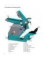
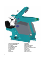
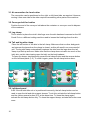
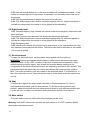
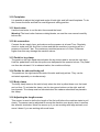
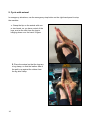
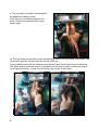
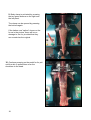
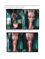
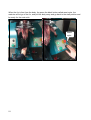
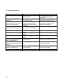
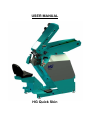
USER MANUAL HG Quick Skin Table of contents Table of contents .................................................................................................................2 Introduction ..........................................................................................................................3 1. Safety...............................................................................................................................4 1.1 Use .........................................................................................................................5 1.2 Training ...............................................................................................................5 1.3 Positioning, spatial requirements, etc. .................................................................5 1.4 Preparation..........................................................................................................6 1.5 Noise level...........................................................................................................6 1.6 Maintenance........................................................................................................6 1.7 Dismantling/Disposal ...........................................................................................6 2. Transport and manoeuvring.............................................................................................7 3. The machine’s functional units.........................................................................................8 3.1 Air connection for head cutter...................................................................................10 3.2 Conveyor belt for bodies ..........................................................................................10 3.3 Leg clamp.................................................................................................................10 3.4 Tail and leg skin clamp .............................................................................................10 3.5 Left-hand panel ........................................................................................................10 3.6 Right-hand panel ......................................................................................................11 3.7 Electrical panel .........................................................................................................11 3.8 Seat..........................................................................................................................11 3.9 Main switch ..............................................................................................................11 3.10 Footplates ..............................................................................................................12 3.11 Head cutter.............................................................................................................12 3.12 Air connection.........................................................................................................12 3.13 Pedal for leg clamp.................................................................................................12 3.14 Pedals for skin and body pull..................................................................................12 3.15 Body clamp.............................................................................................................12 3.16 Adjusting the length sensor ....................................................................................12 3.17 Mist lubricator .........................................................................................................13 2 3.18 Skin support clamp.................................................................................................13 4. Set-up and connection ...................................................................................................13 4.1 Set-up.......................................................................................................................13 4.2 Connection ...............................................................................................................13 5. Cycle with animal. ..........................................................................................................14 5.1 Emergency stop cycle ..............................................................................................22 6. Maintenance and cleaning .............................................................................................22 7. Sitting position ...............................................................................................................23 8. Troubleshooting .............................................................................................................24 9. Technical data. ..............................................................................................................25 Dimensions and weight: .................................................................................................25 Electricity:.......................................................................................................................25 Compressed air..............................................................................................................25 Warranty.........................................................................................................................25 10. EU Declaration of conformity .......................................................................................26 Introduction HG Quick Skin is intended for skinning mink in pelting centres. HG Quick Skin has been designed to function as a simple, user-friendly and ergonomic product that meets all requirements for occupational health and safety. 3 1. Safety Read the manual Machine operator must read this manual carefully and receive training in the machine’s functions before starting to work with it. If operator are ignorant of certain details, they may be at risk of physical injury when operating the machine. If any of the warning labels are about to fall off – or so worn or damaged that the symbol is not clearly visible, the label in question must be replaced. WARNING! High voltage. Before opening the electrical panel, make sure to disconnect the power supply and lock it in the <OFF> position to prevent unintentional reconnection. After disconnecting the power supply, wait for ten minutes before working on the components in the electrical panel because the frequency converters store current. Only authorised personnel are permitted to open the electrical panel. WARNING! Ear protectors required Both operator and any people in the immediate vicinity of the machine must wear ear protectors as the noise level exceeds 70 dB(A), which is the normally permitted level. 4 WARNING! Crushing risk Do not touch the moving parts of the machine. This applies both to fingers and items of clothing, because there is a risk of serious injury if either comes into contact with these parts. 1.1 Use The machine may only be used in industrial contexts for processing mink, i.e. with the objective of removing the skin from the mink body. Operators must be over 18 years of age, in good health with normal mobility and physical attributes. It is essential that operators establish a good, ergonomically correct sitting position when using the machine. 1.2 Training Before starting to work with the machine, operators must read the instructions in this manual carefully and familiarise themselves with the correct operating procedure – in consultation with an experienced instructor, if appropriate. Such instruction should emphasise: 1. The need to be careful, thorough and focused when working with the machine. 2. Ensuring that the operator maintains a good overview of the area around the machine. The operator is responsible for any and all accidents and/or dangerous situations that may arise in respect to other people. The most common causes of accidents are: 1. Lack of concentration. 2. Operators who are insufficiently familiar with the machine. 1.3 Positioning, spatial requirements, etc. The machine must be positioned indoors on a flat, solid surface. When working with the machine, the area must be illuminated by flicker- and glarefree lights of at least 300 lux. 5 The area around the machine must be kept neat and tidy to prevent accidents that involve tripping and falling. Cables and hoses connected to the machine must be laid out so that they do not constitute a risk – away from walking areas, above head height or in appropriate cable trays on the floor, for example. 1.4 Preparation When operating the machine, do not to wear loose-fitting clothing and do not let your hair hang loose if it is long. The reason for this is to eliminate the risk of your hair or clothes becoming caught in the machine or entangled in its rotating parts. In addition, make sure to wear footwear with a firmly gripping sole to prevent the risk of slipping. Always keep grease, oil and other such materials for maintaining the machine in containers approved for the purpose. Store these materials out of reach of children and non-authorised persons. 1.5 Noise level As the noise level is above the normally permitted limit, operators and people in the vicinity of the machine must wear ear protectors while the machine’s head cutter is operating. 1.6 Maintenance Inspect the machine every day to check for visible faults and defects. Also make sure to check whether any guides and other moving parts have become jammed by fat, blood, sawdust or other foreign objects. Visually inspect the machine to check the following: That there are no leaks in the compressed air systems (hoses, etc.) That all bolts, nuts, etc. are securely tightened That all guides and carriages are intact and appropriately lubricated That all chains are intact, correctly tensioned and appropriately lubricated. See Section 6 of this manual for details of how to maintain the machine otherwise. 1.7 Dismantling/Disposal When the time comes to dispose of the machine, contact your local dealer to ensure that the machine is dismantled and disposed of in the most environmentally appropriate manner. 6 2. Transport and manoeuvring Always use a pallet truck or forklift to transport/lift the machine, and always lift at the ends. If the machine needs to be secured for transport, run straps across the base of the machine at the points indicated. Do not run straps across the conveyor belt, the body puller or the seat, as this may damage these parts. Do not attempt to use a crane to lift the machine. Warning! Do not attempt to move the machine using equipment that is not suited to the purpose. 7 3. The machine’s functional units 2 3 4 15 5 7 8 1 9 10 13 12 10 1. Air connection for head cutter 2. Conveyor belt for bodies 3. Leg clamps 4. Tail and leg skin clamp 6. Right-hand panel 5. Left-hand panel 7. Electrical panel 8. Seat 9. Main switch 8 10. Footplates 11. Head cutter 12. Air connection/fine filter 13. Pedal for leg clamp 14. Pedals for skin and body pullers 15. Body clamp 16. Length adjustment 17. Mist lubricator 18. Skin support clamp 16 11 18 6 17 14 1. Air connection for head cutter 2. Conveyor belt for bodies 3. Leg clamp 4. Tail and leg skin clamp 6. Right-hand panel 5. Left-hand panel 7. Electrical panel 8. Seat 9. Main switch 9 10. Footplates 11. Head cutter 12. Air connection/fine filter 13. Pedal for leg clamp 14. Pedals for skin and body pullers 15. Body clamp 16. Length sensor 17. Mist lubricator 18. Skin support clamp 3.1 Air connection for head cutter The connection can be positioned on the right- or left-hand side, as required. However, moving it from one side to the other requires remodelling other parts of the machine. 3.2 Conveyor belt for bodies Position the end of the conveyor belt above the container or conveyor used to dispose of the cadavers. 3.3 Leg clamp This is where to place the mink’s hind legs once the skin has been loosened on the HG Combi Cut or a different cutting machine used to loosen the hind legs from the skin. 3.4 Tail and leg skin clamp Place the tail section of the skin in the tail clamp. Make sure that no other body parts are between the jaws when the clamp is closed, as this will result in an unsuccessful pull. The leg skin clamp automatically captures the skin from the legs when the tail clamp is pulled up and over. Make sure that the clamp does not catch too much of the belly skin, as this risks tearing open the belly on the body/cadaver. To open the clamp, simultaneously press the tail clamp button and the reverse button on the left-hand panel (3.5). To close it again, press the tail clamp button alone. 5.1 5.3 5.2 5.4 6.1 6.2 6.3 6.4 3.5 Left-hand panel 3.5.1 If the tail skin falls out or is positioned incorrectly, the tail clamp button can be used to open the tail and skin support clamps. To do this, activate the tail clamp button and the yellow reverse button (5.2) at the same time. To close the clamp again, activate the tail clamp button only. To close the support clamp, activate the button once more. 10 3.5.2 Use the reverse button to run the skin and body pull functions backwards – if the animal is not centred in the body clamp, for example, or if the body or skin falls out of the clamps. 3.5.3 Use the potentiometer to adjust the speed of the skin pull. 3.5.4 The body clamp button must be activated together with 6.2 (right-hand panel) to activate the clamp when the animal is to be gripped at the shoulders. 3.6 Right-hand panel 3.6.1 ‘Reset emergency stop’ restarts the machine after the emergency stop button has been activated. The button functions as a backup if the clamp rails have been activated. 3.6.2 The body clamp button must be activated together with 5.4 (left-hand panel) to activate the clamp when the animal is to be gripped at the shoulders. 3.6.3 Emergency stop 3.6.4 ‘Reset cycle’ restarts the machine cycle and returns to the start position once the skin has been removed from the animal. The button can also be activated in the middle of the cycle to restart. 3.7 Electrical panel To open the electrical panel, use the plastic key supplied with the machine. WARNING: Before opening the electrical panel, make sure to disconnect the power supply and lock it in the <OFF> position to prevent unintentional reconnection. After disconnecting the power supply, wait at least ten minutes before working on the components in the electrical panel because the frequency converters store current. This panel must never be opened by non-authorised staff as the consequences could be fatal. The motor protection units are located in the electrical panel. If a red button is ‘in’, then the motor has cut out. Press the black button in if the motor protection switch has cut out. 3.8 Seat To adjust the height of the seat, loosen the bolts on the seat bracket. To move it backwards and forwards, pull the seat rail bars. To find the most ergonomic work position, adjust the seat so that your elbows are as close to your body as possible and you do not have to raise your shoulders when placing an animal in the machine. 3.9 Main switch The main switch must be <ON> before the machine can be used. Warning! You MUST disconnect and lock the main switch in its <OFF> position before starting any maintenance work. 11 3.10 Footplates It is possible to adjust the height and angle of both right- and left-hand footplates. To do this, loosen the bolts and find the most ergonomic sitting position. 3.11 Head cutter Use the head cutter to cut the skin free around the head. Warning! The head cutter features rotating blades, so read the user manual carefully before use. 3.12 Air connection Connect the air supply here, and make sure the pressure is at least 7 bar. Regularly check to make sure the fine filter is clean and that the machine is receiving air at a pressure of at least 7 bar. The maximum permitted pressure is 9.5 bar. Pressures higher than this may damage the machine valves. 3.13 Pedal for leg clamp The pedal on the right-hand side activates the leg clamp used to secure the mink legs. Hold the pedal down until the skin-puller arm has passed the operator’s knee. The pedal can then be released. If it is released earlier, the machine will stop. 3.14 Pedals for skin and body pull The pedals on the right-hand side control the skin and body pullers. They can be activated separately or simultaneously. 3.15 Body clamp The body clamp secures the mink’s body when the skin is pulled down over the head and cut free. To activate the clamp, use the two green buttons on the right- and lefthand panels. The clamp must be activated when the cadaver shoulders are placed in the clamp. 3.16 Adjusting the length sensor This sensor is used to define the length of the first pull before the machine starts to pull slowly. The sensor can be adjusted to ensure the machine runs slowly when it reaches the animal’s shoulders. Move the sensor up if you are working with large animals, and move it down if you are working with small ones. 12 3.17 Mist lubricator The mist lubricator ensures that the head cutter is lubricated properly, runs optimally and lasts longer. Remember to fill the mist lubricator container regularly with mist lubrication oil. HG item no. 476560 3.18 Skin support clamp The skin support clamp helps to pull the skin when it has to be pulled down over the mink’s shoulders. The clamp closes when the length sensor (3.16) is activated. The clamp can be opened by pressing the tail clamp button and the reverse button at the same time. The clamp closes again when the tail clamp button is pressed for the second time. 4. Set-up and connection HG recommends that one of the company’s trained fitters sets up the machine so as to ensure optimal flow and process conditions. 4.1 Set-up The machine must be positioned indoors on a flat, solid floor. The ceiling height must be at least 225 cm. In accordance with standard EN 12465-1:2002 the operating area must be illuminated with at least 300 lux. 4.2 Connection Electricity: Connect the machine to a 3 x 400 volt power supply with neutral (N) and earth (PE) conductors, fused with min. 16A. The connection is to feature a CEE plug or a supply separator that can be disconnected safety during maintenance procedures and/or repairs to the machine. Air: The machine requires compressor pressure of at least 7 bar. Use a type Cejn 320 quickrelease coupling to connect the air supply. To avoid stoppages, make sure that the air supplied to the machine is free from water, dirt and rust from old pipes. The maximum permitted compressor pressure is 9.5 bar. Pressures higher than this may damage the machine valves. Warning! Do not leave air hoses and electricity cables lying unsecured on the floor, as this constitutes a risk of physical injury. 13 5. Cycle with animal. In emergency situations, use the emergency stop button on the right-hand panel to stop the machine. 1. Grasp the hip on the animal with one or two hands, so you have control of the legs, and so the skin from the legs is hanging down over the hand / fingers. 2. Place the animal so that the legs are in leg clamp, so that the leather side of the pelt is up against the rubber from the leg skin clamp. 14 3. The leg clamp is closed by pressing the left pedal and holding it down. If the legs are not placed properly in the clamp, release the pedal and the clamp opens again. 4. The leg clamp is know shut, let the animal hang loose in the leg clamp, (Left pedal is still held down) grab the tail skin from the animal, while the second hand pushes the tail clamp over the animal, while the tail skin is put in the clamp, the clamp closes automatic when it is pushed over the animal (watch out that our fingers do not get the clamp). The tail from the body may not get in the clamp. 15 5. The leg skin clamp closes with tail clamp and will grab the leg skin where the skin is not caught, can the tail clamp be pushed aside, and the clamps open again. The leg skin clamp only need to get hold of a little part the leg skin on each side for the pull to succeed. 6. Adjusting when the slow pull is activated is done by moving the sensor on the side of the body cover. The sensor is activated when Leg clamp runs up past the sensor. The sensor makes the machine pull slowly and support clamp for the skin closes, and the leg skin clamp opens Adjust the sensor so that it will slow down when just before the skin is pulled off to the shoulders of the animal. 16 7. Pull by stepping on both pedals simultaneously, skins and body will now be pulled apart. Pull until the shoulders are pulled free and the dividing line is in the center of the shoulder clamp. Dividing line If the dividing line is not in the center, you can adjust by pressing the pedal for skin pull or body pull, or if they are extended too far, you can reverse by holding down the yellow button (Reverse) and then pressing either the pedal for skin pull or body pull. 8. If the dividing line is not in the center of the clamp after the pull, then you can either increase or decrease the fur pull speed. • If the dividing line is under the clamp you must decrease the fur speed. • If the dividing line is above the clamp you must increase the fur speed. Dividing line 17 9. Body clamp is activated by pressing the two green buttons on the right and the left panel. The clamp can be opened by pressing the buttons again. If the bottom row "spikes" closes on the fur as in the picture, there will be no damage to the fur, provided that they are rounded as the original. 10. Continue pressing on the pedal for fur pull until the skin is pulled down over the shoulders to the head. 18 11. Use the decapitator to cut the fur free from the neck down on the mink, make the first cut about 10mm above the dividing line by the ears. Press the fur pull pedal and pull down to the eyes, and apply a cut by the eyes. 19 Press the fur pull padal again, and pull down to the nose, and put a cut in the jaw and nose to get the skin off from the body, hold the skin with one hand so the fur does not fall onto the bottom of the machine. Grab the fur. Cut or pull of. 20 When the fur is free from the body, the press the black button called reset cycle, the machine will let go of the fur, and pull the body away and go back to the start position and be ready for the next mink. Reset cycle 21 5.1 Emergency stop cycle If an emergency stop situation arises – if an object becomes caught in the machine’s safety edges, for example – you can usually deal with the problem by reversing the machine operation. Keep the green <Reset emergency stop> button depressed and activate the pull pedals. The machine can only reverse a short distance. After the object has been removed, you can run the machine back once all the emergency stop and clamp rails have been deactivated and the green <Reset emergency stop> button is illuminated. 6. Maintenance and cleaning Warning! You MUST disconnect and lock the main switch in its <OFF> position before starting any kind of maintenance work. Normal cleaning After finishing work, check the machine for foreign objects that may have become caught in it. Use a compressed air pistol to remove wool and dirt from the machine parts. Use compressed air to remove any dirt from the motors’ radiator fins. Use a vacuum cleaner to remove dust and wool from the floor around the machine. Regularly check the surfaces of the fan/motors for dust and other impurities. If the layer of dust is more than 0.5 mm thick, it must be removed. NB Always wear a dust mask, protective goggles and ear protectors when using compressed air to clean the machine. Lubricating bearings and guides Grease the machine bearings. There are four flange bearings to lubricate. There are also two sets of guide rails and carriages on the machine that need to be lubricated. Tightening chains The machine is fitted with two chains. Make sure that both chains are sufficiently taut. Consumables We recommend grease type Q8 Rembrandt EP 2, – HG item no. 476570 – for lubricating bearings with nipples. For lubricating the guides, we recommend using guide oil, HG item no. 476590 For lubricating the head cutter, make sure to fill the mist lubricator container with mist lubricant: HG item no. 476560 Protection devices It is only permitted to remove any of the protection devices on the machine in connection with repairs or service procedures. This must only be done by appropriately trained personnel. 22 Storage When you have finished using the machine for the season, it is important to clean it thoroughly and make sure that it is properly lubricated. Grease the lubrication nipples. Lubricate the guides with guide oil. 7. Sitting position As the operator, it is important that you sit comfortably at the machine – and not too low in relation to where the animal is to be positioned in the leg clamp. Avoid raiding your shoulders when placing the animal in the machine. Adjust the pedals so that your feet rest comfortably on the plates. Angling the footplates slightly forward can prevent your legs from ‘sleeping’ and eliminate the problem of tensing up. Make sure that animals, sawdust and other work tools are within easy reach. As the operator, you should not have to lift animals from a surface that is farther away than you can reach comfortably by straightening your elbow – i.e. without moving your body. Nor should you have to twist your back while working. 23 8. Troubleshooting Problem Machine will not start. Possible cause Emergency stop activated, no power supply. Conveyor belt running the wrong way. The clamp rails are activated when the machine is running back to the start position. The phases in the plug are in the incorrect order. Defective sensor. The sensor is positioned incorrectly on either skin or body pull. Defective reed sensor on the ‘tail clamp turn in’ cylinder. The skin clamps do not close when the tail clamp is turned in. Skin puller does not work. Body puller does not work. Leg clamp will not close. Reset cycle: body clamp opens, but machine does not return to start position. The body pull drops off slightly when the machine returns to the start. HPFI relay trips when the machine is switched on. 24 Solution Check all emergency stops, incl. clamp rails and power connection. Reverse the order of the phases in the machine plug. Check the skin and shoulder pull sensors. If they are not defective, adjust them. Replace the reed sensor. Defective or hanging switch in pedal. Defective or hanging switch in pedal. Defective or hanging switch in pedal. Defective reed sensor on body clamp cylinder. Replace switch unit. Brake relay tripped. Press the appropriate relay in the electrical panel. Short circuit. Insufficient power to the machine. Contact your local electrician to check the supply. Replace switch unit. Replace switch unit. Replace reed sensor if defective, or secure it if loose. 9. Technical data. Dimensions and weight: Width: 80 cm Length: 216 cm Height: 220 cm Weight: 500 kg Electricity: Voltage: 3 x 400 V + N + PE Fuses: 16 A Connection: 16A CEE PLC control: 230 V AC + 24 V DC Compressed air Air pressure: Min. 7 bar, Max. 9.5 bar Connection: Cejn 320 quick-release coupling Warranty HG Quick Skin comes with a 12-month warranty. Defective parts will be replaced if the fault is attributable to a manufacturing error. Faults and defects attributable to shipping are not covered by this warranty. In the event of incorrect operation of the HG Quick Skin machine, no warranty coverage shall apply to damage to either the machine or skins. 25 10. EU Declaration of conformity Hedensted Gruppen A/S Vejlevej 15 DK-8722 Hedensted Tel. +45 75 89 12 44 Fax: +45 75 89 11 80 www.hedensted-gruppen.dk hereby declares that: HG Quick Skin HG item no. 206330 conforms with: - The Machinery Directive 2006/42/EC - The Low Voltage Directive 73/23/EEC - The ROHS Directive 2011/65/EU under application of harmonising standards: - DS/EN 12100-1:2005 - DS/EN 13857:2008 - DS/EN 60439-3 Hedensted, 15 October 2014 26