1
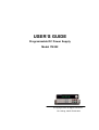
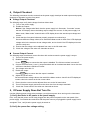
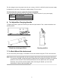
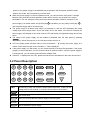
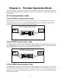
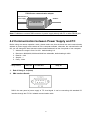
USER’S GUIDE Programmable DC Power Supply Model IT6322 © Copyright 2005 All Rights Reserved Ver1.0/Aug, 2005/ IT6300-508 CHAPTER 1 QUICK START .............................................................................................. 6 1.1 Front Panel & Rear Panel.......................................................................................................................................6 1.2 Preliminary Checkout ..............................................................................................................................................7 1.Check the list of supplied items..........................................................................................................................7 2.Connect the power cord and turn on the power supply..................................................................................7 3. System Checkout ...................................................................................................................................................7 4.Output Checkout...................................................................................................................................................9 5.If Power Supply Does Not Turn On ...................................................................................................................9 6.To Adjust the Carrying Handle .........................................................................................................................10 7. To Rack Mount the Instrument...........................................................................................................................10 CHAPTER 2 SPECIFICATIONS.................................................................................... 11 2.1 Specifications.......................................................................................................................................................... 11 2.2 Supplemental Characteristics ..............................................................................................................................12 CHAPTER 3 FRONT-PANEL OPERATION .................................................................. 12 3.1 Front-panel Operation Overview..........................................................................................................................12 3.2 Panel Description...................................................................................................................................................13 3.3 VFD Description and Wiring Diagram .................................................................................................................14 3.4 Menu Descriptions .................................................................................................................................................14 3.5 Panel Operation .....................................................................................................................................................15 3.6 Menu Function........................................................................................................................................................18 Power Config ....................................................................................................................................................18 System Set........................................................................................................................................................19 Power Information ............................................................................................................................................20 CHAPTER 4 REMOTE OPERATION MODE................................................................. 22 4.1 Communication cable............................................................................................................................................22 4.2 Communication between Power Supply and PC ..............................................................................................23 2 IT6322 Programmable DC Power Supplies General information The following safety precautions should be observed before using this product and any associated instrumentations. Although some instruments and accessories would be used with non-hazardous voltages, there are situations where hazardous conditions may be present. This product is intended for use by qualified personnel who recognize shock hazards and are familiar with the safety precautions required to avoid possible injury. Read and follow all installation, operation, and maintenance information carefully before using the product. Refer to this manual for complete product specifications. If the product is used in a manner not specified, the protection provided by the product may be impaired. Before performing any maintenance, disconnect the line cord and all test cables. Protection from electric shock Operators of this instrument must be protected from electric shock at all times. The responsible body must ensure that operators are prevented access and/or insulated from every connection point. In some cases, connections must be exposed to potential human contact. Product operators in these circumstances must be trained to protect themselves from the risk of electric shock. If the circuit is capable of operating at or above 1000 volts, no conductive part of the circuit may be exposed. Definition of users Responsible body is the individual or group responsible for the use and maintenance of equipment is operated within its specifications and operating limits, and for ensuring that operators are adequately trained. Operators use the product for its intended function. They must be trained in electrical safety procedures and proper use of the instrument. They must be protected from electric shock and contact with hazardous live circuits. Service is only to be performed by qualified service personnel. We do not accept responsibility for any direct or indirect financial damage or loss of profit that might occur when using the electronic load. About your safety The following general safety precautions must be observed during all phases of operation of this instrument. Failure to comply with these precautions or with specific warnings elsewhere in this manual violates safety standards of design, manufacture, and intended use of the instrument. ITECH assumes no liability for the customer’s failure to comply with these requirements. 3 Safety symbols and terms Connect it to safety earth ground using the wire recommended in the user manual. The symbol on an instrument indicates that the user should refer to the operating instructions located in the manual. High voltage danger Certification and Warranty Certification We certify that this product met its published specifications at time of shipment from the factory. Warranty This instrument product is warranted against defects in material and workmanship for a period of one year from date of delivery. During the warranty period we will, at its option, either repair or replace products which prove to be defective. For warranty service, with the exception of warranty options, this product must be returned to a service facility designated by us. Customer shall prepay shipping charges by (and shall pay all duty and taxes) for products returned to the supplier for warranty service. Except for products returned to customer from another country, supplier shall pay for return of products to customer. Limitation of Warranty The foregoing warranty shall not apply to defects resulting from improper or inadequate maintenance by the Customer, Customer-supplied software or interfacing, unauthorized modification or misuse, operation outside of the environmental specifications for the product, or improper site preparation and maintenance. Introduction IT6300 3 channels power supply has high accuracy and high stability, also has the function of the limit voltage, over current and over temperature protection. You can set the voltage and value of from 0V to the max value in every channel. This series power supply can be connected in series and in parallel connection, it could improve the output ability of the voltage and the current value to twice. It is the best choice for the quality test in the scientific research laboratory and the product line. z z z z z z All of 3 channels can output and change voltage Can be connected in series or parallel connection Voltage and current of 3 channels can be displayed at the same time Small size with 1/2 2U VFD display High resolution and high accuracy 4 z z z z z z z z Output on/off Limit voltage, over current and power protection Low ripple and low noise Communication port: USB/GPIB/RS232 Free software for control and calibration Fifty operation states storage Set voltage and current value with rotary knob Set output time1~999999S 5 Chapter 1 Quick Start One of the first things you will do with your power supply is to become acquainted with the front panel. The exercises in this chapter prepare the power supply for use and help you get familiar with some of its front-panel operations 1.1 Front Panel & Rear Panel Front panel 2 1 3 4 1 VFD display 2 Rotary knob 3 Power switch 4 Number keys and “Esc” key 5 Function key 6 UP, Down key and “Enter” ket 7 Output terminals 5 6 Rear Panel 6 7 1 2 3 4 5 ① Cooling window ② DB9 interface connector ③ 110V/220V Power switch ④ Fuse ⑤ Power socket 1.2 Preliminary Checkout The following steps help you verify that the power supply is ready for use. 1.Check the list of supplied items Verify that you have received the following items with your power supply. If anything is missing, contact your nearest Sales Office. One power cord for your location This User’s Manual. Calibration Report Communication cable (optional) 2.Connect the power cord and turn on the power supply When you turn on the power supply, the front-panel display will light up briefly while the power supply performs its power-on self-test. All the VFD annunciators will light up at once. To review the display with all annunciators, you can check if there is any stroke loss on any annunciator. If there isn’t any response when you power on the power supply, please see Section 5 on page 8 for some service information. 3. System Checkout When the power supply was powered on, the system will checkout it self, and VFD will display as follows: 7 System Test, Please wait! If EEPROM was damaged, the VFD will display as follows: EEPROM Error If the latest operation data in EEPROM was lost, the VFD will display as follows: Data Check Error If the latest data about off-time in EEPROM was lost, the VFD will display as follows: Load OffTime Fail If the calibration data in EEPROM was lost, the VFD will display as follows: CH X Lost Calibration... Note: “X” denotes the channel which has lost calibration data. If the calibration data in EEPROM was error or tthe information calibrated by factory was lost, the VFD will display as follows: Lost Factory Calibration VFD displays: the first row is output voltage, the second row is the state when the power supply is on or current. 0.000V <OFF> 0.000V <OFF> 0.000V <OFF> Or: 10.000V 11.000V 3.000V 2.000A 3.000A 3.000A Note: there will be a “?” on the VFD if there is error when the system checkout. 8 4.Output Checkout The following procedures check to ensure that the power supply develops its rated outputs and properly responds to operation from the front panel. Voltage Output Checkout The following steps verify basic voltage functions without load. 1) Turn on the power supply. 2) Enable the outputs 3) 4) 5) Notice: if the voltage value flash, then the power supply is in Set mode, ‘‘Set mode’’ means that the VFD display shows the setting output voltage and current. Or the power supply is in Meter mode, ‘Meter mode” means that the VFD display shows the actual output voltage and current. Check that the front-panel voltmeter properly responds to number keys Set some different voltage values, then wait till the Meter mode to check if the VFD displayed voltage value is the same as the set voltage value, and to check if the VFD displayed current value is nearly zero. Ensure that the voltage can be adjusted from zero to the full rated value Check the voltage of the other two channels as above. Current Output Current The following steps check basic current functions with a short across the power supply’s output. 1) Turn on the power supply 2) Disable the output 3) 4) 5) 6) 7) 8) 9) Press On/Off key to ensure that the output is disabled. The ON annunciator is turned off. Connect a short across (+) and (-) output terminals with an insulated test lead. Use a wire size sufficient to handle the maximum current. Set voltage value with 1V Enable the output Press On/Off key to ensure that the output is enabled. Adjust the current value Set some different voltage values, then wait till the Meter mode to check if the VFD displayed current value is the same as the set current value. Ensure that the current can be adjusted from zero to the full rated value. Turn off the power supply and remove the short wire from the output terminals. Check the current value of the other two channels as above. 5.If Power Supply Does Not Turn On Use the following steps to help solve problems you might encounter when turning on the instrument. 1). Verify that there is AC power to the power supply. First, verify that the power cord is firmly plugged into the power receptacle on the rear panel of the power supply. You should also make sure that the power source you plugged the power supply into is energized. Then, verify that the power supply is turned on. 2). Verify the power-line voltage setting. 9 The line voltage is set to the proper value for your country (110VAC or 220VAC) when the power supply is shipped from the factory. Change the voltage setting if it’s not correct. 3). Verify that the correct power-line fuse is installed. If the fuse was damaged, please see the table below to replace the fuse for your power supply. Model Fuse Description IT6322 Fuse 3.15A T250V(220V AC) Fuse 6.30A T250V(110V AC) 6.To Adjust the Carrying Handle To adjust the position, grasp the handle by the sides and pull outward. Then, rotate the handle to the desired position. Bench-top viewing positions Carrying position 7. To Rack Mount the Instrument You can mount the power supply in a standard 19-inch rack cabinet using the IT-E151 rack mount kit. Note: Remove the carrying handle and the two plastic ears before rack-mounting the instrument. To remove the handle, grasp the handle by sides and pull outwards and rotate it to a special position to let the arrow on the handle and the arrow on the plastic ears be in opposite directions, then pull the handle outward. After removing the handle, you can use a screwdriver to remove the two plastic ears. 10 Chapter 2 Specifications 2.1 Specifications Paramete IT6322 The model of remote sense Voltage ±(%of output+offset) Current 0~30V×2,0~5V×1 0~3A×2,0~3A×1 0~31V×2,0~6V×1 ≤0.01%+3mV ≤0.01%+3mA Line Regulation Voltage ≤0.01%+3mV ±(%of output+offset) Current ≤0.1%+3mA Programming Voltage Resolution Current Readback Voltage 1mV 1mA 1mV Resolution Current 1mA Programming accuracy Voltage ≤0.03%+10mV ±(%of output+offset) Current ≤0.1%+5mA Readback accuracy Voltage ≤0.03%+10mV ±(%of output+offset) Current ≤0.1%+5mA Ripple & noise Voltage Ripple≤1mVrms/3mVp-p Noise≤3mVrms Temperature coefficient Voltage ≤0.03%+10mV ±(%of output+offset) Current ≤0.1%+5mA Readback accuracy Voltage ≤0.03%+10mV ±(%of output+offset) Current ≤0.1%+5mA Output ratings Voltage ( 0 °C - 40 °C) Current LVP (12 months) (25 °C ± 5 °C) (0 °C ~ 40 °C) Synchro Synchro operation in error in Series connection series ≤0.05%+10mA connection Synchro operation in parallel Voltage ≤0.02%+5mV Programming accuracy Current ≤0.1%+20mA Storage memory Store/recall 50 user-configurable stored states Time set 1S~999999S Resolution 1S Function Auto Step Running connection Timer 11 2.2 Supplemental Characteristics State Storage Memory 9 user-configurable stored states Recommended Calibration Interval 1 year AC Input Ratings (selectable via switch on the rear panel) Option Opt.01: 220AV±10%,47~63HZ Option Opt.02: 110AV±10%,47~63HZ Maximum input power Model IT6322 Power 750VA Cooling Fan cooled Operating Temperature 0 to 40 °C for full rated output Storage Temperature -20 to 70 °C for storage environment. Environmental Conditions Designed for indoor use in an installation category II, pollution degree 2 environment. Designed to operate at maximum relative humidity of 95% and at altitudes of up to 2000 meters. Chapter 3 Front-panel Operation So far you have learned how to install your power supply and do quick start. During the quick start, you were briefly introduced to operating from the front panel as you learned how to check basic voltage and current functions. This chapter describes in detail the use of the front-panel keys and shows how they are used to accomplish power supply operation. 3.1 Front-panel Operation Overview The following section describes an overview of the front-panel keys before operating your power supply. z The power supply is shipped from the factory configured in the front-panel operation mode. At 12 power-on, the power supply is automatically set to operate in the front-panel operation mode. When in this mode, the front panel keys can be used. z When the power supply is in remote operation mode, you cannot use the front-panel. A change between front-panel and remote operation modes will not result in any change in the output parameters. You can change the front-panel and remote operation modes by computer. If the power supply is in remote mode, and [LOCAL]key ● is enabled, you can press [LOCAL]key ● and the power supply will be in panel mode. z The power supply is in Meter mode when it is powered on, and the VFD will display the actual voltage and current output value. And in the mode, And in this mode, if the knob is screwed, the power supply will changed to Set mode, and the VFD will display the adjusted voltage and current value. z The output of the power supply can be enabled or disabled from the front panel by pressing On/Off key. When the output is on, the ON annunciator will turn on. z VFD can display some operation state or error information. “ ”means the power supply is in remote. And if there is some error information,”?” will be displayed. z If the power supply is in Set mode, you can screw the knob to change the parameter. If the power supply is in menu operation, you can screw the knob to select the menu. And if the power supply is in testing mode, you can screw the knob and set voltage value. z If there is “?” displayed on the VFD, please consult the error information in the menu and check it. 3.2 Panel Description 1 2 3 Esc V-set I-set 4 5 6 0 Save Recall 7 8 9 ● Menu On/Off 0~9 Enter Number key(1~3key can control the output state of 3channels,。4~6key can set voltage value for the channel, 7~9 can set current value for the channel.) V-set I-set Set voltage value Set current value Save Save the currently data of the power supply to internal register Recall Recall the data from the internal register Menu Set the parameter f power supply 13 On/Off Set the output state of power supply Up key, select the menu or channel Down key, select the menu or channel 3.3 VFD Description and Wiring Diagram There are some sighs on the VFD when the power supply is on, which denotes different meaning. The output is off. OFF The key panel is locked. The power supply is in remote mode. There is some error or fault with the power supply. ? Channel sign 3.4 Menu Descriptions Press Menu to indicate operation mode. View the menu in VFD, and use or knob to scroll through the complete menu list as following. If press Enter , you could get the selected menu function, press Esc back to the previous menu selection page. If there is”↑↓” on the left of VFD, it means that this key to select other menu function. If menu function is in the mid of all menu and you can press there is only”↑”, it means that you can only press to select the menu. And if there is only”↓” on the left of VFD, it means that you can only press to select the menu. If there is “ ” on the VFD, it means this menu function is selected. Menu Power Config... Reset Config System reset Out State Set Set the output state when power-on Out Parameter Set Set whether to save the output state of last time Key Sound Set Knob Function Set Screen Brightness Baud Rate Set Set communication baud rate Communication Parity System Wait Time Local Address Set communication address Key Lock Set Set password 14 Exit System Set… Out Series Set Set series connection Out Parallel Set Set parallel connection Max Voltage Set… Set max voltage for each channel Set First Channel Set Second Channel Set Third Channel Out Time Set… Set output time for each channel Set First Channel Set Second Channel Set Third Channel Exit Power Information… Power Model Power SN Soft Version Cal Information Error Information Exit Exit Menu 3.5 Panel Operation Channel Operation When the power supply is in “METER” mode, you can press 、 key to select the channel. OUT ON/OFF Press On/Off to change output state of power supply. If the output state is ON, press it, the output state will be OFF. While the output state is OFF, press On/Off and the state will be ON. When the power supply is in panel operation, you can press On/Off to control the output state of all 1 1 2 , 3 )to control one channel’ output state. Key controls the output state of the first channel, key 2 controls the output state of the second channels. Or you can press one number key( channel, key 3 , controls the output state of the third channel. When the power supply is in remote mode, you can send SCPI order(OUTPut: ON | OFF) to set the output state. Output state operation doesn’t affect setting parameter. Note: pressing On/Off is to control the output state of 3 channels at the same time. If you want to control one channel’s output state, please use the single key for each 15 channel. Timer Operation If you have set output time and the power supply is in “METER” mode, you can press 0 to see the remainder time. When the time is counted down, the power supply will turn off the channel automatically. Setting Voltage When the knob function is enabled: V-set Solution 1: Press Solution 2: Press V-set press Esc +numeric key, press Enter to confirm. , then press to select cursor position and screw the knob to set voltage, or Enter to exit. Solution 3: Press one number key which can control channel’s voltage setting (pressing number key 4 can control the first channel, pressing number key 6 channel and pressing number key 5 can control the second can control the third channel). For example, if you want to set voltage for the first channel, you can press number key key+ Enter to set voltage, or press knob to set voltage value, press Esc or Enter 4 , then press number to change the cursor, and then screw the to escape. When the knob function is disabled: Solution 1: Press V-set +numeric key to set voltage value, press to change the value slightly, press Enter to confirm. Solution 2: Press one number key which can control channel’s voltage setting (pressing number key 4 can control the first channel, pressing number key channel and pressing number key key or press 6 5 can control the second can control the third channel), then press number to set voltage value, press Enter to confirm. 16 Setting Current When the knob function is enabled: I-set Solution 1: Press Solution 2: Press I-set press Esc +numeric key, press Enter to confirm. , the press to select cursor position and screw the knob to set voltage, or Enter to exit. Solution 3: Press one number key which can control channel’s current setting (pressing number key 7 can control the first channel, pressing number key channel and pressing number key 9 8 can control the second can control the third channel). For example, if you want to set current for the first channel, you can press number key key+ Enter to set voltage, or press knob to set voltage value, press Esc or Enter 7 , then press number to change the cursor, and then screw the to escape. When the knob function is disabled: Solution 1: Press I-set +numeric key to set voltage value, press to change the value slightly, press Enter to confirm. Solution 2: Press one number key which can control channel’s current setting (pressing number key 4 can control the first channel, pressing number key channel and pressing number key key or press 6 5 can control the second can control the third channel), then press number to set current value, press Enter to confirm. Saving and Recalling Operation You can store up to 50 different output states in storage register locations (1 to 9). Each output state includes Constant voltage value, Constant current value and Maximum output voltage value, voltage step value. Press Save +number key, and save voltage and current value into register. Pressing Recall +number key can recall the value. Or you can use SCPI order:*SAV、*RCL to save and recall. Over Temperature Protection 17 If the power supply inside temperature is over 80℃, it will protect itself. And the output state is OFF, the buzzer will moo. VFD displays as following: Over Temp 3.6 Menu Function In menu operation, confirm. Esc key and knob can be used to select the menu, Enter is used to is used to exit to the menu. Power Config Reset Config If you enter into this menu and select “YES”, all of parameter will be as default setting. Out State Set This function can set output set for the power supply. If you select “Last Set”, the power supply will save output state as it is powered off last time. If you select “Off”, the output state is always “OFF” when the power supply is turned on. Recommend setting is “OFF”. Out Parameter Set This function can decide to save the parameter or not. If you select “Last Set”, the power supply will save the output parameter for the last time when it is turned off, and when it is turned on next time, the output parameter is as the same as saved before. If you select “default”, the output parameter is the default setting. Recommend setting is “Last Set”. Key Sound set This function can set sound when you press the key on the front panel if you select ON. Knob Function Set This function can make knob function enable or disable. If you select ON, the knob function is enable. Baud Rate Set This function can change the communication baud rate for the power supply, the baud rate range is 4800,9600,19200 or 38400. Before the communication, you must make sure that there is same baud rate between the power supply and the computer. Default setting is 4800. Communication Parity This function can set NONE, ODD and EVEN. Default setting is NONE. System Wait Time This function can set wait-time when the power supply is not in testing condition. The minimum is 4 + Enter seconds, and the maximum is 9999 seconds. Press number key+ Enter or press to set wait-time. When the knob function is enabled, you can press 18 to select the cursor, and screw the knob to change the data, press Enter to confirm. If you don’t need this function, you can set wait-time with 0S. Default setting is 0S. Note: the wait-time range is 4~9999S, if you set it with 1~3S, the wait-time will be 4S automatically. Local Address This instruction can set the communication address for each power supply. The address range is from 0 to 31. Before the communication, you must make sure that there is same address between the power supply and the computer. Key Lock Set This instruction can set a password (1 through 4 digits) to lock the function keys operation. After setting the password, there is a sign panel will be locked except On/Off displayed on the VFD and all the function keys on the front key (if the knob function is enabled, also can be used). You must enter the correct password to unlock them, then you can continue to do the function key operation. If you don’t want to lock the function keys, please set the password with 0 you enter the >SET KEYLOCK function. When the knob function is enabled: You can press press press Esc to select the cursor position, then press number key+ Enter to set password. Or to select the cursor position, then screw the knob to change data to set password, or Enter to exit. When the knob function is disabled: Press number key+ Enter to set password, press to change the number slightly. Note: the password should not be 0. If you have set password, you should press number key+ Enter to unlock . Here and knob are disabled. System Set Out Series Set This function can set series connection. None means the power supply is not in series connection, 1+2 means that channel 1 and channel 2 are in series connection, 1+3 means that channel1 and channel 3 are in series connection. Note: channel 2 and channel 3 are forbidden in series connection. MaxVolt Set The max voltage you set should be in the range of 0V to the maximum voltage. You can enter into 19 menu, press to select “MaxVolt Set”, then press number key+ Enter to set voltage value. After you have set the max voltage value, the output voltage value should less than it. Default setting is the maximum voltage. Out Time Set This function can set output time for each channel. The range is 1~999999S. If you enable this function, and the output state of all channels is on, the timer will work at once. If you don’t need this function, please output time with 0S. Default setting is 0S. Power Information Following menus are some information about the power supply. Power Model: the model of power supply For example: 30V,3A*2CH 5V,3A*1CH Power SN: the series number For example: 001001156074001165 Soft Version: the version number of power supply For example: Soft Version=1.00 Cal information: calibration information of power supply For example: 2005-8-26 17:46:13 Error Information: error information of power supply For example: 0,No Error Exit Menu Note: after the error information has been displayed, you can Esc or Enter to exit and the error information will not be displayed again, it will display “0 error”. But the error is still exist. You can consult following table to check the error. 0 'No Error' There is no error. 1 'Too Many Num Suf' The number in the ROM is too many to deal with. 10 'No Command' The order is invalid. 14 'Num Suf Invalid' The subscript of the number is invalid. 16 'Invalid Number' The number is invalid. 17 'Invalid Dims' The data dimension is invalid. 20 'Param Overflow' Parameter is over follow. 30 'Error Para Units' Parameter units are error. 40 'Error Para Type' The type of parameter is error. 50 'Error Para Count' The count of parameter is error. 60 'Unmatched Quote' The sign quoted by parameter is unmatched. 65 'Unmatched Bracket' The bracket is unmatched with the parameter. 20 70 'Invalid Command' The command is invalid. 80 'No Entry' It cannot find the command entry. 90 'Too Many Dims' There is too many data dimension. 100 'Too Many Command' There is too many command. 101 'Command Exec Err' There is error during executing the command. 110 'Error Rxd Parity' 120 'Error EEPROM' There is error when check the EEPROM. 121 'Error Config Data' Configuring data is error. 122 'Error Cal. Data' Calibration data is error. 123 'Error Factory Data' Calibration data supplied by factory is error. 21 Chapter 4 Remote Operation Mode The DB9 interface connector on the rear panel of the power supply can be transferred to RS-232 interface, the following information will tell you how to use the computer to control the output of the power supply. 4.1 Communication cable IT-E131 RS232 Communication cable The DB9 interface connector on the rear panel of power supply is TTL voltage level; you can use the communication cable (IT-E131) to connect the DB9 interface connector of the power supply and the RS-232 interface connector of computer for the communication. IT-E131 communication cable Power Load supply COMPUTER IT RS232 IT-E131 ISOLATED COMMUNICATION CABLE ISOLATION INSTRUMENT PC PC RX TTL(5V) TX 859666668889942311 IT-E132 USB Communication cable The DB9 interface connector on the rear panel of power supply is TTL voltage level; you can use the communication cable (IT-E132) to connect the DB9 interface connector of the power supply and the USB interface connector of computer for the communication. IT-E131 communication cable IT-E132 communication Power Load supply COMPUTER IT RS232 IT-E131 ISOLATED COMMUNICATION CABLE ISOLATION RX TTL(5V) TX 859666668889942311 INSTRUMENT PC PC IT-E135 GPIB Communication Cable The DB9 interface connector on the rear panel of power supply is TTL voltage level; you can use the GPIB communication cable (IT-E135) to connect the DB9 interface connector of the power supply, and then connect the GPIB interface of the IT-E135 and computer with GPIB/IEEE 488 line for the communication. 22 IT-E135 outer communication adapter COM interface of GPIB line Power supply IT-E135 ISOLATED Serial /IEEE 488 Controller Note: Forbidden to connect DB9 connector in power supply directly with PC or other RS232 port. 4.2 Communication between Power Supply and PC Before using the remote operation mode, please make sure that the baud rate and communication address in power supply are the same as in the computer software, otherwise, the communication will fail, you can change the baud rate and communication address from the front panel or from computer. 1. Address: the range is from 0 to 254,default setting is 0 2. Baud rate: 4800,9600,19200 and 38400 are selectable, default setting is 4800 3. Data bit:8 bit 4. Stop bit:1 5. Parity:None Parity=None 1. 2. Start Bit 8 Data Bits Stop Bit End of String is ’\n’(0x0a) DB9 Interface Details DB9 in the rear panel of power supply is TTL level signal .it can be connecting with standard PC interface through the IT-E131 isolated communication cable. 23


![H8DA(M)JA [轉換].ai - Anly Electronics Co., Ltd.](http://vs1.manualzilla.com/store/data/005792054_1-e40506c7505a129d0c559401a2fa00b1-150x150.png)
![H5DA(M)IA [轉換].ai - Anly Electronics Co., Ltd.](http://vs1.manualzilla.com/store/data/005881219_1-4b829119a0226e59b0b94ecac6325c4d-150x150.png)