1
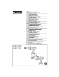
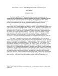
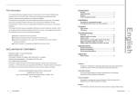
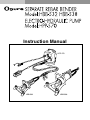
Instruction Manual
HPP-570
HBB-532
HBB-538
Read, understand and follow all safety instructions and operating
procedures. If you do not understand the instructions or if conditions are not
correct for proper operation, DO NOT OPERATE THE MACHINE. Consult
your supervisor or other responsible person.
TABLE OF CONTENTS
SAFETY INSTRUCTIONS .................................................................................................. 3
NAMES OF THE PARTS AND SPECIFICATIONS ............................................................. 5
PUMP AND BENDER SETTING UP ................................................................................... 7
ATTACHING THE POWER CORD TO PUMP .................................................................... 7
OPERATING PROCEDURE ............................................................................................... 8
SPECIAL INSTRUCTIONS FOR BENDING AND STRAIGHTENING REBAR ................ 10
ADDING OIL ..................................................................................................................... 11
WIRING DIAGRAM ........................................................................................................... 12
WARNING
Unplug power when changing tooling units, or when servicing machine.
Unplug power anytime machine is not in use.
Keep fingers away from cutting area during operation.
Never place fingers in cutting area when machine is plugged in.
Never leave machine with plug in the power source.
Check that the switch is off before plugging the machine in.
Turn off all switches in the event of a power interruption.
Metal cutting punches dies and blades have sharp edges. Handle them carefully to
avoid being cut.
Any tool can shatter. Always wear eye protection.
Seat material fully within cutting area.
Do not use the machine in damp area or where it may become wet.
Material is ejected at end of cut. Be sure that ejected slug cannot fall and cause
injury.
SAVE THESE INSTRUCTIONS
Meaning of "caution" and "warning" indications
Caution:
You may be slightly or lightly injured when you cannot avoid. This is
also used when only a physical injury is predicted to occur.
Warning:
You may die or be seriously injured when you cannot avoid.
*** Ogura & Co., Ltd. shall not be responsible for any incidental damages or
personal injuries resulting from negligence of Warnings and Safety Instructions contained in the Instruction Manual.
2
SAFETY INSTRUCTIONS
WARNING
When using electric tools, basic safety
precautions should always be followed to
reduce the risk of fire, electric shock, and
personal injury, including the following:
1. READ ALL INSTRUCTIONS
2. Power Supply
The tool should be connected only to a power supply of the same voltage as indicated on the nameplate, and can only be operated on single-phase
AC supply.
3. Grounding Instructions
3a. The double insulated model can be used
from sockets without earth wire. The models
which are not double insulated should be
grounded while in use to protect the operator
from electric shock.
3b. Extension Cords
Use only 3-wire extension cords that have 3prong grounding type plugs and 3-pole receptacles that accept the tool's plug. Replace or
repair damaged cords.
Make sure the conductor size is large enough to
prevent excessive voltage drop which will
cause loss of power and possible motor damage.
4. Replacement Parts
When servicing use only identical replacement
parts.
5. Keep Work Area Clean
Cluttered areas and benches invite injuries.
6. Consider Work Area Environment
Do not expose tool to rain.
Do not use tool in damp or wet locations.
Keep work area well lit.
Do not use tool in presence of flammable liquids
or gases.
7. Guard Against Electric Shock
Prevent body contact with grounded surfaces. For
example: pipes, radiators, ranges, refrigerator enclosures.
All visitors should be kept away from work area.
9. Store Idle Tools
When not in use, tools should be stored in a dry
and high or locked-up place - out of reach of children.
10. Do Not Force Tool
It will do the job better and safer at the rate for
which it was intended.
11. Use Right Tool
Do not force small tool or attachment to do the job
of a heavy-duty tool.
Do not use tool for purpose not intended - for example - do not use circular saw for cutting tree
limbs or logs.
12. Dress Properly
Do not wear loose clothing or jewelry. They can
be caught in moving parts. Rubber gloves and
non-skid footwear are recommended when working outdoors.
Wear protective hair covering to contain long
hair.
13. Always wear safety glasses or goggles
14. Do Not Abuse Cord
Never carry tool by cord or yank it to disconnect
from receptacle. Keep cord from heat, oil and
sharp edges.
15. Secure Work
Use clamps or a vice to hold work. It is safer than
using your hand and it frees both hands to operate tool.
16. Do Not Overreach
Keep proper footing and balance at all times.
17. Maintain Tools With Care
Keep tools sharp and clean for better and safer
performance.
Follow instructions for lubricating and changing
accessories.
Inspect tool cords periodically and, if damaged,
have repaired by authorized service facility.
Keep handles dry, clean, and free from oil and
grease.
8. Keep Children Away
Do not let visitors contact tool or extension cord.
3
Important Safety Instructions
18. Disconnect Tools
When not in use, before servicing, and when
changing accessories, such as punches and dies.
19. Remove Adjusting Keys and Wrenches
Form habit of checking to see that keys and
wrenches are removed from tool before turning it
on.
20. Outdoor Use Extension Cords
When tool is used outdoors, use only extension
cords intended for use outdoors and so marked.
21. Stay Alert
Watch what you are doing. Use common sense.
Do not operate tool when you are tired.
22. Check Damaged Parts
Before further use of the tool, a part that is damaged should be carefully checked to determine
that it will operate properly and perform its intended function. Check for alignment of moving
parts, binding of moving parts, breakage or parts,
mounting, and any other conditions that may affect
its operation. A part that is damaged should be
properly repaired or replaced by an authorized
service center unless otherwise indicated elsewhere in this instruction manual.
Have defective switches replaced by authorized
service center.
Do not use tool if switch does not turn it on and off.
23. Service at Factory Authorized Repair Center
Only
24. Operating Near Welding Equipment
When operating any grounded electrical equipment near an arc welder, it is important that both
are connected to the same earth ground. If they
are not, personal injury could result. Severe damage to the unit could also occur.
25. SAVE THESE INSTRUCTIONS
Extension Cord Gauge Selection
Length of Cord in Feet
Nameplate Ampere Rating
115V
220V
0-2
2-3
3-4
4-5
5-6
6-8
8-10
10-12
12-14
14-16
16-18
18-20
25 Ft.
50 Ft.
18
18
18
18
18
18
18
16
16
16
14
14
50 Ft.
100 Ft.
18
18
18
18
16
16
14
14
12
12
12
12
100 Ft.
200 Ft.
18
16
16
14
14
12
12
10
10
10
8
8
150 Ft.
300 Ft.
16
14
14
12
12
10
10
8
8
8
8
6
200 Ft.
400 Ft.
16
14
12
12
10
10
8
8
6
6
6
6
250 Ft.
500 Ft.
14
12
12
10
10
8
8
6
6
6
4
4
300 Ft.
600 Ft.
14
12
10
10
8
6
6
6
6
4
4
4
400 Ft. 500 Ft.
800 Ft. 1000 Ft.
12
12
10
10
10
8
8
8
8
6
6
6
6
4
4
4
4
2
4
2
2
2
2
2
ADDITIONAL SAFETY INSTRUCTIONS FOR TOOL
1. When shipped, the tool operating pressure is correctly set. Do not change this setting as excessive operating pressure is dangerous and can cause hoses and parts to fail with risk of personal injury.
2. When operating the tool, the minimum permitted bending radius for the hoses is 100mm. Operating with a
hose bending radius of less than 100mm could cause a burst hose.
3. Do not apply excessive bending forces to the hoses (especially around the coupling). If a hose is subjected
to such a force the bent part is weakened and may burst. Replace any hose that is bent or deformed.
4. Do not pull the hoses during operation as this could cause disconnection of the couplings.
5. Do not subject the hoses to external pressure as this will damage the hoses and greatly reduce the hose life.
6. Do not twist the hoses as this could cause a burst hose.
7. Do not subject the tool or hoses to excessive vibration as this could cause oil leaks or a burst hose.
4
NAME OF THE PARTS AND SPECIFICATIONS
HPP-570
Pressure Gauge (option)
Power Cord
Oil Cap
Operating Switch
Arm Set
Dust Cover (Coupling)
Cylinder
Washer
Bending Hook
Collar
HBB-532
■ ELECTRO-HYDRAULIC PUMP
Model
Weight (kg)
Dimensions Net (L ✕ W ✕ H)
Motor (single-phase)
Oil Tank Capacity
Usable Oil Capacity
Output
Hose Length
Standard Equipment
HPP-570
20.5kg
257 ✕ 257 ✕ 327.5mm
1,330W (115/230V 50/60Hz)
2.2 liters
1.0 liter (approx)
1,000cc/min
3 meters
Hydraulic oil, Carton Box
■ SEPARATE REBAR BENDER
Model
Weight (kg)
Dimensions Net (L ✕ W ✕ H)
Bending Capacity (Dia. mm)
Grade 40:
Tensile strength 490N/mm2 70,000PSI
Grade 50:
Tensile strength 560N/mm2 80,000PSI
Grade 60:
Tensile strength 620N/mm2 90,000PSI
HBB-532LT
14kg
487.5 ✕ 268.5 ✕ 181.5mm
HBB-532
16kg
438 ✕ 311 ✕ 172.5mm
HBB-538
30.9kg
509 ✕ 356 ✕ 205mm
Up to 32mm
Up to 32mm
Up to 38mm
5
Name of the Parts and Specifications
■ Standard Equipment
■ Bending Hook C (option)
HPP-570
Spare oil (#32) ..................................................................... 150cc
Plug adapter ............................................................................. 1pc
HBB-532LT, 532
Hex wrenches (8mm) ............................................................... 1pc
Spanner (24mm) ...................................................................... 1pc
Bending roller .......................................................................... 1set
*For modification of 90°inside angle
(For HBB-538,120)
HBB-538
Hex wrenches (8mm) ............................................................... 1pc
Spanner (36mm) ...................................................................... 1pc
Bending roller .......................................................................... 1set
■ Angle for Bending and Modification
Bending Angle
with Roller
HBB-532LT HBB-532
D13
D16
D19
D22
D25
D29
D32
D38
82°
78°
69°
65°
65°
82°
78°
69°
65°
65°
Bending Angle
without Roller
HBB-538 HBB-532LT HBB-532
96°
92°
89°
85°
81°
76°
90°
85°
80°
■ Bending angle
90°
85°
80°
Inside Angle of Existing Bends
Standard Hook
HBB-532LT
HBB-538
HBB-532 HBB-538
Pull modification Push modification
125°
108°
125°
134°
130°
113°
130°
136°
135°
118°
135°
138°
137°
120°
137°
141°
138°
121°
138°
143°
91°
145°
128°
145°
146°
87°
147°
130°
147°
148°
80°
154°
■ With Roller
Inside Angle
Inside Angle
(Push Bending)
(Pull Bending)
Roller
6
Roller(set)
PUMP AND BENDER SETTING UP
Before the Separate Bender can be used it should be connected
to the Ogura electro-hydraulic pump.
Pressure Gauge (option)
Coupling
CAUTION
Plug
Only use the Separate Bender with the Ogura electro-hydraulic pump provided. Use with any other pump may cause damage to components and will impair performance.
Socket
1. Connect the couplings of the two hoses from the Pump and
the Separate Bender, as shown in the drawing on the left.
After connecting each coupling, rotate the Sleeve so that the
notch is no longer in line with the Pin. This is to prevent the
coupling from being disconnected accidentally.
Sleeve
Pin
CAUTION
During use, the Pump should be placed in an upright level
position with the handle on top. If operated on a slant oil may
leak from the oil cap.
Oil Cap
2. Before use, loosen the Oil Cap on the Pump by one turn. (For
shipping and transport, the Oil Cap is tightened to avoid leaking) Loosen the Oil Cap just before starting operation and
after connecting the Pump and the Separate Bender.
CAUTION
Operating the tool without loosening the oil cap will cause large
pressure changes inside the oil tank and may result in damage to the seals and other parts.
CAUTION
Before disconnecting the hoses of the Separate Bender and
Pump, first return the Bending Rod to its starting position (fully
retracted) and then extend it about 4-5mm. After this the couplings can be disconnected. Failure to follow this procedure
may cause difficulty when the couplings are to be reconnected
because of trapped high oil pressure.
ATTACHING THE POWER CORD TO THE PUMP
Pressure Gauge (option)
Sleeve
Power Cord
Connector
1. Insert the connector of the Power Cord into the socket on the
Pump and rotate the sleeve to lock in position, as shown in
the drawing on the left. Confirm that the voltage of the power
supply is the same as the pump, 115 or 230V single phase.
Please note that, when using an extension cord there can be
a voltage drop and loss of power may occur.
2. Insert the connector of the Operation Switch into the socket
on the Pump and rotate the sleeve to lock in position, as shown
in the drawing on the left.
Operation Switch
7
OPERATING PROCEDURE
N o t e: B e f o r e o p e r a t i o n , t u r n t h e B e n d i n g H o o k
counterclockwise to confirm that the Bending Hook
is fixed securely to the Bending rod.
Bending Rod
1. Confirm that the voltage of the power supply is the same as
the voltage indicated on the name plate.
2.1 Push Bending
With the Bending Rod fully retracted, position the reinforcing
steel bar to be bent in the lower Hook of the Bending Rod.
Push the “FORWARD” button on the Operation Switch and
extend the Bending Rod to make the bend.
2.2 Pull Bending
With the Bending Rod fully extended, position the reinforcing
steel bar to be bent in the upper Hook of the Bending Rod.
Push the “BACK” button on the Operation Switch and retract
Bending Hook
Arm Set
Bending Rod
the Bending Rod to make the bend.
Note: After the bending operation is completed it will be
necessary to reverse the direction of movement of
the Bending Rod so that the reinforcing steel bar can
be removed from the tool.
✻ Rotating function of the Bending Arm Set
The Bending Arm Set with Handle can be rotated freely
through 360 degrees to achieve the best position for the
operating environment.
Bending Hook
Arm Set
2.3 To modify bends in reinforcing steel bar
To change the rebar bend angle, place the Bending Hook
over the centre of the bend in the rebar to be modified and
operate as per paras 2. and 3. above. When the inside angle
of the bend to be modified is less than the minimum angle for
the standard Hook (see Table, Page 6), the optional
Bending Hook C, which is suitable up to 90 degrees inside
angle (For HBB-538, 120 degrees), should be used.
Operation Switch
CAUTION
Ensure that the Bending Hook is placed over the top centre of
the bend to be modified. Operating with the Hook off centre
may put excessive force on the Bending Rod and Hook, resulting in damage or breakage.
Bending Hook
3. The Bending Rod will continue to move as long as the
“FORWARD” or “BACK” button is being pushed. The speed
of movement of the Bending Rod (continual or inching) is
controlled by how hard the button is pushed.
Arm Set
Rebar
8
Operating Procedure
CAUTION
To avoid damaging or breaking the Bending Hook
Push Bending
• The Bending Hook is screwed onto the Bending Rod
and together they are free to rotate. To prevent damage
to the Hook and Rod during operation ensure that the
Bending Hook is screwed firmly onto the Bending Rod.
See “Instructions for changing the Bending Hook” on this
page.
• When bending reinforcing steel bar that is fixed in Position, the tool, not being fixed, will move. Ensure that there
is enough space to allow the tool to move. If there is insufficient space and the tool contacts the floor, wall, ceiling,
etc., the excessive forces generated may damage or break
the Bending Rod. See “SPECIAL INSTRUCTION FOR
BENDING AND STRAIGHTENING REBAR” on page 10.
Pull Bending
Instruction for changing the Bending Hook
The Bending Hook, which is screwed onto the Bending
Rod, can be replaced with the optional Bending Hook C.
This is done when the inside angle of a bend to be
modified is too acute for the standard Bending Hook. The
optional Bending Hook C is suitable up to 90 degrees.
(For HBB-538, 120 degrees.)
Spanner
Bending Rod
Up
Bending Hook C
(option)
Arm Set
1. Hold the Bending Rod firmly with a spanner to prevent it
from turning and unscrew the Bending Hook in a
counter clockwise direction, to remove it from the Rod. If
it is tight it may be necessary to use a spanner or bar
through the hook to loosen it first.
2. Screw the optional Bending Hook C onto the Bending
Rod by hand in a clockwise direction until it will go no
further. Using a spanner or bar through the hook give it
a final tighten to ensure that it is fully screwed onto the
Rod.
3. With a spanner rotate the Bending Rod so that the
opening in the Bending Hook is facing up.
The Bending Hook and Bending Rod can be rotated
together. The Bending Arm Set and the Bending Rod
with Bending Hook can be turned to the best position for
the bending situation.
9
SPECIAL INSTRUCTIONS FOR BENDING AND STRAIGHTENING REBAR
To bend reinforcing steel bar that has one end
fixed to the floor, wall, ceiling, etc.
Bending
Bending Angle
B
A
Before Bending
Pull Bending
Bending Angle
B
A
Before Bending
●When bending reinforcing steel bar close to the floor, wall,
ceiling, etc., the "Pull Bending" method should be used.
When "Pull Bending", the tool will move in the direction of the
arrow and away from the surface, as shown in the drawing on
the left. Before starting, ensure that there is sufficient space
for the tool to move (see "A" and "B" in the drawing on the left
and their dimensions in the following table).
Push Bending
A
B
HBB-532LT
55mm
440mm
HBB-532
80mm
555mm
HBB-538
71mm
600mm
●When there is not enough space for "Pull Bending", the "Push
Bending" method should be used. When "Push Bending",
the tool will move in the direction of the arrow and towards
the floor, wall, or ceiling etc., as shown in the drawing on the
left. Before starting, ensure that there is sufficient space for
the tool to move (see "A" and "B" in the drawing on the left
and their dimensions in the following table).
A
B
HBB-532LT
270mm
410mm
Modifying Existing Bends
HBB-532
313mm
462mm
Standard Hook
HBB-538
336mm
518mm
To modify bend in reinforcing steel bar that
has one end fixed to the floor, wall, ceiling, etc.
The tool will move parallel to the floor, wall, ceiling, etc., as
shown in the drawing on the left. The max achievable modified
angle is shown in table on page 6.
Before Modifying
Pull Bending
Note: Up to 90 degrees of modification is possible by using
the Bending Hook C (For HBB-538, 120 degrees). but it
should be noted that the steel bar can fracture during the
bending process depending on the material of the bar.
WARNING
Operating the tool where there is insufficient space (see
table) will result in forced contact between the tool and
obstacle causing damage to the tool and Bending Rod.
Bending Hook C
WARNING
Do not bend material that is cracked or chipped as this
may cause an accident or injury to the operator.
Before Modifying
10
Pull Bending
ADDING OIL
The Pump, which is electro-hydraulic, is filled with oil when
shipped from the factory. Do not attempt to add oil as long as the
tool performs well. When the oil-pressure is not enough for the
required operation, check the oil level as follows.
Check the oil level.
Oil Gauge
The Oil Gauge Window is on the front of the Pump. If the oil
level is below the red point at the center of the window, add
the oil according to the following procedure.
Add the oil
Oil Level
Pressure Gauge (option)
Oil Cap
Open
Close
Filter
1. Unscrew and remove the Oil Cap by turning it counterclockwise.
2. Unscrew and remove the Filter by turning it counterclockwise, using the screwdriver.
3. Add oil as necessary.
4. Replace the Oil Cap and the Filter. If the tool is to be used for
further operations the Oil Cap should not be fully tightened
but set at one complete turn before the fully tightened position. This is to allow the Oil Cap to breathe so that an equal
pressure is maintained in the oil tank.
Note: For transportation, the Oil Cap should be tightened
securely to prevent any oil escape.
Note: During use, the Pump should be placed in an upright
level position with the handle on top. If operated on a
slant oil may leak from the oil cap.
NOTE: Only pure hydraulic oil as recommended by Ogura & Company Ltd. should be used in this tool. Use
Ogura supplied hydraulic oil, Super Hyrando #32 (Nippon Oil Corporation) or anti-wear hydraulic oil,
ISO Viscosity Grade 32. Do not use any other oil as this may cause damage to the gaskets and other
internal machine parts.
11
12
Re
Re
6
5
Re
Wh
1
2
Back(pull)
COB71-C9-UNKCHD20
(Forward/Back)
Switch
Bla
1 -3
Re
PF
Bl
PF
1 -4
3
7
8
Bla Wh Wh
4
Forward(push)
Gr
PM
Re
Gr
PM
F
4
4
Re
F
Re
Bl
M
Re
M
Bl
Ye
PM
Wh
Bla
PM
1 -2
1 -1
RF
Wh
Bla
RF
F
Bla
4
3
M
Bla
Ye
Push Solenoid(Right)
(W-22B-32)
Ye
Push Solenoid(Left)
(W-22B-32)
Bla
4
Motor
Bla
4
Bla
M
Bla
M
F
F
Bl
F
Wh
M
Bl
4
Bl
M
Wh
RM
2 -1
PF
Bla
S
RM
2 -2
PF
Wh
R
AC POWER
Wh
Gr
Ground
RM
2 -3
PF
Gr
WIRING DIAGRAM
MEMO
○
○
○
○
○
○
○
○
○
○
○
○
○
○
○
○
○
○
○
○
○
○
○
○
○
○
○
○
○
○
○
○
○
○
○
○
○
○
○
○
○
○
○
○
○
○
○
○
○
○
○
○
○
○
○
○
○
○
○
○
○
○
○
○
○
○
○
○
○
○
○
○
○
○
○
○
○
○
○
○
○
○
○
○
○
○
○
○
○
○
○
○
○
○
○
○
○
○
○
○
○
○
○
○
○
○
○
○
○
○
○
○
○
○
○
○
○
○
○
○
○
○
○
○
○
○
○
○
○
○
○
○
○
○
○
○
○
○
○
○
○
○
○
○
○
○
○
○
○
○
○
○
○
○
○
○
○
○
○
○
○
○
○
○
○
○
○
○
○
○
○
○
○
○
○
○
○
○
○
○
○
○
○
○
○
○
○
○
○
○
○
○
○
○
○
○
○
○
○
○
○
○
○
○
○
○
○
○
○
○
○
○
○
○
○
○
○
○
○
○
○
○
○
○
○
○
○
○
○
○
○
○
○
○
○
○
○
○
○
○
○
○
○
○
○
○
○
○
○
○
○
○
○
○
○
○
○
○
○
○
○
○
○
○
○
○
○
○
○
○
○
○
○
○
○
○
○
○
○
○
○
○
○
○
○
○
○
○
○
○
○
○
○
○
○
○
○
○
○
○
○
○
○
○
○
○
○
○
○
○
○
○
○
○
○
○
○
○
○
○
○
○
○
○
○
○
○
○
○
○
○
○
○
○
○
○
○
○
○
○
○
○
○
○
○
○
○
○
○
○
○
○
○
○
○
○
○
○
○
○
○
○
○
○
○
○
○
○
○
○
○
○
○
○
○
○
○
○
○
○
○
○
○
○
○
○
○
○
○
○
○
○
○
○
○
○
○
○
○
○
○
○
○
○
○
○
○
○
○
○
○
○
○
○
○
○
○
○
○
○
○
○
○
○
○
○
○
○
○
○
○
○
○
○
○
○
○
○
○
○
○
○
○
○
○
○
○
○
○
○
○
○
○
○
○
○
○
○
○
○
○
○
○
○
○
○
○
○
○
○
○
○
○
○
○
○
○
○
○
○
○
○
○
○
○
○
○
○
○
○
○
○
○
○
○
○
○
○
○
○
○
○
○
○
○
○
○
○
○
○
○
○
○
○
○
○
○
○
○
○
○
○
○
○
○
○
○
○
○
○
○
○
○
○
○
○
○
○
○
○
○
○
○
○
○
○
○
○
○
○
○
○
○
○
○
○
○
○
○
○
○
○
○
○
○
○
○
○
○
○
○
○
○
○
○
○
○
○
○
○
○
○
○
○
○
○
○
○
○
○
○
○
○
○
○
○
○
○
○
○
○
○
○
○
○
○
○
○
○
○
○
○
○
○
○
○
○
○
○
○
○
○
○
○
○
○
○
○
○
○
○
○
○
○
○
○
○
○
○
○
○
○
○
○
○
○
○
○
○
○
○
○
○
○
○
○
○
○
○
○
○
○
○
○
○
○
○
○
○
○
○
○
○
○
○
○
○
○
○
○
○
○
○
○
○
○
○
○
○
○
○
○
○
○
○
○
○
○
○
○
○
○
○
○
○
○
○
○
○
○
○
○
○
○
○
○
○
○
○
○
○
○
○
○
○
○
○
○
○
○
○
○
○
○
○
○
○
○
○
○
○
○
○
○
○
○
○
○
○
○
○
○
○
○
○
○
○
○
○
○
○
○
○
○
○
○
○
○
○
○
○
○
○
○
○
○
○
○
○
○
○
○
○
○
○
○
○
○
○
○
○
○
○
○
○
○
○
○
○
○
○
○
○
○
○
○
○
○
○
○
○
○
○
○
○
○
○
○
○
○
○
○
○
○
○
○
○
○
○
○
○
○
○
○
○
○
○
○
○
○
○
○
○
○
○
○
○
○
○
○
○
○
○
○
○
○
○
○
○
○
○
○
○
○
○
○
○
○
○
○
○
○
○
○
○
○
○
○
○
○
○
○
○
○
○
○
○
○
○
○
○
○
○
○
○
○
○
○
○
○
○
○
○
○
○
○
○
○
○
○
○
○
○
○
○
○
○
○
○
○
○
○
○
○
○
○
○
○
○
○
○
○
○
○
○
○
○
○
○
○
○
○
○
○
○
○
○
○
○
○
○
○
○
○
○
○
○
○
○
○
○
○
○
○
○
○
○
○
○
○
○
○
○
○
○
○
○
○
○
○
○
○
○
○
○
○
○
○
○
○
○
○
○
○
○
○
○
○
○
○
○
○
○
○
○
○
○
○
○
○
○
○
○
○
○
○
○
○
○
○
○
○
○
○
○
○
○
○
○
○
○
○
○
○
○
○
○
○
○
○
○
○
○
○
○
○
○
○
○
○
○
○
○
○
○
○
○
○
○
○
○
○
○
○
○
○
○
○
○
○
○
○
○
○
○
○
○
○
○
○
○
○
○
○
○
○
○
○
○
○
○
○
○
○
○
○
○
○
○
○
○
○
○
○
○
○
○
○
○
○
○
○
○
○
○
○
○
○
○
○
○
○
○
○
○
○
○
○
○
○
○
○
○
○
13
MEMO
14
○
○
○
○
○
○
○
○
○
○
○
○
○
○
○
○
○
○
○
○
○
○
○
○
○
○
○
○
○
○
○
○
○
○
○
○
○
○
○
○
○
○
○
○
○
○
○
○
○
○
○
○
○
○
○
○
○
○
○
○
○
○
○
○
○
○
○
○
○
○
○
○
○
○
○
○
○
○
○
○
○
○
○
○
○
○
○
○
○
○
○
○
○
○
○
○
○
○
○
○
○
○
○
○
○
○
○
○
○
○
○
○
○
○
○
○
○
○
○
○
○
○
○
○
○
○
○
○
○
○
○
○
○
○
○
○
○
○
○
○
○
○
○
○
○
○
○
○
○
○
○
○
○
○
○
○
○
○
○
○
○
○
○
○
○
○
○
○
○
○
○
○
○
○
○
○
○
○
○
○
○
○
○
○
○
○
○
○
○
○
○
○
○
○
○
○
○
○
○
○
○
○
○
○
○
○
○
○
○
○
○
○
○
○
○
○
○
○
○
○
○
○
○
○
○
○
○
○
○
○
○
○
○
○
○
○
○
○
○
○
○
○
○
○
○
○
○
○
○
○
○
○
○
○
○
○
○
○
○
○
○
○
○
○
○
○
○
○
○
○
○
○
○
○
○
○
○
○
○
○
○
○
○
○
○
○
○
○
○
○
○
○
○
○
○
○
○
○
○
○
○
○
○
○
○
○
○
○
○
○
○
○
○
○
○
○
○
○
○
○
○
○
○
○
○
○
○
○
○
○
○
○
○
○
○
○
○
○
○
○
○
○
○
○
○
○
○
○
○
○
○
○
○
○
○
○
○
○
○
○
○
○
○
○
○
○
○
○
○
○
○
○
○
○
○
○
○
○
○
○
○
○
○
○
○
○
○
○
○
○
○
○
○
○
○
○
○
○
○
○
○
○
○
○
○
○
○
○
○
○
○
○
○
○
○
○
○
○
○
○
○
○
○
○
○
○
○
○
○
○
○
○
○
○
○
○
○
○
○
○
○
○
○
○
○
○
○
○
○
○
○
○
○
○
○
○
○
○
○
○
○
○
○
○
○
○
○
○
○
○
○
○
○
○
○
○
○
○
○
○
○
○
○
○
○
○
○
○
○
○
○
○
○
○
○
○
○
○
○
○
○
○
○
○
○
○
○
○
○
○
○
○
○
○
○
○
○
○
○
○
○
○
○
○
○
○
○
○
○
○
○
○
○
○
○
○
○
○
○
○
○
○
○
○
○
○
○
○
○
○
○
○
○
○
○
○
○
○
○
○
○
○
○
○
○
○
○
○
○
○
○
○
○
○
○
○
○
○
○
○
○
○
○
○
○
○
○
○
○
○
○
○
○
○
○
○
○
○
○
○
○
○
○
○
○
○
○
○
○
○
○
○
○
○
○
○
○
○
○
○
○
○
○
○
○
○
○
○
○
○
○
○
○
○
○
○
○
○
○
○
○
○
○
○
○
○
○
○
○
○
○
○
○
○
○
○
○
○
○
○
○
○
○
○
○
○
○
○
○
○
○
○
○
○
○
○
○
○
○
○
○
○
○
○
○
○
○
○
○
○
○
○
○
○
○
○
○
○
○
○
○
○
○
○
○
○
○
○
○
○
○
○
○
○
○
○
○
○
○
○
○
○
○
○
○
○
○
○
○
○
○
○
○
○
○
○
○
○
○
○
○
○
○
○
○
○
○
○
○
○
○
○
○
○
○
○
○
○
○
○
○
○
○
○
○
○
○
○
○
○
○
○
○
○
○
○
○
○
○
○
○
○
○
○
○
○
○
○
○
○
○
○
○
○
○
○
○
○
○
○
○
○
○
○
○
○
○
○
○
○
○
○
○
○
○
○
○
○
○
○
○
○
○
○
○
○
○
○
○
○
○
○
○
○
○
○
○
○
○
○
○
○
○
○
○
○
○
○
○
○
○
○
○
○
○
○
○
○
○
○
○
○
○
○
○
○
○
○
○
○
○
○
○
○
○
○
○
○
○
○
○
○
○
○
○
○
○
○
○
○
○
○
○
○
○
○
○
○
○
○
○
○
○
○
○
○
○
○
○
○
○
○
○
○
○
○
○
○
○
○
○
○
○
○
○
○
○
○
○
○
○
○
○
○
○
○
○
○
○
○
○
○
○
○
○
○
○
○
○
○
○
○
○
○
○
○
○
○
○
○
○
○
○
○
○
○
○
○
○
○
○
○
○
○
○
○
○
○
○
○
○
○
○
○
○
○
○
○
○
○
○
○
○
○
○
○
○
○
○
○
○
○
○
○
○
○
○
○
○
○
○
○
○
○
○
○
○
○
○
○
○
○
○
○
○
○
○
○
○
○
○
○
○
○
○
○
○
○
○
○
○
○
○
○
○
○
○
○
○
○
○
○
○
○
○
○
○
○
○
○
○
○
○
○
○
○
○
○
○
○
○
○
○
○
○
○
○
○
○
○
○
○
○
○
○
○
○
○
○
○
○
○
○
○
○
○
○
○
○
○
○
○
○
○
○
○
○
○
○
○
○
○
○
○
○
○
○
○
○
○
○
○
○
○
○
○
○
○
○
○
○
○
○
○
MEMO
○
○
○
○
○
○
○
○
○
○
○
○
○
○
○
○
○
○
○
○
○
○
○
○
○
○
○
○
○
○
○
○
○
○
○
○
○
○
○
○
○
○
○
○
○
○
○
○
○
○
○
○
○
○
○
○
○
○
○
○
○
○
○
○
○
○
○
○
○
○
○
○
○
○
○
○
○
○
○
○
○
○
○
○
○
○
○
○
○
○
○
○
○
○
○
○
○
○
○
○
○
○
○
○
○
○
○
○
○
○
○
○
○
○
○
○
○
○
○
○
○
○
○
○
○
○
○
○
○
○
○
○
○
○
○
○
○
○
○
○
○
○
○
○
○
○
○
○
○
○
○
○
○
○
○
○
○
○
○
○
○
○
○
○
○
○
○
○
○
○
○
○
○
○
○
○
○
○
○
○
○
○
○
○
○
○
○
○
○
○
○
○
○
○
○
○
○
○
○
○
○
○
○
○
○
○
○
○
○
○
○
○
○
○
○
○
○
○
○
○
○
○
○
○
○
○
○
○
○
○
○
○
○
○
○
○
○
○
○
○
○
○
○
○
○
○
○
○
○
○
○
○
○
○
○
○
○
○
○
○
○
○
○
○
○
○
○
○
○
○
○
○
○
○
○
○
○
○
○
○
○
○
○
○
○
○
○
○
○
○
○
○
○
○
○
○
○
○
○
○
○
○
○
○
○
○
○
○
○
○
○
○
○
○
○
○
○
○
○
○
○
○
○
○
○
○
○
○
○
○
○
○
○
○
○
○
○
○
○
○
○
○
○
○
○
○
○
○
○
○
○
○
○
○
○
○
○
○
○
○
○
○
○
○
○
○
○
○
○
○
○
○
○
○
○
○
○
○
○
○
○
○
○
○
○
○
○
○
○
○
○
○
○
○
○
○
○
○
○
○
○
○
○
○
○
○
○
○
○
○
○
○
○
○
○
○
○
○
○
○
○
○
○
○
○
○
○
○
○
○
○
○
○
○
○
○
○
○
○
○
○
○
○
○
○
○
○
○
○
○
○
○
○
○
○
○
○
○
○
○
○
○
○
○
○
○
○
○
○
○
○
○
○
○
○
○
○
○
○
○
○
○
○
○
○
○
○
○
○
○
○
○
○
○
○
○
○
○
○
○
○
○
○
○
○
○
○
○
○
○
○
○
○
○
○
○
○
○
○
○
○
○
○
○
○
○
○
○
○
○
○
○
○
○
○
○
○
○
○
○
○
○
○
○
○
○
○
○
○
○
○
○
○
○
○
○
○
○
○
○
○
○
○
○
○
○
○
○
○
○
○
○
○
○
○
○
○
○
○
○
○
○
○
○
○
○
○
○
○
○
○
○
○
○
○
○
○
○
○
○
○
○
○
○
○
○
○
○
○
○
○
○
○
○
○
○
○
○
○
○
○
○
○
○
○
○
○
○
○
○
○
○
○
○
○
○
○
○
○
○
○
○
○
○
○
○
○
○
○
○
○
○
○
○
○
○
○
○
○
○
○
○
○
○
○
○
○
○
○
○
○
○
○
○
○
○
○
○
○
○
○
○
○
○
○
○
○
○
○
○
○
○
○
○
○
○
○
○
○
○
○
○
○
○
○
○
○
○
○
○
○
○
○
○
○
○
○
○
○
○
○
○
○
○
○
○
○
○
○
○
○
○
○
○
○
○
○
○
○
○
○
○
○
○
○
○
○
○
○
○
○
○
○
○
○
○
○
○
○
○
○
○
○
○
○
○
○
○
○
○
○
○
○
○
○
○
○
○
○
○
○
○
○
○
○
○
○
○
○
○
○
○
○
○
○
○
○
○
○
○
○
○
○
○
○
○
○
○
○
○
○
○
○
○
○
○
○
○
○
○
○
○
○
○
○
○
○
○
○
○
○
○
○
○
○
○
○
○
○
○
○
○
○
○
○
○
○
○
○
○
○
○
○
○
○
○
○
○
○
○
○
○
○
○
○
○
○
○
○
○
○
○
○
○
○
○
○
○
○
○
○
○
○
○
○
○
○
○
○
○
○
○
○
○
○
○
○
○
○
○
○
○
○
○
○
○
○
○
○
○
○
○
○
○
○
○
○
○
○
○
○
○
○
○
○
○
○
○
○
○
○
○
○
○
○
○
○
○
○
○
○
○
○
○
○
○
○
○
○
○
○
○
○
○
○
○
○
○
○
○
○
○
○
○
○
○
○
○
○
○
○
○
○
○
○
○
○
○
○
○
○
○
○
○
○
○
○
○
○
○
○
○
○
○
○
○
○
○
○
○
○
○
○
○
○
○
○
○
○
○
○
○
○
○
○
○
○
○
○
○
○
○
○
○
○
○
○
○
○
○
○
○
○
○
○
○
○
○
○
○
○
○
○
○
○
○
○
○
○
○
○
○
○
○
○
○
○
○
○
○
○
○
○
○
○
○
○
○
○
○
○
○
○
○
○
○
○
○
○
○
○
○
○
○
○
○
○
○
○
○
○
○
○
○
○
○
○
○
○
○
○
○
○
○
○
○
○
○
○
○
○
○
○
○
○
○
○
○
○
○
○
○
○
○
○
○
○
○
○
○
○
○
○
○
15
R
2661 Hongo Ebina City,
Kanagawa-pref., Japan 243-0417
TEL : 046-238-1284 FAX : 046-238-4188
IOJIN.0512