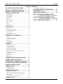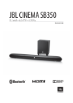
1
® Legacy Neo Battery Charger Owner's Manual To automatically be connected to your closest Service Center, call us toll-free at 1-800-DOUGLAS (1-800-368-4527) Or, visit us at: http://www.douglasbattery.com/ I.B. 1619 Rev: C (8/5/14) Model: Installed by S/N: AC Input Voltage Date IMPORTANT Read and understand your user’s manual before installing, operating, or servicing this product. DO NOT DESTROY THIS BOOK Legacy ® Neo Owner’s Manual I.B. 1619 TABLE OF CONTENTS CHARGER FAULT INDICATIONS .............................................. 15 AC LINE VOLTAGE LETTER CODES .................... 2 FLOOR MOUNTING HOLE DIMENSIONS........... 17 SPECIALTY CHARGER OPTIONS LIST ................ 2 MAINTENANCE LOG ........................................... 18 IMPORTANT SAFETY INSTRUCTIONS ................. 3 MAINTENANCE & SERVICE ................................ 19 TECHNICAL INFORMATION .................................. 4 WALL CHARGER REPLACEMENT PARTS PART NUMBER......................................................................... 4 ..................... ERROR! BOOKMARK NOT DEFINED. SERIAL NUMBER ...................................................................... 4 BATTERY TYPE ........................................................................ 4 AMPERE-HOURS ...................................................................... 4 CELLS ..................................................................................... 4 INPUT AC VOLTS..................................................................... 4 INPUT AC AMPS ...................................................................... 4 HZ ........................................................................................... 4 PHASE ..................................................................................... 4 DC VOLTS ............................................................................... 4 RATED DC AMPS ..................................................................... 4 FLOOR CHARGER REPLACEMENT PARTS ..................... ERROR! BOOKMARK NOT DEFINED. OUTPUT CABLE REPLACEMENT ...................... 22 INSTALLATION ....................................................... 5 LOCATION ............................................................................... 5 ELECTRICAL CONNECTIONS ..................................................... 5 CONNECTING INPUT POWER ..................................................... 5 AC CONNECTION ..................................................................... 5 PLUG POLARITY....................................................................... 5 GROUNDING THE CHARGER...................................................... 5 DESCRIPTION OF OPERATION............................. 6 GENERAL................................................................................. 6 CHARGER CONFIGURATION ...................................................... 6 BEGINNING THE CHARGE ......................................................... 6 CHARGING ............................................................................... 6 AC POWER FAIL ...................................................................... 6 SERIES CHARGING ................................................................... 6 GLOSSARY.............................................................. 7 CHARGING COEFFICIENT .......................................................... 7 CHARGING PROFILE ................................................................. 7 COLD STORAGE PROFILE ......................................................... 7 DESULPHATION CHARGING ...................................................... 7 EQUALIZATION CHARGING....................................................... 7 IGBT (INSULATED-GATE BIPOLAR TRANSISTOR)..................... 7 IONIC PROFILE ......................................................................... 7 NOMINAL TEMPERATURE ......................................................... 7 POWER DIODES........................................................................ 7 REFRESH ................................................................................. 7 VRLA PROFILE ....................................................................... 7 CHARGER CONFIGURATION SWITCHES ............ 8 CHARGER AMP HOUR RANGES .......................... 9 EXTERIOR WALL CABINET APPEARANCE ...... 10 EXTERIOR FLOOR CABINET APPEARANCE .... 11 OPERATING INSTRUCTIONS .............................. 12 CONTROL PANEL ................................................. 12 PUSHBUTTON ................................................................... 13 INDICATOR LIGHTS ......................................................... 13 CHARGING THE BATTERY .................................. 13 COMPLETION OF CHARGING ................................................... 14 COMPLETION OF CHARGING WITH EQUALIZATION ................... 14 MANUAL EQUALIZE WITHOUT THE MAIN CHARGE ................... 14 DESULPHATION ..................................................................... 14 CHARGE TERMINATION INDICATIONS ..................................... 15 CHARGER FAULTS .............................................. 15 1 Legacy ® Neo Owner’s Manual I.B. 1619 AC LINE VOLTAGE LETTER CODES The following table describes the code letters to be used in new charger part numbers to indicate the AC line voltage(s) and AC line frequency at which the charger can be operated. Code Letter C Y W Voltage (Volts rms.) 600 480 240 Line Frequency (Hz) 50/60 50/60 50/60 Comments Single or Three phase Single or Three phase Single or Three phase SPECIALTY CHARGER OPTIONS LIST Suffix L10 L13 L15 L18 L20 L25 Description 10' of DC cable. 13' of DC cable. 15' of DC cable. 18' of DC cable. 20' of DC cable. 25' of DC cable. 2 Legacy ® Neo Owner’s Manual I.B. 1619 IMPORTANT SAFETY INSTRUCTIONS 1. This manual contains important safety and operating instructions. Before using the battery charger, read all instructions, cautions and warnings on the battery charger, the battery and the product using the battery. 2. This charger has been designed to charge flooded lead-acid and valve-regulated lead-acid (VRLA) storage batteries. Read and understand all setup and operating instructions before using the battery charger to prevent damage to the battery and to the charger. 3. Do not touch non-insulated parts of the output connector or the battery terminals to prevent electrical shock. 4. During charge, batteries produce hydrogen gas which can explode if ignited. Never smoke, use an open flame or create sparks in the vicinity of the battery. Ventilate well when the battery is in an enclosed space. 5. Do not disconnect the battery plug while the charger is on. Doing so will cause arcing and burning of the connector resulting in charger damage or battery explosion. 6. Lead-acid batteries contain sulfuric acid which causes burns. Do not get in eyes, on skin or on clothing. In cases of contact with eyes, flush immediately with clean water for 15 minutes. Seek medical attention immediately. 7. Only the factory can service this equipment. No user serviceable parts inside. De-energize all AC and DC power connections before disconnecting the charger. 8. The charger is not for outdoor use. 9. Do not expose the charger to moisture. Operating conditions should be 0º to 104º F; 0 to 90% relative humidity. 10. Do not operate the charger if it has been dropped, received a sharp hit, or otherwise damaged in any way. 11. For continued protection and to reduce the risk of fire, install charger on a wall constructed of noncombustible material such as stone, brick or grounded metal. INSTRUCTIONS DE SÉCURITÉ IMPORTANTES 1. Ce manuel contient des informations et des consignes importantes pour l’emploi et l’utilisation du chargeur de batteries industrielles. Avant tout emploi, il est fortement conseillé de lire l’ensemble des instructions, recommandations, et avertissements concernant le chargeur et la batterie. 2. Ce chargeur est conçu pour charger inondées, scellé et TPPL plomb-acide batteries. Lire et comprendre toutes les instructions d'installation et de fonctionnement avant d'utiliser le chargeur de batterie pour éviter d'endommager la batterie et au chargeur. 3. Lisez toutes les condisnes d’installation et d’utilisation avant d’employer le chargeur de batterie pour empêcher des dommages à la batterie et / ou au chargeur. 4. Ne pas être en contact avec les pièces sous-tension non-isolées tels que la prise de charge ou des éléments de connexion de la batterie pour empêcher le choc électrique. 5. Pendant la charge, le dégagement d’hydrogène rend l’emploi de feu strictement interdit «risque d’explosion ». Ne jamais fumer, employer une flamme nue, ou créez les étincelles à proximité de la batterie. Ventiler suffisamment pour éviter toute condensation de gaz dans un espace restreint. 6. Ne brancher ou débrancher la batterie que si le chargeur est à l’arrêt. Faire ainsi risque d’endommager la prise de charge pouvant avoir pour conséquence des dommages du chargeur ou l’explosion de la batterie. 7. Les batteries d’acide au plomb contiennent l’acide sulfurique, qui cause des brûlures. Eviter le contact avec les yeux, la peau, ou sur l’habillement. Dans le cas de contact avec les yeux, et faut nettoyer immédiatement avec de l’eau propre pendant 15 minutes et consulter un médecin immédiatement. 8. Seul le personnel qualifié par l’usine peut entretenir cet équipement. Pour le service, veuillez contacter la société Douglas ou l’un de ces représentant (1-800-DOUGLAS) (1-800-368-4527) 9. Avant toute intervention d’entretien ou de réparation il faut s’assurer que le chargeur est hors tension et la batterie est déconnectée. 10. Le chargeur n’est pas pour un usage extérieur. 11. Ne pas exposer le chargeur à l’humidité. Les conditions de fonctionnement devraient être – 15° à 40°c; humidité relative de 0 à de 70%. 12. Ne pas mettre en fonctionnement le chargeur s’il a reçu un choc mécanique ou tout autre dommage di quel que façon. 13. Pour une protection permanente et pour réduire le risque du feu, installez les chargeurs sur un plancher ou un matériel non-combustible tel qu’un mur plein en béton, en brique, ou l’acier. 3 Legacy ® Neo Owner’s Manual I.B. 1619 TECHNICAL INFORMATION The nameplate, located on the outside of the charger, should be used to check this application before installation. Part Number This number specifies in general the characteristics of this particular charger and for this reason it is required in any discussion or correspondence regarding this unit. LN 3 - ECC - AH AC Model type Phase Enclosure (W=Wall or F=Floor) Number of Cells Amp Hour Rating Input Volt code Serial Number This number indicates complete information about the specific charger. It must be supplied with the part number on any correspondence or discussion regarding this charger. Battery Type The chemical content construction of the battery this unit is designed to charge is given in this part of the nameplate. (L-A = Lead-Acid) Ampere-Hours The information supplied here is the maximum ampere-hour battery capacity which this unit has been designed to charge. Charging batteries with larger ampere-hour capacities might cause the charger to deviate. Cells This portion of the nameplate gives the number of battery cells that this unit will charge. Input AC Volts The nameplate shows the input voltage accommodated by this charger. IMPORTANT: The charger will operate only on nominal line voltages stamped on the nameplate. Failure to select the correct voltage will result in damage to the charger and/or the battery. Input AC Amps The external fusing and/or the line disconnect circuit breaker should be as specified in the National Electrical Code or other local code agencies. (AC fuse values can be found on the decal inside the charger.) Hz This gives the frequency in cycles per second of the AC input voltage. Under no conditions operate charger at a different frequency or from a generator with unstable frequency. Phase Number "3" indicates a Three Phase Charger. Number "1" indicates a Single Phase Charger. DC Volts This gives the nominal DC output voltage of the system. Rated DC Amps This is the nominal DC value of current that this unit will deliver to a battery that is 100% discharged. 4 Legacy ® Neo Owner’s Manual I.B. 1619 INSTALLATION Location For maximum trouble-free service, choose a location which is free of excess moisture, dust and corrosive fumes. Also, avoid locations where temperatures are high or where liquids will drip on the charger. Allow 24 inches of clearance from the floor or the charger below, 36 inches from the ceiling and 18 inches from the sides of the charger for air circulation. Do not obstruct the ventilating openings or the space under the charger. NOTE: Ambient air temperature cannot exceed 104oF / 40oC Electrical Connections To prevent failure of the charger, be sure it is connected to the correct line voltage. On three phase units Connect the charger as follows: Phase A to L1 (fuse block) Phase B to L2 (fuse block) Phase C to L3 (fuse block) Ground to the ground lug on the charger chassis. On single phase units Connect the charger as follows: Line 1 to L1 (fuse block) Line 2 to L2 (fuse block) Ground to the ground lug on the charger chassis. Connecting Input Power WARNING: Make sure the AC power to the charger is OFF and the battery is disconnected before connecting the input power to the terminals of the charger. Connect the input power to the appropriate terminals, including ground. Follow your local electrical or National Electric Code in making these connections. AC Connection The user must provide suitable branch circuit protection and a disconnect method from the AC power supply to the charger to allow for safe operation. Plug Polarity The charging cable is connected to the DC output of the charger with the positive lead marked RED. The output polarity of the charger must be strictly observed when connecting to the battery (read warning above). Improper connection will open the DC fuse. Grounding the Charger DANGER: FAILURE TO GROUND THE CHARGER COULD LEAD TO FATAL ELECTRIC SHOCK. Follow National Electric Code for ground wire sizing. Connect a grounding conductor to the lug provided on the horizontal support panel. This lug is marked as shown: 5 Legacy ® Neo Owner’s Manual I.B. 1619 DESCRIPTION OF OPERATION General Legacy ® Neo chargers are microprocessor-controlled. In the Ionic Profile, the processor calculates the battery’s capacity so that the charging profile can be automatically adapted to the battery’s actual state over a range of capacities. The charging coefficient is maintained absolutely on all types of batteries. Legacy Neo chargers adapt to the battery’s capacity and its discharge level. As a result of our patented charging methodology, our chargers lower energy costs and extend battery life. Charging batteries used in cold storage applications with electrolyte temperatures below 68° F should use the cold storage profile selection (See Page 8). This battery charger is designed to charge flooded lead-acid and valve-regulated lead-acid (VRLA) storage batteries with a maximum ampere-hour rating and with the number of cells as marked on the nameplate. Charger Configuration The default charger configuration settings are identified on the “Charger Configuration Switches” chart on Page 8. If changes are needed, adjustments can be made by changing the configuration switches as indicated on Page 8. Beginning the Charge When a battery is connected to the charger, the control board senses voltage and after a 30 second delay, the charger energizes. Charging Charging current is determined by the battery voltage and interaction of the charger. Charging current declines automatically as battery voltage rises during the charge. When the green LED illuminates the battery is ready for service. AC Power Fail If the AC power fails with a battery connected to the charger during a charge cycle, the charger will reset and start a new charge cycle when power is restored. Series Charging In series charging, the voltages of both batteries add up and must match charger’s nameplate rating. Charger’s Ampere-Hour rating must be equal to each of the batteries Ampere-Hour rating. Charge cycle will not start unless both batteries are connected. 6 Legacy ® Neo Owner’s Manual I.B. 1619 GLOSSARY Charging Coefficient The ratio of the number of ampere-hours restored during charging to the number of ampere-hours consumed during discharge. Charging Profile The charging profile defines the rate of current charge over time. In the Ionic profile, the charger adapts to the battery’s age and level of discharge. Controlling the overcharge coefficient, whatever the battery’s discharge level, reduces the amount of electricity consumed. Cold Storage Profile In cold storage applications when a battery’s electrolyte temperature will be lower than in normal ambient temperatures, the recognized voltage of the battery will increase as electrolyte temperature decreases. This inverse relationship between battery electrolyte temperature and battery voltage will cause undercharging of the battery unless adjustments to the charge profile are made to compensate for the lower electrolyte temperatures. This charging profile is an IEI (constant current, constant voltage, constant current) type. Please refer to page 8 for information on how to change to the Cold Storage profile and to select the appropriate Battery Temperatures for your applications. The recharge range is not valid for the cold storage profile. Please contact your Douglas Representative for additional details. Desulphation Charging A desulphation charge is performed before normal charging and starts automatically on a heavily discharged battery. The desulphation charge helps to remove sulphation from the battery plates. Equalization Charging Equalization charging can be performed before or after normal charging and balances the electrolyte densities in the battery’s cells. Weekly equalization charges are required to keep the battery in peak operating condition. IGBT (Insulated-Gate Bipolar Transistor) The IGBT controls the charger output by rapidly switching the transformer primary at 20,000 to 30,000 cycles per second (Hz). Ionic Profile This is also called “ionic mixing”. This type of charging profile consists of sending short pulses of current to stimulate gas formation in the active material, causing sulphuric acid to be distributed outside the plates. This system of mixing the electrolyte enables more rapid charging of flooded cell batteries subject to very high demands and balances out differences in density, homogenizing the electrolyte across the surface of the plates. Nominal Temperature The normal temperature of the battery after an eight hour rest in the area it is used. Power Diodes The power diodes rectify the AC input and the output of the transformer. Refresh Refresh enables the battery to be maintained at maximum charge all the time that it is connected to the charger. In Ionic mode after the charge completes, the charger supplies 20 seconds of current to the battery approximately every nine minutes for as long as the battery is connected. VRLA Profile This charging profile allows for valve-regulated lead-acid batteries to be charged. This charging profile is an IEIE (constant current, constant voltage, constant current, constant voltage) type. 7 Legacy ® Neo Owner’s Manual I.B. 1619 CHARGER CONFIGURATION SWITCHES Highlighted Items are Default Value CHARGER PROFILE SELECTION Ionic (Flooded) Cold Storage – 100% Start Rate Cold Storage – 80% Start Rate Cold Storage – 65% Start Rate VRLA – 100% Start Rate VRLA – 80% Start Rate VRLA – 65% Start Rate CABLE LENGTH 8 ft. (~2.4M) 15 ft. (~4.6M) 20 ft. (~6.1M) 25 ft. (~7.6M) BATTERY TEMPERATURE 68°F - 103°F 23°F - 49°F 50°F - 67°F 104°F - 113°F EQUALIZE MODE ** Equalize Every Fifth Cycle Equalize Every Cycle SW1 OFF ON OFF ON OFF ON OFF SW4 OFF ON OFF ON SW6 OFF ON OFF ON SW8 OFF ON SW2 OFF OFF ON ON OFF OFF ON SW5 OFF OFF ON ON SW7 OFF OFF ON ON SW3 OFF OFF OFF OFF ON ON ON ** Equalize Every Fifth Cycle counts only charge cycles for DoD >= 40% toward the count target of five successfully completed Ionic Profiles. WARNING: Power must be removed and battery disconnected from the charger BEFORE changing charger configuration switches. Display Connector Switch # 1 OFF Switch # 8 OFF 8 Legacy ® Neo Owner’s Manual I.B. 1619 CHARGER AMP HOUR RANGES Highlighted Items are Default Value CHARGER AMP HOUR RANGES Ionic Cold Storage– 100% Cold Storage– 80% Cold Storage– 65% VRLA – 100% VRLA – 80% VRLA – 65% LN1-12-875 LN1-18-625 LN3-12-875 LN3-18-625 LN3-18-750 LN3-24-375 LN3-24-450 LN3-24-625 LN3-24-750 MAX 875 875 700 569 875 700 569 MAX 625 625 500 406 625 500 406 MAX 875 875 700 569 875 700 569 MAX 625 625 500 406 625 500 406 MAX 750 750 600 488 750 600 488 MAX 375 375 300 244 375 300 244 MAX 450 469 375 305 469 375 305 MAX 625 625 500 406 625 500 406 MAX 750 750 600 488 750 600 488 MIN 350 701 560 455 701 560 455 MIN 250 501 400 325 501 400 325 MIN 350 701 560 455 701 560 455 MIN 250 501 400 325 501 400 325 9 MIN 300 601 480 390 601 480 390 MIN 150 301 240 195 301 240 195 MIN 200 376 300 244 376 300 244 MIN 250 501 400 325 501 400 325 MIN 300 601 480 390 601 480 390 Legacy ® Neo Owner’s Manual I.B. 1619 EXTERIOR WALL CABINET APPEARANCE Principal components of the Legacy® Neo charger models 3 5 4 1 2 6 Ref. 1 2 3 4 5 6 Function Access door Control panel AC input cable mount Cover retaining nut Wall mounting keyholes Battery cables 10 Legacy ® Neo Owner’s Manual I.B. 1619 EXTERIOR FLOOR CABINET APPEARANCE Principal components of the Legacy ® Neo charger models 1 3 2 4 Ref. 1 2 3 4 Function Door Control panel Door lock Battery cables 11 Legacy® Neo Owner’s Manual I.B. 1619 OPERATING INSTRUCTIONS The Legacy ® Neo series of chargers are compatible with batteries of 12, 24, 36, or 48 volts (depending on the version supplied). Battery capacity and state of charge is determined automatically by the microprocessor. Three charging profiles are available (Ionic, VRLA, or Cold Storage) based on the battery design or application. Furthermore, desulphation and equalization are integrated into the charge cycle. CONTROL PANEL 1: CHARGING 2: COMPLETE 3: EQUALIZE 4: START/STOP REF 1 2 FUNCTION Red ‘Charging’ light See “Indicator Lights” for definition Green ‘Charging completed’ light (battery charged). See “Indicator Lights” for definition 3 Equalize Button - Start equalization 4 Start/Stop Button – Alternately starts and stops the charger 12 Legacy® Neo Owner’s Manual I.B. 1619 PUSHBUTTON The pushbutton has the following functions: Button <START/STOP> <EQUALIZE> Function Turns the charger on or off. When pressed with the <EQUALIZE> button, initiates a manual equalization cycle without the main charge cycle. Starts an equalize cycle at the end of charge. INDICATOR LIGHTS Light Pattern Condition Action Red & green flashing Start of the charge None. See “Charging” Red permanently lit & green unlit Normal status during charging Wait until charging is complete, indicated by the green light coming on and the red light flashing Red permanently lit & green flashing Fault Charger fault, see table “Charger Fault Indications” Red flashing & green permanently lit Charging terminated See table “Charge Termination Indications" Red unlit & green flashing Thermal interrupt (ambient temperature too high, no ventilation) or battery voltage too high or too low Check battery voltage. Charge is stopped. Check the charger’s installation and operating conditions. Red & green permanently lit Profile configuration error Check the switches configuration No mains supply Check the power supply voltage Defective power supply fuse Check the power supply voltage against the voltage accepted by the charger and the fuse Battery not connected Check that the battery and/or the battery cable is correctly connected Red and green unlit CHARGING THE BATTERY Connect the battery. The red “Charging” and green “Complete” lights flash, depending on the charging profile, as follows: Flashing alternately - Ionic (1 red/1 green) Flashing sequentially - VRLA (8 red/1 green) Flashing simultaneously - Cold Storage (red and green) After approximately 30 seconds, the red “Charging” light illuminates indicating the charge cycle has begun. If this does not happen, refer to the paragraph on “Indicator Lights”. You can stop the charge at any time by pressing the Stop/Start button. 13 Legacy® Neo Owner’s Manual I.B. 1619 Completion of charging When the green “Complete” light stays on permanently, the battery is charged and ready for use. Always push the Start/Stop button and ensure the charger is off BEFORE disconnecting the battery. If the battery remains connected, in order to keep it charged, refresh and equalization charging operations will be initiated automatically. Completion of charging with equalization An equalization charge automatically initiates after every fifth charge cycle. If desired, an equalization charge can be initiated following every charge cycle by changing the charger configuration switch 8 (SW8) to the on position. (See Page 8 “Charger Configuration Switches”) Equalization can be initiated manually by pressing the Equalize pushbutton at the end of charge. Always push the Start/Stop button and ensure the charger is off BEFORE disconnecting the battery. Manual equalize without the main charge An equalization charge can be initiated manually without the charger starting its main charge cycle. To initiate an equalize charge manually: Press the Start/Stop button to stop the charge. The two lights are unlit. Press the Equalize button while holding the Start/Stop button down. The red light illuminates and the equalization charge is initiated. At the end of charge, the “Complete” light is lit. The battery is ready for use. Always push the Start/Stop button and ensure the charger is off BEFORE disconnecting the battery. Desulphation Starts automatically when the battery is heavily discharged; the length of the desulphation operation is defined by the charger’s microprocessor. The charging process is started automatically at the end of the desulphation process. 14 Legacy® Neo Owner’s Manual I.B. 1619 Charge Termination Indications Red LED Green LED Charge Termination Condition Action Blink 1x ON IONIC Charge Completed Battery ready for use Blink 2x ON Cold Storage Charge Completed Battery ready for use Blink 3x ON VRLA Charge Completed Battery ready for use CHARGER FAULTS Should a fault condition occur, the charge cycle will be stopped, the red Charging LED will be lit and the green Complete LED will blink as detailed in the table “Charger Fault Indications”. Charger Fault Indications Red LED Green LED Charge Termination Condition Action ON Blink 1x DC Output Fault Charger is on, but not putting out expected current, check input voltage, AC fuses, and DC fuse ON Blink 3x Battery does not match charger Number of battery cells does not match charger name plate ON Blink 4x Battery overly discharged Inspect battery ON Blink 5x Current rise in phase 2 or 3 Inspect battery ON Blink 6x Charger thermal fault, occurs after 3 thermal interrupts (see table “Indicator Lights”) Check charger’s installation and operating conditions, make sure air vents are not obstructed ON Blink 8x Time limit to gassing voltage exceeded Inspect battery For service, contact the closest Service Center at: 1-800-DOUGLAS (1-800-368-4527) Or, visit us at: http://www.douglasbattery.com/ 15 Legacy® Neo Owner’s Manual I.B. 1619 Wall Mounting hole dimensions 16 Legacy® Neo Owner’s Manual I.B. 1619 FLOOR MOUNTING HOLE DIMENSIONS [mm] inches 17 Legacy® Neo Owner’s Manual I.B. 1619 MAINTENANCE LOG 1. Modifications to Factory Settings Date Variable 2. Service Date Change Description Service Technician Notes 18 Legacy® Neo Owner’s Manual I.B. 1619 MAINTENANCE & SERVICE The charger requires minimal maintenance. Connections and terminals should be kept clean and tight. The unit should be periodically cleaned with an air hose to prevent any excessive dirt build up on components. Care should be taken not to bump or move any adjustments during cleaning. Make sure that both the AC lines and the battery are disconnected before cleaning. The frequency of this type of maintenance depends on the environment in which this unit is installed. For service, contact the closest Service Center at: 1-800-DOUGLAS (1-800-368-4527) Or, visit us at: http://www.douglasbattery.com/ 19 Legacy ® Neo Owner’s Manual I.B. 1619 LN3-W12-875C LN3-W12-875Y LN3-W18-625Y LN3-W18-750C LN3-W18-750Y LN3-W24-375Y LN3-W24-450Y LN3-W24-625Y LN3-W24-750C LN3-W24-750Y PLASTIC ENCLOSURE KIT BASE/SUBASSEMBLY PANEL LED DISPLAY CARD AND RIBBON CABLE HF LOGIQ LOGO DECAL HF LOGIQ KEYPAD DECAL 160A DC FUSE 6A AC FUSE 8A AC FUSE 10A AC FUSE 12A AC FUSE 15A AC FUSE 20A AC FUSE CONFIGURED CHARGER SUB-ASSEMBLY CONFIGURED CHARGER SUB-ASSEMBLY CONFIGURED CHARGER SUB-ASSEMBLY CONFIGURED CHARGER SUB-ASSEMBLY CONFIGURED CHARGER SUB-ASSEMBLY CONFIGURED CHARGER SUB-ASSEMBLY CONFIGURED CHARGER SUB-ASSEMBLY CONFIGURED CHARGER SUB-ASSEMBLY CONFIGURED CHARGER SUB-ASSEMBLY CONFIGURED CHARGER SUB-ASSEMBLY CONFIGURED CHARGER SUB-ASSEMBLY CONFIGURED CHARGER SUB-ASSEMBLY CONFIGURED CHARGER SUB-ASSEMBLY FLOOR STAND SHELF STAND LN1-W24-625Y 019-ELLT-1 013-6LA22054 X1060-6LA11705 180-2770 180-2771 X014-09-160 X014-09-6 X014-09-8 X014-09-10 X014-09-12 X014-09-15 X014-09-20 X1100-12-875-Y1 X1100-18-625-Y1 X1100-24-625-Y1 X1100-12-875-C X1100-12-875-Y X1100-18-625-Y X1100-18-750-C X1100-18-750-Y X1100-24-375-Y X1100-24-450-Y X1100-24-625-Y X1100-24-750-C X1100-24-750-Y 390284 390285 DESCRIPTION LN1-W18-625Y PART NUMBER LN1-W12-875Y WALL CHARGER REPLACEMENT PARTS X X X X X X X X X X X X X X X X X X X X X X X X X X X X X X X X X X X X X X X X X X X X X X X X X X X X X X X X X X X X X X X X X X X X X X X X X X X X X X X X X X X X X X X X X X X X X X X X X X X X X X X X X X X X X X X FLOOR CHARGER REPLACEMENT PARTS 20 X X X X X X X X X X X X X X X X X X X Legacy ® Neo Owner’s Manual LN1-F24-625Y LN3-F12-875C LN3-F12-875Y LN3-F18-625Y LN3-F18-750C LN3-F18-750Y LN3-F24-375Y LN3-F24-450Y LN3-F24-625Y LN3-F24-750C LN3-F24-750Y DOOR BASE SUBASSEMBLY PANEL UPRIGHT PANEL SUPPORTS RIGHT SIDE EXTERIOR PANEL LEFT SIDE EXTERIOR PANEL TOP/BACK EXTERIOR PANEL LED DISPLAY CARD AND RIBBON CABLE HF LOGIQ LOGO DECAL HF LOGIQ KEYPAD DECAL 160A DC FUSE 6A AC FUSE 8A AC FUSE 10A AC FUSE 12A AC FUSE 15A AC FUSE 20A AC FUSE CONFIGURED CHARGER SUB-ASSEMBLY CONFIGURED CHARGER SUB-ASSEMBLY CONFIGURED CHARGER SUB-ASSEMBLY CONFIGURED CHARGER SUB-ASSEMBLY CONFIGURED CHARGER SUB-ASSEMBLY CONFIGURED CHARGER SUB-ASSEMBLY CONFIGURED CHARGER SUB-ASSEMBLY CONFIGURED CHARGER SUB-ASSEMBLY CONFIGURED CHARGER SUB-ASSEMBLY CONFIGURED CHARGER SUB-ASSEMBLY CONFIGURED CHARGER SUB-ASSEMBLY CONFIGURED CHARGER SUB-ASSEMBLY CONFIGURED CHARGER SUB-ASSEMBLY LN1-F18-625Y X054-HFL-1 013-99-1-1 X052-HFL-1 X052-99-0-6 X057-99-0-6 X057-99-0-7 X057-99-1-1 X1060-6LA11705 180-2770 180-2771 X014-09-160 X014-09-6 X014-09-8 X014-09-10 X014-09-12 X014-09-15 X014-09-20 X1100-12-875-Y1 X1100-18-625-Y1 X1100-24-625-Y1 X1100-12-875-C X1100-12-875-Y X1100-18-625-Y X1100-18-750-C X1100-18-750-Y X1100-24-375-Y X1100-24-450-Y X1100-24-625-Y X1100-24-750-C X1100-24-750-Y DESCRIPTION LN1-F12-875Y PART NUMBER I.B. 1619 X X X X X X X X X X X X X X X X X X X X X X X X X X X X X X X X X X X X X X X X X X X X X X X X X X X X X X X X X X X X X X X X X X X X X X X X X X X X X X X X X X X X X X X X X X X X X X X X X X X X X X X X X X X X X X X X X X X X X X X X X X X X X X X X X X X X X X X X X X X X X X X X X X X X X X X X X X X X X X X X X X X X X X X X X 21 Legacy ® Neo Owner’s Manual I.B. 1619 OUTPUT CABLE REPLACEMENT All Legacy ® Neo chargers are manufactured with gray SB175 connectors as standard. Other connectors (SB, SBX, SBE, 350 size, or Euro 160 or 320) can be specified, using established line note process. Cable gauge is restricted to #2 only. Standard length of cable is eight feet. There is an option of three other approved predetermined custom lengths with a maximum length being 25 feet. Cable Gauge #2 Replacement Cable Kits Kit for SB175 Connector Kit for SB 350 Connector X225-#2-175 X225-#2-350 Connector Housing Part Numbers PART NUMBER DESCRIPTION PART NUMBER DESCRIPTION 6325 SB175 GRAY 6320 SB350 GRAY 6326 SB175 BLUE 6321 SB350 BLUE 6329 SB175 RED 6322 SB350 RED 6328 SB175 YELLOW 6323 SB350 YELLOW 6327 SB175 ORANGE 6324 SB350 GREEN 6400 SB350 ORANGE PART NUMBER DESCRIPTION PART NUMBER DESCRIPTION 6370 SBX175 GRAY 6340 SBX350 GRAY 6371 SBX175 BLUE 6341 SBX350 BLUE 6378 SBX175 RED 6342 SBX350 RED 6373 SBX175 YELLOW 6360 SBX350 YELLOW 6387 SBX175 GREEN 6343 SBX350 GREEN 6372 SBX175 ORANGE 6359 SBX350 BLACK 6368 SBX350 ORANGE When ordering replacement cables: 1. Determine cable size and length: L10; L13; L15; L18; L20; L25 2. Determine connector housing part number. Example: For a charger requiring twenty feet (20’) of #2 AWG (gauge) cables and a SB350 RED connector, the two part numbers to order are: 1. X225-#2-350-L20 2. 6322 22 1255 Creekshire Way, Suite 221, Winston-Salem, NC 27103 1-800-DOUGLAS (1-800-368-4527) www.douglasbattery.com I.B. 1619 Rev A 7/9 ©2013 EnerSys Delaware Inc. d/b/a Douglas Battery. All Rights Reserved. Trademarks and logos are the property of EnerSys and its affiliates unless otherwise noted.