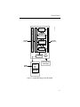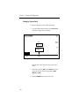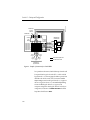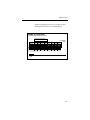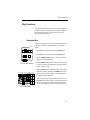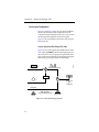
1
User Manual Grass Valley Model 4000 Digital Production Switcher Software Release 5.3 071-0162-00 First Printing: January, 1996 Revised Printing: February, 1998 Customer Support Telephone Numbers North America (800) 547-8949 Fax: (530) 478-3181 Elsewhere Distributor or sales office from which equipment was purchased. Tektronix Grass Valley Products is committed to providing the most responsive and professional product support available. We have a fully staffed, highly trained support team ready to respond to anything from a simple question to an emergency repair. Support is available via telephone or email. For new and updated customer support documents, as well as new product information, check the Tektronix web site and Grass Valley’s web page. Web Addresses Grass Valley Email Support [email protected] Grass Valley Web Page http://www.tek.com/Grass_ Valley Tektronix Web Site http://www.tek.com Postal Addresses Mail Tektronix Grass Valley Products P.O. Box 1114 Grass Valley, CA 95945 Shipping Tektronix Grass Valley Products 400 Providence Mine Rd., Nevada City, CA 95959 Copyright © Tektronix, Inc. All rights reserved. Printed in U.S.A. Tektronix products are covered by U.S. and foreign patents, issued and pending. Information in this publication supersedes that in all previously published material. Specifications and price change privileges reserved. TEKTRONIX, TEK, Grass Valley Group, Borderline, E-MEM, TEN-X, Wavelink, and are registered trademarks, and Air Link, Auto Match, Doubletake, E-Disk, Eagle V, Emphasys, EZ-Link, 409, Grass Valley, Horizon, Jogger, Kadenza, Kaleidoscope, K-Mask, Key-Layer, Key-Link, Krystal, MASTER System, Master 21, MAX, Omni-Key, Performer, Programmed Motion, Silhouette, Softset, SqueezeBack, Streamline, Super Edit, TEN-20, 20-TEN, Trace, TrailBlazer, VideoDesktop, Flex-Time, and XEDL are trademarks of Tektronix, Inc. P.O. Box 1000 Wilsonville, OR 97070-1000 U.S.A. The information in this manual is furnished for informational use only, is subject to change without notice, and should not be construed as a commitment by Tektronix, Inc. Tektronix assumes no responsibility or liability for any errors or inaccuracies that may appear in this publication. Tektronix, Inc., Video and Networking Division, P.O. Box 1114 Grass Valley, California 95945 U.S.A. Contents Preface Welcome to the Model 4000 . . . . . . . . . . . . . . . . . . . . . . . . . . . . . . . . . . . . . xi Organization of This Manual . . . . . . . . . . . . . . . . . . . . . . . . . . . . . . . . . . . . xi Related Documents . . . . . . . . . . . . . . . . . . . . . . . . . . . . . . . . . . . . . . . . . . . xii How to use this manual . . . . . . . . . . . . . . . . . . . . . . . . . . . . . . . . . . . . . . . . xii Conventions used in this manual . . . . . . . . . . . . . . . . . . . . . . . . . . . . . . . . Button References . . . . . . . . . . . . . . . . . . . . . . . . . . . . . . . . . . . . . . . . . Panel Knob References . . . . . . . . . . . . . . . . . . . . . . . . . . . . . . . . . . . . . Menu References . . . . . . . . . . . . . . . . . . . . . . . . . . . . . . . . . . . . . . . . . . Soft Button and Soft Knob References . . . . . . . . . . . . . . . . . . . . . . . . xiv xv xv xv xvi Section 1 — System Overview Basic Architecture . . . . . . . . . . . . . . . . . . . . . . . . . . . . . . . . . . . . . . . . . . . . . 1-2 Standard Features . . . . . . . . . . . . . . . . . . . . . . . . . . . . . . . . . . . . . . . . . . . . . 1-4 Optional Features . . . . . . . . . . . . . . . . . . . . . . . . . . . . . . . . . . . . . . . . . . . . . 1-5 Signal Processor Frame . . . . . . . . . . . . . . . . . . . . . . . . . . . . . . . . . . . . . 1-6 Control Panel . . . . . . . . . . . . . . . . . . . . . . . . . . . . . . . . . . . . . . . . . . . . . 1-8 Power Supplies . . . . . . . . . . . . . . . . . . . . . . . . . . . . . . . . . . . . . . . . . . 1-12 Video and Key Inputs and Outputs . . . . . . . . . . . . . . . . . . . . . . . . . 1-12 Inputs . . . . . . . . . . . . . . . . . . . . . . . . . . . . . . . . . . . . . . . . . . . . . . . 1-12 Outputs . . . . . . . . . . . . . . . . . . . . . . . . . . . . . . . . . . . . . . . . . . . . . 1-15 Functional Description . . . . . . . . . . . . . . . . . . . . . . . . . . . . . . . . . . . . . . . . 1-16 General Overview . . . . . . . . . . . . . . . . . . . . . . . . . . . . . . . . . . . . . . . . 1-16 Video Processing . . . . . . . . . . . . . . . . . . . . . . . . . . . . . . . . . . . . . . . . . 1-16 iii Contents Description of Options . . . . . . . . . . . . . . . . . . . . . . . . . . . . . . . . . . . . . . . . 1-20 Chromatte Advanced Chroma Keyer . . . . . . . . . . . . . . . . . . . . . . . . 1-20 BORDERLINE Key Edge Generation . . . . . . . . . . . . . . . . . . . . . . . . 1-20 Secondary Wipe Generator . . . . . . . . . . . . . . . . . . . . . . . . . . . . . . . . 1-20 Frame Store . . . . . . . . . . . . . . . . . . . . . . . . . . . . . . . . . . . . . . . . . . . . . . 1-21 Effects Send . . . . . . . . . . . . . . . . . . . . . . . . . . . . . . . . . . . . . . . . . . . . . . 1-21 Clean Feed . . . . . . . . . . . . . . . . . . . . . . . . . . . . . . . . . . . . . . . . . . . . . . . 1-21 Look Ahead Preview . . . . . . . . . . . . . . . . . . . . . . . . . . . . . . . . . . . . . . 1-21 Tally Relay . . . . . . . . . . . . . . . . . . . . . . . . . . . . . . . . . . . . . . . . . . . . . . 1-22 Remote Aux Bus . . . . . . . . . . . . . . . . . . . . . . . . . . . . . . . . . . . . . . . . . . 1-22 Timed Aux Output . . . . . . . . . . . . . . . . . . . . . . . . . . . . . . . . . . . . . . . 1-22 Section 2 — Startup and Configuration Powering Up . . . . . . . . . . . . . . . . . . . . . . . . . . . . . . . . . . . . . . . . . . . . . . . . . 2-1 Booting-Up . . . . . . . . . . . . . . . . . . . . . . . . . . . . . . . . . . . . . . . . . . . . . . . 2-2 Software Setup . . . . . . . . . . . . . . . . . . . . . . . . . . . . . . . . . . . . . . . . . . . . . . . . 2-2 The Configuration Menu . . . . . . . . . . . . . . . . . . . . . . . . . . . . . . . . . . . 2-2 Configuration Sub-Menus . . . . . . . . . . . . . . . . . . . . . . . . . . . . . . . 2-4 Setting User Preferences . . . . . . . . . . . . . . . . . . . . . . . . . . . . . . . . . . . . 2-9 Setting Keyer Preferences . . . . . . . . . . . . . . . . . . . . . . . . . . . . . . . . . . 2-11 Setting Preview Preferences . . . . . . . . . . . . . . . . . . . . . . . . . . . . . . . . 2-13 Beeper Preferences . . . . . . . . . . . . . . . . . . . . . . . . . . . . . . . . . . . . . . . . 2-17 Defining System Defaults . . . . . . . . . . . . . . . . . . . . . . . . . . . . . . . . . . 2-18 E-MEM Preferences . . . . . . . . . . . . . . . . . . . . . . . . . . . . . . . . . . . . . . . 2-19 Normal Mode . . . . . . . . . . . . . . . . . . . . . . . . . . . . . . . . . . . . . . . . 2-20 300 Style Mode (3-M/E Switchers Only) . . . . . . . . . . . . . . . . . 2-20 Setting System Parameters . . . . . . . . . . . . . . . . . . . . . . . . . . . . . . . . . 2-21 Using Field Dominance . . . . . . . . . . . . . . . . . . . . . . . . . . . . . . . . 2-22 Setting the System Clock . . . . . . . . . . . . . . . . . . . . . . . . . . . . . . . . . . . 2-24 Configuring Switcher Inputs . . . . . . . . . . . . . . . . . . . . . . . . . . . . . . . 2-26 Inputs . . . . . . . . . . . . . . . . . . . . . . . . . . . . . . . . . . . . . . . . . . . . . . . . . . . 2-27 Setting Analog Video Inputs . . . . . . . . . . . . . . . . . . . . . . . . . . . . . . . 2-28 Setting Analog Key Inputs . . . . . . . . . . . . . . . . . . . . . . . . . . . . . . . . . 2-29 Setting Analog Input Timing . . . . . . . . . . . . . . . . . . . . . . . . . . . . . . . 2-30 Mapping Crosspoints . . . . . . . . . . . . . . . . . . . . . . . . . . . . . . . . . . . . . 2-31 Naming Crosspoint Buttons . . . . . . . . . . . . . . . . . . . . . . . . . . . . . . . . 2-32 Formatting Chroma Key Inputs . . . . . . . . . . . . . . . . . . . . . . . . . . . . . 2-34 Assigning GPI Inputs . . . . . . . . . . . . . . . . . . . . . . . . . . . . . . . . . . . . . 2-35 Configuring Outputs . . . . . . . . . . . . . . . . . . . . . . . . . . . . . . . . . . . . . . 2-38 iv Contents Setting Output Resolution and Dither . . . . . . . . . . . . . . . . . . . . . . . Configuring External Interfaces . . . . . . . . . . . . . . . . . . . . . . . . . . . . Setting Editor Port Parameters . . . . . . . . . . . . . . . . . . . . . . . . . . . . . Configuring GPI Outputs . . . . . . . . . . . . . . . . . . . . . . . . . . . . . . . . . . DPM Configurations . . . . . . . . . . . . . . . . . . . . . . . . . . . . . . . . . . . . . . The Video Connection (Aux Buses and Return Inputs) . . . . . DPM Capabilities (Fixed and Pooled) . . . . . . . . . . . . . . . . . . . . Control Connection . . . . . . . . . . . . . . . . . . . . . . . . . . . . . . . . . . . Configuring the DPM Interface . . . . . . . . . . . . . . . . . . . . . . . . . . . . . Kaleidoscope Source Button Mapping . . . . . . . . . . . . . . . . . . . . . . . Mapping DPM Aux Buses . . . . . . . . . . . . . . . . . . . . . . . . . . . . . . . . . Example 1: Switcher-to-Kaleidoscope Configuration . . . . . . . Example 2: Switcher-to-Kaleidoscope Configuration . . . . . . . Mapping DPM Inputs . . . . . . . . . . . . . . . . . . . . . . . . . . . . . . . . . . . . . Mapping DPM Returns . . . . . . . . . . . . . . . . . . . . . . . . . . . . . . . . Configuring the Peripheral Interface . . . . . . . . . . . . . . . . . . . . . . . . Assigning Peripheral Trigger . . . . . . . . . . . . . . . . . . . . . . . . . . . Formatting Aux Buses . . . . . . . . . . . . . . . . . . . . . . . . . . . . . . . . . . . . 2-39 2-41 2-42 2-43 2-44 2-44 2-45 2-50 2-52 2-55 2-56 2-57 2-58 2-60 2-61 2-63 2-63 2-66 Section 3 — Switcher Concepts Clear Working Buffer . . . . . . . . . . . . . . . . . . . . . . . . . . . . . . . . . . . . . . . . . . 3-2 Clear Work Buffer Operation Modes . . . . . . . . . . . . . . . . . . . . . . . . . 3-3 Auto Delegation . . . . . . . . . . . . . . . . . . . . . . . . . . . . . . . . . . . . . . . . . . . . . . 3-4 Crosspoint Bus . . . . . . . . . . . . . . . . . . . . . . . . . . . . . . . . . . . . . . . . . . . . . . . 3-5 Transitions . . . . . . . . . . . . . . . . . . . . . . . . . . . . . . . . . . . . . . . . . . . . . . . . . . . Cut Transition . . . . . . . . . . . . . . . . . . . . . . . . . . . . . . . . . . . . . . . . . . . . Mix Transition . . . . . . . . . . . . . . . . . . . . . . . . . . . . . . . . . . . . . . . . . . . . Wipe Transition . . . . . . . . . . . . . . . . . . . . . . . . . . . . . . . . . . . . . . . . . . . 3-6 3-6 3-6 3-8 Keys . . . . . . . . . . . . . . . . . . . . . . . . . . . . . . . . . . . . . . . . . . . . . . . . . . . . . . . . 3-9 Luminance Key . . . . . . . . . . . . . . . . . . . . . . . . . . . . . . . . . . . . . . . . . . . 3-9 Linear Key . . . . . . . . . . . . . . . . . . . . . . . . . . . . . . . . . . . . . . . . . . . . . . . 3-11 Preset Pattern Key . . . . . . . . . . . . . . . . . . . . . . . . . . . . . . . . . . . . . . . . 3-11 Shaped and Unshaped Video . . . . . . . . . . . . . . . . . . . . . . . . . . . . . . . . . . 3-12 Input Shaped and Unshaped Video . . . . . . . . . . . . . . . . . . . . . . . . . 3-13 Output Shaped and Unshaped Video . . . . . . . . . . . . . . . . . . . . . . . 3-13 Super Black . . . . . . . . . . . . . . . . . . . . . . . . . . . . . . . . . . . . . . . . . . . . . . . . . 3-14 Chroma Key . . . . . . . . . . . . . . . . . . . . . . . . . . . . . . . . . . . . . . . . . . . . . . . . . 3-15 v Contents Coring . . . . . . . . . . . . . . . . . . . . . . . . . . . . . . . . . . . . . . . . . . . . . . . . . . . . . . 3-16 Layering . . . . . . . . . . . . . . . . . . . . . . . . . . . . . . . . . . . . . . . . . . . . . . . . . . . . 3-17 E-MEM Effects Memory . . . . . . . . . . . . . . . . . . . . . . . . . . . . . . . . . . . . . . . 3-18 Effects and Keyframes . . . . . . . . . . . . . . . . . . . . . . . . . . . . . . . . . . . . . 3-18 Enables and Delegates . . . . . . . . . . . . . . . . . . . . . . . . . . . . . . . . . . . . . 3-19 Enables and Delegates Button Tallies . . . . . . . . . . . . . . . . . . . . 3-20 Keyframing / Timelines / Effects Editing . . . . . . . . . . . . . . . . . . . . . . . 3-21 Effects Editing Definitions . . . . . . . . . . . . . . . . . . . . . . . . . . . . . . . . . 3-21 Timeline Menu . . . . . . . . . . . . . . . . . . . . . . . . . . . . . . . . . . . . . . . . . . . 3-22 Effects Send (Option) . . . . . . . . . . . . . . . . . . . . . . . . . . . . . . . . . . . . . . . . . 3-23 Frame Store (Option) . . . . . . . . . . . . . . . . . . . . . . . . . . . . . . . . . . . . . . . . . 3-24 Mask Store (Option) . . . . . . . . . . . . . . . . . . . . . . . . . . . . . . . . . . . . . . . . . . 3-25 Section 4 — Switcher Operations About this Section . . . . . . . . . . . . . . . . . . . . . . . . . . . . . . . . . . . . . . . . . . . . . 4-1 Starting Conditions . . . . . . . . . . . . . . . . . . . . . . . . . . . . . . . . . . . . . . . . . . . . 4-2 Switcher Hardware Setup . . . . . . . . . . . . . . . . . . . . . . . . . . . . . . . . . . . 4-2 Clearing the Switcher . . . . . . . . . . . . . . . . . . . . . . . . . . . . . . . . . . . . . . 4-4 Transitions - Mix/Effects Bus Operations . . . . . . . . . . . . . . . . . . . . . . . . . 4-6 Background Cut . . . . . . . . . . . . . . . . . . . . . . . . . . . . . . . . . . . . . . . . . . . 4-6 Background Mix . . . . . . . . . . . . . . . . . . . . . . . . . . . . . . . . . . . . . . . . . . . 4-9 Wipe Operations . . . . . . . . . . . . . . . . . . . . . . . . . . . . . . . . . . . . . . . . . . . . . 4-11 Background Wipe . . . . . . . . . . . . . . . . . . . . . . . . . . . . . . . . . . . . . . . . 4-11 Pattern Mixing . . . . . . . . . . . . . . . . . . . . . . . . . . . . . . . . . . . . . . . . 4-15 Learning User Wipes . . . . . . . . . . . . . . . . . . . . . . . . . . . . . . . . . . 4-16 Fade to Black . . . . . . . . . . . . . . . . . . . . . . . . . . . . . . . . . . . . . . . . . . . . . 4-19 Setting Transition Rates . . . . . . . . . . . . . . . . . . . . . . . . . . . . . . . . . . . 4-20 Background and Matte Generator Operations . . . . . . . . . . . . . . . . 4-22 Matte Selection . . . . . . . . . . . . . . . . . . . . . . . . . . . . . . . . . . . . . . . 4-22 User Defined Wash (4000-2B only) . . . . . . . . . . . . . . . . . . . . . . 4-24 Super Black . . . . . . . . . . . . . . . . . . . . . . . . . . . . . . . . . . . . . . . . . . 4-25 Luminance and Linear Keying Operations . . . . . . . . . . . . . . . . . . . . . . . 4-26 Key Transition . . . . . . . . . . . . . . . . . . . . . . . . . . . . . . . . . . . . . . . . . . . 4-31 Preset Pattern Keying Operations . . . . . . . . . . . . . . . . . . . . . . . . . . . . . . 4-32 Layered Mode Operations . . . . . . . . . . . . . . . . . . . . . . . . . . . . . . . . . . . . . 4-35 vi Contents Chroma Keying Operations . . . . . . . . . . . . . . . . . . . . . . . . . . . . . . . . . . . Auto Chroma Keying Procedure . . . . . . . . . . . . . . . . . . . . . . . . . . . . Auto Setup . . . . . . . . . . . . . . . . . . . . . . . . . . . . . . . . . . . . . . . . . . . Basic Manual Adjustment . . . . . . . . . . . . . . . . . . . . . . . . . . . . . . Optimization Adjustments . . . . . . . . . . . . . . . . . . . . . . . . . . . . . 4-36 4-37 4-39 4-40 4-41 E-MEM (Effects Memory) Operations . . . . . . . . . . . . . . . . . . . . . . . . . . . New Operational Mode Available – Version 5.1 and later . . . . . . Normal Mode . . . . . . . . . . . . . . . . . . . . . . . . . . . . . . . . . . . . . . . . Learn A Register . . . . . . . . . . . . . . . . . . . . . . . . . . . . . . . . . . . . . . Recall A Register . . . . . . . . . . . . . . . . . . . . . . . . . . . . . . . . . . . . . . 300 Style Mode – 3-M/E Switchers Only . . . . . . . . . . . . . . . . . . . . . Operational Defaults in Either Mode . . . . . . . . . . . . . . . . . . . . . . . . Setup . . . . . . . . . . . . . . . . . . . . . . . . . . . . . . . . . . . . . . . . . . . . . . . . . . . Basic E-MEM Operations . . . . . . . . . . . . . . . . . . . . . . . . . . . . . . . . . . Enabling E-MEM Register Levels . . . . . . . . . . . . . . . . . . . . . . . Learn Enables . . . . . . . . . . . . . . . . . . . . . . . . . . . . . . . . . . . . . . . . Recall Enables . . . . . . . . . . . . . . . . . . . . . . . . . . . . . . . . . . . . . . . . Storing an Effect . . . . . . . . . . . . . . . . . . . . . . . . . . . . . . . . . . . . . . Recalling an Effect . . . . . . . . . . . . . . . . . . . . . . . . . . . . . . . . . . . . Learning Effects Dissolve Transitions . . . . . . . . . . . . . . . . . . . . E-MEM Learn Sequence Operations . . . . . . . . . . . . . . . . . . . . . Undo Function . . . . . . . . . . . . . . . . . . . . . . . . . . . . . . . . . . . . . . . . . . . 4-46 4-47 4-47 4-48 4-49 4-50 4-50 4-51 4-51 4-51 4-51 4-52 4-52 4-53 4-53 4-54 4-55 Keyframe Operations . . . . . . . . . . . . . . . . . . . . . . . . . . . . . . . . . . . . . . . . . Setup . . . . . . . . . . . . . . . . . . . . . . . . . . . . . . . . . . . . . . . . . . . . . . . . . . . Basic Editing . . . . . . . . . . . . . . . . . . . . . . . . . . . . . . . . . . . . . . . . . . . . . Learn Keyframes . . . . . . . . . . . . . . . . . . . . . . . . . . . . . . . . . . . . . Advanced Keyframe Editing . . . . . . . . . . . . . . . . . . . . . . . . . . . . . . . Version 5.2 and later software changes . . . . . . . . . . . . . . . . . . . Working With Keyframe Timelines . . . . . . . . . . . . . . . . . . . . . . Setting and Adjusting Start Times . . . . . . . . . . . . . . . . . . . . . . . Zoom and Pan Timeline Effects . . . . . . . . . . . . . . . . . . . . . . . . . Cut, Copy, and Paste Keyframes . . . . . . . . . . . . . . . . . . . . . . . . Effects Editing with Get and Put . . . . . . . . . . . . . . . . . . . . . . . . Constant Duration Mode . . . . . . . . . . . . . . . . . . . . . . . . . . . . . . Using Path Types To Change An Effect . . . . . . . . . . . . . . . . . . 4-56 4-56 4-56 4-57 4-58 4-60 4-62 4-64 4-65 4-67 4-68 4-69 4-69 Effects Send Operations (Option) . . . . . . . . . . . . . . . . . . . . . . . . . . . . . . . Setup . . . . . . . . . . . . . . . . . . . . . . . . . . . . . . . . . . . . . . . . . . . . . . . . . . . Effects Send Looping Mode . . . . . . . . . . . . . . . . . . . . . . . . . . . . . . . . Effects Send Non-Looping Mode . . . . . . . . . . . . . . . . . . . . . . . . . . . 4-71 4-71 4-73 4-73 vii Contents Frame Store Operations (Option) . . . . . . . . . . . . . . . . . . . . . . . . . . . . . . . 4-74 Setup . . . . . . . . . . . . . . . . . . . . . . . . . . . . . . . . . . . . . . . . . . . . . . . . . . . 4-74 Output Routing . . . . . . . . . . . . . . . . . . . . . . . . . . . . . . . . . . . . . . . . . . 4-74 Still Image Storage . . . . . . . . . . . . . . . . . . . . . . . . . . . . . . . . . . . . . . . . 4-75 Building A Recursive Effect . . . . . . . . . . . . . . . . . . . . . . . . . . . . 4-75 Video and Key . . . . . . . . . . . . . . . . . . . . . . . . . . . . . . . . . . . . . . . . 4-76 Mask Store . . . . . . . . . . . . . . . . . . . . . . . . . . . . . . . . . . . . . . . . . . . 4-76 Freeze Mode . . . . . . . . . . . . . . . . . . . . . . . . . . . . . . . . . . . . . . . . . . . . . 4-76 Frame Store Field Modes . . . . . . . . . . . . . . . . . . . . . . . . . . . . . . . . . . 4-77 Field 1 / Field 2 . . . . . . . . . . . . . . . . . . . . . . . . . . . . . . . . . . . . . . . 4-77 Grab Field / 4 Field . . . . . . . . . . . . . . . . . . . . . . . . . . . . . . . . . . . 4-77 Mode . . . . . . . . . . . . . . . . . . . . . . . . . . . . . . . . . . . . . . . . . . . . . . . . . . . 4-77 Dropshadow Mode . . . . . . . . . . . . . . . . . . . . . . . . . . . . . . . . . . . . . . . 4-78 Repositioning . . . . . . . . . . . . . . . . . . . . . . . . . . . . . . . . . . . . . . . . . . . . 4-78 Mosaics . . . . . . . . . . . . . . . . . . . . . . . . . . . . . . . . . . . . . . . . . . . . . . . . . 4-78 Pseudo Color . . . . . . . . . . . . . . . . . . . . . . . . . . . . . . . . . . . . . . . . . . . . 4-79 Filter . . . . . . . . . . . . . . . . . . . . . . . . . . . . . . . . . . . . . . . . . . . . . . . . . . . . 4-79 Crop . . . . . . . . . . . . . . . . . . . . . . . . . . . . . . . . . . . . . . . . . . . . . . . . . . . . 4-79 Mask Store Option . . . . . . . . . . . . . . . . . . . . . . . . . . . . . . . . . . . . . . . . 4-79 Masking a Key . . . . . . . . . . . . . . . . . . . . . . . . . . . . . . . . . . . . . . . . 4-81 Softening a Mask Store Image . . . . . . . . . . . . . . . . . . . . . . . . . . 4-82 Mask Draw Option . . . . . . . . . . . . . . . . . . . . . . . . . . . . . . . . . . . . . . . 4-82 Setting up the Mask Draw . . . . . . . . . . . . . . . . . . . . . . . . . . . . . . 4-83 Mask Draw Using Key Channel . . . . . . . . . . . . . . . . . . . . . . . . . 4-84 Floppy Disk Drive Operations . . . . . . . . . . . . . . . . . . . . . . . . . . . . . . . . . 4-86 Format Diskettes . . . . . . . . . . . . . . . . . . . . . . . . . . . . . . . . . . . . . . . . . 4-86 Creating Directories and Files . . . . . . . . . . . . . . . . . . . . . . . . . . . . . . 4-87 Store and Name An E-MEM File . . . . . . . . . . . . . . . . . . . . . . . . 4-87 Store and Name A Configuration File . . . . . . . . . . . . . . . . . . . . 4-88 Loading – Recalling E-MEM Files from Disk . . . . . . . . . . . . . . 4-89 Loading (Recalling) Configuration Files from Disk . . . . . . . . 4-90 Viewing (Listing) Files and Directories . . . . . . . . . . . . . . . . . . . 4-90 Deleting Files and Directories . . . . . . . . . . . . . . . . . . . . . . . . . . . 4-91 viii Contents Appendix A — Shaped and Unshaped Video Introduction . . . . . . . . . . . . . . . . . . . . . . . . . . . . . . . . . . . . . . . . . . . . . . . . . A-1 What are Shaped and Unshaped Video? . . . . . . . . . . . . . . . . . . . . . . . . A-1 Input Shaped and Unshaped Video . . . . . . . . . . . . . . . . . . . . . . . . . . . . . A-2 Configuring the Input . . . . . . . . . . . . . . . . . . . . . . . . . . . . . . . . . . . . . A-3 Examples of Operation With Shaped & Unshaped Fill Video . . . . . . . A-4 Correct Input Configuration . . . . . . . . . . . . . . . . . . . . . . . . . . . . . . . A-6 Correct Operation With Shaped Fill Video . . . . . . . . . . . . . . . A-6 Correct Operation With Unshaped Fill Video . . . . . . . . . . . . . A-7 Incorrect Input Configuration . . . . . . . . . . . . . . . . . . . . . . . . . . . . . . A-9 Incorrect Operation With Shaped Fill Video . . . . . . . . . . . . . . A-9 Incorrect Operation With Unshaped Fill Video . . . . . . . . . . . A-10 Output Shaped and Unshaped Video . . . . . . . . . . . . . . . . . . . . . . . . . . A-13 For the Model 3000: . . . . . . . . . . . . . . . . . . . . . . . . . . . . . . . . . . A-13 For the Model 4000 or Model 2200: . . . . . . . . . . . . . . . . . . . . . A-14 Installation Considerations . . . . . . . . . . . . . . . . . . . . . . . . . . . . . . . . . . . A-16 Appendix B — Keyframe Facts Keyframe Timelines . . . . . . . . . . . . . . . . . . . . . . . . . . . . . . . . . . . . . . . . . . . B-1 Master Timeline . . . . . . . . . . . . . . . . . . . . . . . . . . . . . . . . . . . . . . . . . . . B-1 Enables and Delegates . . . . . . . . . . . . . . . . . . . . . . . . . . . . . . . . . . . . . . . . . B-2 Keyframe Path Control . . . . . . . . . . . . . . . . . . . . . . . . . . . . . . . . . . . . . . . . B-4 Tension, Continuity, and Bias Controls . . . . . . . . . . . . . . . . . . . . . . . B-4 Path Vectors . . . . . . . . . . . . . . . . . . . . . . . . . . . . . . . . . . . . . . . . . . B-5 Tension Control . . . . . . . . . . . . . . . . . . . . . . . . . . . . . . . . . . . . . . . B-6 Continuity Control . . . . . . . . . . . . . . . . . . . . . . . . . . . . . . . . . . . . . B-9 Bias Control . . . . . . . . . . . . . . . . . . . . . . . . . . . . . . . . . . . . . . . . . . B-12 ix Contents Appendix C — Super Black Definition of Super Black . . . . . . . . . . . . . . . . . . . . . . . . . . . . . . . . . . . . . . C-1 Objective . . . . . . . . . . . . . . . . . . . . . . . . . . . . . . . . . . . . . . . . . . . . . . . . . . . . C-1 Limitations . . . . . . . . . . . . . . . . . . . . . . . . . . . . . . . . . . . . . . . . . . . . . . . . . . C-1 Usage . . . . . . . . . . . . . . . . . . . . . . . . . . . . . . . . . . . . . . . . . . . . . . . . . . . . . . . C-2 Using the Super Black Output . . . . . . . . . . . . . . . . . . . . . . . . . . . . . . . . . . Generating Super Black . . . . . . . . . . . . . . . . . . . . . . . . . . . . . . . . . . . . First Method . . . . . . . . . . . . . . . . . . . . . . . . . . . . . . . . . . . . . . . . . Second Method . . . . . . . . . . . . . . . . . . . . . . . . . . . . . . . . . . . . . . . Reconstructing the Signal . . . . . . . . . . . . . . . . . . . . . . . . . . . . . . . . . . Glossary Index x C-2 C-3 C-4 C-4 C-5 Preface Welcome to the Model 4000 This manual is intended to provide you, the video switching system operator, with the information you need for operating this Digital Production Switcher. This manual, and the other manuals in this set (see Related Documents) describe these switcher models: ■ 4000-2A ■ 4000-2B ■ 4000-3 and 4000-3T (where T = Truck panel) Organization of This Manual This manual is organized as follows: Section 1, System Overview – Describes the switcher and how it is operated via the control panel. Section 2, Startup and Configuration – Describes turning on the system and verifying its operating parameters, including software configuration setups. Section 3, Switcher Concepts – Describes basic and advanced switcher operating concepts. Section 4, Switcher Operations – Step-by-step procedures on basic switcher operations. Appendices Glossary Index xi Related Documents The following manuals comprise the entire set that may be used with the Model 4000 series switcher. • Operation Reference • Installation and Service • Installation Planning Guide • Parts List • Drawings Manual • Serial Protocols Manual There are also various Options Manuals, Application Notes, Field Mod Notes, and Release Notes available for the Model 4000 and other Grass Valley products. These documents are listed on the Tektronix Grass Valley Products web page (see Customer Service Information on the back side of the Title Page) or you can contact your Grass Valley Customer Service Representative for ordering information. How To Use This Manual Begin by reading the System Overview section so that you will be familiar with the basic terminology used in this manual and the structure of the hardware/software system. Next, turn on the system as described in the Startup and Configuration section and verify the switcher parameters set up for your site or studio. It is assumed that the system has been installed according to your studio plan and that all inputs and outputs are connected properly. xii How To Use This Manual If you are an experienced switcher operator, you may choose to go directly from Startup to operating the switcher, and refer to the Control Panel Descriptions section in the Operation Reference manual only when you need to know more about the operation of a specific control. Experienced operators may also wish to refer to some parts of Section 4 — Switcher Operations, to learn about topics such as Chroma Keying, Effects Send, and how to set up keyframes (a set of switcher parameters stored in an E-MEM register). If you are not an experienced operator, you should read or scan this entire guide. You should first read Section 1 — System Overview and Section 3 — Switcher Concepts to learn switcher “basics.” Next, review the Startup and Configuration section to get a feel for the switcher setups and configurations. Finally, practice with and use the task-oriented procedures presented in the Switcher Operations section that apply to your operations on the switcher. To quickly locate specific areas of interest, refer to the “master” Table of Contents in the front of the manual, or the “local” Table of Contents located at the front of each manual section. If you have any comments about this manual, we would like to hear from you. Please write to: Tektronix, Inc. Grass Valley Products Technical Publications Department PO Box 1114 Grass Valley, CA 95945 xiii Conventions used in this manual The following graphical and typestyle conventions are used throughout this manual. The switcher model symbols shown below are located in the margin adjacent to major sections where only that model is discussed. or or symbol in the margin. xiv Conventions used in this manual Button References A control panel button is shown as follows: AUTO SETUP Panel Knob References Similarly, a control panel knob is shown as follows: LUM Menu References Many Model 4000 features may be accessed via the menu display and its associated “soft” buttons and “soft” knobs. The term “soft” means that the function of the button or knob is assigned via the currently displayed menu. An illustration similar to the following may be used for reference when you need to access a function via the menu. NOTE: The menu illustrations in the rest of this manual do not show the soft buttons and knobs in order to add clarity to the illustration. xv . Soft Knobs CHROMA KEY MENU FOREGROUND CORING = 7.50 IRE /chrKey ME 1 KEY 1 ON ON OFF ME 1 KEY 2 ON ON FIXED ME 2 KEY 1 ON ON VARIABLE ME 2 KEY 2 ON ON OFF SHADOW GAIN = 50% SHADOW CLIP = 50% VARIABLE ME 2 KEY 1 ON ON FIXED OFF OFF OFF CHR KEY FOREGROUND BACKGROUND FOREGROUND SECONDARY SELECT VIDEO VIDEO CORING COLOR > HUE MODS > KEY ADJUST > SETUP> EXIT Soft Buttons Soft Button and Soft Knob References In the text, soft buttons and soft knobs are shown in bold, using the button or knob label in the display. for example: CHR KEY SELECT SHADOW GAIN xvi — soft button — soft knob 1 System Overview This section presents a general description of the Grass Valley Group Model 4000-2A, Model 4000-2B, and 4000-3 Production Component Digital Switching Systems. The Control Panel and Signal Processor descriptions provide a basic knowledge of the Model 4000 basic architecture. All descriptions apply to all three models except when noted by either the or or symbol in the margin. 1-1 Section 1 — System Overview Basic Architecture The Model 4000 is a component digital switcher. It can manipulate CCIR 601 serial component digital and analog component video and key signals through the use of 10-bit digital processing. Video inputs and outputs can be a combination of component analog and digital bit serial depending upon the configuration of your installation and the optional input and output modules installed. The Model 4000-2A and 4000-2B provide two full function mix/effects subsystems, and a program/preset mixer. A dual (DSK 1 and DSK 2) downstream keyer (DSK) subsystem is also available. On the -2A model, the DSK is functionally similar to a mix/effect subsystem. (The DSK subsystem doesn’t have Chroma Key capability; also PGM and PST Keys do not have Fill Mattes or Border Mattes). The Model 4000-3 Switcher provides three full-function mix/effects systems and a program/preset mixer with a dual downstream keyer. The full-function control panel is designed to meet live broadcast requirements with its undelegated key bus, a separate E-MEM section for each M/E, and up to 48 video or key inputs accessed directly from the control panel crosspoints. Effects animation functionality may be used to build and run a sequence of effects. Effects are stored in E-MEM registers as a list of “keyframes” (see Section for a definition of Keyframes). The E-MEM register operations are used to learn, recall, copy, and link effect registers. 1-2 Basic Architecture Up to 64 physical external inputs may be configured. Forty-eight of these inputs may be mapped to switcher crosspoint buttons and used as video and/or key sources. Internal sources are also available, such as Black, Masks, Color Bars, and Background. The layout of the Control Panel is logically structured for efficient control of video signals.The Menu Display Subpanel allows quick changes to switcher system parameters. 1-3 Section 1 — System Overview Standard Features ■ 1-4 Mix/Effects Systems: ■ 4000-3 – Three full Mix Effects Subsystems ■ 4000 2A/2B – Two full Mix Effects Subsystems; Downstream Keyer on -2A functionally equivalent to M/E (except for Chroma Key, and no Fill or Border Mattes on PGM and PST Keys) ■ Auto-Timed Inputs ■ Shaped and Unshaped Video Input Conditioning ■ Fineline Keying ■ Unlimited Re-Entry ■ Key Channel Throughout ■ 10-Bit Data Processing Throughout ■ Full Complement of Wipe Patterns ■ E-MEM with Disk Storage ■ 100 E-MEM registers for Keyframe effects ■ Multiple-event Keyframes/Effects within a single E-MEM Register ■ User-Preference Programming ■ Safe Title/Area Generators ■ Extensive Masking ■ Complex Matte Generators ■ Analog Output Program/Preview Capability ■ Default switcher state —User defined or GVG factory setting ■ Chroma Key Autosetup Optional Features Optional Features ■ Component Digital and Analog Input Capability, up to a total of 64 inputs ■ Component Digital Output Capability ■ BORDERLINE® on all Keyers ■ Dual Chroma Keyers for each M/E ■ Second Wipe Pattern Generator for each M/E and Program/Preset ■ Kaleidoscope Run Control and Effects Recall1 ■ Four-Channel Effects Send ■ Aux Buses ■ Timed Aux Output ■ Key Outputs ■ Preview Outputs ■ Lookahead Preview, Auto Follow Preview, Push-to-Preview, and Preview Mode ■ Tally Outputs ■ DPM Port ■ Redundant Power Supplies Refer to the end of this section for descriptions of the optional features. 1. Requires a GVG Kaleidoscope DPM and the Kaleidoscope Interface Upgrade Kit (currently shipped, to customers who have purchased Kaleidoscope, with the 4.0 Software Release Package, Part No. 074825-07). 1-5 Section 1 — System Overview Physical Description The switcher consists of three main areas: the Control Panel, the Signal Processor Frame, and the Frame Power Supply (see Figure 1-1) The electronic circuitry for the Model 4000 is contained on circuit boards and modules in the Signal Processor Frame and Control Panel. Signal Processor Frame The Signal Processor Frame is a large rack-mounted unit that houses the system Controller, Mix/Effect logic and processors, Input/Output interfaces, and Expansion circuit modules. In addition to the basic system, a typical system may have several options such as Chroma Keyers, Secondary Wipe Generators, and Effects Send. Most options are available as circuit board modules (or submodules called “mezzanine” boards) to be installed in the Signal Processor Frame. Refer to the Model 4000 Installation and Service manual for a complete description of the Signal Processor. A main processor and separate M/E processors reside within the Signal Processor Frame. Since each M/E has its own processor, failure of one processor does not disable the entire switcher. Individual effects can continue to operate independently in a limited capacity. 1-6 SERIAL CROSSPOINT MATRIX ANALOG AND SERIAL INPUT MODULES Video/Key Signals In MIX EFFECTS PROCESSOR MIX EFFECTS PROCESSOR MIX EFFECTS PROCESSOR CONTROL PROCESSOR TP0625-07 EFFECTS SEND MATRIX ANALOG AND SERIALOUTPUT MODULES Optional Features Video/Key Signals Out Signal Processor Frame Processor Frame Power Supply Status Terminal CONTROL PANEL LOGIC CONTROL PANEL POWER SUPPLY Control Panel Figure 1-1. Simplified Block Diagram of the Model 4000. 1-7 Section 1 — System Overview Control Panel The Control Panel is the operator interface for the Model 4000 system. The operator performs all actions via buttons and knobs and a software-driven menu. External Interface Subpanel Frame Stores Subpanel Menu Display Subpanel Top Level Menu Buttons Grass Valley Group ® FRAME STORES EXTERNAL INTERFACE EDIT GPI PERPH DROP SHDW AUX H POSITION Floppy Disk Drive Preview/ Mask/Aux Bus FRZE V POSITION GRAB VIDEO STORE KEY STORE FIELD 1 CONFG M/E MODE KEYER CHR KEY E-MEM KEY FRAME AUX BUS MASK MATTE FRAME STORE LAST MENU MISC DISK STAT WIPE OPACITY FIELD 2 MASK STORE EXIT EFFECTS SEND PVW AUX BLACK 2 3 4 5 6 7 8 9 10 11 12 13 14 15 COLOR BKGD SHIFT SHIFT M/E 1 PGM M/E 2 PGM M/E 1 B PGM M/E 1 A M/E 1 KEY 1 M/E 1 KEY 2 M/E 2 A M/E 2 B M/E 2 KEY 1 M/E 2 KEY 2 TRANSITION KEY 1 UNCAL KEY BLACK 2 3 4 5 6 7 8 9 10 11 12 13 14 15 COLOR BKGD A BLACK 2 3 4 5 6 7 8 9 10 11 12 13 14 15 COLOR BKGD SHIFT M/E 2 UNCAL B BLACK 2 3 4 5 6 7 8 9 10 11 12 13 14 15 COLOR BKGD SHIFT M/E 2 UNCAL KEY BLACK COLOR BKGD SHIFT KEY 2 M/E 2 UNCAL EFF SEND EFF SEND BKGD B BKGD A ON ON LAYERED MIX WIPE CUT AUTO TRAN EFF SEND KEY 1 EFF SEND KEY 2 ON ON OVER OVER KEY PRIOR PST BLK 060 TRANSITION 2 3 4 5 6 7 8 9 10 11 12 13 14 15 M/E 1 KEY 1 UNCAL EFF SEND EFF SEND EFF SEND BKGD B BKGD A KEY 1 ON ON ON EFF SEND ON OVER OVER KEY 2 UNCAL A BLACK 2 3 4 5 6 7 8 9 10 11 12 13 14 15 COLOR BKGD SHIFT M/E 1 UNCAL B BLACK 2 3 4 5 6 7 8 9 10 11 12 13 14 15 COLOR BKGD SHIFT M/E 1 UNCAL DSK BLACK COLOR BKGD SHIFT PGM BLACK 2 3 4 5 6 7 8 9 10 11 12 13 14 15 COLOR BKGD PST BLACK 2 3 4 5 6 7 8 9 10 11 12 13 14 15 COLOR BKGD LAYERED KEY 2 MIX WIPE PST BLK CUT AUTO TRAN 060 KEY PRIOR 0622-101L TRANSITION 2 3 4 5 6 7 8 9 10 11 12 14 15 M/E 1 M/E 2 UNCAL SHIFT M/E 1 M/E 2 UNCAL SHIFT M/E 1 M/E 2 UNCAL BKGD DSK 1 DSK 2 ON ON OVER OVER PST BLK Source Selection 1-8 13 CUT AUTO TRAN 060 Transition Subpanels Optional Features The Control Panel also provides connectors for a status terminal and the data link to the Signal Processor Frame. Refer to Figure 1-2 Masks Subpanel MASKS TP0348-02R Wipe Subpanel WIPE SOFT TOP / GAIN SYMMETRY USER 1 USER 2 USER 3 USER 4 SOFTNESS BORD LEFT RIGHT OPACITY WIDTH ASPCT BOTTOM / CLIP MASK INV MENU ROTATION TYPE Preview/Mask/ Aux Bus (cont'd) BOX PRI WIPE SEC WIPE M/E1 KEY 1 M/E2 KEY 1 DSK 1 M/E2 KEY 2 M/E1 KEY 2 MASK BUS MASK STORE FORCE MASK INH MASK USER 5 USER 6 USER WIPE UNDO LEARN USER WIPE ROT POS ROT SPD NORM FLIP FLOP REV POSITIONER PATTERN MODIFIERS WIPE DIRECTION ROT MAG H MULTI SPLIT V MULTI POS NORM POS AUTO ROTATE DELEGATE DSK 2 M/E1 PRI WIPE PATT MIX PREVIEW ONLY M/E 2 PVW M/E1 SEC WIPE M/E2 PRI WIPE Chroma Keyers Subpanel M/E 2 SEC WIPE BUS DELEGATE DSK PVW PVW MASK KEYERS BORD SHDW EXTD AUX 1 AUX 2 AUX 3 AUX 4 MATTES PRI WIPE WASH OUT LINE SIZE / POS KEY OVER INH MASK FORCE MASK INV VIDEO FILL MATTE FILL SPLIT KEY VIDEO KEY AUTO SEL KEY LIN KEY LUM KEY CHR KEY PRI PST PTTN SEC PST PTTN KEY 1 KEY 2 HUE/ SOFTNESS FLAT MATTE SHOW KEY BKGD B BKGD A MATTE 2 R Y SHDW EXTD OUT LINE INH MASK FORCE MASK INV SHOW KEY VIDEO FILL MATTE FILL SPLIT KEY VIDEO KEY AUTO SEL KEY LIN KEY LUM KEY CHR KEY PRI PST PTTN SEC PST PTTN KEY ON BKGD B BKGD A KEY 1 KEY 2 K1 FILL SATURATION/ OFFSET GAIN INH MASK VIDEO FILL MATTE FILL LIN KEY LUM KEY KEY ON DSK 1 SHDW SPLIT KEY LUM SHADOW OPACITY CHROMA EXTD OUT LINE INV SHOW KEY VIDEO KEY AUTO SEL KEY Positioner Subpanel B K1 BORD K2 FILL K2 BORD PRI WIPE SEC WIPE HUE SHDW ON CLIP BRIGHTNESS SIZE / POS HUE/ SOFTNESS OPACITY SATURATION/ OFFSET M/E 1 KEY 1 M/E 1 KEY 2 SEC WIPE WASH FLAT MATTE MATTE 2 K1 FILL K1 BORD K2 FILL K2 BORD BRIGHTNESS SIZE / POS HUE/ SOFTNESS CLR WORK BUFR M/E 2 KEY 2 CONST DUR GET PUT RE WIND PREV NEXT GO TO TIME GO TO KF FLIP FLOP MARK BLOCK TIME ALIGN EFF DUR KF DUR REV MARK CUT COPY PASTE AUTO RUN MOD MOD EVENT INSRT BEFOR INSRT AFTER STOP NEXT KF AUTO RCL ENABLES GLOBL INHIB DPM 1 ENABL ALL M/E 1 DPM 2 MISC M/E 2 SEQ DPM 3 BKGD DPM 4 DSK PGM PST BANK SEC WIPE MATTE SEL CLIP M/E 2 KEY 1 M/E 1 PRI WIPE M/E 1 SEC WIPE M/E 2 PRI WIPE M/E 2 SEC WIPE EFFECTS MEMORY PRI WIPE WASH PRI WIPE GAIN BKGD SUPR CTR MATTE SEL DOWNSTREAM KEYERS BORD POSITIONER SELECTIVITY M MATTES BORD KEY OVER KEY OVER AUX 6 C OPACITY KEYERS NORM NORM AUX 5 CHROMA KEYERS SEC WIPE WASH G KEY ON TEXTURE PATTERN MIX M/E 1 PVW NORM RANDOM ASPECT PRESET SIZE Effects Memory (E-MEM®) Subpanel MATTES OPACITY SATURATION/ OFFSET GAIN DSK 2 USER DEF WASH SEC WIPE WASH FLAT MATTE MATTE 2 K1 FILL K1 BORD K2 FILL K2 BORD BKGD 1 BKGD 2 MATTE SEL CLIP Keyer Subpanels 8888888888888888 LOCK 7 8 9 RUN 4 5 6 BANK 0 1 2 3 BANK 1 0 TRAN RATE ENTER LRN EFF DIS UNDO • BRIGHT / TEX Matte Subpanels Figure 1-2. Model 4000-2B Control Panel 1-9 Section 1 — System Overview Grass Valley FRAME STORES EXTERNAL INTERFACE EDIT GPI PERPH CONFG M/E MODE STAT KEYER CHR KEY WIPE E-MEM KEY FRAME AUX BUS MASK MATTE FRAME STORE LAST MENU MISC DISK AUX H POSITION V POSITION OPACITY DROP SHDW FRZE VIDEO STORE PVW/AUX BLACK 2 3 FIELD 1 GRAB KEY STORE FIELD 2 MASK STORE 4 5 6 7 8 9 10 11 12 13 14 15 16 17 18 19 20 21 22 23 COLOR BKGD SHIFT M/E 1 PGM M/E 2 PGM M/E 3 PGM PGM Grass Valley Group M/E 1 M/E 2 TP0702-02L M/E 3 1-10 KEY 1 BLK 2 3 4 5 6 7 8 9 10 11 12 13 14 15 16 17 18 19 20 21 22 23 CLR BKGD SHIFT M/E 2 M/E 3 UNCAL KEY 2 BLK 2 3 4 5 6 7 8 9 10 11 12 13 14 15 16 17 18 19 20 21 22 23 CLR BKGD SHIFT M/E 2 M/E 3 UNCAL A BLACK 2 3 4 5 6 7 8 9 10 11 12 13 14 15 16 17 18 19 20 21 22 23 COLOR BKGD SHIFT M/E 2 M/E 3 UNCAL B BLACK 2 3 4 5 6 7 8 9 10 11 12 13 14 15 16 17 18 19 20 21 22 23 COLOR BKGD SHIFT M/E 2 M/E 3 UNCAL KEY 1 BLK 2 3 4 5 6 7 8 9 10 11 12 13 14 15 16 17 18 19 20 21 22 23 CLR BKGD SHIFT M/E 1 M/E 3 UNCAL KEY 2 BLK 2 3 4 5 6 7 8 9 10 11 12 13 14 15 16 17 18 19 20 21 22 23 CLR BKGD SHIFT M/E 1 M/E 3 UNCAL A BLACK 2 3 4 5 6 7 8 9 10 11 12 13 14 15 16 17 18 19 20 21 22 23 COLOR BKGD SHIFT M/E 1 M/E 3 UNCAL B BLACK 2 3 4 5 6 7 8 9 10 11 12 13 14 15 16 17 18 19 20 21 22 23 COLOR BKGD SHIFT M/E 1 M/E 3 UNCAL KEY 1 BLK 2 3 4 5 6 7 8 9 10 11 12 13 14 15 16 17 18 19 20 21 22 23 CLR BKGD SHIFT M/E 1 M/E 2 UNCAL KEY 2 BLK 2 3 4 5 6 7 8 9 10 11 12 13 14 15 16 17 18 19 20 21 22 23 CLR BKGD SHIFT M/E 1 M/E 2 UNCAL A BLACK 2 3 4 5 6 7 8 9 10 11 12 13 14 15 16 17 18 19 20 21 22 23 COLOR BKGD SHIFT M/E 1 M/E 2 UNCAL SHIFT M/E 1 M/E 2 UNCAL B BLACK 2 3 4 5 6 7 8 9 10 11 12 13 14 15 16 17 18 19 20 21 22 23 COLOR BKGD DSK 1 BLK 2 3 4 5 6 7 8 9 10 11 12 13 14 15 16 17 18 19 20 21 22 23 CLR BKGD SHIFT M/E 1 M/E 2 M/E 3 UNCAL DSK 2 BLK 2 3 4 5 6 7 8 9 10 11 12 13 14 15 16 17 18 19 20 21 22 23 CLR BKGD SHIFT M/E 1 M/E 2 M/E 3 UNCAL PROGRAM BLACK 2 3 4 5 6 7 8 9 10 11 12 13 14 15 16 17 18 19 20 21 22 23 COLOR BKGD SHIFT M/E 1 M/E 2 M/E 3 PRESET BLACK 2 3 4 5 6 7 8 9 10 11 12 13 14 15 16 17 18 19 20 21 22 23 COLOR BKGD SHIFT M/E 1 M/E 2 M/E 3 MASKS TP0702-02R Optional Features WIPE SOFT TOP / GAIN SYMMETRY USER 1 USER 2 USER 3 USER 4 SOFTNESS BORD LEFT RIGHT OPACITY WIDTH ASPCT BOTTOM / CLIP MASK INV PRESET SIZE MENU ROTATION TYPE BOX PRI WIPE SEC WIPE M/E1 KEY 1 M/E2 KEY 1 DSK 1 MASK BUS MASK STORE ROT POS FORCE MASK ROT SPD USER 5 USER 6 USER WIPE UNDO LEARN USER WIPE NORM POSITIONER PATTERN MODIFIERS WIPE DIRECTION ROT MAG FLIP FLOP REV INH MASK H MULTI SPLIT V MULTI POS NORM POS AUTO DELEGATE DSK 2 M/E2 KEY 2 TEXTURE ROTATE EXIT M/E1 KEY 2 RANDOM ASPECT M/E1 PRI WIPE PATT MIX M/E1 SEC WIPE M/E2 PRI WIPE M/E 2 SEC WIPE PATTERN MIX AUX 1-4 EFFECTS SEND ONLY M/E 1 A M/E 1 B M/E 1 KEY 1 M/E 1 KEY 2 M/E 2 B M/E 2 A M/E 2 KEY 1 BUS DELEGATE M/E 2 KEY 2 M/E 3 B M/E 3 A 88888888 7 9 8 RUN LRN EFF EFF EFF EFF BKGD B BKGD A KEY 1 KEY 2 ON ON ON 4 5 6 BANK 0 EFF DIS 1 2 3 BANK 1 0 TRAN RATE ENTER MIX BANK • PVW MASK AUX 1 A/B WIPE AUX 3 A/B AUX 4 A/B AUX 5 A/B AUX 6 A/B MATTES NORM BORD SHDW EXTD OUT LINE KEY OVER INH MASK FORCE MASK INV SHOW KEY VIDEO FILL MATTE FILL SPLIT KEY VIDEO KEY AUTO SEL KEY LIN KEY LUM KEY CHR KEY PRI PST PTTN SEC PST PTTN KEY ON BKGD B BKGD A KEY 1 KEY 2 BORDERLINE SIZE / POS KEY 1 MIX OVER PST BLK EFF AUTO TRAN CUT AUX 2 A/B KEYERS KEY 1 CUT KEY PRIOR ON OVER LAYERED SEQ UNDO M/E 3 KEY 2 TRANSITION EFFECTS MEMORY LOCK M/E 3 KEY 1 KEY 2 CUT KEY 2 MIX 888 HUE/ SOFTNESS BORDERLINE OPACITY POSITIONER PRI WIPE WASH SEC WIPE WASH FLAT MATTE MATTE 2 K1 FILL SATURATION/ OFFSET GAIN K1 BORD K2 FILL K2 BORD PRI WIPE SEC WIPE M/E 1 PRI M/E 2 PRI M/E 1 SEC M/E 2 SEC M/E 2 PRI M/E 2 SEC MATTE SEL CTR CLIP BRIGHTNESS TRANSITION EFF EFF EFF EFF BKGD B BKGD A KEY 1 KEY 2 ON ON LAYERED ON ON OVER OVER 88888888 MIX WIPE AUTO TRAN BORD SHDW EXTD OUT LINE INH MASK FORCE MASK INV SHOW KEY MATTE FILL SPLIT KEY VIDEO KEY AUTO SEL KEY BORDERLINE SIZE / POS KEY 1 MIX PST BLK EFF MATTES NORM 8 9 RUN 4 5 6 BANK 0 VIDEO FILL LRN KEY 2 CUT EFF DIS 1 KEY 2 MIX 888 7 KEY OVER LOCK SEQ CUT KEYERS EFFECTS MEMORY KEY 1 CUT KEY PRIOR UNDO BANK • 2 3 BANK 1 LIN KEY LUM KEY CHR KEY PRI PST PTTN SEC PST PTTN 0 TRAN RATE ENTER KEY ON BKGD B BKGD A KEY 1 KEY 2 HUE/ SOFTNESS CHROMA KEYERS PRI WIPE WASH SEC WIPE WASH FLAT MATTE MATTE 2 R Y SATURATION/ OFFSET GAIN K1 FILL K1 BORD K2 FILL K2 BORD PRI WIPE SEC WIPE MATTE SEL B C SHADOW OPACITY CHROMA SHDW ON M/E 1 KEY 1 CLIP LUM SELECTIVITY M G BORDERLINE OPACITY M/E 1 KEY 2 M/E 2 KEY 1 M/E 2 KEY 2 BKGD SUPR M/E 3 KEY 1 M/E 3 KEY 2 BRIGHTNESS TRANSITION EFFECTS MEMORY 88888888 LOCK 7 8 9 RUN SEQ 4 5 6 BANK 0 EFF DIS 1 2 3 BANK 1 0 TRAN RATE ENTER LRN EFF EFF EFF EFF BKGD B BKGD A KEY 1 KEY 2 ON ON LAYERED MIX UNDO BANK • CUT WIPE AUTO TRAN ON ON OVER OVER KEY 1 CUT NORM BORD SHDW EXTD OUT LINE KEY 1 MIX KEY OVER INH MASK FORCE MASK INV SHOW KEY VIDEO FILL MATTE FILL SPLIT KEY VIDEO KEY AUTO SEL KEY LIN KEY LUM KEY CHR KEY PRI PST PTTN SEC PST PTTN KEY ON BKGD B BKGD A KEY 1 KEY 2 BORDERLINE SIZE / POS PST BLK EFF MATTES KEYERS KEY PRIOR KEY 2 CUT KEY 2 MIX 888 HUE/ SOFTNESS BORDERLINE OPACITY SEC WIPE WASH FLAT MATTE MATTE 2 K1 FILL SATURATION/ OFFSET GAIN EFFECTS MEMORY PVW PRI WIPE WASH PVW PRI M/E 1 CLEAR WORK BUFR CONST DUR GET PREV NEXT GO TO TIME GO TO KF MARK BLOCK TIME ALIGN EFF DUR KF DUR K2 FILL K2 BORD PRI WIPE SEC WIPE M/E 2 M/E 3 MATTE SEL MARK CUT COPY PASTE MOD MOD EVENT INSRT BEFOR INSRT AFTER DSK CLIP BRIGHTNESS TRANSITION BKGD DSK 1 DSK 2 ON ON OVER OVER NORM BORD DSK 1 MIX KEY OVER INH MASK CUT 060 AUTO TRAN SHDW EXTD OUT LINE INV SHOW KEY BORDERLINE SIZE / POS VIDEO FILL PST BLK MATTES DOWNSTREAM KEYERS DSK 1 CUT DSK 2 CUT DSK 2 MIX MATTE FILL LIN KEY LUM KEY KEY ON DSK 1 SPLIT KEY VIDEO KEY AUTO SEL KEY PUT K1 BORD HUE/ SOFTNESS BORDERLINE OPACITY SATURATION/ OFFSET USER DEF WASH SEC WIPE WASH AUTO RCL FLAT MATTE MATTE 2 DPM 1 ENABL ALL M/E 1 LOCK DPM 2 MISC M/E 2 DPM 3 BKGD DPM 4 DSK K1 FILL K1 BORD K2 FILL K2 BORD PRI WIPE SEC WIPE GAIN MATTE SEL DSK 2 CLIP GLOBL INHIB 8888888888888888 RE WIND FLIP FLOP 7 8 9 RUN SEQ 4 5 6 BANK 0 REV M/E 3 EFF DIS 1 2 3 BANK 1 AUTO RUN PGM PST BANK 0 TRAN RATE ENTER STOP NEXT KF LRN UNDO • BRIGHT/TEX Figure 1-3. Model 4000-3 Control Panel 1-11 Section 1 — System Overview Power Supplies Two power supplies are used in the basic Model 4000 system: a control panel power supply, located in the control panel tub, and a 19 inch rack mount power supply used by the Signal Processor Frame. Optional Redundant power supplies are available. Video and Key Inputs and Outputs Inputs Three types of input modules may be installed in the Signal Processor Frame to suit the needs of your installation. The following types of input modules are available. NOTE: Each of the serial or analog inputs can be treated by the switcher as either a video input or a key input. ■ Serial Component Digital Module – provides 8 inputs, autotimed within a range of ±18 microseconds. Serial Component Digital Modules are optional in the Model 4000-2A. Up to eight modules may be installed for 64 inputs. ■ Analog Component Module – each optional Analog Component Module provides 2 analog component video inputs (RGB, YUV, Beta, or MII) and 2 analog Key inputs. Up to 8 Analog Component Modules can be installed. Every Analog Component Module is associated with a Serial Reentry Module which is included in the option set. Refer to Figure 1-4. ■ Chroma Key Input Modules–Up to 3 optional component analog Chroma Key Input Modules may be installed. Each module provides 2 inputs for a total of 6 inputs to the optional Chromatte™ Chroma Keyer. The format for each input is user-selectable from RGB, YUV, Beta or MII. Refer to the Startup section of this manual for information on assigning input formats and adjusting the timing. 1-12 Optional Features 0622-102 SERIAL DIGITAL INPUT MODULE INPUTS 1-8 CELL C16 (OPTION) SERIAL DIGITAL INPUT MODULE INPUTS 9-16 SLOT C15 (OPTION) SERIAL DIGITAL INPUT MODULE INPUTS 17-24 SLOT C14 VIDEO CROSSPOINT MATRIX (OPTION) SERIAL DIGITAL INPUT MODULE INPUTS 25-32 SLOT C13 (OPTION) ANALOG INPUT MODULES CELLS D16 AND/OR D17 SERIAL REENTRY MODULE SLOT C12 OR (OPTION) OR (OPTION) SERIAL DIGITAL INPUT MODULE INPUTS 41-48 SLOT C11 (OPTION) ANALOG INPUT MODULES CELLS D12 AND/OR D13 SERIAL REENTRY MODULE SLOT C10 OR SERIAL DIGITAL INPUT MODULE INPUTS 49-56 SLOT C10 (OPTION) (OPTION) ANALOG INPUT MODULES CELLS D10 AND/OR D11 SERIAL REENTRY MODULE SLOT C8 CHROMA KEY INPUT FORMATS: RGB YUV SMPTE BETA MII INPUTS 33-40 SLOT C12 (OPTION) ANALOG INPUT MODULES CELLS D14 AND/OR D15 SERIAL REENTRY MODULE SLOT C11 (OPTION) SERIAL DIGITAL INPUT MODULE OR SERIAL DIGITAL INPUT MODULE INPUTS 57-64 SLOT C8 (OPTION) CHROMA KEY INPUT MODULE SLOT D9 (OPTION) M/E 1 CHROMA KEYERS CHROMA KEY INPUT MODULE SLOT D8 (OPTION) CHROMA KEY INPUT MODULE SLOT D7 (OPTION) M/E 2 CHROMA KEYERS Figure 1-4. Video and Key Inputs 1-13 Section 1 — System Overview SLOT C17 SWITCHED PREVIEW 0622-103 ANALOG OUTPUT MODULE DSK PGM VIDEO (STANDARD) SERIAL DIGITAL OUTPUT MODULE MASK SLOT D6 DSK PROGRAM VIDEO SWITCHED PREVIEW DSK PROGRAM KEY M/E 1 PROGRAM VIDEO M/E 1 PROGRAM KEY/CLEAN FEED M/E 2 PROGRAM VIDEO SIGNAL PROCESSOR FRAME (STANDARD) M/E 2 PROGRAM KEY/CLEAN FEED SERIAL DIGITAL OUTPUT MODULE M/E 1 PREVIEW VIDEO SLOT D5 DSK PREVIEW VIDEO M/E 2 PREVIEW VIDEO DSK PROGRAM KEY AUX BUS 9A VIDEO AUX BUS 9B VIDEO/KEY CLEAN FEED VIDEO (OPTION) PGM/PST PREVIEW VIDEO SERIAL DIGITAL OUTPUT MODULE AUX/EFFECTS SEND BUS 1A VIDEO SLOT D4 AUX/EFFECTS SEND BUS 2A VIDEO AUX/EFFECTS SEND BUS 1B KEY AUX/EFFECTS SEND BUS 2B KEY AUX/EFFECTS SEND BUS 3A VIDEO AUX/EFFECTS SEND BUS 3B KEY AUX/EFFECTS SEND BUS 4A VIDEO (OPTION) AUX/EFFECTS SEND BUS 4B KEY SERIAL DIGITAL OUTPUT MODULE AUX BUS 5A VIDEO SLOT D3 AUX BUS 6A VIDEO AUX BUS 5B VIDEO/KEY AUX BUS 6B VIDEO/KEY AUX BUS 7A VIDEO AUX BUS 7B VIDEO/KEY AUX BUS 8A VIDEO (OPTION) AUX BUS 8B VIDEO/KEY SERIAL DIGITAL OUTPUT MODULE SLOT D2 OUTPUTS FOR FUTURE EXPANSION (OPTION) Figure 1-5. Video and Key Outputs 1-14 Optional Features Outputs Output modules are placed in both the upper and lower rear bays of the Signal Processing Frame. The following module types are available: ■ Serial Output Modules (5 optional, each adding 8 outputs each with two BNCs) ■ Analog Output Module (1 standard with RGB/Y, CR, CB and Key outputs) The standard Analog Output Module includes the following outputs: ■ DSK Program Video ■ Switched Preview Video The optional Serial Output Modules include the following outputs: ■ DSK Program Video and DSK Program Key ■ Mask Bus ■ Switched Preview Video ■ M/E 1 and M/E 2 Program Video ■ M/E 1 Program Key/Clean Feed Video (switchable) ■ M/E 2 Program Key/Clean Feed Video (switchable) ■ M/E 3 Program Key/Clean Feed Video (switchable) ■ PGM/PST Preview Video and DSK Preview Video ■ M/E 1 and M/E2 Preview Video ■ AUX Buses 1A/B--9A/B ■ Clean Feed Video 1-15 Section 1 — System Overview Functional Description General Overview Figure 1-6 shows a simple video flow diagram for the Model 4000. Video and key signals enter the input modules of the Model 4000, which consist of component analog and/or component serial digital formats. The analog signals are converted to digital format, and all inputs are timed and conditioned. The digital signals are then passed to the Video and Effects Section where keying and mixing take place. This section also provides effect modifications, such as wipes and keyframing, that can be applied to selected inputs. In the Output Section, digital video and key signals are routed to the Serial Digital Output Modules and the standard Analog Output Module before leaving the Signal Processor. Video Processing Input video and key signal selections are made by the Crosspoint Matrix under control of the system Controller, according to operator assignments entered via the Control Panel. In addition to primary (external) video, secondary (internal) sources such as Masks, M/E re-entry video, and optional Frame Store are available as inputs to the crosspoint matrix. Any suitable component digital signal from the Crosspoint matrix may feed the Chromatte™ Chroma Keyer Module option. Analog Component signals may also be used as Chroma Key sources. Keyers in each Mix/Effects bank provide outputs to the Mixer Interface crosspoints for sending outside the switcher for external processing or for routing to the M/E mixers and wipe generators. The Effects Send outputs can be directed to the Frame Store option for image capture. 1-16 Functional Description Each M/E, and the DSK, has two keyers and two background buses (A and B) as inputs. In standard mode, Keyers 1 and 2 can be mixed into a composite video and key which can be forwarded to the DSK, another M/E, or output. In layered mode, Backgrounds A and B are also used as keyers, the same as Keyers 1 and 2. Preview capability allows monitoring of sources at many points in the signal flow. You can preview video from the M/E mixers, Flip/Flop Mix and DSK mixer, switched preview bus, or mask bus. Eight level-sensitive GPI inputs are provided. You can assign each of the GPI inputs via the GPI Input menu to perform a specific function when triggered. The editor interface consists of an asynchronous RS-422, 38.4K baud serial communications port, managed by a communications processor. Refer to the Model 4000 Serial Protocols manual for information on software functions and protocols observed by the editor port. 1-17 Section 1 — System Overview Component Analog Chroma Key Inputs DUAL CHROMA KEY INPUT MODULES Video Signals In Key Signals In SERIAL DIGITAL INPUT MODULES DUAL CHROMA KEYER M/E1 & M/E2 Chr. Key 80 X 48 M/E VIDEO Video CROSSPOINT and MATRIX Key ANALOG INPUT MODULES Aux Bus 1A-4B QUAD KEYER MODULES – M/E 1 & M/E 2 Aux Bus EFFECTS SEND 1A-4B MODULES MIXER MODULE CROSSPOINTS Frame Store Video and Key M/E Program Video and Key Clocks to all modules Analog Reference Serial Digital Reference SYNC GENERATOR Clipped Mask and Mask Store Video Timing Signals to all video modules Switched Preview and Mask Black, Background 1 and 2, and Test Signals Program, Preset, and DSK Video and Key Aux Bus 5A-9B Video and Key 0622-104L CONTROL PANEL CONTROLLER (control buses not shown for clarity) 1-18 To/From All Circuits Functional Description SECONDARY WIPE OPTION 0622-104R Aux Bus 1A-4B Video and Key M/E 1 & M/E 2 MIXERS Frame Store Video and Key FRAME STORE FOR VIDEO, KEY, AND MASK STORAGE Mask Store Output Mask Store Input M/E 1 and M/E 2 Program Video and Key M/E Pvw Video SERIAL DIGITAL AND ANALOG OUTPUT MODULES Outputs (Standard and Optional) Frame Store Video and Key PREVIEW DSK Pvw Video PGM/PST MIXER AND DUAL DSK Mask and Switched Preview Program Video & Key M/E 1 and M/E 2 Program Video and Key Program Video and Key & Clean Feed Video Clean Feed Video DSK Preview Video M/E and DSK Preview Mask Switched Preview M/E1 and M/E 2 Preview DIAGNOSTIC PROBE DSK Preview NOTE: Primary Video Paths are Indicated by Wide Arrows Aux Bus Video and Key Figure 1-6. Video Flow Diagram (Typical) 1-19 Section 1 — System Overview Description of Options The following options are currently available for the Model 4000 switcher. For more details on these options, refer to the appropriate subpanel descriptions later in this manual. Chromatte Advanced Chroma Keyer Each foreground keyer in M/E 1 and M/E 2 has access to an optional component chroma keyer. Either an internal component digital signal or an external component analog signal from one of the Chroma Key Input Modules can be used as the chroma key source. Color background suppression, foreground suppression and shadow processing are included as features. BORDERLINE Key Edge Generation BORDERLINE® Key Edge Generators are available for each keyer in the switcher. The Borderline feature is implemented as a submodule that plugs onto the Keyer module of any M/E. Each Borderline generator supports 1, 2, or 3 line wide borders for border and outline modes and 1 to 6 line wide edges for shadow and extrude modes. Fill within the key edges may be either video or matte. Secondary Wipe Generator A Secondary Wipe Generator option provides a second pattern for each of the M/E systems. (On the -2A, a second pattern is available on the DSK and Program/Preset systems.) Submodules mount on the M/E 1, M/E 2, M/E 3, and DSK Mix/Wipe Modules for enhancing the mix/effect systems. 1-20 Description of Options Frame Store Using software version 5.3 and later, the Frame Store option takes the output of an M/E Keyer, sends it to the Frame Store module, then returns the output of the Frame Store to the Mix/Wipe circuit of the same M/E in the switcher. This provides the effect of inserting the Frame Store right into the M/E, between the Keyer and the Mix/Wipe systems. Effects Send Effects Send provides a method of integrating digital effects devices into the switcher mix/effects system. Up to four send channels can be used to route the video and key from an M/E to and from an external digital effects system. Clean Feed A DSK clean feed video output of the wipe/mix signals (the two background bus video signals without any keys added) is provided by one of the optional Serial Digital Output Modules. Look Ahead Preview Lookahead Preview functionality (with Auto-Follow and Push-toPreview) is provided for both M/Es with this option. Submodules mount on the M/E Mix/Wipe Modules. 1-21 Section 1 — System Overview Tally Relay The Tally Relay module provides external tally outputs that reflect the switcher status. A rear-panel interconnect board provides the relay contacts on two connectors for on-air Tally A and on-air Tally B. Pinouts for the Tally connectors are given in the Installation section of the System Information manual. Remote Aux Bus The Remote Aux Control Panel Option allows you to control the Model 4000’s aux buses from a remote location. As many as 32 Remote Aux Panels can be daisy-chained to the switcher. There are three Remote Aux Panel configurations available, identified by the number of rack units (RUs) each occupies in the equipment rack. The Models 4000-2A and 4000-3 panels are designed to control 48 external inputs (24 unshifted and 24 shifted). The Model 4000-2B panel is designed to control 32 external inputs (16 unshifted and 16 shifted). Timed Aux Output The Timed Aux Output Module provides four independent output pairs (video/key) from aux buses 5A through 8B for use with Kaleidoscope and DPM systems. 1-22 2 Startup and Configuration This section describes turning on the system, setting up user preferences, and setting up system parameters. Powering Up The Model 4000 is designed for continuous operation. Use the following procedures to power-up the switcher when it has been turned off. 1. Turn the power switch on the front of the Signal Processor Power Supply to the ON position. Verify that the power supply voltage LEDs on the front of the Power Supply are lit and that the fans in the Processor are on. 2. Raise the Control Panel and turn the power supply switch to the ON position. Verify that the green RUN LED on the CPU Board (located in the middle of the tub) is lit. 3. Verify that the Model 4000 sign-on logo is displayed on the Menu Display. 4. Verify that the panel pushbutton lamps are on and that the E-MEM and Transition subpanel readout LEDs are on. If any of the above conditions are not present, turn the system power off and refer to the Diagnostics and Troubleshooting section in the Installation and Service manual. 2-1 Section 2— Startup and Configuration Booting-Up When the system is turned on, the switcher will initialize into a defined default state. This default state may be either a userdefined default or a GVG factory default of switcher enabled levels, as selected in the Define Defaults Menu (see Section 3, Model 4000 Operation Reference manual). Software Setup The system parameters to be used at your site are usually configured following installation of the equipment. Use the following procedures to configure the 4000 system to your installation. In addition to assigning sources, the process includes setting configuring inputs, output levels, external interfaces, and system parameters. These functions are accessed via the Control Panel Configuration Menu sub-menus (see Figures 2-1, 2-2, and 2-3, Parts 1 through 3). The Configuration Menu The Configuration Menu is a top-level menu which provides access to the User Preferences, System Parameters, Inputs, Outputs, External Interface, and Aux Bus Formats sub-menus. 2-2 Software Setup CONFIGURATION MENU /config USER PREFS > SYSTEM PARAM > INPUTS > OUTPUTS > EXTERN I/F > AUX BUS FORMATS> To begin the setup process, press the CONFG button on the Menu Display Subpanel to display the Configuration Menu and the submenu choices. ■ USER PREFS > — Set up operating parameters, such as Keyer and Preview preferences and default switcher states. ■ SYSTEM PARAMS > — Set aspect ratio, the matte generator limiter and the system clock. ■ INPUTS > — Define your inputs and name crosspoint buttons. ■ OUTPUTS > — Adjust the luminance and chroma limiter settings on the switcher outputs. ■ EXTERN I/F > — Select or change settings for the Editor, DPM, and Peripherals Interfaces connected to the Model 4000. ■ AUX BUS FORMAT > —Sets the “B” Aux Bus on Aux buses 5B– 9B to be either a separate video or key bus to accompany the corresponding “A” Aux Bus. Set Aux Buses 1 through 4 (physical/logical) for shaped or unshaped video output. 2-3 Section 2— Startup and Configuration Configuration Sub-Menus USER PREFERENCES ■ Keyer Prefs ■ Preview Prefs ■ Beeper Prefs ■ Define Defaults ■ E-MEM Prefs SYSTEM PARAMETERS ■ Aspect Ratio ■ Matte Gen Lim ■ Set Clock Menus (Date /Time) INPUTS MENUS 2-4 ■ Analog Video Inputs ■ Analog Key Inputs ■ Analog Input Timing ■ Map Inputs and Name Crosspoint Button ■ Chroma Key Inputs ■ GPI Inputs Software Setup OUTPUTS MENU ■ Output Digital Resolution Menu EXTERNAL INTERFACE MENUS ■ Editor I/F ■ DPM I/F ■ Peripheral I/F ■ GPI Outputs AUX BUS FORMAT MENU ■ Aux Bus Shaping 2-5 Section 2— Startup and Configuration LATCH NORMAL CLEAR KEY MEM SHIFT MODE KEYER PREFS PREVIEW PREFS BEEPER PREFS E-MEM PREFS DEFINE DEFAULTS CONFG (Part 1) M/E 1 M/E 2 PGM PST PVW SELECT PVW MODE DIM PVW PUSH TO PVW ON OFF RUN LEVER KEYFRAME EDITING MASTER E-MEM ENABLE/DISABLE ENABLE/DISABLE 4X3 See CONFG Part 3 † NOTE: Some soft knob adjustments have been omitted for clarity. Figure 2-1. Configuration Menu Tree (Part 1 of 3) 2-6 ALL KEYERS DELEG KEYER OFF M/E 1 M/E 2 M/E 3 M/E SELECT GVG DEFAULT SET DEFAULT ASPECT RATIO FIELD DOMINANCE SET CLOCK MATTE GEN LIM PUSH TO PVW TIMEOUT 300 STYLE/NORMAL (3 M/E only) Software Version 5.1 See CONFG Part 2 AUTO LOOKAHEAD PGM ON/OFF ON/OFF ON/OFF ON/OFF ON/OFF BEEPER ON/OFF WARNING END OF KNOB KNOB CENTER INACTIVE KNOB USER PREFS SYSTEM PARAM INPUTS OUTPUTS EXTERN I/F AUX BUS FORMAT CLEAR XPT CLEAR BUS CLEAR SECT CLEAR SWCHR SECTION SELECT BUS SELECT 0764-00 (PT 1) ON OFF ON OFF DSK DROP KEY MEMORY 16 X 9 SELECT CONFIRM FIELD 1 FIELD 2 NONE DATE — TIME — XMITABLE VALID RGB BOTH NONE YEAR HOUR MONTH MINUTE DAY SECOND CARD SELECT INP n FORMAT INP n SETUP INP n FORMAT INP n SETUP CARDS 1– 8 (INPUTS 33–64) RGB BETA RGB YUV BETA MII ON/OFF YUV MII ON/OFF CARD SELECT INP n SETUP INP n SETUP See CONFG Part 1 CONFG (Part 2) CARD SELECT INP n TIMING INP n TIMING ANLG VIDEO INPUTS ANLG KEY INPUTS ANLG INPUT TIMING MAP INPUTS CHR KEY INPUTS GPI INPUTS USER PREFS SYSTEM PARAM INPUTS OUTPUTS EXTERN I/F AUX BUS FORMAT TOP TEST SIGNAL BOTTOM TEST SIGNAL VIDEO/KEY FORMAT LOG PHYS INPUTS NAME XPT BUTTON VIDEO INPUT KEY INPUT CHROMA KEY INPUT Software Version 5.1 See CONFG Part 3 INPUT 1 INPUT 2 INPUT 3 INPUT 4 INPUT 5 INPUT 6 SETUP INPUT FORMAT GPI SELECT MISC KF EFFECT AUTO TRANS CUT E-MEM FRAME STORE PROGRAM GPI † NOTE: Some soft knob adjustments have been omitted for clarity. 0764-00(PT 2) Software Setup CARDS 1– 8 (INPUTS 33–64) NO SETUP KEY SETUP CARDS 1– 8 (INPUTS 33–64) 1–4 1–4 UNSHAPED VIDEO SHAPED VIDEO LOG CHANNEL PHYS INPUTS CURSOR BACK ACCEPT CHAR CURSOR FORWRD DELETE CHAR SAVE STRING GET STRING ACCEPT NAME COARSE TIMING FINE TIMING ON/OFF RGB BETA YUV MII GPI 1 GPI 2 GPI 3 GPI 4 GPI 5 GPI 6 GPI 7 GPI 8 AUX TALLY LOG CHAN TALLY DISABLE GPI RUN REWIND AUTO RUN REVERSE M/E1 M/E2 M/E3 PGM PST PGM PST PST BLACK M/E1 M/E2 M/E3 PGM PST VIDEO GRAB KEY GRAB MASK GRAB RECALL M/E1 RECALL M/E2 RECALL M/E3 RECALL MASTER AUTO RCL EFF DISSSOLV SEQUENCE Figure 2-2. Configuration Menu Tree (Part 2 of 3) 2-7 10 BIT/ON OUTPUT SELECT RESOLUTION/DITHER OUTPUT SELECT RESOLUTION/DITHER DIGITAL RES OUTPUT SELECT LUM LIMITER CHROMA LIMITER M/E 1 PGM M/E 2 PGM M/E 3 PGM DSK PGM DSK CLEAN AUX 1 AUX 2 AUX 3 AUX 4 10 BIT/OFF 8 BIT/ON 8 BIT/OFF PGM ME1 PGM ME2 PGM ME3 PGM 10 BIT/OFF M/E 1 PVW 8 BIT/ON M/E 2 PVW M/E 3 PVW PEAK WHITE PEAK BLACK BOTH OFF See CONFG Part 2 DSK PVW DSK DIRTY PEAK OFF See CONFG Part 1 0764-00(PT 3) Section 2— Startup and Configuration DPM 1 DPM 2 2400 4800 9600 19200 38400 BAUD PARITY CONFG (Part 3) USER PREFS SYSTEM PARAM INPUTS OUTPUTS EXTERN I/F AUX BUS FORMAT DPM 3 DPM 4 KSCOPE KRYSTAL ODD EVEN NONE OTHER FIXED NONE DEVICE SELECT SWTCHR XPT BUTTON SE DPM TYPE EDITOR I/F DPM I/F PERIPHERAL I/F GPI OUTPUTS K'SCOPE SOURCES SET DEFAULTS CHANNEL ROUTING SWR IN DPM MAP AUX BUS SWR OUT DPM MAP INPUTS BOTH Software Version 5.1 OFF EFF SEND DELAY DPM 2 DEVICE SELECT NO. OF CHANNELS BAUD PARITY PERIPH TRIGGER CHAN 1 = AUX ... CHANNEL SELECT KEY INPUT DEVICE NO. FUNCTION NO. LEVEL ASSIGN MISC FIRE DPM 1 DPM 2 OFF DPM 3 GPI 1-8 GPI 1-8 E-MEM LEVEL DPM 4 MISC DPM 1 DPM 2 GPI LENGTH DPM 3 DPM 4 AUX 5B AUX 6B AUX 7B AUX 8B AUX 9B AUX BUS SHAPING VIDEO KEY AUX 1 AUX 2 AUX 3 PHYS AUX SELECT UNSHAPER AUX 4 ON OFF Figure 2-3. Configuration Menu Tree (Part 3 of 3) 2-8 CHAN A-H AUX 1-9 DPM 4 DPM 1 DPM 3 DPM 4 VIDEO INPUT TRIGGER SELECT (A THRU H) SELECT GPI DPM 3 DPM 2 DPM SELECT ODD EVEN NONE PGM CUT TRIGGER SWITCHER BUTTON. DPM 1 CONTROL DELAY 2400 4800 9600 19200 38400 K'SCOPE BUTTON A, B, C, D, E, F, G, H Software Setup Setting User Preferences Use the User Preferences Menus to gain access to keyer, preview, and switcher defaults submenus. 1. From the Configuration Menu, press the USER PREFS > button to access the User Preferences Menu. USER PREFS MENU config/user prefs LATCH NORMAL SHIFT MODE KEYER PREFS > PREVIEW PREFS > BEEPER PREFS > DEFINE DEFAULTS > E-MEM PREFS > 2-9 Section 2— Startup and Configuration 2. Select either LATCH or NORMAL with the SHIFT MODE soft button. The LATCH selection allows you to lock any switcher crosspoint bus into a shifted (UPPERCASE) state. This allows ready access to those input sources mapped to shifted crosspoints. (See “Configuring Switcher Inputs” on page 2-26.) With LATCH enabled on the User Preferences Menu, press and hold the SHIFT button while selecting a crosspoint. The bus containing that crosspoint is now locked into a shifted state. Any crosspoint selected on this bus will now be a shifted crosspoint. The SHIFT button light will remain ON while the bus is in this state. To unshift a bus, press and hold the SHIFT button. Select a crosspoint button. The bus is now unshifted, and the SHIFT button lamp is OFF. 3. 2-10 Select the KEYER PREFS > submenu. Software Setup Setting Keyer Preferences From the User Preferences Menu, press the KEYER PREFS> button to display the Keyer Preferences Menu: KEYER PREFS MENU config/user prefs/keyer prefs ON ON OFF OFF DSK DROP KEY MEMORY CLEAR KEY MEM> 1. The DSK DROP button allows you to enable or disable DSK Drop mode. DSK Drop mode ON drops any DSK when a program bus crosspoint is pressed. (This is usually left OFF.) 2. The KEY MEMORY Button allows you to turn on or off the key memory feature. ON enables crosspoints to remember all key settings. (This is usually left ON.) 2-11 Section 2— Startup and Configuration 3. Press CLEAR KEY MEMORY to invoke the Clear Key Memory Menu. CLEAR KEY MEMORY MENU config / user prefs / keyer prefs / clear key mem CURRENT XPT 7 Press a button below to clear key memory for – M/E 1 M/E 2 DSK AUX MASK A B KEY 1 KEY 2 SECTION SELECT BUS SELECT CLEAR XPT: the current xpt on the selected bus CLEAR BUS: all xpts on the selected bus CLEAR SECTION: all xpts on all buses in the selected section CLEAR SWITCHER: all xpts in the switcher CLEAR XPT CLEAR BUS CLEAR SECTION CLEAR SWITCHER This menu allows you to clear the key memory settings for various areas of the switcher. 4. With the SECTION SELECT and BUS SELECT buttons, select the area of the switcher whose key memory you wish to clear. To select a specific crosspoint on a bus: After selecting the section and bus, press the specific crosspoint on the selected bus. (The number of that crosspoint will appear in the CURRENT XPT box in the menu.) 2-12 5. Use the CLEAR XPT, CLEAR BUS, CLEAR SECTION, or CLEAR SWITCHER button to clear the desired memory area. 6. Press EXIT to return to the User Preferences Menu. Software Setup Setting Preview Preferences From the User Preferences Menu, press the PREVIEW PREFS> button to display the Preview Preferences Menu. NOTE: It is important to note that these menu setups affect only the PVW output connectors and the PVW Monitor(s). PREVIEW PREFS MENU PUSH TO PREVIEW TIMEOUT = 3 secs config/user prefs/preview prefs M/E 1 M/E 2 PGM/PST PGM ALL KEYERS LOOKAHEAD PGM AUTO OFF OFF ALL KEYERS LOOKAHEAD DELEG KEYER M/E 2 PGM OFF PVW SELECT PVW MODE DIM PVW ON OFF PUSH TO PVW 1. Use the PVW SELECT button to select the switcher subsystem; M/E 1, M/E 2, or PGM PST, that you wish to set preview options for. 2. Use the PVW MODE button to select the preview mode desired for the selected switcher subsystem: 2-13 Section 2— Startup and Configuration NOTE: The optional M/E Preview Mezzanine must be installed for each M/E in order to select AUTO and LOOKAHEAD Preview Modes. These selections will not be displayed in the menu if the mezzanine board is not installed. The Preview Mode choice depends on how many monitors you have per M/E, and how you wish to use them (see Figure 2-2). AUTO – Use this mode to automatically toggle between PGM and PVW (next transition) when a single M/E monitor is used. A high tally on the M/E displays PVW output. A low tally on the M/E displays PGM output. LOOKAHEAD – Use to review what is going on-air next. Always shows the next transition of the selected M/E. PGM – Use this selection to have the PGM output of the M/E or PGM/DSK displayed on the Preview monitor. (Useful if your PGM monitor goes down — signal is feed from the switched PVW output. KEY PVW – (Displayed when PGM/PST is selected.) Previews DSK 1 and DSK 2 keys over the PGM/PST transition on the Preview Monitor. 2-14 Software Setup M/E 2 PGM Out PGM M/E 2 PVW Out PVW Switcher Fixed Lookahead 2 Monitors per M/E Switcher PVW Out PGM Out - Low Tally AUTO Lookahead - Hi Tally 1 Monitor per M/E Switcher PVW Out PGM Fixed PGM (In effect, no PVW function enabled.) 1 Monitor per M/E Figure 2-4. Preview Mode Configurations 2-15 Section 2— Startup and Configuration 3. Use the DIM PVW button to dim the preview of all keyers using a mask in that M/E or PGM/DSK, or to turn off the preview dim function so that the preview never dims regardless of masking. 4. Assign a Dim Preview mode to one of the following: ALL KEYERS – the preview of all keyers using a mask in that M/E or DSK will dim the Preview monitor. DELEG KEYR – only the keyer which is currently delegated and inserting a mask in that M/E or DSK will dim the Preview monitor. OFF – preview never dims, regardless of masking. 5. Press the PUSH TO PVW button to enable/disable the push-topreview mode for the entire switcher. Hold down the key delegate button (for example KEY 1 or KEY 2 on the Keyer panel) of the appropriate keyer for 1/2 second or more to display the M/E look-ahead preview along with the selected keyer output on the switched preview monitor. When the key delegate button is released, the preview display remains on for a programmed time-out period, as set by the (PUSH TO PREVIEW TIMEOUT) soft knob, before reverting to its original state. (PUSH TO PREVIEW TIMEOUT) — Sets how long the preview will remain on after you have released the key delegate button. The default value for the auto preview timeout is 3 seconds. Any adjustments to clip or gain resets the time-out, thus maintaining the auto preview mode while making clip and gain adjustments. 2-16 Software Setup Beeper Preferences You may wish to customize the beeper alert system. Beeper preferences are selected on the Configuration/User Preferences Menu/Beeper Preferences Menu shown below. BEEPER ON/OFF — Use to enable or disable the beeper alert system. WARNING — Use to enable or disable beeper warnings. (For example: On the Keyer Copy Menu, if you try to copy M/E 1 Key 1 to M/E 1 Key 1 (copy a key onto itself) you will get a beep with Beeper Prefs selection: WARNING ON.) END OF KNOB — Enable or disable the beeper alert that sounds when the knob is turned to either end of its’ range. KNOB CENTER — Enable or disable the beeper alert that sounds when the knob is turned to the center of its’ range. INACTIVE KNOB — Enable or disable the beeper alert for knobs “turned off” during the current switcher state. BEEPER PREFS MENU config/user prefs/beeper prefs ON ON ON ON ON OFF OFF OFF OFF OFF BEEPER ON/OFF WARNING END OF KNOB KNOB CENTER INACTIVE KNOB 2-17 Section 2— Startup and Configuration Defining System Defaults Use the Define Defaults Menu to change the default values that are stored in memory and used when the switcher is turned on. (You may also use the CLEAR WORK BUFR button). The values stored in the User-Defined Default Buffer (battery-backed RAM) are loaded into the Working Buffer when power is applied to the switcher. This sets the initial state of the switcher parameters. DEFINE DEFAULTS MENU config / user prefs / define defaults Set Default State to Current Switcher State. All M/Es will use ME1 settings Set Default State to GVG Factory Default. ME1 ME2 M/E SELECT 2-18 GVG DEFAULT SET DEFAULT 1. With the M/E SELECT button, select the M/E whose settings you want to be used during power-up. (Only one set of values is stored for the M/Es, therefore both M/Es will use the same values at boot-up.) 2. On the switcher panel (including the selected M/E), set up the switcher state that you want the switcher to assume when it is turned on. 3. Press SET DEFAULT to enter the new default values. Software Setup 4. Pressing the GVG DEFAULT button will restore the factory-set default values to the switcher. These are stored in non-volatile memory (ROM). E-MEM Preferences You may wish to customize the E-MEM system. E-MEM preferences are selected on the Configuration/User Preferences Menu/E-MEM User Preferences Menu shown below. RUN LEVER — Use to enable or disable the E-MEM run lever. KEYFRAME EDITING — Use to enable or disable keyframe editing. MASTER E-MEM — Use to enable or disable 300-Style E-MEM control. E-MEM USER PREFS MENU config/user prefs/E-MEM prefs ENABLE ENABLE 300 STYLE DISABLE DISABLE NORMAL RUN LEVER KEYFRAME EDITING MASTER E-MEM 2-19 Section 2— Startup and Configuration Normal Mode In Normal mode on a 2 M/E Switcher, when you do a Learn or Recall, individual M/Es are simply levels in the Master E-MEM register. In Normal mode on a 3 M/E Switcher, when you do a Learn or Recall, the Master E-MEM forces all individual enabled M/Es to align with the same register that the Master E-MEM is pointing to and causes the individual M/Es to learn the current Switcher setup into those aligned registers. 300 Style Mode (3-M/E Switchers Only) In 300 Style mode, when you do a Learn or Recall, the Master E-MEM allows individual M/Es to “skew registers” (that is, allows M/Es to point to different registers) than the Master E-MEM is pointing and allows the Master E-MEM to learn the individual M/E’s skewed register numbers. This operation does not change the content of those skewed M/E registers, because the operation does not write the current M/E settings into those registers. You must independently learn the M/E settings into the individual M/E E-MEMs. Registers that are Learned using the Model 300 Style mode have an “M” in the Master E-MEM display as a mode identifier. The Learn and Recall operation, described in the previous Normal mode text, is identical in the 300 Style mode. Therefore, that text is not repeated here. 2-20 Software Setup Setting System Parameters Use the System Parameters Menu to set the aspect ratio (ratio of television picture width to height), to select the matte generator chroma limiting algorithm, and to set the system clock. Press the SYSTEM PARAMS > soft button below the Configuration Menu display to bring up the System Parameters Menu: SYSTEM PARAMETERS MENU config/system param XMITABLE FIELD 1 VALID RGB 4X3 FIELD 2 BOTH 16 X 9 NONE NONE ASPECT RATIO FIELD DOMINANCE MATTE GEN LIM SET CLOCK > Note that some of these system parameters were set up during installation. ASPECT RATIO — Soft button may be set to either the 4 x 3 or 16 x 9 setting, depending on your installation requirements. FIELD DOMINANCE — FIELD DOMINANCE set to NONE, selection changes become effective at the beginning of the next field (immediately after the functions have been changed). 2-21 Section 2— Startup and Configuration Using Field Dominance If the Model 4000 output is going to be recorded onto tape that will later be edited along with other tape, it is important that changes take place consistently on the same field. They can occur on either Field 1 or Field 2 of the frame, but need to be on the same field every time. If this is not done, there will be a “flash” at the edit in the resulting taped video. With FIELD 1 selected as the dominant field, if a change takes place just prior to Field 1, the change will become effective at the beginning of Field 1. But if the change takes place prior to Field 2, the change will be delayed by one field so that it also becomes effective at the beginning of the next Field 1. This way, all changes will be synchronized to take place at the beginning of Field 1. Similarly, if FIELD 2 were selected as the dominant field, those changes that take place prior to Field 1 would be delayed until Field 2. If you are recording the switcher output on video tape and will be doing post-production editing of the tape, it is recommended that you set Field Dominance for a specific field (either FIELD 1 or FIELD 2), and leave it at that setting. This will ensure that all changes will take effect consistently on the same field. If an Editor or a GPI trigger initiates one of these functions, it will produce the same effect as a control panel change. That is, the initiation of any of these functions will be delayed until the beginning of the selected dominant field. 2-22 Software Setup The MATTE GEN LIM button is used to choose the matte generator chroma limiting algorithm. The selections are: XMITABL – Prevents the total signal (luminance and chrominance) from exceeding the NTSC transmission standard. VALID RGB – Limits colors to those which generate red, green, and blue values within the 0 to 100% range. BOTH – Selects a valid RGB color limiter which also prevents the encoded signal envelope from exceeding NTSC transmission level. This is the system default mode. NONE – Turns off all algorithm methods for matte generator limiting. SET CLOCK> opens the Set Clock Menu which allows you to set the system time and date. 2-23 Section 2— Startup and Configuration Setting the System Clock Use the Set Clock Menu to set the system date and time. 1. From the System Parameters Menu, press the SET CLOCK > soft button to display the Set Clock Menu. SET CLOCK MENU YEAR =1994 config/system param/set clock CLOCK MONTH = March April 1, 1994 8:31 AM Press "CONFIRM" button to update the clock setting. DAY =4 DATE TIME SELECT CONFIRM If the date and/or time are incorrect, they may be reset as follows: 2-24 2. Set the date by selecting DATE with the SELECT button and turning the soft knobs to select the appropriate (YEAR), (MONTH), and (DAY). 3. Press the CONFIRM button to enter the new date. Software Setup 4. Set the time by selecting TIME with the SELECT button and using the soft knobs to select the (HOUR), (MINUTE), and (SECOND). SET CLOCK MENU HOUR = 5 PM config / system param / set clock CLOCK MINUTE =7 December 5 1993 5:07:53 PM Press "CONFIRM" button to update the clock setting SECOND =0 DATE TIME SELECT CONFIRM 5. Press the CONFIRM button to enter the new time. 6. Press the top level CONFG button to return to the Configuration Menu. 2-25 Section 2— Startup and Configuration Configuring Switcher Inputs Primary video and key inputs to the switcher are numbered 1 through 64. Any of these inputs can be treated as either a video signal or a key signal. Each input, including Black and Background, can be mapped to any vertical column of source select (“crosspoint”) buttons. NOTE: The external video and key assignments are set up following installation to correspond to the video and key inputs connected to the frame. These assignments should never be changed by the operator. Internally-generated sources (black, backgrounds, mask, etc.) are also available for selection on the crosspoint matrix. Forty-eight sources may be assigned at one time to the crosspoints — 24 unshifted and 24 shifted selections. During the installation procedure, each of the 48 input buses is assigned a video signal, a key signal, and a chroma key signal. Thirty-two sources may be assigned at one time to the crosspoints — 16 unshifted and 16 shifted selections. During the installation procedure, each of the 32 input buses is assigned a video signal, a key signal, and a chroma key signal. All inputs are defined by function, name, crosspoint, input number, and signal format. You may determine the input assignments and the characteristics of the input signals through the use of the Configuration submenus, as described in the following procedures. 2-26 Software Setup Inputs Use the Inputs Menu to enter or change the various configuration settings for your inputs. INPUTS MENU 100% COLOR BARS 75% COLOR BARS HORIZ TIMING MULTIPULSE PULSE & BAR CHR KEY TEST H RAMP WALKING BITS /config/inputs 100% COLOR BARS 75% COLOR BARS HORIZ TIMING MULTIPULSE PULSE & BAR CHR KEY TEST H RAMP WALKING BITS ANLGVIDEO VIDEO ANLG ANLGKEY KEY ANLG ANLG ANLG INPUT INPUT INPUTS>> INPUTS INPUTS INPUTS> > TIMING TIMING>> MAP INPUTS > CHR KEY INPUTS > TOP TEST SIGNAL BOTTOM TEST SIGNAL GPI INPUTS > 2-27 Section 2— Startup and Configuration Setting Analog Video Inputs Use the Analog Video Inputs Menu to select the component format with setup or no setup for each analog video input. 1. From the Inputs Menu, press the ANLG VIDEO INPUTS > button to select the Analog Video Inputs Menu as shown below. ANALOG VIDEO INPUTS MENU /config/inputs/anlg_vid_inp CARD 1 CARD 2 CARD 3 CARD 4 CARD 5 CARD 6 CARD 7 CARD 8 CARD 2 CARD SELECT 2-28 INPUTS 33-36 C0 4 37-40 41-44 45-48 49-52 53-56 57-60 61-64 BETA BETA BETA BETA BETA BETA BETA BETA OFF OFF OFF OFF OFF OFF OFF OFF BETA BETA BETA BETA BETA BETA BETA BETA RGB RGB BETA BETA OFF OFF OFF OFF OFF OFF OFF OFF YUV OFF YUV OFF MII ON INP 37 SETUP MII ON INP 39 SETUP INP 37 FORMAT INP 39 FORMAT 2. Increment the CARD SELECT button until you reach the video input you want to assign. There are 2 video inputs per card. In the menu above a format is assigned to the video inputs on Card 2 for inputs 37 and 39. 3. After formatting the input, you must determine whether the video input requires SETUP or NO SETUP. Do this by selecting ON or OFF for each input. The SETUP selection sets all outputs for a black level 7.5 IRE above blanking. The NO SETUP selection puts black at blanking level. Software Setup Setting Analog Key Inputs Use the Analog Key Inputs Menu to select the component format for each analog key input. 1. From the Inputs Menu, press the ANLG KEY INPUTS > button to select the Analog Key Inputs Menu as shown below. ANALOG KEY INPUTS MENU /config/inputs/anlg_key_inp CARD 1 CARD 2 CARD 3 CARD 4 CARD 5 CARD 6 CARD 7 CARD 8 CARD 2 CARD SELECT INPUTS 33-36 C0 4 37-40 41-44 45-48 49-52 53-56 57-60 61-64 NO SETUP NO SETUP NO SETUP NO SETUP NO SETUP NO SETUP NO SETUP NO SETUP NO SETUP NO SETUP NO SETUP NO SETUP NO SETUP NO SETUP NO SETUP NO SETUP NO SETUP NO SETUP KEY SETUP KEY SETUP INP 38 INP 40 2. Increment the CARD SELECT button until you reach the key input you want to assign. There are 2 key inputs per card. Here you are assigning a format to the key inputs on Card 2which handles key inputs 38 and 40. 3. After formatting the input, determine whether the key input requires SETUP or NO SETUP. Do this by selecting KEY SETUP or NO SETUP for each key input. The SETUP selection sets all outputs for a black level 7.5 IRE above blanking. The NO SETUP selection puts black at blanking level. 2-29 Section 2— Startup and Configuration Setting Analog Input Timing Use the Analog Input Timing Menu to match the timing of each analog/key input to the key bus. From the Inputs Menu, press the ANLG INPUT TIMING > button to select the Analog Input Timing Menu. ANALOG INPUT TIMING MENU /config/inputs/anlg_inp_timing CARD 1 CARD 2 CARD 3 CARD 4 CARD 5 CARD 6 CARD 7 CARD 8 CARD 2 CARD SELECT 2-30 INPUTS 33-36 C0 4 37-40 41-44 45-48 49-52 53-56 57-60 61-64 1 1 1 1 1 1 1 1 1 1 1 1 1 1 1 1 1 1 2 2 3 3 4 INP 37-38 TIMING 4 INP 39-40 TIMING 1. Increment the CARD SELECT button until you reach the analog/key inputs you want to time to the key bus. Here you are timing all four inputs to the reference. 2. Use the INP “NN-NN” TIMING buttons to step the inputs in 1/4 clock increments (where 1 = the shortest delay, and 4 the largest delay). Software Setup Mapping Crosspoints Use the Map Inputs Menu to define the format for each video or key input. NOTE: This function is applied to a key input only if the external key is being used with video or superblack. From the Inputs Menu, press the MAP INPUTS > button to select the Map Inputs Menu. MAP INPUTS MENU VIDEO INPUT =4 (DIG SER/RGB/SETUP) config/inputs/map inputs KEY INPUT =1 (DIG SER/8 BIT/SETUP/SYNC) XPT BUTTON XPT BUTTON NUMBER NAME 38 (SHIFT-14) UNSHAPED CHROMA KEY INPUT = NONE (INTERNAL) VIDEO Use the Preset Bus to select button number. SHAPED VIDEO LOG CHANNEL PHYS CHANNEL VIDEO/ KEY FMT LOG/PHYS ASSIGNMENT NAME XPT BUTTON > 1. With the VIDEO/KEY FMT, button, select UNSHAPED VIDEO or SHAPED VIDEO. Inputs should be set for UNSHAPED VIDEO unless otherwise required. 2. With the LOG/PHYS ASSIGNMENT button, select PHYS INPUTS. 2-31 Section 2— Startup and Configuration 3. Press the crosspoint button on the PST bus that you want to map. (All crosspoints in that vertical column will have the same inputs.) 4. Use the appropriate soft knob to select the desired type of input. Note that input formats are displayed when selecting input type. NOTE: Undefined buttons default to black. 5. If mapping a chroma key input, use the CHROMA KEY INPUT soft knob to assign the chroma key type for the currently selected crosspoint button. Refer to “DPM Map Aux Bus Menu” under “DPM Configuring,” in this section, for use of the LOG CHANNEL function of the LOG/PHYS ASSIGNMENT button. Naming Crosspoint Buttons After mapping the input, you may name the crosspoint by pressing NAME XPT BUTTON >. The Name Xpt Button Menu appears as shown below. 2-32 Software Setup NAME XPT BUTTON MENU space ' ( ) - / * : . config/inputs/map inputs/name xpt button a b c d e f g h i j k l m n o p q r s t u v w x y z String Register Camera Save String Get String A B C D E F G H I J K L M N O P Q R S T U V W X Y Z XPT BUTTON NUMBER Button Name 38 (SHIFT- 14) Cam 2 Character = G CURSOR BACK ACCEPT CHAR Use the Preset Bus to select button number. CURSOR FORWRD DELETE CHAR SAVE STRING 1 2 3 4 5 6 7 8 9 0 GET STRING ACCEPT NAME 1. Select each character by turning the soft knobs located to the right of the menu display. 2. Enter the selected character by pressing the ACCEPT CHAR button. The new character will be displayed in the menu. 3. Continue selecting characters in this manner until the name is spelled out in the menu. You may enter up to 9 characters for the input name. 4. Press ACCEPT NAME to store the name. The system automatically returns to the Map Inputs Menu. 5. Repeat the steps in Mapping Crosspoints and Naming Crosspoint Buttons until all inputs have been mapped and named. 2-33 Section 2— Startup and Configuration Formatting Chroma Key Inputs If you have installed the optional Chroma Key Inputs, you need to assign input formats. Use the Chroma Key Inputs Menu to select and adjust chroma key parameters. 1. From the Chroma Key Inputs Menu, select the appropriate input to change. As each button is pressed, the input format will change to the default setting for that input. CHROMA KEY INPUTS MENU config/inputs/chr key inputs COARSE TIMING = 24.25 CLOCKS =(24.250 µsecs) FINE RGB BETA OFF INPUT 1 2-34 INPUT 2 INPUT 3 INPUT 4 INPUT 5 INPUT 6 YUV ON M II SETUP INPUT FORMAT 2. As required, either accept the default input format, or change it to match the chroma key input signal format. Adjust the coarse and fine timing for each chroma key input. The range of the COARSE soft knob is –256 clocks to +256 clocks. Use the FINE soft knob to adjust the fractional value from .000 to .999 clocks. 3. Choose SETUP either ON or OFF for the selected Chroma Key Input (1 through 6). 4. Press EXIT to return to the Inputs Menu. Software Setup Assigning GPI Inputs Use the GPI Inputs Menu to set GPI assignments for signals that can be used to trigger Model 4000 functions. These assignments must correspond to the physical GPI connections described earlier in this section. Eight GPI inputs are provided. All of these accept pulse-type GPI inputs except Aux Tally Back, which is level-sensitive. 1. From the Inputs Menu, press the GPI IN> button to select the GPI Inputs Menu. (The first time you do this no functions will appear in the second column of the menu table.) GPI INPUTS MENU FUNCTION SELECT (MISC) config/inputs/gpi in AUX TALLY DISABLE GPI GPI 1 GPI 2 GPI 3 GPI 4 GPI 5 GPI 6 GPI 7 GPI 8 MISC: AUX TALLY - 1 AT: FF CUT: ME 1 E-MEM: ME 1 - 12 E-MEM: MSTR - 26 DISABLE GPI FRM STOR: VIDEO GRAB E-MEM: RCL SEQ Choose from these 6 buttons to select various categories of GPI functions. Then use the FUNCTION SELECT knob to select a function. GPI 1 GPI SELECT When the desired function is selected, press PROGRAM GPI button to set the selected GPI input to the selected function. MISC KF EFFECT AUTO TRANS CUT E-MEM AUX BUS =1 MISC: AUX TALLY - 1? FRAME STORE PROGRAM GPI 2-35 Section 2— Startup and Configuration The types of GPI assignments currently available are Miscellaneous (Aux Tallies), Keyframe Effects, Auto Transitions, Cuts, E-MEM registers, and Frame Stores, as indicated by the button labels at the bottom of the display window. One of these functions is always selected. The selected function is indicated in parentheses under the FUNCTION SELECT knob label. 2. To assign the GPI inputs, first press GPI SELECT to select the desired input. 3. Select the type of category to be assigned (Misc, Auto Trans, etc.) by pressing the appropriate soft button. 4. Turn the FUNCTION SELECT knob to assign a specific function (Aux Tally, etc.). 5. After the desired function has been selected for each GPI, press PROGRAM GPI to enter the selection, which is indicated in the display table. The following categories are available for assignment: MISC — Enables selection of the Aux Tally Back function, or allows the selected GPI input to be disabled. AUX TALLY — Allows an external device to control the aux bus tally level (high or low). The (AUX BUS) soft knob selects the appropriate aux bus. DISABLE GPI — Causes any signal applied to the selected GPI input to be ignored. KF EFFECT — Enables selection of the Keyframe GPI function. The following functions may be triggered with GPI pulses: RUN, REWIND, AUTO RUN, and REVERSE 2-36 Software Setup AUTO TRANS — Enables selection of the Auto Transition GPI function. The following transitions may be triggered with GPI pulses: M/E 1, M/E 2, F-F, and F-F PST BLK CUT — Enables selection of the Cut GPI function. The following cuts may be triggered by the GPI: M/E 1, M/E 2, and F-F E-MEM — Enables selection of the E-MEM GPI function. The following E-MEM functions may be triggered by the GPI: RECALL ME 1, RECALL ME 2, RECALL MSTR, AUTO RECALL, EFX DISSOLV, and SEQUENCE. The REGISTER soft knob selects the register for E-MEM recalls. FRAME STORE — Enables selection of the Frame Store GPI function. The functions that may be triggered are: VIDEO GRAB, KEY GRAB, and MASK GRAB 2-37 Section 2— Startup and Configuration Configuring Outputs Select OUTPUTS from the Configuration Menu. The OUTPUTS Menu shown below appears: OUTPUTS MENU config/outputs PGM M/E1 PGM M/E2 PGM PEAK WHITE OFF BOTH OFF PEAK PEAK OFF PEAK WHITE PEAK BLACK OFF PGM BOTH PEAK OUTPUT SELECT LUM LIMITER CHROM LIMITER DIGITAL RES> 1. Select the desired output from PGM, M/E 1 PGM or M/E 2 PGM with the OUTPUT SELECT button. 2. With the LUM LIMITER button choose between the following luminance limiting condition for the delegated PGM video output (does not apply to reentries): • PEAK WHITE — the luminance level is not allowed to go above peak white luminance • PEAK BLACK — the luminance level is not allowed to go below standard black luminance • BOTH — keeps the luminance levels between standard black and peak white • OFF — allows the luminance levels to vary between the full legal D1 limits 2-38 Software Setup 3. Use the CHROM LIMITER button to set the chrominance to the following conditions: • PEAK — keeps the chrominance between 100% chroma saturation levels • OFF — allows chrominance levels to vary between the full legal D1 limits Setting Output Resolution and Dither The Output Digital Resolution Menu allows you to set digital outputs to either 8-bit or 10-bit resolution with dithering on or off. The type of output dictates which combination of resolution and dither on/off that may be selected. The combinations are: Output Selection Resolution Dither M/E 1 PGM M/E 2 PGM M/E 3 PGM DSK PGM 10-bit ON 10-bit OFF 8-bit ON 8-bit OFF 10-BIT OFF 8-BIT ON DSK CLEAN AUX 1 AUX 2 AUX 3 AUX 4 M/E 1 PVW M/E 2 PVW M/E 3 PVW DSK PVW DSK DIRTY 2-39 Section 2— Startup and Configuration OUTPUT DIGITAL RESOLUTION MENU config / outputs / digital res 2-40 M/E 1 PGM M/E 2 PGM DSK PGM DSK CLEAN AUX 1 AUX 2 AUX 3 AUX 4 10 BIT/ON 10 BIT/ON 10 BIT/ON 8 BIT/ON 8 BIT/ON 8 BIT/ON 8 BIT/ON 8 BIT/ON M/E 1 PVW M/E 2 PVW DSK PVW DSK DIRTY 8 BIT/ON 8 BIT/ON 8 BIT/ON 8 BIT/ON M/E 1 PGM 10 BIT/ON 10 BIT/OFF 8 BIT/ON 8 BIT/OFF M/E 1 PVW 10 BIT/OFF 8 BIT/ON OUTPUT SELECT RESOLUTION/ DITHER OUTPUT SELECT RESOLUTION/ DITHER Software Setup Configuring External Interfaces The External Interface menus set the operating parameters for the Editor Interface, DPM Interface, and the GPI Interface. The External Interface Menu is shown below: EXTERNAL INTERFACE MENU config/extern if EDITOR I/F> DPM I/F> PERIPHERAL I/F> GPI OUTPUTS> Press the EDITOR I/F> button to advance to the Editor Menu. NOTE: DPM I/F and PERIPHERAL I/F Menu descriptions and functions are included in the next section. See “DPM Configurations” on page 2-44. 2-41 Section 2— Startup and Configuration Setting Editor Port Parameters The Editor Interface Menu shown below allows you to set the Baud, Parity and Switcher Address for the switcher editor port, J3, on the Com I/O Module in Slot C1. EDITOR INTERFACE MENU config/extern if editor if SWITCHER ADDRESS = 30 hex 2400 4800 9600 ODD 19200 EVEN 38400 NONE BAUD PARITY 1. 2. 2-42 Select the desired switcher editor port BAUD rate with the BAUD button. The choices are listed below: • 2400 • 4800 • 9600 • 19200 • 38400 (Typical setting for Grass Valley editors.) Select the desired parity for the switcher editor port with the PARITY button. The choices are listed below: • ODD (Typical setting for Grass Valley editors.) • EVEN • NONE Software Setup Configuring GPI Outputs Use the GPI Outputs Menu to set E-MEM levels for each assigned GPI. You can also set up GPI outputs which trigger each time there is a cut on the PGM Bus, and set the length of the GPI trigger signal. This menu is accessed from the Config/External If Menu. GPI OUTPUTS MENU LEVEL LENGTH 1 2 3 4 MISC MISC MISC MISC 1 5 6 7 8 MISC MISC MISC MISC 1 1 1 1 config / external if / gpi outputs OFF GPI 1 GPI 2 LENGTH = 1 Field 1 1 1 GPI 3 GPI 4 MISC GPI 5 DPM 1 GPI 6 DPM 2 GPI 7 DPM 3 GPI 8 7 DPM 4 PGM CUT TRIGGER SELECT GPI E-MEM LEVEL 1. Use the PGM CUT TRIGGER button to select a GPI number which will trigger each time there is a cut on the PGM Bus. This GPI is typically connected to an external device such as a clock/timer which is reset by each trigger. Such a clock would then indicate how long the current source has been on air. 2. Use the SELECT GPI button to select the desired GPI number. 3. Press the E-MEM LEVEL button to select the desired E-MEM level for the selected GPI number. 4. Use the LENGTH soft knob to select (in number of fields) the required GPI duration. Use this to set the duration of GPI output triggers. 5. Repeat Steps 1 through 3 for other GPIs. 2-43 Section 2— Startup and Configuration DPM Configurations Digital Picture Manipulators (DPMs) are external video devices connected to the switcher. In this discussion, reference is also made to DPM levels, which are E-MEM levels into which DPMassociated information is learned. The combined system capabilities of the switcher and DPMs depend on: ■ The video connection ■ The capabilities of the DPM ■ The control connection It is not necessary to have a control connection from the switcher to a DPM; however, the highest level of system integration is achieved where there is a control connection. The Video Connection (Aux Buses and Return Inputs) A normal video signal path consists of an aux bus output from the switcher feeding a DPM input and the DPM output returned to a switcher input which is mapped to a switcher source select button. The video path through a DPM introduces a video delay into the system. For example, Kaleidoscope introduces a 2-field video delay. NOTE: If the video delay is not set correctly, there will be a glitch in the video upon entering Effects Send mode. 2-44 Software Setup There are four steps in configuring the video path: ■ Aux buses are assigned to DPMs using the DPM Map Aux Buses Menu ■ Return input connections are configured using the DPM Map Inputs Menu ■ The mapping of a return connection to a crosspoint is done using the Configuration/Map Inputs Menu ■ The video delay is set using the DPM Setup Menu The system defaults to all aux buses being part of the MISC EMEM level. When an aux bus is configured for use with an external DPM, its settings are no longer saved in the MISC level but are saved in the relevant DPM level when an E-MEM register is learned. Information (such as aux bus crosspoint selection) is learned for each DPM on separate E-MEM levels. In cases where it is not desirable to have an aux bus selection learned/recalled on the MISC level, it is possible to configure the aux bus to a DPM level (such as DPM 4) and never enable that level. An example would be if the aux bus were controlled by a Remote Aux panel. DPM Capabilities (Fixed and Pooled) The characteristics of the DPM are configured in the DPM Setup Menu. The first choice to be made is selection of DPM TYPE from NONE, KSCOPE, OTHER POOL1, or OTHER FIXED. The DPM TYPE of NONE indicates that there is no external DPM device used for the particular DPM level. However, it can also be used for cases where aux buses are assigned to a DPM level, but there is no physical device, no return signal, and no control connection (for example, an aux bus dedicated to feeding a video monitor). 1. OTHER POOL is reserved for future use. It is for DPMs other than Kaleidoscope which are pooled and use CPL to communicate. 2-45 Section 2— Startup and Configuration Both KSCOPE and OTHER POOL are selections for pooled devices. A pooled device is one which provides acquisition of logical channels from a pool of physical channels. Kaleidoscope is a pooled device. As an example, consider a Kaleidoscope having 5 physical channels named A, B, C, D, and E. The pooled channels are shared by different users. A user may build a Kaleidoscope effect using 3 channels. On one day he may acquire physical channels C, D, and E as logical channels 1, 2, and 3; on another day he may acquire physical channels B, C, and D as logical channels 1, 2, and 3. The same effect will perform identically on both configurations since the operator’s view of the system is the logical arrangement of channels (1, 2, 3), not the physical channels used. In systems with multiple DPM channels, it is desirable to have a predictable relationship between aux buses and DPM channels (e.g., aux bus 1 feeding DPM channel 1, aux bus 2 feeding channel 2, etc.). It is also desirable to have a particular switcher crosspoint button always select the same DPM channel return input. For a fixed device (such as the DPM-700) this relationship is achieved by cabling alone. For a pooled device, such as Kaleidoscope, the Model 4000 achieves predictable DPM channel routing by maintaining an extra level of mapping between physical and logical DPM channels. This mapping, termed Switcher Input Routing and Switcher Output Routing, is discussed on the following page. For DPM TYPE of OTHER FIXED or NONE (DPMs which are not pooled and do not have Input and Output Routing), the CHANNEL ROUTING selection should be OFF. 2-46 Software Setup Kaleidoscope changes its logical-to-physical channel mapping, depending on the order in which channels are acquired from its pool. Switcher output routing maps a physical aux bus to a logical aux bus so that the logical aux bus number corresponds with the DPM’s logical channel. The Aux bus button selection made on the switcher control panel is always a logical aux bus; however, unless Kaleidoscope is connected, Logical Aux Bus 1 always corresponds to Physical Aux Bus 1, etc. (The current mapping of physical-to-logical DPM channels is displayed in the DPM Map Inputs Menu.) It should be noted that the switcher supports only one pooled device. Also, the pooled device must be cabled so that the first physical aux bus is connected to the first physical channel. In the example in Figure 2-5, Physical Aux Bus 1 is connected to Kaleidoscope Physical Channel A, Bus 2 to Channel B, and so on. 2-47 0347-02-29 Section 2— Startup and Configuration Kaleidoscope Physical Channels Model 4000 A B CDE Switcher Input Routing Switcher Output Routing Logical Aux 1 Logical Aux 2 Logical Aux 3 Logical Aux 4 Logical Aux 5 Logical Aux 6 Logical Aux 7 Kaleidoscope Channel Pool A Phys Aux 1 Phys Aux 2 Phys Aux 3 Phys Aux 4 Phys Aux 5 B C D E Logical Logical Channel Channel 1 5 Logical Logical Logical Channel Channel Channel 2 4 3 Effects Send Capable Video Non-Effects Send Video Kaleidoscope Logical Channels Figure 2-5. Example of Connections for a Pooled DPM For a particular studio session, three Kaleidoscope channels could be acquired from the pool in the order D, E, A, which would be logical channels 1, 2, 3. This mapping information is passed from the DPM to the switcher via the control connection. Switcher output routing ensures that the logical channels 1, 2, 3 appear to the user on logical aux buses 1, 2, 3 and switcher input routing ensures that DPM logical channels 1, 2, 3 appear on the crosspoints configured for these logical channels. For the above configuration, the selection of CHANNEL ROUTING in the DPM Setup Menu should be set to BOTH. 2-48 Software Setup 0347-02-30 There are circumstances where output routing is not desirable. For example, the DPM may have more than 5 channels. In that case, a router or patch panel may be inserted between the switcher and Kaleidoscope (Figure 2-6). In this example, switcher output routing is turned off, so the menu selection for CHANNEL ROUTING in the DPM Setup Menu should be set to SWR IN. This still provides the return video from the switcher being on a consistent crosspoint. 16 Inputs Model 4000 A B CDE F GH Router/ Patch Panel Switcher Input Routing Kaleidoscope Channel Pool A B Aux 1 Aux 2 Aux 3 Aux 4 Aux 5 Aux 6 Aux 7 C D E F G H Logical Logical Channel Channel 1 5 Logical Logical Logical Channel Channel Channel 2 4 3 Kaleidoscope Logical Channels To Other Suites Aux Bus Outputs From Other Suites Effects Send Capable Video Non-Effects Send Video Figure 2-6. Example of Connections Using an External Router 2-49 Section 2— Startup and Configuration Control Connection Three forms of control connection to the DPMs are supported. These are ■ CPL (Control Point Language) ■ PBusII (Peripheral Bus II) ■ GPIs Control Point Language — CPL is the communication protocol used to couple the switcher and Kaleidoscope. One of its uses is to convey the physical-to-logical channel mapping information described previously. It is also used for run control of effects, aux bus selection (including front/back switching) and tally. When DPM TYPE is set to either KRYSTAL or KSCOPE in the DPM Setup Menu, CPL is automatically invoked. PORT ASSIGN should be set to PORT A1. Also, when either KRYSTAL or KSCOPE is selected as the DPM TYPE, aux bus control is automatically assigned to Krystal/Kaleidoscope. With Krystal/Kaleidoscope controlling the aux buses, when a source button is selected on the Krystal/Kaleidoscope panel, that source button is also selected on the switcher for that aux bus, and vice versa. So an effect running on Krystal/Kaleidoscope can cause the switcher to select different crosspoints. This is the mechanism used to achieve front/back switching. All control connections have an associated control delay. The CONTROL DELAY in the DPM Setup Menu should be set to 6 fields when the DPM TYPE is set to either KRYSTAL or KSCOPE. When any other type of DPM is selected as the DPM TYPE, the Model 4000 Switcher controls the aux bus. 2-50 Software Setup Peripheral Bus II (Port A3 Only) — PBusII is used for run control of effects using triggers. With current software, PBusII triggers are learned into the MISC E-MEM level. For example, when using PBusII as the control connection for a DPM-700, the following should be set in the DPM Setup Menu: PORT ASSIGN = NONE CHANNEL ROUTING = OFF GPIs—Both input and output GPIs may be used as triggers as part of the control interface between the DPM and switcher. Depending on the nature of the DPM, GPIs can be used for effect recall and run control, source selection, and tally information. 2-51 Section 2— Startup and Configuration Configuring the DPM Interface Set up the DPM type, port assignment, channel routing, video delay, and control delay as follows: From the External Interface Menu, press DPM IF> to bring up the DPM Setup Menu. DPM SETUP MENU EFF SEND DELAY = 2 fields config / extern if / dpm setup DEVICE 1 DEVICE 2 DEVICE 3 DEVICE 4 DEVOUS OTHER FIXED NONE NONE PORT A1 NONE NONE NONE EFF SEND DELAY 2 – – – CONTROL DELAY 7 0 0 0 E-MEM LEVELS DPM 1 DPM 2 DPM 3 DPM 4 CONTROL DELAY = 7 fields KSCOPE KRYSTAL DVEOUS DPM1 DEVICE SELECT OTHER FIXED NONE DPM TYPE CHANNEL ROUTING DPM MAP DPM MAP AUX BUSES > INPUTS > 3/4000 v5.3 For Kaleidoscope: 2-52 1. Set the DPM TYPE to KSCOPE. 2. Turn the VIDEO DELAY soft knob to select 2 fields. It is important to set this delay correctly. 3. Turn the CONTROL DELAY soft knob to select 6 fields. 4. Press the PORT ASSIGN button to assign PORT A1 to the DPM. The baud rate for Port A1 is fixed at 307 K baud. Software Setup 5. Set CHANNEL ROUTING for BOTH or SWR IN, depending upon your system configuration, as described previously under “DPM Configurations.” 6. Reset the Control Processor in the Model 4000 Signal Processor frame. This is done by opening the front door of the Processor and pressing the RESET button located near the top of the Control Processor module. Communication should now be established between the Model 4000 and Kaleidoscope. For Krystal: 1. Set the DPM TYPE to KRYSTAL. 2. Turn the VIDEO DELAY soft knob to select 2 fields. It is important to set this delay correctly. 3. Turn the CONTROL DELAY soft knob to select 6 fields. 4. Press the PORT ASSIGN button to assign PORT A1 to the DPM. The baud rate for Port A1 is fixed at 307 K baud. 5. Set CHANNEL ROUTING for BOTH or SWR IN, depending upon your system configuration, as described previously under “DPM Configurations.” 6. Reset the Control Processor in the Model 4000 Signal Processor frame. This is done by opening the front door of the Processor and pressing the RESET button located near the top of the Control Processor module. Communication should now be established between the Model 4000 and Krystal. 2-53 Section 2— Startup and Configuration For a DPM-700: 1. Set the DPM TYPE, to OTHER FIXED. 2. Set AUX BUS CONTROL to SWITCHER. (The DPM-700 cannot control the aux bus.) 3. Turn the VIDEO DELAY soft knob to select 2 fields. It is important that this be set correctly. The CONTROL DELAY soft knob has no effect with the DPM-700. 4. Set PORT ASSIGN to NONE. 5. Set CHANNEL ROUTING to OFF. For DVEous: 1. Set the DPM TYPE to DVEOUS. 2. Turn the VIDEO DELAY soft knob to select 2 fields. It is important to set this delay correctly. 3. Turn the CONTROL DELAY soft knob to select 7 fields. 4. Press the PORT ASSIGN button to assign PORT A1 to the DPM. The baud rate for Port A1 is fixed at 307 K baud. 5. Set CHANNEL ROUTING for BOTH or SWR IN, depending upon your system configuration, as described previously under “DPM Configurations.” 6. Reset the Control Processor in the Model 4000 Signal Processor frame. This is done by opening the front door of the Processor and pressing the RESET button located near the top of the Control Processor module. Communication should now be established between the Model 4000 and DVEous. 2-54 Software Setup Kaleidoscope Source Button Mapping The DPM K’Scope Sources Menu, shown below, allows you to map Kaleidoscope video source crosspoints to your switcher video source crosspoints. The first time you use this menu you must set user defaults. After setting defaults you can map crosspoints as required. Map Kaleidoscope video source crosspoints as follows: 1. From the DPM Setup Menu, press DPM K’SCOPE SOURCES> to access the DPM K’Scope Sources Menu. 2. Push SET DEFAULTS to set user defaults. 3. Scroll the menu table selection fields with the K’SCOPE BUTTON soft knob. Highlight the K’Scope button number you want to map. 4. Use the SWITCHER BUTTON soft knob to set the desired switcher video source crosspoint to the Kaleidoscope video source crosspoint DPM K'SCOPE SOURCES MENU config/extern if/dpm setup/dpm k'scope sources K'SCOPE BTN 0 1 2 3 4 5 6 7 8 9 10 SWR BTN 1 2 3 4 5 6 7 8 9 10 11 K'SCOPE BTN 11 12 13 14 15 16 17 18 19 20 21 SWR BTN 12 13 14 15 16 17 18 19 20 21 22 K'SCOPE BTN 22 23 24 25 26 27 28 29 30 31 SWR BTN 23 24 S/1 S/2 S/3 S/4 S/5 ME/1 ME/2 PGM DIAL IN SWITCHER XPT BUTTON FOR K'SCOPE SOURCE BUTTON K'SCOPE BUTTON = SWITCHER BUTTON = SET DEFAULTS 2-55 Section 2— Startup and Configuration Mapping DPM Aux Buses Set up the aux bus-to-device assignment as follows: 1. From the DPM Setup Menu, press DPM MAP AUX BUSES> to access the DPM Map Aux Buses Menu. DPM MAP AUX BUSES MENU NUMBER OF CHANNELS =2 config/extern if/dpm setup/dpm map aux buses Connection of physical AUX buses to physical channels MISC CHANNEL 1 = AUX 6 AUX 4 AUX 5 AUX 8 - - - - - CHAN 1 CHAN 2 CHAN 3 CHAN 4 CHAN 5 CHAN 6 CHAN 7 CHAN 8 DPM 1 AUX 1 AUX 2 AUX 3 - - - - - DPM 2 AUX 6 AUX 7 - - - - - - DPM 3 - - - - - - - - DPM 4 - - - - - - - - DPM 2 DEVICE SELECT 2. Select the desired device (1 through 4) by pressing the DEVICE SELECT button 3. For Kaleidoscope, rotate the NUMBER OF CHANNELS knob, assigning aux buses 1 through ‘n’ to this device number. Note that a Kaleidoscope device (or other poolable DPM) does not allow you to select a starting aux bus number other than Aux Bus 1. For example: To use Kaleidoscope physical Channel D, you must assign at least 4 physical aux buses to DPM use (physical Aux 4 mapped to physical Channel D). 2-56 Software Setup NOTE: All aux buses assigned to a DPM must be in consecutive order. 4. For DPM 100 or 700 set the NUMBER OF CHANNELS and CHANNEL 1= soft knobs as appropriate for your installation. NOTE: Assigning an Aux Bus to a DPM level saves the parameters under the DPM level, rather than the MISC level for E-MEM operations. Press the EXIT button to return to the DPM Setup Menu. Some examples of connecting switcher(s) to Kaleidoscope is shown below. See examples 1 and 2. Example 1: Switcher-to-Kaleidoscope Configuration Physical Channel A Aux Bus B 1 C 2 D 3 E 4 F Switcher Kaleidoscope Figure 2-7. Switcher-to-Kaleidoscope Cabling – Ex. 1 2-57 Section 2— Startup and Configuration Example 2: Switcher-to-Kaleidoscope Configuration Aux Bus Physical Channel 1 A 2 B 3 C 4 D Switcher 1 Aux Bus 1 E 2 F 3 G 4 H Switcher 2 Figure 2-8. Switcher-to-Kaleidoscope Cabling – Ex. 2 2-58 Kaleidoscope Software Setup The following sample menu shows how you might set up the DPM Map Aux Buses Menu for use with Kaleidoscope. DPM MAP AUX BUSES MENU NUMBER OF CHANNELS =4 config/extern if/dpm setup/dpm map aux buses Connection of physical AUX buses to physical channels FIRST CHANNEL = CHAN E MISC AUX 5 AUX 6 AUX 7 - - - - - PHYS CHAN CHAN B - CHAN C - CHAN D - CHAN E CHAN F CHAN G CHAN H DPM 2 CHAN A - AUX 1 -- AUX 2 -- DPM 3 - - - - - - - - DPM 4 - - - - - - - - DPM 1 AUX 3 -- AUX 4 -- DPM 1 DEVICE SELECT 2-59 Section 2— Startup and Configuration Mapping DPM Inputs Set up the Kaleidoscope video and key return input numbers as follows: 1. From the DPM Setup Menu, press DPM MAP INPUTS> to bring up the DPM Map Inputs Menu. DPM MAP INPUTS MENU config/extern if/dpm setup/dpm map inputs DEVICE 1 (DEVOUS) PHYSICAL CHAN 1 CHAN 2 CHAN 3 CHAN 4 CHAN 5 CHAN 6 CHAN 7 SECONDARY LOGICAL VIDEO INPUT KEY INPUT – – 19 42 63 29 – – – – – – – – – – VIDEO INPUT = 19 KEY INPUT = 42 DEVICE 1 DEVICE 2 DEVICE 3 DEVICE 4 CHAN 2 DPM SELECT CHANNEL SELECT V5.3 2. Select the desired device (1 through 4) by pressing the DPM SELECT button. NOTE: The DVEous interface restricted to Device 1. 3. Select the desired DPM channel by pressing the CHANNEL SELECT button. 2-60 Software Setup 4. Use the VIDEO INPUT knob to assign an input (1 - 64) to the Model 4000 physical channel to which the Kaleidoscope physical channel video return is connected. 5. Use the KEY INPUT knob to assign an input (1 - 64) to the Model 4000 physical channel to which the Kaleidoscope physical channel video return is connected. 6. Set up the aux bus format as described under the Aux Bus Format heading later in this section. Make sure that any aux buses assigned to Kaleidoscope are configured for KEY operation of their B aux buses. NOTE: It is not necessary to set the format for aux buses that are to be used for Effects Send. When Effects Send is selected, the B bus of each selected aux bus is automatically configured as a key. Mapping DPM Returns Complete the DPM Setup by assigning the DPM channel returns to Model 4000 crosspoints as follows: 1. Bring up the Map Inputs Menu by pressing the following buttons: CONFG, INPUTS>, MAP INPUTS> 2. Press a crosspoint button on the Preset bus to select the crosspoint whose input mapping is to be changed. 2-61 Section 2— Startup and Configuration 3. Select LOG CHANNEL with the LOG/PHYS ASSIGNMENT button. MAP INPUTS MENU VIDEO INPUT =4 (DIG SER/RGB/SETUP) config/inputs/map inputs KEY INPUT =1 (DIG SER/8 BIT/SETUP/SYNC) XPT BUTTON XPT BUTTON NUMBER NAME 38 (SHIFT-14) UNSHAPED CHROMA KEY INPUT = NONE (INTERNAL) VIDEO Use the Preset Bus to select button number. SHAPED VIDEO LOG CHANNEL PHYS CHANNEL VIDEO/ KEY FMT LOG/PHYS ASSIGNMENT NAME XPT BUTTON > 4. Rotate the VIDEO INPUT knob to assign the desired DPM number and logical channel for this crosspoint. For example, assign logical channel 1 of DPM 1 by selecting DPM 1 LOG CHAN 1. 5. Rotate the KEY INPUT knob to assign the desired DPM number and logical channel for this crosspoint. For example, assign logical channel 1 of DPM 1 by selecting DPM 1 LOG CHAN 1. 6. 2-62 Press the top level CONFG button to return to the Configuration Menu. Software Setup Configuring the Peripheral Interface Use the Peripheral I/F Menu to set the Baud, Parity and Peripheral Trigger parameters for the switcher peripheral port, PORT A3, on the Expanded Communication Module. PERIPHERAL INTERFACE MENU config/extern if/peripheral if NOTE: The Peripheral Bus port is labelled "Port A3" on the rear of the frame electronics. 2400 4800 9600 ODD 19200 EVEN 38400 NONE BAUD PARITY PERIPHERAL TRIGGERS> Select the desired switcher peripheral port BAUD rate and parity parameters. These should be set the same for the switcher and the peripheral device. For a DPM-700 set the baud rate to 38400 and parity to NONE. Assigning Peripheral Trigger Use this menu to delegate any of the eight peripheral triggers for the switcher (designated A through H) to an E-MEM level of MISC, or DPM 1–DPM 4. Use the LEVEL soft knob to select which E-MEM level will activate the selected trigger. Each trigger is sent to a particular address (Device Number) on the Peripheral Bus. 2-63 Section 2— Startup and Configuration Once configured, these triggers can be learned into E-MEM effects (on the MISC level) or fired directly from this menu. Refer to the Keyframe/Attach Peripheral Trigger Menu description in the Operation Reference book for attaching peripheral triggers to E-MEM registers. 1. From the Peripheral Interface Menu, press PERIPHERAL TRIGGERS> to open the Peripheral Triggers Menu. PERIPHERAL TRIGGERS MENU config/extern if/peripheral if/peripheral triggers DEVICE NO. FUNCTN NO. DEVICE NUMBER =1 LEVEL A 1 1 - B 1 4 DPM 1 C 1 0 0 D 15 1 - E - - - F 0 2 - G 17 1 - H 3 15 - FUNCTION NUMBER =4 <>LEVEL = DPM 1 B FIRE B TRIGGER SELECT 2-64 2. Increment TRIGGER SELECT to select the designator to be assigned (A through H). 3. Turn the DEVICE NUMBER soft knob to select the peripheral device to which that trigger will be sent. 4. Turn the FUNCTION NUMBER to select the device function that will be triggered by a trigger message on the Peripheral II Bus. Software Setup The device functions for a DPM–700 depend on whether the DPM is operating in trigger mode, or E-MEM recall mode, as listed in Table 2-1. Table 2-1. DPM 700 Functions Trigger DPM Trigger Function DPM E-MEM Recall 0 Function not defined Not valid 1 STOP DPM RECALL REGISTER 1 2 RUN DPM RECALL REGISTER 2 3 NEXT KEYFRAME DPM RECALL REGISTER 3 4 PREVIOUS KEYFRAME DPM RECALL REGISTER 4 5 STOP NEXT DPM RECALL REGISTER 5 6 REVERSE DPM RECALL REGISTER 6 7 REWIND DPM RECALL REGISTER 7 8 KEYER AUTO-TRANS DPM RECALL REGISTER 8 9 KEYER CUT DPM RECALL REGISTER 9 10 FADE TO BLACK AUTO-TRANS DPM RECALL REGISTER 10 11 FADE TO BLACK CUT DPM RECALL REGISTER 11 12 COMBINER AUTO-TRANS DPM RECALL REGISTER 12 13 COMBINER CUT DPM RECALL REGISTER 13 14 Function not defined DPM RECALL REGISTER 14 15 Function not defined DPM RECALL REGISTER 15 2-65 Section 2— Startup and Configuration Formatting Aux Buses There are nine pairs of Aux buses on the Model 4000, designated A1 through A9, and B1 through B9. Aux pairs one through four are not configurable (video/key only). Aux buses pairs five through nine can be configured as video/video or video/key signals. In addition, Aux buses 1-4 (A and B) may be configured for either shaped or unshaped video output. 1. From the Configuration Menu, press AUX BUS FORMAT> to select the Aux Bus Format Menu. AUX BUS FORMAT MENU config/aux bus format 2-66 VIDEO VIDEO VIDEO VIDEO KEY KEY KEY KEY VIDEO KEY AUX BUS 5B AUX BUS 6B AUX BUS 7B AUX BUS 8B AUX BUS 9B AUX BUS SHAPING > 2. For each “B” bus to be configured, select either VIDEO or KEY with the appropriate soft button. 3. Press the AUX BUS SHAPING> Menu button to invoke the Aux Bus Shaping Menu. Software Setup The Aux Bus Shaping Menu allows you to select the output configuration to be always shaped or always unshaped on aux buses 1-4. Thus the configuration should be set according to the input needs of the external device connected to the aux bus. The switcher then internally decides whether to turn on shaping or unshaping circuitry according to the nature of the video/key pair feeding the aux bus. NOTE: The output shaped/unshaped selections for the Aux Buses apply only to the Aux 1 through Aux 4 outputs and only if the Effects Send option is present. Without the circuitry on the Effects Send module, the aux bus outputs simply pass whatever signal is present—either shaped or unshaped. 1. Press the PHYS AUX SELECT button to select the physical aux bus to be used in the effects send loop. 2. Set the VIDEO/KEY FMT selections for Aux Buses 1 through 4 to match the characteristic SHAPED or UNSHAPED expected by the external devices connected to those outputs. These settings control the states of the shapers and unshapers on the Aux Bus outputs. The LOGICAL column indicates the logical aux bus being used. This may be different from the physical aux bus when the Model 4000 is connected to a Kaleidoscope or other DPM that is able to control the aux buses. (This column is informational only. You can not change it from this menu.) 2-67 Section 2— Startup and Configuration AUX BUS SHAPING MENU config/aux bus format/aux bus shaping PHYSICAL LOGICAL AUX BUS 1 AUX BUS 2 AUX BUS 3 AUX BUS 4 AUX BUS 1 AUX BUS 2 AUX BUS 3 AUX BUS 4 SHAPED UNSHAPED UNSHAPED UNSHAPED SHAPED AUX 1 UNSHAPED PHYS AUX SELECT VIDEO/ KEY FMT NOTE: Since the process of unshaping the video signal results in dividing the video signal by its key, level errors, especially around black, may produce extreme signal levels where the key is at or near zero. Kaleidoscope ignores these extraneous signals, but they may cause problems with external sync separators or clamps. Therefore, it is recommended that connections to Kaleidoscope inputs be made directly from the 4000 Aux Bus outputs. When the Effects Send option is not present, the VIDEO/KEY FMT selections are not visible in the menu. 2-68 3 Switcher Concepts This section describes a few basic concepts that you should know before you operate your switcher. You might be tempted to skip over this section, especially if you are an experienced switcher operator. Nevertheless, we suggest that you to browse it anyway, because it explains operating concepts that help you more fully understand how the switcher works. Items discussed in this section include the following: ■ Clear Working Buffer on page 3-2 ■ Auto Delegation on page 3-4 ■ Crosspoint Bus on page 3-5 ■ Transitions on page 3-6 ■ Keys on page 3-9 ■ Shaped and Unshaped Video on page 3-12 ■ Super Black on page 3-14 ■ Chroma Key on page 3-15 ■ Coring on page 3-16 ■ Layering on page 3-17 ■ E-MEM Effects Memory on page 3-18 ■ Keyframing / Timelines / Effects Editing on page 3-21 ■ Effects Send (Option) on page 3-23 ■ Frame Store (Option) on page 3-24 ■ Mask Store (Option) on page 3-25 3-1 Section 3 — Switcher Concepts Clear Working Buffer The Current Working Buffer (CWB) is an area of system memory that stores the current switcher state. That is, it tracks the settings of switch and variable control functions on the control panel, as well as those of many switch and control functions set in the menus. When an E-MEM recall is done, the data in the recalled E-MEM Register is loaded into the Current Working Buffer, which sets the switcher parameters of all enabled levels to match those stored in the first keyframe of an E-MEM effect. The GVP Factory Default of the CWB is a set of switcher parameters stored in memory that may be used to return the switcher to a known set of conditions. Some of these parameters may be periodically updated with software updates. The User-Defined Default buffer is battery-backed RAM that may be used to store a set of parameters tailored to your requirements and preferences. At power-up the information in the UserDefined Default memory is loaded into the Current Working Buffer, which sets the initial state of the switcher. At any time, the User-Defined Default values may be restored to all enabled areas of the switcher by pressing the CLEAR WORK BUFR button on the E-MEM Subpanel. The data in the User-Defined Default Buffer may also be modified at any time through the Configuration/User Prefs/Define Defaults Menu. 3-2 Clear Working Buffer Clear Work Buffer Operation Modes With Version 5.0 and later software, there are four modes of operation for the CLEAR WORK BUFR button: ■ Single press of the CLEAR WORK BUFR button — Clears the Current Working Buffer except Keyers. This clears the CWB to User-Defined Defaults for all enabled levels, but leaves the key memory portion of the CWB unaffected. ■ Double press of the CLEAR WORK BUFR button — Clears the Current Working Buffer including Keyers. This is the same as a single press of the button, with the addition of key memory parameters being cleared (crosspoints are unaffected). ■ Single press of the CLEAR WORK BUFR button while holding down a key bus crosspoint button — Clears only the key memory portion of the Current Working Buffer for the selected key crosspoint. (This includes clearing any split keys for that key crosspoint.) ■ Double press of the CLEAR WORK BUFR button while holding down a key bus crosspoint button — Clears the Current Working Buffer for a selected E-MEM level and clears any split keys for that key crosspoint: 3-3 Section 3 — Switcher Concepts Auto Delegation Some of the switcher subpanels are delegated to other subpanels under conditional control of the operator or system. This feature is called “auto delegation.” The effect of auto delegation is that pressing a button on one subpanel may activate the related controls on another subpanel. For example, the single Chroma Keyer subpanel is used for controlling all Chroma Keyers, and is activated by pressing the CHR KEY button on one of the M/E Keyer subpanels. The switcher also delegates certain menus to be displayed when specific buttons on the subpanels are double-pressed ( also known as a DPOP – Double Press Operation). (The second press must occur within a predetermined amount of time.) Subpanel and Menu delegation are fully described in the Control Panel Description section of the Operation Reference manual. 3-4 Crosspoint Bus Crosspoint Bus A crosspoint bus consists of a group of switches called crosspoints, each with a different video or key input. The row of switches has a common output called a bus. The various crosspoint buses on the switcher’s control panel make up the Source Select Subpanel (the large matrix of buttons that occupies the left 1/3 of the control panel), which is used for connecting the video and key input buses to the crosspoint output buses that feed transition and effects circuits. The pushbuttons at the intersections between the input buses and the output buses are called crosspoint buttons Crosspoint buses include the following: ■ A and B background buses and the Key buses on the M/Es ■ PGM (Program) and PST (Preset) background buses and the DSK (Downstream Keyer) bus on the PGM-PST/DSK section ■ PVW (Preview)/Mask/Aux (auxiliary) buses The background buses feed the video mixers, allowing you to select background sources and do transitions between them. The key buses feed the keyers, allowing you to set up keys which are also fed to the mixers for keying over the background. Lastly, the aux buses select signals and send them directly to switcher outputs for feeding external devices such as digital picture manipulators; this makes the same inputs that are available to the switcher also available to the external devices. 3-5 Section 3 — Switcher Concepts Transitions A transition is a change from one video picture to another. The switcher provides three methods for making video transitions: ■ Cuts ■ Mixes ■ Wipes Cut Transition A cut is an instantaneous switch from one picture to another. A background cut, for example, switches the on-air Program output instantly from the picture selected on the Program bus to the picture selected on the Preset bus. A cut can also be used to switch a key on or off air instantaneously. Mix Transition A mix is a transition from one picture to another in which the new picture mixes into and then replaces the picture that was already on air (Figure 3-1). The switcher allows you to mix from one background picture to another or to mix up to three separate key layers on or off over a background. Background and key mixes can be done separately or simultaneously. 3-6 Transitions Starting Video Midway Transition Ending Video Figure 3-1. A Mix Transition 3-7 Section 3 — Switcher Concepts Wipe Transition A wipe is a transition from one picture to another in which a shaped edge moves across the screen revealing the new picture (see Figure 3-1). A background wipe removes the old Program Background picture as it wipes on the new Preset Background picture. A key wipe reveals the key over the existing background or removes it without affecting the existing background. A wipe transition can also change the background and the key(s) at the same time. Wipes can take the shape of any of the available wipe patterns, which can be adjusted for position, aspect ratio, multiples, rotation, modulation, edge width, edge color, and edge softness. Twenty-four wipe patterns are available from the control panel, and additional patterns may be selected from the Wipe/Wipe Pattern Menu. Figure 3-1. A Wipe Transition 3-8 Keys Keys A key is an effect in which parts of one picture are inserted into another to create a composite picture. For example, keys are used to insert captions, to place a small news scene or graphic over the shoulder of a newscaster, or to place the image of a weather reporter in front of a weather map. There are several types of keys, each of which serves a different purpose. These will be briefly described on the following pages. Luminance Key A luminance key, shown in Figure 3-2, uses the brightness information in one picture, called the key source to cut a hole in another picture, called the background. A third picture, called the fill, is inserted into the hole to fill it. A clip control allows the operator to set the level of key source brightness that will cut the hole so that any part of the picture that is lower in brightness than the clip setting is ignored and will not cut the hole. The operator can also invert the key so that dark areas of the source cut the hole instead of bright areas. GVG News Key Source GVG News Fill Video Background with Key and Fill Inserted Figure 3-2. Luminance Key Example 3-9 Section 3 — Switcher Concepts To use an example, suppose you want to insert a green logo into some background video. You could print the logo in white on black paper and then focus a camera on it. You can then apply the signal from the camera to the switcher’s keyer where it will be used as a key signal. Next, you can select a green matte video to apply to the keyer as the fill video. When the clip is set properly, the keyer will ignore the black paper and use only the white logo shape to cut a hole in the background video. Then it will fill the logo-shaped hole with green matte video. This creates a green logo inserted into the background. In actuality, this method of keying is seldom used anymore. Instead, a graphics system generates the key and fill video, but the same concepts apply. Luminance keyers also include a gain control, which sets the sharpness of the transition from one picture to another at the key’s edge; high gain yields a sharp edge, and low gain yields a soft edge that mixes the fill and background video. In addition, the keyers include an S-shaping function that prevents the transition at the key edge from becoming too sharp and creating what appears to be a band or line around the key. The CLIP and GAIN controls on the Keyer Subpanels can be changed to control foreground clip and background clip. In that case, the controls independently adjust the transition edges of the foreground fill video and the background video. 3-10 Keys Linear Key A linear key is similar to a luminance key except that the gain of the key is set to a value of one (also called “unity”) so that the edges of anti-aliased key sources are faithfully reproduced. Antialiased sources, such as the output of a character generator or graphics system, have soft edges that produce a mix between the fill and the background at the key edge. A linear key preserves this edge, as well as DPM soft edges, drop shadows, etc. Preset Pattern Key A preset pattern key or preset wipe is a key in which the shape of a wipe pattern cuts the hole in the background video. The fill video is selected on the Key bus, and the Wipe pattern controls and menus are used to select and adjust the key source pattern. 3-11 Section 3 — Switcher Concepts Shaped and Unshaped Video Shaping and unshaping are generally involved only in keying and compositing situations. Whenever a key is performed, there are always three signals: the key source, the key fill (fill video), and the background video. The key signal cuts a hole in the background, into which the fill video is inserted. Devices such as character generators often output both the key signal and the fill video. Shaped Video — Fill video that has been “multiplied” by a key signal to produce a raster image to be inserted into a key hole cut in background video by the same key signal. (An example of shaped video is the fill video output of a character generator, which consists of characters on a black matte.) Unshaped Video — Previously-shaped fill or composited video that has been unshaped by an unshaping processor which “divides” the video by the key signal. The Model 2200, 3000, and 4000 switchers, as well as some Digital Picture Manipulators (DPMs), have selectable unshaping circuits on their outputs. Non-Shaped Video — Any full-raster (full-screen) video that has not previously been processed by a key signal. This is also sometimes loosely defined as Unshaped Video. Video sources from devices such as cameras are usually full-raster video and thus are non-shaped. These sources are not usually accompanied by key signals. 3-12 Shaped and Unshaped Video Input Shaped and Unshaped Video Video coming into a switcher may or may not already be shaped, depending upon its source. The Configuration Menu has a selection for you to define whether the source video for each video input is shaped or unshaped. This is what tells the switcher how to process the signal. If you incorrectly identify the type of video in the Configuration menu—that is, if you select shaped when you should select unshaped, or vice versa — your keys will have dark or light halos at the edges. Output Shaped and Unshaped Video In addition to the input shaped/unshaped selections, there are output selections that allow you to set the switcher output for either shaped or unshaped fill video. Shaped video is the preferred setting if the designation device can accept it. Refer to the Shaped and Unshaped Video Application Note in the Appendix section of this manual for more information. 3-13 Section 3 — Switcher Concepts Super Black Super Black is a video level that is lower than the usual black level (7.5 IRE in NTSC; 0 IRE in PAL and Component video). It is inserted into the background of a video signal to improve the contrast for luminance self keying. The Super Black level is variable and is often limited by the device that is used to record the signal. Typically 0 IRE is used, although values as low as -5 IRE or -10 IRE may be used. The main reason for using Super Black is to enable the video, including regular black, to be separated by a keyers’ clip and gain circuit from the surrounding Super Black level. This enables a recorded video signal, which includes black, to be keyed into a scene without using a separate key signal. A typical use of Super Black is when a prerecorded element such as a flying logo is to be keyed in at the opening of a show. The flying logo is keyed over super black and recorded on tape. (The VTR must be adjusted to record the super black level and to reproduce it during playback). When the logo is to be used at the start of the show, the tape is played and the luminance key clip and gain are adjusted to key the logo into the background scene. The key is then activated and the tape played back to produce the flying logo. Refer to the Super Black Application Note in the Appendix section of this manual for information on how to generate and use the Super Black output. 3-14 Chroma Key Chroma Key A chroma key is a key in which a particular color that you select in the background of a scene is detected and replaced with a new background scene. This gives the illusion that foreground objects are positioned in front of a new background. For example, the fill video selected on the Key bus may be a weather reporter standing in front of a blue wall, and the new background video may be a weather map (Figure 3-2). The completed chroma key consists of the weather map background where the blue wall used to be and the reporter foreground fill everywhere else. This creates the illusion that the reporter is standing in front of the weather map. A convenient feature of the chroma keyer is automatic setup. This feature sets up the key for you when you identify the background color that you want to replace. You simply position a cursor over the color using the joystick and press the AUTO SETUP button in the Chroma Key/Chroma Key Setup Menu. (On the Model 2200, you can use the AUTO SETUP button on the Chroma Keyer Subpanel.)In most cases, this function yields a very good chroma key, which you can use as is or to fine tune as desired using the Keyer controls and the Chroma Key Menu controls. The chroma keyer includes background and foreground suppression. Background suppression replaces the old background color with black before adding in the new background. This ensures that the old background color is completely removed from the scene, resulting in a cleaner key. Foreground suppression is essentially a second chroma keyer that allows you to detect and remove the background color and its variations that “splash” onto foreground objects, as sometimes happens when the foreground object is placed near the background. The detected foreground “splash” color is replaced with a neutral color and luminance value that restores the natural color of the foreground object. 3-15 Section 3 — Switcher Concepts Both background and foreground suppression include menu controls for selecting the hue to be replaced and for adjusting the luminance and chrominance levels in the areas of the picture where suppression is applied. NOTE: Refer to The descriptions and illustrations in Chroma Keying Operations in Section 4 of this manual. Coring Coring is a video noise-reducing operation in which pixels below a predetermined luminance threshold are replaced by “clean” black pixels. During keying, the black eliminates any noise surrounding the fill video that might otherwise add to the background, causing noisy key edges. A menu selection enables or disables the coring function and allows adjustment of the coring level to ensure that video is fully removed in the key area. 3-16 Layering Layering Lamina™ Video Compositing is a feature that enables up to four video layers to be composited in a single mix/effects system. The composite image can then be used as a key source or a background in another mix/effects system or the downstream keyer. This allows multiple-layer effects to be created in one recording pass. Layering is enabled on an M/E-by-M/E basis in the M/E Mode Menu.When enabled, the A and B buses function as keyers rather than background buses; thus, four keyers are available—Key 1, Key 2, Background B, and Background A. Operations in layered mode can affect any selected layer or combination of layers. Layering Figure 3-3. Layering Priority of the layers is as follows: Background B and Background A have fixed priorities—Background B has the least priority (bottom layer) and Background A has the next-to-least priority (next-to-bottom layer). The priorities of Key 1 and Key 2, the top two layers, can be selected (toggled) with the KEY PRIORITY button. The key OVER indicators show which of these two layers is on top. In layered mode, the background keyers (B and A) do not have the following functions: Borderline capability, mask capability, and chroma keying. 3-17 Section 3 — Switcher Concepts E-MEM Effects Memory The E-MEM® Effects Memory system provides a way of storing switcher effects for later use. With E-MEM you can set up an effect with the control panel and “learn” a snapshot of it into memory. Later, you can recall that effect with the press of a button. The switcher will immediately return to the state it was in when the effect was learned. The E-MEM Subpanel allows you to store, recall, and modify effects and keyframes in E-MEM registers. (See below for definitions of effects and keyframes.) There is a total of 100 registers, grouped into ten banks of ten registers. E-MEM register contents can be saved to disk using the floppy disk drive and Disk menus. Effects and Keyframes An E-MEM “effect” is whatever is stored in an E-MEM register. Switchers can store more than one switcher state (“a keyframe”) on each enabled level of a single E-MEM register, and can transition, or “run,” between keyframes. Thus, a keyframe effect is a sequence of keyframes stored in a single E-MEM register. An E-MEM effect is the same as a keyframe effect, but consists of a single keyframe on each enabled level. When you learn a switcher state (or insert a keyframe) into an E-MEM register, the only switcher parameters that are learned are those that are enabled by the Enable buttons on the E-MEM Subpanel (see following topic on Enables and Delegates). Refer also to . 3-18 E-MEM Effects Memory Enables and Delegates Grass Valley Switchers have two groups of operations that relate to Enables and Delegates: ■ E–MEM Register operations that include Learn, Recall, Put, Get, and Run ■ E–MEM Keyframe-editing operations that include Cut, Copy, Paste, and Modify Each E-MEM register is partitioned into sections (or “levels”) corresponding to the Enable buttons on the E-MEM panel and representing functional areas of the control panel and associated menu selections. Each E-MEM level can be independently enabled and/or delegated, depending upon a menu selection (ENABLES/ DELEGATES) in the Timeline Menu. On a Model 4000/2200 all E-MEM register operations (Learn, Recall, Put, Get, and Run) apply to any “enabled” level regardless of whether the level is “delegated.” When an E-MEM or keyframe effect is recalled and/or run, each enabled level contributes to the overall appearance of the effect. A level in an E-MEM register may be in one of three states: ■ Enabled and delegated (appears in Timeline Menu; title is highlighted) ■ Enabled but not delegated (appears in Timeline Menu; title is not highlighted) ■ Not enabled and not delegated (does not appear in Timeline Menu) 3-19 Section 3 — Switcher Concepts When ENABLES is selected in the Timeline Menu, all enabled levels are also delegated; thus all enabled levels are affected by changes made on the control panel. When a level is not enabled, its timeline does not appear in the Timeline Menu. ■ In ENABLES mode, pressing the Enable button toggles the E– MEM enabled status of that level or channel either on or off. This does not change the status of any other enabled levels or channels. Enables and delegates are tied together in this mode. If a channel is enabled for E–MEM functions, it is also delegated for Keyframe-editing. When DELEGATES is selected, only specified enabled levels are delegated; all other enabled levels are enabled but not delegated. The timelines of all enabled levels are displayed in the Timeline Menu and the names of the delegated levels are highlighted. This feature allows you to edit a delegated timeline while viewing its relationship to enabled timelines not being edited. ■ In DELEGATES mode, pressing the Enable button of a level or channel that is not enabled toggles it to an enabled and delegated status. This does not change the status of any other enabled levels or channels. Subsequent presses of that enabled button toggles the delegation of that channel on or off. If you wish to toggle the enable status off, you must leave the DELEGATES mode and go into the ENABLES mode. Enables and Delegates Button Tallies The E–MEM Enable buttons have three tally levels: ■ High tally — the E–MEM is enabled and delegated for Keyframe-editing ■ Low tally — the E–MEM is enabled but not delegated ■ Tally off — the E–MEM is not enabled and not delegated Refer to the E-MEM control panel description in the Operation Reference manual for a detailed description of the functions controlled by each Enable button. Refer to Appendix B—Keyframe Facts, for further information on enabling and delegating E-MEM levels. 3-20 Keyframing / Timelines / Effects Editing Keyframing / Timelines / Effects Editing Switchers are able to store more than one switcher state (a “keyframe”) on each enabled level in a single E-MEM register. A series of keyframes in an E-MEM register is called a keyframe effect. Effects animation can be accomplished by building and running keyframe effects. The effects editing portion of the E-MEM Subpanel, in conjunction with the Timeline Menu, allows you to create, store, and modify keyframe effects. Once stored in E-MEM memory, an effect can be recalled and caused to transition (“run”) between keyframes, either manually or automatically. Effects Editing Definitions Keyframe — A set of switcher parameters, as set up on the control panel and in the menus, stored in an E-MEM register at some point along a timeline. Keyframes define the switcher parameters at a series of points in time during an effect, and the system does keyframe interpolation to smooth the motion between keyframes. The Current Working Buffer tracks the interpolated values between keyframes. Timeline — A graphical representation (in the Timeline Menu) of the keyframes and keyframe durations present on a given enabled level in the selected E-MEM register. Each enabled level has its own timeline. Master Timeline — The top timeline in the Timeline Menu, which is a composite of the timelines of all enabled levels. All time positions of the effect are referenced to the Master Timeline and all editing rules are based on the Master Timeline. Current Time —The time position of the Time Cursor on the Master Timeline of the effect. 3-21 Section 3 — Switcher Concepts Timeline Menu The following is a simple example of a Timeline Menu. TIMELINE MENU KF editing enabled 1 > ———— Run Cursor Register 8 2 3 1:00 8 Keyframes 4 5 KF TIME 2 Duration 7:00 6 7 RUN RUN DEL START 8 KF Master Timeline EFF DUR M/E 1 6:00 M/E 2 6:00 M/E 3 6:00 PGM PST DSK 6:00 BKGD 6:00 MISC 6:00 DPM 1 6:00 DPM 2 6:00 DPM 3 DPM 4 LAST PAN / ZOOM ZOOM 1.0X 6:00 1:00 MOD ALL ABSOLUTE DELEGATES TIME ALIGN SET LEVELS START TIME ENABLES TIME KNOB SELECT The appearance of this menu depends upon the following: which levels are enabled and which are delegated on the E-MEM Enables panel, the contents of the currently-selected E-MEM register, and the position of the Time Cursor on the timeline. The effect editing mode must be enabled in the menus and the individual E-MEM levels must be enabled and/or delegated on the E-MEM panel before keyframes can be added or modified. Any keyframe that is present on an enabled E-MEM level is represented as a keyframe on the Master Timeline. All editing rules are based on the Master Timeline. All editing operations are performed on the delegated E-MEM levels. Keyframes of delegated levels can be cut, copied, and pasted with GET and PUT commands using an area of memory called the Clipboard. The data for each level is stored independently in the Clipboard buffer. 3-22 Effects Send (Option) Effects Send (Option) Effects Send is a system that provides a close interface between the switcher’s mix/effects system and a digital picture manipulator (DPM). Effects Send takes the key and fill video outputs of an effects keyer and sends them to the DPM for manipulation. The manipulated key and fill outputs from the DPM then re-enter the switcher’s mixers via the aux buses. The Effects Send advantage allows you to transform a switcher key effect, such as a chroma key or a preset pattern, as though the DPM circuitry were built into the middle of the switcher: The transformed key can be layered over a switcher background and additional keys can be layered on top of the transformed key. Up to four channels can be used to route the video and key from an M/E to and from an external digital effects system. Two channels can be used to route the video and key from an M/E to and from an external digital effects system. 3-23 Section 3 — Switcher Concepts Frame Store (Option) The primary functions of the Frame Store option are storage of still video and key images, and creation of dropshadows behind keys. Controls for manipulation of these functions are found on the Frame Store Subpanel and in the Frame Store menus. Either 2-two field pictures and keys, or 1 four-field picture and key, can be frozen in the Frame Store. Aux bus pair 4A/4B supplies the inputs to the frame store video and key channels. Video and key can be frozen either separately or simultaneously through the use of panel controls. The system also has the ability to layer stills in a recursive manner. The system accomplishes this by sending the output of the frame store to the input of an M/E for compositing with another image. The composite that is generated can be fed back to the input of the frame store and refrozen. Manipulation of the frozen image is provided through the Frame Store Menu. Some of the operations that can be performed on the frozen video and key images are as follows: ■ ■ ■ ■ ■ ■ ■ ■ 3-24 Posterization (video only) Solarization (video only) Positioning Mosaic Reverse Video Color Substitution (Hue Mod, Color Mod, Hue Rotate) Crop Blur Mask Store (Option) The video, key, and mask outputs from the frame store are routed to the switcher crosspoint matrix and may be used as primary switcher inputs. The mask channel output may also be used as a source for the mask generators. The frame store outputs (video and key) are provided to output modules for use by external devices. When shadow mode is selected, panel controls provide adjustment of the horizontal and vertical offset of the shadow and the opacity of the shadow. Mask Store (Option) NOTE: You must have the Mask Store option and Software Version 5.2 installed in order to operate this function. The primary function of the Mask Store option is storage of masks for masking keys. The option provides a two-field Mask Store, allowing mask-image storage and retrieval at a 10 bit resolution. Masks can be derived from any video source or can be drawn with a drawing tablet. Any video source available on the Mask Bus can be converted to a mask via clip and gain, stored in the Mask Store, and used as a mask by any keyer. The mask is then routed to a keyer (selected on the Mask panel), to the Switcher crosspoint matrix for use as a primary input, and to an output module for use by external devices. 3-25 Section 3 — Switcher Concepts 3-26 4 Switcher Operations About this Section This section of the User’s Guide demonstrates basic operation of the Model 4000 series switcher.This section of the User’s Guide demonstrates basic operation of the Model 4000 series switcher. Each operation is presented in numbered steps to add clarity to the procedures. If you are new to video switching or if you encounter unfamiliar terms, review Section 3, “Concepts.” The following topics are included in this section: ■ Transitions - Mix/Effects Bus Operations on page 4-6 ■ Wipe Operations on page 4-11 ■ Luminance and Linear Keying Operations on page 4-24 ■ Preset Pattern Keying Operations on page 4-29 ■ Layered Mode Operations on page 4-32 ■ Chroma Keying Operations on page 4-33 ■ E-MEM (Effects Memory) Operations on page 4-43 ■ Keyframe Operations on page 4-53 ■ Effects Send Operations (Option) on page 4-68 ■ Frame Store Operations (Option) on page 4-71 ■ Floppy Disk Drive Operations on page 4-83 4-1 Section 4— Switcher Operations Starting Conditions The switcher, and any connected external devices, should be in a “known,” or User Default state before beginning any of these tasks. Select “GVG Defaults” on the Config/User Prefs/Define Defaults Menu, if you are not sure what setups you need. Switcher Hardware Setup The following requirements are needed in order to complete the procedures in this guide. 4-2 ■ Two separate video sources. These can be any still or moving video sources and will be referred to as Source 1 and Source 2. ■ A Character Generator set up with three lines of text available with a key signal. This will be referred to as the Title 1. ■ A Digital Video effects source (such as Kaleidoscope, Krystal, DVEous, or DPM-700) with key, to be referred to as DPM. Set up with a box with soft white borders and positioned in the top right of the screen. ■ Two video monitors - 1 for Program (on-air) and 1 for Preview. The preview monitor is useful if you have the Look Ahead Preview option. ■ These video sources should be mapped to known switcher crosspoint buttons along with the internal Black and the Background signals. If this has not been done refer to the switcher configuration information in Software Setup in Section 2 of this guide. Starting Conditions Figure 4-1. Source 1 Figure 4-2. Source 2 4-3 Section 4— Switcher Operations Clearing the Switcher CLEAR WORK BUFR It is best to reset the switcher to a known state before beginning any of these procedures. Step #2 below clears all switcher areas except crosspoints. CONST DUR PREV NEXT CUT GET GO TO KF GO TO TIME COPY PUT KF DUR EFF DUR PASTE TIME CURSR MARK CURSR INSRT BEFOR MARK MARK BLOCK MOD INSRT AFTER Part of E-MEM Subpanel To bring the switcher to a “known” state, you will want to clear either all, or just certain parts of the switcher. The Clear Working Buffer (CWB) button is used to clear selected areas of the switcher’s work buffer. The CWB controls the areas that are delegated on the E-MEM Subpanel. First, you must delegate the levels you wish to clear. (You can use ENABL ALL to insure you get all of them.) The CWB is located on the E-MEM Subpanel. The following clear functions are available: 1. First recall the GVG defaults to the Clear Working Buffer. (Select top menu Config, User preferences, Define default, GVG defaults and Do save). 2. Second, enable all areas of the switcher to be cleared by selecting them in the E-MEM Subpanel, or press ENABL ALL to select all areas of the switcher. 3. To clear the Current Working Buffer — except Keyers: Single press of the CLEAR WORK BUFR button: (E-MEM Subpanel) Clears Current Working Buffer (CWB) to user-defined defaults. The key memory portion of the CWB is unaffected (for example, video processing or clip and gain). All non-key memory parameters are cleared for enabled levels. 4-4 Starting Conditions 4. To clear the Current Working Buffer — including Keyers: Double press1 of the CLEAR WORK BUFR button: Same as above, with addition of key memory parameters of the selected crosspoints that are cleared to the standard defaults. Current crosspoints remain selected. 5. To clear a Single Crosspoint Key Memory: Hold a key bus crosspoint, single press CLEAR WORK BUFR button: Clears only the key memory portion of the Current Working Buffer for switcher key crosspoints held down. Clears any split keys for that key crosspoint (part of Key Memory). NOTE: Enabled level selection is ignored during this operation. 6. To clear a key memory for a key crosspoint and restore the held crosspoint level to the CWB state: Hold a key bus crosspoint, double press the CLEAR WORK BUFR button. NOTE: For the operations described in Step 5 and Step 6 above: The ENABLES buttons on the E-MEM Subpanel are not affected. 1. A double press is defined as pushing the button twice within one second. 4-5 Section 4— Switcher Operations Transitions - Mix/Effects Bus Operations A transition is a change from one combination of picture elements to another combination. This change can take the form of a cut, a mix, or a wipe and can be used to switch background scenes or insert or remove a key. We will use a Mix/Effects bus to demonstrate basic transitions. Set up the switcher crosspoint buses as follows for this Transitions subsection: M/E 1 PVW M/E 2 PVW 1. Select M/E 1 as the source on the PGM bus (this directs M/E 1 outputs to the PGM monitor output), or select M/E 1 on the A bus of M/E 2 (this directs M/E 1 outputs to the PGM monitor output). 2. Using the Preview buttons, select M/E 1 (in order to see the preview or “off-air” source on the Preview monitor). (Requires the Look-Ahead Preview option.) DSK PVW Preview buttons (typical; 2200 and 4000-3 slightly different) Background Cut A cut is an instantaneous switch from one picture to another. To cut between M/E 1 bus A (Program) and bus B (Preset) Background bus sources, do the following: 4-6 1. Select M/E 1 on the E-MEM Subpanel. Press CWB twice. 2. Select Source 1 on the A bus background crosspoint row. Source 1’s video should now be seen on the PGM monitor. 3. Select Source 2 on the B bus background crosspoint row. If you have the Look Ahead Preview option set up for Look Ahead mode, Source 2 should now appear on the Preview monitor. Transitions - Mix/Effects Bus Operations NOTE: To ensure that Preview Mode is set to Lookahead, access the Config/User Prefs/Preview Prefs Menu. Set PVW MODE on M/E 1 to LOOK AHEAD. 4. Select the M/E 1 BKGD A Transition button. Only the B Bus scene will appear on the Preview monitor. (All key ‘ON’ lights on the transition panel should be out if the CWB state was recalled correctly.) 5. Press the M/E 1 CUT Transition button. The B bus scene will immediately switch on air and the A and B crosspoint selections will flip-flop (swap). (See Figure 4-3.) 6. You can also do a hot cut (without Preview) at any time by simply selecting a new PGM bus crosspoint. This does not allow for the previewing of the source prior to the cut taking place. TRANSITION EFF SEND EFF SEND EFF SEND EFF SEND BKGD B BKGD A KEY 1 KEY 2 ON ON LAYERED MIX WIPE CUT AUTO TRAN ON ON OVER OVER KEY PRIOR PST BLK 888 4-7 Section 4— Switcher Operations Starting On Air Picture Ending On Air Picture Figure 4-3. Background Cut 4-8 Transitions - Mix/Effects Bus Operations Background Mix A mix is a dissolve from one picture to another. You can mix between A and B bus sources as follows: 1. Select Source 2 on the M/E 1 A bus background crosspoint row. The A bus appears on the PGM monitor. 2. Select Source 1 on the M/E 1 B bus background crosspoint row. The B bus appears on the Preview monitor. 3. Select the BKGD A Transition button. 4. Select the MIX Transition button. a. Move the M/E 1 lever arm from one limit to the other. As the lever arm moves, the Preset bus scene will mix on air, the Program scene will mix off, and the Program and Preset crosspoint selections will flip-flop (swap) at the end of the mix. This keeps the A Bus as the “on-air” output, allowing all new background source selections to be made on the B Bus. NOTE: The B Bus will high tally as soon as you start the transition. This is because the B Bus crosspoint now contributes to the switcher PGM output. (In fact, all crosspoints on the panel that contribute to PGM output will high tally.) b. As an alternative to using the lever arm, press M/E 1 AUTO TRAN to do an automatic mix transition. To pause an auto transition in progress, press AUTO TRAN again while the mix is taking place. To resume the transition, press it a third time. You can also start a transition with the lever arm and finish it with an auto transition or vice versa. This may leave both green direction arrows ‘ON’ on the transition panel. This indicates a dead lever arm. Simply move the lever arm to either limit to clear the arrows and regain lever arm control. 4-9 Section 4— Switcher Operations Starting Video Midway Transition Ending Video Figure 4-1. Background Mix (Dissolve) Transition 4-10 Wipe Operations Wipe Operations The wipe usually signals the end of one scene and the beginning of another. A wipe is a transition between two video signals that takes the shape of a pattern. The effect is that of one picture pushing the other off the screen. Background Wipe TRANSITION EFF SEND BKGD B ON EFF SEND EFF SEND EFF SEND BKGD A KEY 1 KEY 2 ON ON ON OVER OVER LAYERED MIX WIPE CUT AUTO TRAN KEY PRIOR 1. Select Source 1 on the A bus background crosspoint row. 2. Select Source 2 on the B bus background crosspoint row. 3. Select the BKGD A Transition button. (The Preset scene will appear on the Preview monitor.) 4. Select the WIPE Transition button. This selects the wipe mode as the next transition and delegates the wipe pattern selector to M/E 1’s primary wipe. 5. Select any pattern button in the Pattern section. (If you want to select a menu pattern, double press the MENU button in the Pattern section and select a pattern from the display menu that appears with the soft knob.) PST BLK 888 Part of Transition Subpanel MENU A background wipe (Figure 4-2) uses a pattern to transition from one picture to another. To wipe between M/E 1 A and B bus sources: RANDOM TEXTURE USER 1 USER 2 USER 3 USER 4 USER 5 USER 6 USER WIPE UNDO LEARN USER WIPE 6. To do a wipe transition with the selected pattern, move the lever arm between limits. The B bus scene will wipe on air as the A bus scene wipes off, and the A and B bus crosspoint selections will flip-flop (swap) at the end of each transition. Part of Wipe Subpanel 4-11 Section 4— Switcher Operations 7. As an alternative to using the lever arm, you can press AUTO TRANS to do an automatic transition. To pause an auto transition in progress, press AUTO TRANS again. To resume the transition, press it a third time. You can also start an auto transition and finish with the lever arm or vice versa. 8. Experiment with different wipe parameters to create different pattern effects. Figure 4-2. Pattern Mix Transition — Example 1 4-12 Wipe Operations Most pattern modifiers are located on the Wipe Subpanel. Positioning the lever arm to the middle position allows the wipe parameters to be seen as changes are made: Wipe Direction – Select the desired direction: NORMAL, REVERSE, or FLIP FLOP. NORMAL = the original video is in the black part of the icon; the new video is in white. REVERSE = the opposite of NORMAL FLIP FLOP = cycles between NORMAL and REVERSE wipes. If NORMAL button is lit, the next transition will be Normal, or vice versa. Edge Width – Select BORDER and adjust WIDTH Border Color – Adjust BRIGHTNESS, SATURATION, and HUE, controls on the M/E 1 Matte Subpanel, and WIDTH and OPACITY on the Wipe Subpanel. Edge Softness – Select SOFT and adjust SOFTNESS Position – Move the Positioner joystick to move the pattern, if desired. To return the pattern to center, press CENTER. 4-13 Section 4— Switcher Operations Rotation Type – Adjust the three Rotation Type Controls on the Wipe Subpanel as desired: ROT POS = set the rotation angle of object controlled with turns of ROTATE Knob. ROT SPD = Selects continuous rotation. ROTATE Knob sets speed and direction. ROT MAG = locks the rotation movement to the lever arm. ROTATE Knob sets amount of rotation. Aspect – Stretch the Wipe Pattern either horizontally or vertically. Pattern Modifiers–Use SPLIT to split the pattern into two opposing directions. SPLIT simultaneously performs a NORMAL and REVERSE wipe. Use the Horizontal and Vertical Multipliers to create up to seven vertical and/or eight horizontal patterns. Press and hold (1/2 second) the Horiz. or Vert. Multiplier button to return to a single wipe pattern. 4-14 Wipe Operations Pattern Mixing Use the Pattern Mix Mode to mix a selected wipe with either the M/Es Secondary Wipe Generator (if available) or the selected wipes. This example assumes you have the Secondary Wipe Generator; if you do not, select TEXTURE instead of NORMAL in Step 3. CONFG M/E MODE KEYER CHR KEY WIPE EMEM KEY FRAME AUX BUS MATTE FRAME STORE MASK LAST MENU MISC 1. Press the WIPE Top Level Menu button on the Wipe Subpanel. Press the PATTERN soft button to access the Wipe Pattern Menu. 2. Select the M/E 1 PRI wipe generator on the Wipe Pattern Menu. STAT DISK Top Level Menu Buttons (Optional - GVG Default) Use the PTN MIX SOURCE button to select NORMAL. (Selects a mix between the primary and secondary wipe generators.) 3. Select circle pattern number 3. Select M/E 1 SEC and choose box pattern number 23. 4. Press the M/E 1 Transition Wipe button. 5. Move the Run lever between stops and verify the circle wipe transitions. 6. Position the lever arm in the middle of its travel. 7. Turn on PATTERN MIX (Wipe Subpanel) and adjust the pattern mix controls between limits. 4-15 Section 4— Switcher Operations Learning User Wipes If you develop a wipe setup that you like and you want to save it temporarily, you can do so using the User 1– 6 buttons on the Wipe Subpanel. 1. Press LEARN USER WIPE, followed by one of the six User buttons, such as USER 1. The current wipe setup, including Border, Edge, and Aspect settings, will be stored in the User button you selected. 2. To recall a stored user wipe, simply press the appropriate User button. The wipe system will immediately recall the wipe setup previously stored in that User register. (Recalls one pattern at a time.) NOTE: If you press a User Wipe button that hasn’t been learned, that button won’t light. In that case, the current wipe settings remain in effect. 3. If you learn a wipe into a User Wipe button, or do a User Wipe recall by mistake, you can undo the learn or recall by pressing USER WIPE UNDO immediately following the learn or recall. NOTE: User Wipes are a temporary “scratch pad” and are not stored in E-MEM. 4-16 Wipe Operations Figure 4-3. Pattern Mix Transition — Example 2 The effect shown in Figure 4-6 was created as follows: Primary Wipe Generator creates the circle wipe. Secondary Wipe Generator is used to create a random matrix wipe. 4-17 Section 4— Switcher Operations Figure 4-4. Pattern Mix — Complete The effect shown in Figure 4-7 was created as follows: Primary Wipe Geneator creates a rectangle wipe Secondary Wipe Generator creates a vertical wipe. The Primary mixes with the Secondary. The Secondary mixes to texture. 4-18 Wipe Operations Fade to Black Cut, wipe, or fade the switcher output to black at any time by simply pressing the PST BLACK button on the Transition Subpanel. Then, pressing the CUT button cuts to black, while AUTO TRANS or a Lever Arm transition will do either a mix or wipe to black depending on the delegation status on the Transition Subpanel. The transition to black takes precedence over the entire output of the M/E. Therefore everything will go to black regardless of panel delegation. When black is reached it is automatically selected on the A Bus regardless of which crosspoint button it is mapped to. (If it is not mapped, all buttons will be unlit.) To transition from black: 1. Make a transition using cut, mix, or wipe. – OR– 2. Cut to a new source on the A Bus. NOTE: If you cut on the A Bus, any keys that would have transitioned ‘ON’ are dropped. 4-19 Section 4— Switcher Operations Setting Transition Rates You can adjust the transition rate for an auto transition or Key mix(DSK mix on the 4000-2B) using any rate from 1 to 999 frames: 1. In the E-MEM Subpanel , select TRAN RATE. The query: SET WHICH RATE? displays. 2. Delegate to the Transition subpanel that you want to set an auto transition rate for by pressing M/E 1, ME/2, PGM/PST, or DSK. You can change all at once by pressing ENABL ALL. 3. The display queries: RATE = ? 4. Use the E-MEM numeric keypad to enter the number of television frames for the transition rate. Enter a rate from 0 - 999. 5. Press ENTER to complete the rate entry. (If 3 numbers are used the completion is automatic. If less than 3 numbers are entered, complete the entry with the ENTER button.) The transition rate shown in the rate display near the associated transition controls changes to the new rate. NOTE: Steps 6 – 9 apply only to Models 3000-3, 4000-2A, and 4000-3. 4-20 Wipe Operations 6. If entering a transition rate for an M/E, the display queries: KEY 1 RATE = ? 7. Use the E-MEM numeric keypad to enter the number of television frames for the KEY 1 transition rate. Enter a rate from 0 – 999. The display queries: KEY 2 RATE = ? 8. Use the E-MEM numeric keypad to enter the number of television frames for the KEY 2 transition rate. Enter a rate from 0 – 999. 9. To display the current Key Rates, select KEY 1/KEY 2/ DSK 1/ DSK 2 on the Transition Subpanel, then press SHOW KEY on the Keyer/DSK Keyer 10. If you decide not to learn a transition, you can cancel it by pressing the transition button again. Or press ENTER with no entry to select the next rate. 4-21 Section 4— Switcher Operations Background and Matte Generator Operations Use the Background and Matte Generator controls to create a number of interesting mattes to serve as effects backgrounds or fills. The following topics are covered in this subsection: ■ Matte selection ■ User Defined Wash ■ ■ Matte and Texture Menus ■ Super Black Secondary Wipe Wash Matte Selection To create a simple background matte, follow the procedure below: 1. Select a background source crosspoint on the A Bus. The DSK Matte panel controls will automatically delegate to the Background Subpanel. 2. Select FLAT MATTE. 3. Watch the Program monitor, and adjust Matte BRIGHTNESS to set the brightness (luminance) of the matte. You may want to set a midrange brightness to begin with and fine tune the brightness later. 4. Adjust Matte SATURATION to set the saturation level of the matte. 5. Adjust HUE to set the matte color that you want. User Defined Wash (4000-2B only) Use the User Defined Wash feature to wash BKGD 1 with BKGD 2. The wash is changed by adjusting the matte controls on the DSK Matte Subpanel. 1. 4-22 Press the User Defined Wash button on the DSK Matte Subpanel. Wipe Operations 2. Select BKGD 2. 3. Adjusting the matte controls (Hue, Saturation, and Brightness) will now affect the second matte color. 4. Press and hold the User Defined Wash button. Adjust the Softness, Offset (or position) to enlarge the edge, or use TEXTURE to add a texture effect. 5. Optional. To fine tune the look of the texture with the texture modifiers: Double press the User Defined Wash button to invoke the Matte Menu; then select the Texture Menu. (You can also use the User Defined Wash Angle soft knob on the Matte Menu to adjust the wash angle between 0 and 360 degrees.) Experiment with the matte texture controls to adjust the appearance of the video texture. The above procedure may be similarly applied for the adjustment and appearance of the following mattes: ■ Key Fill (DSK only) ■ Key Border (DSK only) Secondary Wipe Wash (4000-2A only) If you have the optional Secondary Wipe Generator, you can use the Secondary Wipe Wash feature to allow a selected wipe (M/E 1. M/E 2, or PGM/PST) to wash a matte. 1. Press and hold the SEC WIPE WASH button on the Mattes Subpanel. Adjust the SOFTNESS and OFFSET controls. 2. Adjust the Wipe Subpanel wipe modifier controls (except the wipe Border controls) to change the wash appearance. Super Black Super Black may be selected for Background Generators 1 and 2 in the Matte Menu. Super Black levels are adjustable in the Configuration/System Parameter Menu. 4-23 Section 4— Switcher Operations Luminance and Linear Keying Operations Keys enable you to insert one picture into another to create a composite effect. For example, you may want to add a caption to a scene. For more information about keying, refer to Section 3: Switcher Concepts. To create a luminance or linear key, do the following: 1. Select Key 1 on the M/E 1 Transition Subpanel. 2. Select the Title 1 crosspoint button on the Key 1 Bus. When you select a crosspoint, Key Memory automatically recalls the key type and the adjustments last used with that crosspoint. 3. Press AUTO SELECT KEY on the M/E 1 Keyers Subpanel to create a key using both the fill and the external key source assigned to the crosspoint1. Selecting VIDEO KEY produces a self key using the fill video assigned to the crosspoint to both key from and fill with. 4. Select LUM KEY or LIN (linear) KEY. Note that LUM KEY is often used for video self keys, and LINEAR KEY is typically used when keying from anti-aliased graphics, characters, or digital effects images that provide an external keying signal in addition to their fill video. 1. A key from the video portion of the Title will result if no key is assigned to Title 1. This is done in the Config/Inputs/Map Inputs Menu. 4-24 Luminance and Linear Keying Operations 5. Clip and gain adjustments are done differently for luminance and linear keying. In the Luminance Key Mode, clip and gain have a wider range of control. In Linear Key Mode, clip and Gain adjustments produce a modified Linear Key. This is indicated by the LUM KEY button being lit as well as the LIN KEY. To clear the modification, press LIN KEY again; the LUM KEY light will go out. With these facts in mind: Set GAIN fully on (CW) and watch the preview monitor as you adjust CLIP to create the key. The key edge may look ragged; reduce GAIN to soften up the edge. 6. If you want to split the key (select a hole-cutting source different from the one assigned to the selected fill crosspoint) you can do the following: Select the fill video from the key bus, hold down the VIDEO KEY (or the AUTO SELECT KEY) button, and select a Key bus source crosspoint to be used as the hole-cutter. 7. The split source crosspoint lights when you select it, and lights anytime you hold down VIDEO KEY or AUTO SELECT KEY. 8. To turn off a split key, hold down the VIDEO KEY or AUTO SELECT KEY button, and reselect the Key bus fill video crosspoint. NOTE: A single key can be split two different ways using VIDEO KEY and AUTO SELECT KEY. Its appearance will change depending on which key split modifier is selected. 4-25 Section 4— Switcher Operations 9. For keying from a black on white source, select Keyer INVERT. For keying from a white on black source, leave INVERT off. 10. To mask parts of the key that you don’t want to see, select INH MASK and select either a box wipe pattern, or a video source to serve as the mask source. Use the mask control knobs on the Masks Subpanel (LEFT/RIGHT/TOP/BOTTOM) when adjusting the box mask. 11. To use a wipe, select either Primary or Secondary wipe on the Mask Subpanel. Use the PRESET SIZE knob on the Wipe Subpanel to adjust the wipe size. 12. To use a video source, select MASK BUS on the Mask Subpanel. Select the source by delegating it to the Mask Bus (on the PVW/AUX Bus Delegate row of buttons). 13. Use TOP/GAIN and BOTTOM/CLIP (active when the MASK BUS button on the Masks Subpanel is selected) knobs on the Masks Subpanel to adjust the mask source as you would adjust a key source. 14. The following adjustments are made on the Keyer Subpanel. To put a border on the key, select a Borderline (option must be installed on keyer) key edge mode: BORDER, SHADOW, EXTRUDE, or OUTLINE. To position the edge, adjust the SIZE/ POS Knob. Set brightness with the OPACITY Knob. To set the edge color, use the Matte Subpanel controls. 15. To clear a border mode to its default position and color, hold the crosspoint button down and press CLEAR WORK BUFR. To turn off the border modes, creating an unbordered key, select NORMAL edge mode. 4-26 Luminance and Linear Keying Operations Figure 4-5. Pattern Mix Border (Using Primary & Secondary Wipe Generators.) The effect shown in Figure 4-8 was created as follows: Primary Wipe Generator creates a rectangular wipe. Secondary Wipe Generator creates a vertical wipe to add perspective. Finally, a Pattern Mix is performed between the two wipes. 16. You may also want to experiment with other key modifier selections such as KEY OPACITY on the Keyer Menu, and the various controls on the Keyer/Video Process Menu. 17. When you are finally done adjusting the key, transition the key on air as explained next in the Key Transition subsection. 4-27 Section 4— Switcher Operations Key Transition Effects keys can be cut, mixed, or wiped on air in much the same way as backgrounds. Both the effects keys and a background can be transitioned on or off together or separately. The Downstream Keyer has separate controls and must be transitioned separately. 1. Set up the key. 2. Select Transition KEY 1, KEY 2, and/or BKGD on the Keyers Subpanel to choose which layer(s) the transition will affect. 3. If both effects keys are on air and you want to adjust which layer is on top, select the KEY OVER button to toggle the priority. You can also select the KEY PRIORITY button to transition priorities. 4. Now do the transition: a. For an effects key cut, press Transition CUT. b. For an effects key mix, select MIX and move the lever arm from limit to limit or press AUTO TRANS. c. For a wipe, select Transition WIPE, and select and adjust the pattern as described earlier for background wipes. Then move the lever arm or press AUTO TRANS. d. For a DSK cut, press DSK CUT. (Not on 4000-2B panel.) e. For a DSK mix, press DSK MIX. (Not on 4000-2B panel.) f. When a key is on-air, the KEY ON indicator lights below the appropriate keyer delegation button on the transition sub-panel (and on the Keyer sub-panel if the on-air keyer is delegated). The KEY OVER light will also be lighted, showing priority. g. Once the key is on air, you can change backgrounds behind it: Select BKGD A only and do a transition. 5. 4-28 To remove the key(s), select KEY 1 and/or KEY 2 and do another transition. You can also cut the currently delegated key layer on or off using the Keyer CUT button. Preset Pattern Keying Operations Preset Pattern Keying Operations A preset pattern key (Figure 4-6) cuts a key hole in the background in the shape of a wipe pattern. The procedure for creating a preset pattern key is as follows: Select the Keyer KEY 1,KEY 2, or DSK button to delegate the keyer you want to use. 1. Select a Key bus crosspoint to provide the fill video. For an over-the-shoulder box, as shown in the figure, the fill video would be a compressed picture from a DPM. 2. Select Keyer Subpanel PRI PST PTTN and VIDEO FILL buttons. 3. On the Wipe Subpanel, select the pattern buttons in the pattern section. If you want to select a pattern from the menu, press the Menu button twice and select a pattern from the Wipe Pattern Menu. 4. Select the PATTERN MIX button in the Pattern section and adjust the pattern: Size – Adjust the size of the pattern Edge Width – Select BORDER and adjust WIDTH Edge Softness – Select SOFT and adjust SOFTNESS Edge Color – Select PRI WIPE using the MATTE SEL button and adjust the Matte Subpanel BRIGHTNESS, SAT, and HUE controls Position – Adjust the joystick to move the pattern. Press the POS CTR button if you want to re-center the pattern. Wipe Modifiers – Adjust the Aspect, Rotation, Direction, Multiplication controls as desired. Wipe Modulation Adjust as desired from the Wipe Modulate Menu. 4-29 Section 4— Switcher Operations 5. To adjust the opacity of the key layer, adjust KEY OPACITY in the Keyer Menu. 6. Transition the key on air as explained previously. Figure 4-6. Preset Pattern Key — 1 4-30 Preset Pattern Keying Operations Figure 4-7. Preset Pattern Key — 2 The effect shown in Figure 4-10 was created as follows: Preset Pattern Key over background, with dropshadows added using the Pattern Generator. 4-31 Section 4— Switcher Operations Layered Mode Operations The M/E Keyers may be used in a Layering Mode. In Layered mode, the A and B buses function as keyers rather than background buses.This mode is selectable on the M/E Mode Menu. To set up Layered Mode: 1. Access the M/E Mode Menu, or double press the BKG B button on the Transition Panel. 2. Select M/E 1. 3. Select LAYERED Mode. 4. Adjust the KEY OPACITY soft knobs to adjust the opacity of each layer as required. (These adjustments can help control excessive video levels that may occur in this mode.) NOTE: To keep levels to acceptable limits, set the matte generator chroma limiting (MATTE GEN LIM) to BOTH in the Configuration/ System Parameters Menu. 5. Verify Layered mode operation. When this mode is active, the A and B buses can perform “simple keys.” That is, they can do linear, luminance, video, and external keys. They can also do Preset-Pattern keys. The A and B buses cannot do Chroma Keys, Bordered Keys, or Mask Keys. However, they can do Split Keys. They are treated like any other key, and can be individually transitioned, or tied together with other keys within a transition. 4-32 Chroma Keying Operations Chroma Keying Operations Chroma keying allows you to key out a particular color in a scene and replace it with new background video. A typical application is to position a reporter in front of a blue wall and set up a chroma key to replace the blue wall with a weather map. Given a well-lit and well-composed chroma key scene, the highquality chroma keyer used in the switcher can produce a clean and natural-looking key with smooth edges and realistic shadows, even when the chroma key scene contains smoke, glass, or liquids. Creating a chroma key is especially easy with the Chroma Key Auto Setup feature. This feature automatically sets up the key when you identify the background color. In addition, the Chroma Key Menu and submenus give you the ability to make many manual adjustments for fine tuning the key. Figure 4-8. Chroma Key – Background 4-33 Section 4— Switcher Operations Figure 4-9. Chroma Key – Foreground (Blue) Auto Chroma Keying Procedure Chroma Keyer setup involves a number of interactive adjustments. Understanding the Auto Keying procedure significantly increases the quality of the keys produced. The studio setting has a major impact on the ability to produce a natural looking key. 4-34 ■ Lighting on the background should be as flat as possible. ■ The background itself should be a highly saturated color. (Attempting to key off of pastel colors produces an unacceptable key.) ■ Minimize background reflections onto the foreground subject as much as possible. Distance from the background and a backlight can be a big help. ■ If obvious improvements can be made easily, make changes to the set and lighting before adjusting the Chroma Keyer. Chroma Keying Operations Figure 4-10. Chroma Key – Composite The Chroma Keyer accommodates a wide range of scenes and conditions. Very lifelike keys can be obtained with a well planned chroma key set. Usable keys can also be obtained when conditions are less than optimal by compromising edge softness. Many of the Keyer controls affect the image in subtle, unexpected ways, and many adjustments can easily be overdone. The following steps prepare the switcher so that you can setup a key. NOTE: Chroma Keyer setup can be made easier if waveform and vector monitors are available. 1. Monitor the key you wish to setup on the switcher's Program or Preview output. (Only the Preview Bus allows you to look at the key signal using the Keyer panel’s SHOW KEY button.) 2. Select the source to be use as the foreground signal on that Keyer and select Chroma Key mode. 4-35 Section 4— Switcher Operations 3. Select a neutral gray as the initial background signal. These adjustments can either be made manually or via an automatic setup mechanism. To use the Auto Setup continue with the following text; to use the Manual Adjustment procedure refer to page 4-37. NOTE: All knobs on the Switcher panel incorporate acceleration logic, that means the *speed* you turn a knob affects the amount a parameter is modified for the same *rotation*. For example, if a knob is rotated slowly in one direction then rapidly returned to the original position, chances are the value of the parameter will NOT be the same as the initial value. Therefore, it is necessary to make all adjustments slowly to stay under the acceleration threshold. Failure to do so can make your Chroma Keyer setup difficult. Auto Setup An automatic setup mechanism is available to rough-in the Chroma Key. In some cases with well-designed chroma key studio sets, the auto setup produces a usable key with no further adjustments. However, additional manual adjustments made after the auto setup can almost always improve the key. To use Auto Setup: 1. Select CHR KEY/SETUP/AUTO SETUP in the menus. (The Model 4000-2A panel also provides an AUTO SETUP button on the panel.) A cursor displays on the keyer's output. Use the wipe positioner to position the cursor over a portion of the background to be keyed. (If lighting variations exist, try the Auto Setup at different cursor locations.) 2. Press the AUTO SETUP menu (or panel button a second time) to initiate the setup. When setup sequence completes, the cursor disappears and a partially set up key appears. Continue setup with Optimization Adjustments on page 4-38, or manually adjust the Key using the Basic Manual Adjustment procedure found in the following text. 4-36 Chroma Keying Operations Basic Manual Adjustment If you prefer, you may perform the initial adjustments manually. Following these steps once or twice gives you a feel for what Auto Setup does for you in a few seconds. 1. On the control panel, set the Key CLIP and GAIN approximately in the middle of their ranges. 2. On the control panel, set SHDW ON to off, BKGD SUPR to on, set the LUMA suppression to minimum, and CHROMA suppression about mid-way. Set SELECTIVITY to maximum. a. In the CHR KEY menu, set FOREGROUND VIDEO and BACKGROUND VIDEO to on, and FOREGROUND CORING to FIXED b. In the CHR KEY/SECONDARY COLOR menu, set SEC COLOR SUPPRESS to off c. In the CHR KEY/CK HUE MODIFIERS menu, set SEP HUE SUPPRESS, FLARE SUPPRESS and FGD NOISE SUPPRESS to off d. In the CHR KEY/KEY ADJUST menu, set KEY WIDTH, KEY SOFTNESS, KEY POSITION, FGD RESHAPE and KEY S-SHAPING to off 3. Set the Chroma Keyer HUE for the approximate background color using the panel's hue indicators. Observe the key waveform by depressing SHOW KEY during this adjustment. Don't worry about exact color match at this time. 4. Adjust Keyer CLIP and GAIN while observing the key waveform by depressing SHOW KEY. CLIP has the most effect on foreground opacity, while GAIN has most effect on background opacity. a. Start with both CLIP and GAIN at maximum b. Adjust CLIP slightly making the foreground barely visible (white if looking at SHOW KEY) 4-37 Section 4— Switcher Operations c. Adjust GAIN slightly making the background barely opaque (black if looking at SHOW KEY) d. Re-adjust CLIP slightly to make the foreground opaque and the GAIN slightly to make the background opaque in that order. CLIP has more effect on GAIN, so adjust it first, and readjust GAIN if CLIP is changed. NOTES: A Chroma Key is most natural if the gain is kept low. Going further than necessary hardens the key edge, but may be unavoidable under certain conditions. For this adjustment, it is better to look at the SHOW KEY signal than the M/E output, since the Chroma Keyer background suppression has not yet been set. An alternative procedure is to switch to MATTE FILL, adjust to white, and select black as the background source. 5. Adjust CHROMA background suppression to eliminate the color from the background. Too much suppression results in the background taking on its complementary color. If a vector monitor is available, the correct adjustment places the background “dot” in the center of the display. 6. Adjust LUMA background suppression. Reduce the luminance of the background to zero. If there is uneven lighting, compromise between too much suppression and some lightening of the keyed-in background source. Optimization Adjustments It is now time to optimize the keyer setups. 1. 4-38 If you are using an external analog key source such as RGB from a camera, verify that the input timing is correct. Temporarily turn on FGD RESHAPE in the CHR KEY/ KEY ADJUST, and look for unequal black lines at the left and right sides of the foreground object. Refer to “System Timing” in Section 2, Installation and Service manual for adjustment details if necessary. Chroma Keying Operations 2. Turn FGD RESHAPE off. 3. Optimize the CLIP and GAIN. Refer to Step 4 under Basic Manual Adjustment on page 4-37, but do not start from scratch settings. Remember, adjust CLIP first, then GAIN. 4. Optimize SELECTIVITY to obtain as much foreground as possible looking closely at areas which contain some blue fringing (for example, hair or glass). Observing the SHOW KEY display may help this with adjustment. 5. Optimize CHROMA background suppression to eliminate the color of the background. Too much suppression results in the background taking on its complementary color. If a vector monitor is available, the correct adjustment places the background “dot” in the center of the display. The initial adjustment usually produces the correct setting, but it is important to verify it now. 6. Evaluate the Key and make the following adjustments depending on the amount of lighting variation visible in the background. Large lighting variations make luminance background suppression difficult or impossible without darkening the foreground. Decrease the LUMA background suppression (on the panel) and observe the Key in the picture and the waveform monitor. As suppression is decreased, the background begins to lighten. If the background shading does not remain relatively constant then excessive lighting variation may exist. You may wish to correct this by adjusting the set lighting. If the background luminance is reasonably flat, readjust the LUMA background suppression slightly to eliminate shading in the background signal. (In this mode, the foreground signal is not really keyed. Instead, the suppressed version is added to the keyed background signal, producing very natural looking keys, especially when keying glass or hair.) 4-39 Section 4— Switcher Operations NOTE: Some artistic license may be used here: back off the LUMA background suppression to add some of the set's lighting variation present in the foreground signal into the background video, in essence creating shadows. If lighting variations are too great, turn on FGD RESHAPE in the CHR KEY/KEY ADJUST menu and set the LUMA background suppression (on the panel) to minimum. The LUMA suppression reduces the processed foreground signal toward black in areas of the key and has little visible effect with FGD RESHAPE set to on except at the key edges. The appropriate setting depends on relative foreground and background brightness at the edges. In this mode, the foreground signal is processed by the keying signal which also cuts a hole in the background. This mode makes better keys when conditions are not ideal (lighting or noise), but produces a harder, less natural key. 7. Examine the resultant key. If the foreground appears with uniform coloring from the chroma key wall, you may minimize this with FLARE SUPRESSION accessed in the CHR KEY/CK HUE MODIFIERS menu. NOTE: It is very easy to overdo this adjustment causing coloring of the entire foreground with a color complementary to that being keyed. Do not use FLARE SUPRESSION in an attempt to eliminate color fringing. 8. Adjust SECONDARY COLOR SUPRESSION. Use Secondary Color Suppression to minimize the fringing around the foreground object or tinting of a translucent object such as glass. These adjustments can be found in the CHR KEY/ SECONDARY COLOR menu. Before attempting this adjustment, identify the primary area of the image requiring suppression. 4-40 Chroma Keying Operations NOTE: SEC COLOR SUPRESSION is subtle and only applies to areas of the key which are translucent. a. Set SEC COLOR SUPPRESS to on, and set the SUPPRESS MODE to CHROMA. If you did not use Auto Setup, adjust the SEC COLOR SUPPRESS ANGLE to match the chroma keyer's hue. The angle indicated in () next to the menu knob indicates the offset. Note that Auto Setup does this for you. b. Set SEC COLOR SUPPRESS SELECTIVITY to mid range and SEC CHROMA SUPPRESS LEVEL to maximum. (This makes the affected region more visible and is probably not the final setting.) c. Adjust SEC COLOR SUPPRESS ANGLE to maximize the effect on the targeted area. Ignore all other areas of the image when making this adjustment d. Reduce SEC CHROMA SUPPRESS LEVEL to obtain a natural look to the target area of the image. Again ignore other areas of the image, especially the transition from the target area e. Adjust SEC COLOR SUPPRESS SELECTIVITY for a balance between too much change to other picture areas vs. not enough change in the target area Notice that the most change is made in the areas immediately surrounding the target. Use SEC LUM SUPPRESS LEVEL in a similar manner to mask brightness variations in the same target area. 9. Key edge cleanup: If FGD RESHAPE is on, some amount of key edge cleanup is possible with KEY WIDTH, KEY POSITION and KEY SOFTNESS located in the CHR KEY/KEY ADJUST menu. The basic idea is to narrow and soften the key edge so that it occurs where there is foreground video instead of areas which have been partially contaminated by the chroma key wall. 4-41 Section 4— Switcher Operations NOTES: Key edge-cleanup is not possible if FGD RESHAPE is off. Attempting to make these adjustments in that mode most likely makes the key worse, not better. You may also find adjusting LUMA background suppression also makes the edge less visible. This depends on the background luminance levels of the foreground and background sources. 10. Adjusting Shadows: To enhance the shadows, in the Keyer panel press the SHDW ON button, and adjust the shadow OPACITY to maximum. In the Chroma Key menu, adjust SHADOW GAIN for the desired contrast, then adjust the OPACITY and SHDW ON to a lower setting. Note that SHADOW CLIP has no effect. You see some interaction with the Keyer GAIN which affects background opacity. If FGD RESHAPE is off, the LUMA background suppression also interacts with shadow adjustments. 11. Fine tuning the key: After you've set up the key, play back both foreground and background sources. Rehearse the scene with live action. Make adjustments to compensate for camera moves, changes in shadows, and so on. If necessary, build Inhibit and Force Masks and Keyer setup changes as an effect which tracks the action. Obviously this is difficult with live action but may make significant improvements with recorded material which is intrinsically more difficult to key. Do not use the following functions. Set them as indicated: 4-42 ■ SEP HUE SUPPRESS – set to off ■ CORING – set to FIXED E-MEM (Effects Memory) Operations E-MEM (Effects Memory) Operations The E-MEM Effects Memory System includes 100 internal storage registers that you can use to store (learn), recall, and modify switcher panel setups. There are ten “banks” with ten registers in each bank. Switcher panel setup data saved in E-MEM registers can be recalled at a later time. The setups may also be saved and recalled from floppy disk (refer to Floppy Disk Drive Operations on page 4-83). The memory containing stored setups is protected against power outages, so if switcher power is lost, E-MEM register data will remain intact. The following E-MEM topics are discussed: 1. Normal or 300-Style Learn or Recall Mode – Version 5.1 and later 2. Basic E-MEM a. Enables b. Storing c. Recalling 3. Effects Dissolves 4. Sequencing NOTE: See Floppy Disk Drive Operations on page 4-83 for how to save and recall E-MEM files to and from the floppy disk drive. 4-43 Section 4— Switcher Operations New Operational Mode Available – Version 5.1 and later Version 5.1 added a new operational mode to the existing mode on the E-MEM system: ■ Normal mode – pre-existing functionality ■ 300 Style mode – functional only for 3-M/E Switchers This mode setting is found in CONFIG/USER PREFS/E-MEM PREFS/ menu under the MASTER E-MEM selection. This document discusses the Normal mode operation first, then the Model 300 Style mode. NOTE: If you have a 2-M/E Switcher, your system operates only in Normal mode. Normal Mode In Normal mode on a 2 M/E Switcher, when you do a Learn or Recall, individual M/Es are simply levels in the Master E-MEM register. In Normal mode on a 3 M/E Switcher, when you do a Learn or Recall, the Master E-MEM forces all individual enabled M/Es to align with the same register that the Master E-MEM is pointing to and causes the individual M/Es to learn the current Switcher setup into those aligned registers. 4-44 E-MEM (Effects Memory) Operations Learn A Register We will look at how the Learn operation works with Auto Run, Auto Recall, and Effects Dissolve in the Normal mode. Auto Recall ■ Auto Recall ON — Switcher learns the current Switcher enables into the Master E-MEM register ■ Auto Recall OFF — Switcher does not learn Switcher enables into the Master E-MEM register Auto Run ■ ■ Auto Run ON — Operation does two things: ■ Enables the Auto Run function ■ Turns on Independent Timeline runs Auto Run OFF — Operation does two things: ■ Disables the Auto Run function ■ Turns on Master Timeline runs NOTE: In a later Switcher software release, Independent and Master Timeline runs will be controlled by a menu selection. Effects Dissolve ■ Effects Dissolve ON — Switcher learns that Effects Dissolve is on into the Master E-MEM register ■ Effects Dissolve OFF — Dissolve is not learned into Master E-MEM register 4-45 Section 4— Switcher Operations Recall A Register We will look at how the Recall operation works with Auto Run, Auto Recall, and Effects Dissolve in the Normal mode. Auto Recall ■ Auto Recall ON — Switcher recalls learned enables before recalling the effect ■ Auto Recall OFF — Switcher does not recall the learned enables. The Switcher recalls only what is currently enabled on the Control Panel Auto Run ■ Auto Run ON — After the effect is recalled it runs (if the effect has multiple keyframes stored) ■ Auto Run OFF — After the effect is recalled it waits at the first keyframe Effects Dissolve 4-46 ■ Effects Dissolve ON (or ON when Learned) — Switcher applies a dissolve from the Switcher’s current state (or register) to the register being recalled ■ Effects Dissolve OFF (and OFF when Learned) — Switcher does nothing E-MEM (Effects Memory) Operations 300 Style Mode – 3-M/E Switchers Only In 300 Style mode, when you do a Learn or Recall, the Master E-MEM allows individual M/Es to “skew registers” (that is, allows M/Es to point to different registers) than the Master E-MEM is pointing and allows the Master E-MEM to learn the individual M/E’s skewed register numbers. This operation does not change the content of those skewed M/E registers, because the operation does not write the current M/E settings into those registers. You must independently learn the M/E settings into the individual M/E E-MEMs. Registers that are Learned using the Model 300 Style mode have an “M” in the Master E-MEM display as a mode identifier. The Learn and Recall operation, described in the previous Normal mode text, is identical in the 300 Style mode. Therefore, that text is not repeated here. Operational Defaults in Either Mode ■ If Auto Run is ON when the register is Recalled, the keyframe effect runs. ■ If Auto Run is OFF when the register is Recalled, the keyframe effect does not run when Recalled. ■ If Auto Recall is ON when the register is Learned and ON when the register is Recalled, the Switcher enables are learned with the effect and re-established before the effect is recalled. ■ If Auto Recall is ON when the register is Learned and OFF when the register is Recalled, the Switcher enables do not change from the current settings. ■ If Auto Recall is OFF when the register is Learned and ON when the register is Recalled, all Switcher enables go off. If Effects Dissolve is ON when the register is Learned, the Switcher runs the dissolve when the register is recalled whether the Effects Dissolve button is currently ON or OFF 4-47 Section 4— Switcher Operations Setup 1. Clear the switcher (see Clearing the Switcher). 2. You will need the following sources: a. Background still b. Character generator Basic E-MEM Operations The following topics describe enabling register effects, storing and recalling effects, Effects Dissolve transitions, and Learn Sequence operations. Enabling E-MEM Register Levels The E-MEM Enable buttons are used to set up switcher functions which may then be learned or recalled from an E-MEM register. Each register is partitioned into sections (or “levels”) based on the state of the Enable buttons. If AUTO RCL (Auto Recall) is on while an effect is learned, the state of the Enable buttons is learned as part of the effect. Turn AUTO RCL off to not learn the enables for an effect. Refer to your Operator’s Reference, Control Panel Descriptions, Effects Memory Subpanel, for more information. Learn Enables An E-MEM register can store all switcher functions, or part of them, as determined by the E-MEM Enable buttons. M/E 1 and PGM/PST will be used for this procedure. In this procedure you will ‘learn’ an effect into E-MEM register 23. 1. 4-48 Press AUTO RCL (Auto Recall) (button lit). This causes all Enabled buttons to be learned as part of the effect. E-MEM (Effects Memory) Operations 2. Press E-MEM Subpanel Enables buttons M/E 1 and PGM/PST (buttons light). (You should have an effect set up on M/E 1. You may want to have sources selected on the M/E 1 ‘A’ and ‘B’ buses; one source selected on the PGM bus; and M/E 1 selected on the PST bus.) 3. Press LRN, BANK, 2, 3 to learn this current switcher panel setup and crosspoints into register number 23. Recall Enables 1. Change the crosspoints on M/E 1. 2. Ensure that AUTO RCL is on. 3. Select register 23. (BANK, 2, 3.) 4. Observe the recalled effect on the Program monitor. Storing an Effect 1. Select the LEARN pushbutton so that it lights. 2. Select BANK 0 or BANK 1 to select Bank 0 or Bank 1. Select BANK ↑ and then one of the pushbuttons 2 through 9 to select Banks 2 through 9. This selects one of the ten banks of ten E-MEM storage registers. For example, register 32 equates to bank 3, register 2. (If the current Bank is the one you want, simply select the new register number.) 3. Select one of the ten register pushbuttons 0-9. The button will light and the current panel setup will be learned for later recall. After the learn, the LEARN button lamp turns off. SHORTCUT: LEARN ‘•’ (dot) automatically puts the effect into the next empty register. 4-49 Section 4— Switcher Operations Recalling an Effect 1. Turn off the LEARN button if it is lit. 2. Select BANK ↑ and 0 through 9. (This step is optional if the bank that you want is already selected.) 3. Select the register pushbutton (0-9) containing the previously stored panel setup. The panel setup stored in the register will immediately be recalled. 4. Observe the recalled effect on the Program monitor. NOTE: The E-MEM system learns and recalls the switcher controls but does not cue the video and key sources serving as inputs to the switcher. When you recall an effect, you may need to cue your sources to exactly duplicate the picture that existed when the effect was learned. Learning Effects Dissolve Transitions The EFF DIS (effects dissolve) function causes an S-linear transition from the current state to the next recalled register. The current state may be a setup you have just done on the control panel or the state resulting from a register recall. An effects dissolve may be learned into a register, so that recalling that register will initiate a dissolve to another specified register, or may be added to a register by lighting the EFF DIS button before selecting a register. Note that only the levels that are enabled on the Enables buttons subpanel area will be learned as effects dissolves. 1. Press LRN. 2. Press EFF DIS. 3. Press TRAN RATE. The query: RATE = ? displays. 4-50 E-MEM (Effects Memory) Operations 4. Enter a rate from 0 – 999. If 1 or 2 numbers are entered, press ENTER to complete the rate entry. (If 3 numbers are used the completion is automatic.) 5. Enter the desired bank and register number. E-MEM Learn Sequence Operations Sequences made up of a series of learned registers can be easily built using the Learn Sequence mode. Learning A Sequence This procedure will make use of effects previously stored in registers 23 through 27. 1. Press LRN. 2. Press SEQ. 3. Press BANK 2, then 3 (register 23). 4. Enter a 30 frame (1 second) “pause” after the register executes – press TRAN RATE (for transition rate), and 30, followed by ENTER. 5. Repeat Steps 3 and 4 for registers 24 – 27. After each register number, you may learn a different transition rate by entering a new transition rate as in Step 4 above. 6. Force an end to the sequence by turning off LRN. — OR — 7. To create a looping sequence, select register 23 again to make it the last register in the sequence. 8. Press LRN or SEQ again to complete the learn sequence. 4-51 Section 4— Switcher Operations Play Back the Sequence 1. Press SEQ. 2. Press BANK 2, then 3 (register 23), which is the first register in the sequence built above. 3. The sequence will execute. Undo Function The UNDO button revokes the most recent E-MEM operation. To undo an accidental recall, press UNDO immediately after the recall. The panel setup prior to the recall will be restored. You can switch back to the recalled setup again by pressing UNDO a second time. Repeated toggling between the two effects is possible. To undo a learn, press UNDO immediately after the learn. The previous contents of the affected register will be restored. 4-52 Keyframe Operations Keyframe Operations The switcher can store more than one switcher state (a “keyframe”) on each enabled level in a single E-MEM register. A series of keyframes in an E-MEM register is called an effect. Once stored in E-MEM memory, an effect can be recalled and caused to transition (“run”) between keyframes, either manually or automatically. There are two parts to this section. The Basic Editing section describes creating, storing, and modifying keyframes in an E-MEM effect. The Advanced Editing section describes making changes to keyframes, keyframe timeline manipulations, keyframe motion and path types, and making changes to entire effects. Setup ■ Clear the switcher (see Clearing the Switcher). ■ Select enable buttons M/E 1 and PGM PST on the E-MEM Subpanel. Basic Editing This procedure will use wipes to demonstrate how keyframe editing works. You will create a two keyframe effect, then manipulate that effect using the keyframing editing subpanel and the keyframe menus. ■ Learn two keyframes ■ Test the effect ■ Navigate through the effect using: REWIND, PREV (keyframe), NEXT (keyframe), AUTO RUN, REV(erse), STOP NEXT KF. 4-53 Section 4— Switcher Operations Learn Keyframes To learn the first keyframe of the effect into an E-MEM register, setup a wipe pattern on a color background on M/E 1. Learn the switcher condition into empty register number 5. 1. Select M/E 1 on the PGM bus.Select M/E 1 on the A bus of M/E 2. 2. Select Source 1 on M/E 1 ‘A’ bus, select Source 2 on M/E 1, ‘B’ bus. 3. Select a Wipe pattern (such as a circle or star) for M/E 1. Use the Lever Arm to bring it to about 50% size. Position it in the upper left-hand corner of the screen. 4. Press: LRN, BANK #, REGISTER # - This inserts the first keyframe into the register. 5. Move the wipe - Press INSRT AFTER on the Effects Editing Keypad - This inserts the second keyframe into the register. 6. Press REWIND and run the effect with the RUN button or the E-MEM Subpanel Lever Arm. Other Effect Run Options (Using REWIND, AUTO RUN, REV) 4-54 1. Press AUTO RUN. With AUTO RUN on, the effect automatically rewinds and then runs whenever you invoke the effect by pressing the E-MEM register number of the effect. 2. Pressing RUN a second time stops the effects run. 3. Press REWIND to reset the effect to Keyframe 1. Press RUN again to run the effect. 4. Try running the effect in reverse. Again press REWIND. Keyframe Operations 5. Press REV. Press RUN. 6. The effect now runs backwards, starting at keyframe #2, and ending with keyframe #1. NOTE: If the Enable source (for example, M/E 1) has been de-selected, it will appear as if the effect has been erased. Simply re-select the Enable button, and the effect will be “restored.” Advanced Keyframe Editing This subsection introduces more complex and advanced keyframe editing techniques. You will be setting Enables and Delegates (refer to Appendix B, Keyframe Facts) and manipulating timelines. ■ Make changes to the keyframe: MOD – absolute or relative; single or multiple keyframes. ■ Keyframe Timelines ■ Constant Duration Mode ■ Manipulating Entire Effects Insert A Keyframe (when ‘on’ a keyframe) Pressing Enable buttons (such as M/E 1, M/E 2, etc.) on the E-MEM panel delegates individual register levels so that changes can be made to those levels. While effect editing, you would normally enable all levels that contribute to the overall effect. When you want to make changes to individual levels, you should delegate only those levels and perform the operation (Insert Before, Insert After, Mod, Cut, Paste, etc.). Only the delegated levels will be modified. Those levels which are enabled but not delegated will not be modified. 4-55 Section 4— Switcher Operations 1. Recall the effect you created previously. 2. REWIND the effect to keyframe 1. 3. With the M/E 1 background/key still enabled, select another wipe pattern and “fly” it around the monitor. 4. Press INSRT BEFOR. You have just created a new keyframe #1. The ‘old’ keyframe #1 is now #2; the ‘old’ #2 keyframe becomes # 3. (You get the idea.) 5. Press GO TO KF. Press ‘3’ (E-MEM Keypad), ENTER, to go to keyframe #3. 6. Repeat Step 3 with yet another wipe pattern. 7. Press INSRT AFTER. You have just created new keyframe #4, after keyframe #3. Insert A Keyframe (when ‘on the path’ between keyframes) Inserting a keyframe ‘on the path’ means that you are placing a new keyframe somewhere on the timeline between two keyframes. The new keyframe is placed at the current time cursor position. The duration of the new keyframe is the difference between the insertion point and the next keyframe position. The previous keyframe duration is decreased by the same amount. The overall effect duration is not changed. NOTE: You can only INSRT AFTER when adding ‘on the path’ keyframes. INSRT BEFOR is not allowed. 4-56 1. Display the Keyframe/Timeline Menu. Recall the keyframe effect you stored in E-MEM register #5. 2. Note the two keyframes displayed, and the overall effect time of 2:00 (2 seconds). Keyframe Operations 3. Use the E-MEM Run Lever, or the Timeline Menu RUN soft knob, to position the Time Cursor to time 0:15f between keyframes 1 and 2. 4. Setup a new keyframe - chose a new wipe pattern and move it around. 5. Press INSRT AFTER. Note that new keyframe #2 is added at the current (0:15f) Time Cursor position. Previous keyframe #2 becomes keyframe #3. Note that the overall effect time of 2:00 (2 seconds) has not changed. The durations of ‘previously numbered’ keyframes 1 and 2 are changed to accommodate the newly inserted keyframe. Version 5.2 and later software changes Whether keyframes are inserted “on a keyframe” or “on the path” is now determined by the presence or lack of keyframes on the delegated individual level timelines, rather than on the Master Timeline. With previous software versions ■ If the Master Timeline cursor was on a keyframe, an Insert operation (Insert Before or Insert After) used the “on a keyframe” rule; that is, a new keyframe was added before or after the current keyframe on each delegated level, and that added keyframe lengthened the overall duration of those timelines. ■ If the Master Timeline cursor was not on a keyframe, the Insert operation used the “on the path” rule; that is, a new keyframe was added at that point-in-time on each delegated level, subtracting the added keyframe’s duration from the current keyframe’s duration. Therefore, the added keyframe did not add to the overall duration of that timeline. With software version 5.2, the system makes decisions as to whether to use the “on a keyframe” or “on the path” rules based on whether keyframes are present on the delegated levels, not whether they are present on the Master Timeline. 4-57 Section 4— Switcher Operations The new rules are as follows: ■ If no delegated level has a keyframe at the current time (location of cursor), an Insert operation does an insert “on the path” on each delegated level. As before, an insert “on the path” does not increase the overall length of the timelines. ■ If any delegated level has a keyframe at the current time, an Insert operation does an insert “on a keyframe” on each delegated level. An insert “on a keyframe” increases the length of the timeline of each delegated level(s) by the duration of the inserted keyframe (equal to the duration of the current keyframe on the Master Timeline). Note that in Constant Duration mode, inserting “on a keyframe” is inhibited because that would add to the duration of the delegated timeline. These new rules apply to all corresponding Insert, Paste, and Mod operations. Changing An Existing Keyframe Pressing the MOD button once enters any changes that have been made on any delegated level on a single keyframe. A double press of MOD will make the same changes on all keyframes in the effect. If you want to make a global change to all keyframes on one level in an effect, use MOD ALL ABSOLUTE (a selection in the Keyframe Menu). This is a useful tool if you want to change all parameters for all keyframes on a single level. For example, you could change the background color from green to blue in all keyframes on a level. The effect of the Mod operation on each individual level depends on whether the Time Cursor is on a keyframe or on-the-path on that level, and whether changes have been made on that level. 4-58 Keyframe Operations On delegated levels that are on a keyframe, modification of the keyframe occurs if something has changed. On delegated levels that are not on a keyframe, an insert “on-the-path” is done if something has changed. 1. Go to the keyframe you want to change. 2. Make the changes. NOTE: There is no UNDO for MOD. 3. Press MOD once for a single keyframe change. a. Press MOD twice to make the same changes on all keyframes in the effect. b. Press MOD ALL ABSOLUTE (Keyframe Menu) to change all parameters for all keyframes on a single level. Working With Keyframe Timelines The Timeline Menu displays the keyframes and keyframe durations for each enabled level in the selected E-MEM register. Each keyframe is entered with a default duration time of one second. Each level (M/E 1, M/E 2, etc.) has its own timeline and its’ own Time Cursor. A Master Timeline is displayed as the top timeline in the menu. (If there is only one keyframe in the effect, the single keyframe and the Master Timeline are one and the same.) The Master Timeline is a composite of the timelines of all enabled levels. All effect time positions are referenced to the Master Timeline. The Master Timeline has its’ own Time Cursor. Note that only the Master Timeline has numbered keyframes. For more information on Timelines, refer to Appendix B — Keyframe Timelines. 4-59 Section 4— Switcher Operations Run through the following steps to see how to manipulate timelines. 1. Recall the previous effect from the E-MEM register. Display the Timeline Menu. The display shows the current position in the effect. A cursor (called the ‘time cursor’) shows the current time position. 2. To change the duration of keyframe 1: a. Position the cursor at keyframe 1. Press KF DUR. b. Enter a new time of 3 seconds – press ‘3’ on the E-MEM Keypad. Press ENTER. c. 3. Press MOD. To change the duration within an effect (not on a keyframe): Press GO TO TIME. On the E-MEM Keypad enter a time of 2 seconds, 15 frames, and 1 field. Type: 2 ‘dot’ 15 ‘dot’ 1, ENTER. (You can enter times in seconds, frames, and fields, or just frames. Both frame and field numbers must be preceded by the ‘dot.’) If you entered the above time, the LED readout would indicate: 002: 15. 1 4-60 Keyframe Operations Setting and Adjusting Start Times Timelines can be moved in relationship with each other by changing the start time of one timeline. 1. Recall a multiple level effect using M/E 1 and M/E 2. 2. Select Delegates Mode on the Keyframe Menu. 3. “Undelegate” M/E 1 by pressing its’ level enable button. 4. Note that the M/E 1 button goes to low tally, and its’ level indicator on the Timeline Menu becomes un-highlighted. 5. To adjust the start time: a. Select Start with the Time Knob Select button. b. Adjust the start time by turning the TIME soft knob. The time cursors will move as delay is added to the start of the effect. c. 6. “Re-delegate” M/E 1. Run the effect. Note that M/E 2 now starts later than M/E 1. To set a start time: a. Position the effect at the 2nd. keyframe. Press the SET START TIME button on the Timeline Menu. b. The effect will now start at keyframe 2, rather than keyframe 1. 4-61 Section 4— Switcher Operations Zoom and Pan Timeline Effects The ZOOM soft knob in the Timeline Menu is used to expand the timeline display for precise positioning of the Time Cursor. This allows you to examine adjacent keyframes in detail when you have a long timeline effect. The PAN soft knob moves the display across the screen to view any portion of the expanded display. (The PAN knob is active only when the display is not full size; that is, the entire timeline doesn't fit on the display.) When the display is expanded (zoomed), the first soft button is labeled either FULL SIZE or LAST PAN/ZOOM, which toggles the timeline screen between a full sized display, in which all times within the timeline are visible, and the last user-selected pan and zoom setting. During effect runs or effect editing while zoomed onto a portion of the timeline, the Time Cursor may be positioned off screen. A FIND CURSOR button appears when the cursor is off-screen. This button allows you to bring the portion of the timeline that contains the Time Cursor back on screen. While zooming with AUTO PAN on, the timeline display is automatically panned so that the cursor remains on screen. 4-62 Keyframe Operations Using Zoom and Pan You can use this procedure to see how the Zoom and Pan features work. 1. Recall an effect with 6 keyframes and a duration of 5 seconds. Place the time cursor at KF 1, 0:00. 2. Adjust the ZOOM soft knob to a setting of 1.9x in order to see keyframes 1 – 3 on the Timeline Menu. 3. Adjust the PAN soft knob to see keyframes 3 and 4. 4. Press FIND CURSOR. Note that KFs 1 – 3 are re-displayed, with the cursor still at KF 1. 5. Adjust PAN again to view KFs 4 – 6. 6. Press the FULL SIZE button to view all 6 KFs again. 7. Press LAST PAN/ZOOM to again view KFs 4 – 6. 8. Adjust ZOOM back to the 1.0x setting. 4-63 Section 4— Switcher Operations Cut, Copy, and Paste Keyframes You can change the position of keyframes with the Cut, Copy, and Paste functions. The current keyframe can be copied and removed from an effect by pressing CUT. NOTE: Be sure the level is not locked on the E-MEM register when doing cuts and pastes. Previous to version 5.2 software release, the CUT button deleted delegated level keyframes when the Time Cursor was positioned on a Master Timeline keyframe, and the duration of the Master Timeline keyframe is deleted from all delegated levels, even those that did not have a keyframe at that point. The overall effect duration is decreased by the duration of the cut keyframe. However, with version 5.2 and later, if the cursor on any delegated level is not on a keyframe, the Cut function is disabled. This is indicated by the lamp being out in the Cut pushbutton. You can copy a keyframe, without changing the effect with the COPY button. The copied keyframe may be inserted at any point in the current effect, or any other effect, with the PASTE button. If pasted on a keyframe, the paste operation is performed as an INSRT AFTER. As keyframes are added or deleted from an effect, the total effect time duration changes. That is, adding adds time to the effect; and deleting subtracts time from the effect. To practice these three functions: 4-64 1. Recall an effect with 4 keyframes. 2. Press GO TO KF, 1, ENTER. Press COPY. 3. Press GO TO KF, 4, ENTER. Press PASTE. Note that there are now a total of 5 keyframes in the effect. Keyframe Operations 4. Rewind and run the effect. Note that the first and last keyframes are identical. 5. Press GO TO KF, 4, ENTER. Press CUT. 6. Rewind and run the effect. Note that the effect is now back to its original form, and there are four keyframes total. Effects Editing with Get and Put Use Get and Put to copy entire effects from one register to another. Use PUT to copy the current effect into the selected register number. 1. Recall an effect from an E-MEM register. 2. Find an empty register number to use for step 3. 3. Press PUT, (empty) register #, ENTER. Or PUT, •‘(dot’). (Puts the current effect into the next available empty register.) Use GET to copy an entire effect from another location into the current register. 1. Select an empty register number. 2. Find a register number with an effect to use for step 3. 3. Press GET, register #, ENTER. Or GET, •‘(dot’). (Puts the current effect into the next available empty register.) 4-65 Section 4— Switcher Operations Constant Duration Mode Constant Duration editing changes the way keyframes are inserted and deleted. In Constant Duration mode, adding or deleting keyframes does not change the total effect duration. It does modify the preceding keyframe duration to keep the total effect duration the same. NOTE: The total effect length can be changed by inserting keyframes after the last keyframe, or before the first one. The first and last keyframes cannot be deleted in this mode, as they determine the length of the effect. When you do a Cut in Constant Duration mode, the duration of the removed keyframe is added to the duration of the previous keyframe. The Time Cursor remains positioned at the point of deletion. Using Path Types To Change An Effect You can change the appearance of a effect, or parts of an effect by changing the path type. Path type selection is the way you can control parameter changes between keyframes. The path type, set in the Keyframe Path Menu, determines the type of interpolation that occurs between keyframes of an effect. Each functional group of each keyframe can have its own path type. The available path types are Hold, Linear, S-Linear, and Curve. When LINEAR is selected with the PATH TYPE soft button in the Keyframe Menu, linear interpolation is applied to each parameter that changes between one keyframe and the next. This provides constant motion with no acceleration or deceleration. The S-LINEAR path type involves accelerating and decelerating the parameters. The change to each parameter begins from a complete stop at the starting keyframe, slowly leaves that keyframe, moves faster through the midrange of the keyframe duration, then decelerates as it approaches the destination keyframe, and comes to a complete stop at the keyframe. (The “S” describes the shape of the curve when graphed against time.) 4-66 Keyframe Operations HOLD stops a crosspoint from changing when an effect is recalled or a keyframe with new source information is encountered. All parameters hold at their starting values throughout the keyframe duration. HOLD stops the interpolation process between keyframes, causing a “pop” between changed positions. The CURVE pathtype function may be used with both Wipe (WIPEXFORM) and Framestore (FSTOREXFRM) Transform selections. CURVE includes Tension, Continuity, and Bias soft knob controls, described in the Appendices of this guide. When used with the CURVE path type, Wipe Transform has four parameters: Horizontal, Vertical, Size, and Aspect. Framestore Transform has two parameters: Horizontal and Vertical. The Wipe or Framestore image may be either a video or key signal. In either case it may be cropped (masked) in either Video Store Crop Menu or Key Store Crop Menu. Variable parameters can do all four types of interpolation; selectors can do only Holds. For each keyframe, all parameters use the same path type to the extent that they can. Using Path Types — Procedures (Hold, Linear, S-Linear, Curve) 1. Access the Keyframe/Keyframe Path Menu. 2. Use GET or PUT to copy one of your effects to an empty register. 3. Experiment with the four different Path Type selections and see how each changes the effect. 4-67 Section 4— Switcher Operations Effects Send Operations (Option) The Effects Send option (purchased separately) allows video/key signals in an M/E to be routed outside the switcher for processing by an external device such as a DPM (Digital Picture Manipulator), and then brought back into the same crosspoint (Looping mode), or another crosspoint (Non-Looping mode) for mixing and output. The switcher Aux Buses are used to output the video/key signals to the external device. There are two ways to use Effects Send: Looping Mode and NonLooping Mode. Both methods are described and demonstrated below. Refer to your Operator’s Reference, Section 2, Preview/ Aux Bus Source Select and Delegate Subpanel, for more information. NOTE: The ‘A’ and ‘B’ Keyers (BKGD A and BKGD B buttons selected on the Keyer Subpanel) are available for Effects Send only when the M/E is in Layered Mode. Setup ■ Clear the switcher (see Clearing the Switcher on page 4-4). ■ Connect Auxiliary Bus #1 video and key outputs from the switcher Serial Output Module as follows: ■ 2200: Serial Output 3, outputs labeled J5 (video) and J7 (video/key). ■ 3000: Aux 1, outputs labeled A (video) and B (video and key) ■ 4000: Serial Output 3, outputs labeled J1 (video) and J3 (video/key). Connect these Aux Bus outputs to the DPM inputs. 4-68 Effects Send Operations (Option) ■ Connect the DPM outputs to switcher primary inputs numbered J7 and J8 of the Serial Input Module. ■ Map the DPM Inputs (DPM Map Inputs Menu) ■ On the Config/Map Inputs Menu: Map DPM 1, Channel 1 video and key to crosspoints numbered 5 and 6, respectively. ■ Set up the DPM configurations: ■ On the Config/External Interface/DPM Setup Menu: DPM 1; Type=None; Port Assign=None; Channel Routing=Off Set Video Delay to 2 fields; Control Delay to 6 fields. ■ On the DPM Map Aux Buses Menu: Set DPM 1 for 1 channel, and Aux Bus 1 ■ On the DPM Map Inputs Menu: Set DPM 1, Channel 1, Video input #5, Key input #6 ■ On the Config/Aux Bus Format Menu: 2200/4000: N/A (Aux 1–4 ‘b’ are key only): 3000: Set Aux Bus #1b for Key ■ On the Config/Inputs/Map Inputs Menu Set Logical Channel Device #1, and Channel 1 for both video and key; set Video/Key Format to shaping on or off depending on the output of the external device. 4-69 Section 4— Switcher Operations Effects Send Looping Mode Looping mode takes the output of an M/E Keyer, sends it to an external DPM, then returns the DPM output to the Mix/Wipe circuit of the same switcher M/E. 1. Access the Aux Menu. a. Use the LOG AUX SELECT button to select Aux 1. b. Press the EFX LOOP MODE button and select EXT LOOP. 2. Select Aux 1 from the row of BUS DELEGATE buttons. 3. Select button M/E 1 Key 1 from the row of EFFECTS SEND buttons. This selects the Keyer output to be sent to the DPM and routes back into the crosspoint selected on M/E 1 Key 1. Effects Send Non-Looping Mode Non-Looping mode takes the output of an M/E crosspoint and sends it to an external DPM. The DPM output may then be used as an input to the switcher and may be selected on any bus on the control panel. 1. Access the Aux Menu. a. Use the LOG AUX SELECT button to select Aux 1. b. Press the EFX LOOP MODE button and to select NO LOOP. 4-70 2. Select button M/E 1 Key 1 from the row of EFFECTS SEND buttons. This selects the Keyer output to be sent to the DPM. 3. Select Aux 1 from the row of BUS DELEGATE buttons. (The DPM output is now routed to the mapped crosspoint you mapped in Setup.) 4. Select Aux Bus #2 on the row of Bus Delegate buttons, and select M/E 1 Key 1 as the source. Frame Store Operations (Option) Frame Store Operations (Option) The Frame Store function provides the ability to separately freeze, and store, video and key signals to use in building effects. In addition, the Drop Shadow feature lets you produce a “positionable” drop shadow when using Frame Store with a key source. Other video enhancements include: Mosaic, Pseudo Color, Filter, Crop, and Repositioning. Setup ■ Clear the switcher (see Clearing the Switcher on page 4-4). ■ Map video and key store inputs to Aux Bus No. 4. ■ Map video store to crosspoint #2 video, and map key store to crosspoint #2 key. ■ Optional: map key store to the video input of crosspoint #3 in order to view the key store. Output Routing Video and key outputs from the frame store are routed to the switcher crosspoint matrix and may be used as primary switcher inputs. The video and key outputs are also routed to an output module for use by external devices. If the frame store is not in Freeze mode, its output is delayed by 2 fields from its input. 4-71 Section 4— Switcher Operations Still Image Storage Video and key can be frozen either separately or simultaneously through the use of panel controls. In addition, the system has the ability to layer stills in a recursive manner. The system accomplishes this by sending the output of the frame store to the input of an M/E for combination with another image. A composite is generated that can be fed back to the input of the frame store and re-frozen. Building A Recursive Effect 1. Set up an effect on an M/E. 2. Select the M/E on Aux Bus 4. 3. Select the M/E on Aux Bus 2. 4. Turn FRZ (freeze) on. 5. Select the crosspoint on the M/E. 6. Select new key source and press GRAB. 7. Repeat the previous step with new sources. Hint: Experiment with Preset Patterns and try different shapes. M/E Figure 4-11. Recursive Effects 4-72 Frame Store FRZE Frame Store Operations (Option) Video and Key The Frame Store function can be assigned to either a video channel or a key channel. Video and key channels may also be selected simultaneously if video and key channels are mapped to the same crosspoint. Operations that can be independently set for video and key channels are as follows: ■ Freeze ■ Grab ■ Field Modes ■ Mask When VIDEO 1 and KEY 1 are delegated simultaneously, the key channel settings are automatically aligned with the video channel settings. Mask Store Use the mask store output as a source for the mask generators. It may also be routed to the switcher crosspoint matrix for use as a primary switcher input, and to an output module for use by external devices. It can also used with a drawing tablet (Mask Draw option) to allow an operator to draw masks and alter existing video that has been frozen. 4-73 Section 4— Switcher Operations Freeze Mode Freeze selects between “live” and “frozen” pictures. A frozen picture is like a snapshot you take with a still camera. The freeze/ unfreeze function toggles between the two states. Press the FRZE button once to freeze (it high tallies) , press a second time to unfreeze. When enabled, freeze stops data from being written to the frame store, resulting in a frozen image. Frame Store Field Modes There are a number of video store parameters that may be used when manipulating frozen images. While a full frame is always frozen, you can choose to view the image by field instead. The choices are described in the following text. Field 1 / Field 2 The FIELD 1 and FIELD 2 buttons determine which field will be displayed. Either field may be selected, or both may be selected at the same time. (When unfrozen, the Field buttons have no effect.) A full frame is always frozen, regardless of the state of these buttons. This method of storage allows the operator to decide between fields and frames after the image is frozen. Grab Field / 4 Field A two-field sequence is the normal default image frozen in the frame store. However, the memory architecture also allows storage of a complete four-field color frame. A FRAME TYPE button located in the Frame Store/Video Store Menu allows you to switch between two-field storage mode and four-field storage mode. 4-field mode stores 2 images. 2-field mode stores 4 images. Not all of the Frame Store functions are available in four-field mode, but this mode produces the highest quality video, since there is no decode/encode processing. 4-74 Frame Store Operations (Option) Mode The Grab feature updates frame store with new input data and freezes the new data. If freeze is off (moving video is coming out of the frame store), pressing the GRAB button turns on freeze. You can then press the FRZE button to turn freeze off. If freeze is on and GRAB is pressed, frame store is unfrozen for two fields and then frozen again. It holds two fields as it updates the other two. Layering is possible when frame store is used as a background input on an M/E, and that M/E is fed into the frame store,. Dropshadow Mode Dropshadow mode is functional with only primary video inputs that have an associated linear key signal, or an M/E in layered mode. Clip and gain adjustments are not available. Dropshadow mode does not reduce the bandwidth of the key channel. If you use a source that does not have an associated key signal, the Dropshadow Mode produces a full raster key signal (4x3 aspect ratio). Drop Shadow is added to the key signal; the video output is unaffected. Therefore the Frame Store video and key must be composited on top of another layer in order to see the dropshadow. The OPACITY control adjusts the density of the drop shadow. HORIZONTAL and VERTICAL controls position the drop shadow anywhere on the screen. You can use DRP SHADOW BLUR (Frame Store Menu) to blur the drop shadow. 4-75 Section 4— Switcher Operations Repositioning Use Repositioning (Frame Store/Video Store/Reposition Menu) to move a live or frozen image off the screen in any direction. Mosaics Use Mosaic to control the size and aspect of mosaic tiles in a live or frozen video. Pseudo Color Use Pseudo Color to generate special video effects such as color negative, shaped/unshaped video, and posterize/solarize for contour effects. These are bit-mapping effects. Filter Use Filter effects to blur video with controls for luminance, chrominance, and symmetry. You can also rotate the hue of the video. Crop Use Crop to enable frame store crop controls to crop an image from any edge. Frame Store cropping is similar to the functions of the Box Mask for the keyers. 4-76 Frame Store Operations (Option) Mask Store Option The Mask Store function provides the ability to freeze and store mask signals to use in building effects. This function requires version 5.2 software and new Frame Store and Mask Store hardware. NOTE: You may want to browse the descriptions below; then experiment with the brush and screen selections provided on the Mask Store Menu. 1. From the Mask Store Menu, select either BLACK SCREEN or WHITE SCREEN for your Mask Store background. Then select either a BLACK (for white screen) or WHITE (for black screen) brush with the BRUSH SOURCE button. Hint: If you are using a black brush on a white screen you may want to adjust the BRUSH OPACITY soft knob to a value of 20% or higher. A value of 0 to 5% makes the brush strokes very hard to see. 2. Use the DRAW MODE button in the Mask Store Menu to select either the STRAIGHT or FREEHAND draw mode. STRAIGHT automatically draws a straight line between two cursor points. To make the first point, press the pen onto the tablet; then lift up slightly. Keeping the pen about a 1/2 inch above the tablet, move the pen to where you want the straight line to end. Press the pen down for the second point and to complete the line. (A “temporary” line on the monitor provides a visual cue as to where the line is going.) After drawing a closed region, press SAVE. (In case FILL SHAPE fails to produce the desired results, you can revert to the last saved image by pressing UNDO, touch up any “leaks,” and try FILL SHAPE again.) 3. Use FILL SHAPE to fill a completely enclosed shape with either black or white, as selected by BRUSH SOURCE. If the shape is not completely closed, the fill will “leak out” and fill the entire screen. (This may happen if you have the BRUSH SOFTNESS soft knob set to a high value. 4-77 Section 4— Switcher Operations Setting the BRUSH SOFTNESS to a low number (Softness=0%) creates a hard-edged brush which prevents leaks.) First, press the FILL SHAPE button to get a “cross hair” cursor. Then touch the graphics tablet pen inside the shape to be filled; the filling action begins. 4. The following screen message displays when the operation is complete: FILL REGION COMPLETE NOTE: The FILL SHAPE function times out 5 seconds after pressing the button. The cursor “cross hair” reverts back to a brush. 5. Use the SAVE button periodically throughout your mask draw work session to save desired results. 6. Use UNDO to delete current undesired results. (UNDO reloads the last saved image.) The screen message SAVE COMPLETE or UNDO COMPLETE displays when the operation is done. Masking a Key Keys may be masked by a video source selected on the Mask Bus or by the Mask Store output. The key can be inhibited by the inhibit mask or forced with the force mask. These masks can be applied simultaneously. In the event of a force and inhibit mask overlap, the inhibit mask prevails. A graphic tablet (Mask Draw Option) can be used as an input to the Mask Store, allowing you to hand draw a mask around irregular shapes. Refer to the Model 4000 Installation and Service manual for graphic tablet installation procedures. 4-78 Frame Store Operations (Option) Softening a Mask Store Image Soften the edges of a Mask Store image using the soften function available in the Mask Store Menu. Press the SOFTEN button repeatedly to obtain the desired softness. Note that you can not decrease the softness with the SOFTEN button, but you can revert to the last saved state by pressing the UNDO button. So we suggest you SAVE your mask before you start to adjust the edge softness, and save repeatedly throughout the softening process. Mask Draw Option The Mask Draw feature (requiring version 5.2 software and new Frame Store and Mask Store hardware) allows you to use a graphics tablet (connected to the switcher Control Panel) to customize existing masks or to create new ones. Refer to the Model 2200 or Model 4000 Installation and Service manual for graphics tablet installation procedure. Using the Force Mask mode, you can add to a key, or using the Inhibit Mask mode, you can subtract from a key. For example, one use of Mask Draw is the ability to draw an irregularly shaped “garbage mask.” Draw a custom-shaped mask around an object using Force Mask, and turn “foreground” on. Use this tool instead of keying the object out. NOTE: For the Model 2200, mask draw requires the new Frame Store module (064814-04). The Mask Draw feature works with the Model 2200 by feeding the mask into the key channel. For the Model 4000, mask draw requires the new Mask Store Option for full functionality, or the new Frame Store module for Mask Store using the key channel. The text following describes some tips and tricks about using mask draw. See the Mask Store Menu description in the Operation Reference manual for additional information on how to select/ manipulate mask draw functions. 4-79 Section 4— Switcher Operations Setting up the Mask Draw 1. Use one of the two operations listed below to view the Mask Draw function: ■ Using the Map Inputs Menu, map a switcher crosspoint button to the Mask Store, then select that crosspoint for viewing. ■ To view the drawn mask on a preview monitor, go to the Preview Prefs Menu and turn on DIM PVW for the DELEGated KEYER (or for ALL KEYERS; however, with ALL KEYERS delegated some key areas may be dimmed and the cursor movement not visible). 2. To use the Frze and Grab functions, set the Mask Store button on the Frame Stores panel to ON. 3. On the Model 2200, press the Frame Store button on the top menu panel, then select MASK STORE> in the Frame Store Menu. On the Model 4000, double-press the Mask Store button on the Frame Stores panel to display the Mask Store Menu. 4. Press the DRAW soft button in the Mask Store Menu to select ON (default state). DRAW “ON” does the following: ■ Initializes the graphics tablet ■ Enables all Mask Store Menu functions ■ Sets Freeze mode to ON, if it was OFF (Frame Stores panel) NOTE: If DRAW was ON before connecting the graphics tablet, you need to initialize the tablet by turning DRAW OFF, then ON again. 4-80 Frame Store Operations (Option) Mask Draw Using Key Channel Software Version 5.2 and later allows the Mask Draw feature to be used in a Model 2200 Switcher (the Model 2200 does not have a Mask Store module available) or in a Model 4000 Switcher which does not have the Mask Store Option installed. This mode of operation uses the Key portion of the new Frame Store module to freeze a mask. After being set up, operation is controlled by the Frame Store and Mask control panels and the Frame Store and Mask Store menus. NOTE: The new Frame Store module (064814-04 or later) is required for this mode of operation. To use the Key Store as a Mask Store: 1. Connect the graphics tablet to the Model 2200 or Model 4000 control panel as described in the previous section. 2. Map the Key Store output to a primary video input using the Map Inputs Menu. 3. Press the Inhibit Mask or Force Mask button on the desired keyer panel to delegate the Mask panel to that keyer. 4. Select MASK BUS (on the Mask panel) as the mask source for keying. (Do not select MASK STORE.) 5. Set up the key on that M/E as desired. 4-81 Section 4— Switcher Operations 6. Use one of the two operations listed below to view the Key Store while using the Mask Draw feature: ■ Using the Map Inputs Menu, map a switcher crosspoint button to the Key Store, then select that crosspoint for viewing. ■ To view the Mask and see its effect on the actual key, on a preview monitor, go to the Preview Prefs Menu and turn on DIM PVW for the DELEGated KEYER (or for ALL KEYERS; however, with ALL KEYERS delegated some key areas may be dimmed and the cursor movement not visible). 7. Select the output of the Key Store as the input on the Clipped Mask Bus. (Press the Bus Delegate MASK button, then select the Key Store output on the Pvw Aux bus.) 8. In the Mask Store menu, turn ON the DRAW function. (Turning DRAW ON in the Mask Store Menu will not freeze the Key Store.) 9. On the Frame Stores panel, turn on Key Store. 10. Select the Draw parameters (BLACK SCREEN, BRUSH SIZE, etc.) as described in the previous section, and draw the desired mask with the graphics tablet. NOTE: Any Key Store page can be used for drawing. 11. Turn off the draw cursor by turning OFF the DRAW function in the Mask Store Menu. 4-82 Floppy Disk Drive Operations Floppy Disk Drive Operations The switcher floppy disk subsystem is used to store and recall effects files stored in E-MEM registers, and to store and recall system configuration setups. You can also: ■ Format diskettes ■ Create directories and files ■ View the diskette by directory, file name, or file extension ■ Delete files and directories Format Diskettes 1. Press the main menu DISK button to bring up the main Disk menu. NOTE: It will take a few seconds before the Disk menus display. The disk system does a self-test during that period. 2. Insert a diskette into the disk drive in the upper control panel of the switcher. Make sure the write-protect on the diskette is off. 3. From the Disk menu, press UTILS> to invoke the Disk Utilities Menu. (Do not press CHILD DIRECTORY at this time.) 4. If the disk is already formatted, skip to “Saving Files.” If not, proceed as follows: a. From the Utilities menu, press either FORMAT 720K or FORMAT 1.44M, as appropriate. b. Press DO FORMAT. 4-83 Section 4— Switcher Operations Creating Directories and Files In this procedure you create two new directories; one for E-MEM files, and one for Configuration files. Then you will create one E-MEM file, and one Configuration file. 1. Insert a formatted diskette into the disk drive. 2. Select the DISK/Utility Menu. From the Utility Menu press CREATE DIR > to invoke the Name Directory Menu. 3. In the Name Directory Menu, use the soft knobs to select the characters “E-MEM” in the File Name box, then press the ACCEPT NAME button. Confirm the name, with a “Yes,” when the Confirm Create Dir Menu displays. 4. Repeat Step 3, this time naming a new directory called “Config.” Store and Name An E-MEM File In this section you will store and name the contents of E-MEM register 23 in the E-MEM subdirectory. (Make sure E-MEM register 23 has something store in it.) 1. From the Disk Menu, use the FILE SELECT soft knob to highlight the “E-MEM” subdirectory. (Note: this is where you want to place all your E-MEM effects files.) 2. Invoke the Save File Menu (Disk/Save_File). NOTE: To conserve disk space, you may wish to store only the functions that you need. In this example, the effect you want to store uses Mix Effects bus 1 and the PGM/PST/DSK bus. Therefore you need to save only M/E 1 and PGM/PST/DSK in the Save File Menu. a. 4-84 Select register 23 with the REGISTER soft knob. Use the SAVE SELECT soft knob to select E-MEM REGISTER. Select SAVE for M/E 1 and PGM/PST/DSK. Floppy Disk Drive Operations b. Press the NAME FILE button to complete this menu and invoke the Name File Menu. 3. In the Name File Menu, select the characters “Effect1” in the File Name box, then press the ACCEPT NAME button. (A maximum of eight characters may be used.) 4. Confirm the name with a “Yes,” when the Confirm File Save Menu displays. The system automatically appends an extension to the filename, for example, “.R23” for register 23. Store and Name A Configuration File In this section you will store and name a configuration setup file in the “Config” subdirectory. 1. From the Disk Menu, use the FILE SELECT soft knob to highlight the “Config” subdirectory. (Note: For this example/scenario, this is where you want to place all your configuration setup files.) 2. Invoke the Save File Menu (Disk/Save_File). a. Use the SAVE SELECT soft knob to select CONFIG. You can select any combination of the six switcher parameters listed at the bottom of the menu to SAVE or NO SAVE. To include all switcher configuration data, select SAVE for all six parameters listed. b. Press the NAME FILE button to complete this menu and invoke the Name File Menu. 3. In the Name File Menu, select the characters “Config1” in the File Name box, then press the ACCEPT NAME button. (A maximum of eight characters may be used.) 4. Confirm the name with a “Yes,” when the Confirm File Save Menu displays. The system automatically appends a “CFG” extension to the filename; for this example, “Config1.CFG.” 4-85 Section 4— Switcher Operations Loading – Recalling E-MEM Files from Disk This procedure describes loading E-MEM files. You can load a stored E-MEM effect from disk into an E-MEM register (for example, register #23). You can also load an entire E-MEM bank (of 10 registers), or all E-MEM registers. NOTE: The register file extension (for example, .R23) mandates that the recall will be read into register number 23. 1. Insert your E-MEM effects diskette into the switcher disk drive. 2. Access the Disk Menu. Press the CHILD DIRECTORY button to cause the switcher to read the diskette and list the parent directory. 3. Highlight the E-MEM subdirectory and press CHILD DIRECTORY again to display the “E-MEM” subdirectory and list its’ files. 4. Use the FILE SELECT soft knob to highlight file ” Effects1.” 5. Press the LOAD FILE button. The Load File Menu displays. 6. Select LOAD for M/E 1 and PGM/PST/DSK. CAUTION Be careful with your selection. It is possible to overwrite all E-MEM registers, or one bank of registers, with one register. 7. Select E-MEM REGISTER with the E-MEM LOAD SELECT soft knob. 8. Press the DO LOAD button. The menu displayed now is the Confirm File Load Menu. Press DO LOAD to confirm the register recall. 4-86 Floppy Disk Drive Operations Loading (Recalling) Configuration Files from Disk This procedure describes loading switcher configuration files. You can load all or part of a stored switcher configuration. 1. Insert your diskette into the switcher disk drive. 2. Access the Disk Menu. Press the CHILD DIRECTORY button to cause the switcher to read the diskette and list the parent directory. 3. Press CHILD DIRECTORY again to display the “Config” subdirectory and list its’ files. 4. Use the FILE SELECT soft knob to highlight file ” Config1.” 5. Press the LOAD FILE button. The Load File Menu displays. 6. You can select any combination of the six switcher parameters listed at the bottom of the menu to LOAD or NO LOAD. To include all switcher configuration data, select LOAD for all six parameters listed. 7. Press the DO LOAD button. 8. You will now see the Confirm File Load Menu. Press DO LOAD to confirm the configuration recall. Viewing (Listing) Files and Directories You can view the diskette contents by directory, file name, or file extension. 1. Invoke the Disk Menu. 2. Press CHILD DIRECTORY to read the diskette. 3. Use the VIEW BY DIR to list subdirectories. Note that in this view no files will be displayed. 4-87 Section 4— Switcher Operations 4. Use VIEW BY NAME to list filenames in the current directory in alphabetical order. 5. Use VIEW BY EXT to list filenames by extension (such as .Rnn, for register, or .CFG, for configuration) in the current directory in alphabetical order. Deleting Files and Directories You can delete a single file or a group of files. You can delete a directory, or a directory and its entire contents, including all subdirectories and files within that directory. Deleting Files 4-88 1. Highlight the desired directory in the Disk Menu. (Make sure you have VIEW BY NAME or VIEW BY EXT selected.) Press LIST DIRECTORY. 2. Highlight the file(s) by scrolling with the soft knob, and press MARK FILE FOR DELETE. (Note the “marked files” box indicating the number and size of the files. The filename will be displayed in inverted text.) 3. Press DELETE FILE. The Delete Menu displays. Verify that the dialog box displays the appropriate directory/subdirectory path name. 4. Press DO DELETE to perform the deletion, or CANCEL to abort the deletion. The floppy disk system re-reads the disk, and redisplays the Disk Menu with the current directory shown. Floppy Disk Drive Operations Deleting Directories 1. Highlight the desired directory in the Disk Menu. 2. Press DELETE FILE. CAUTION You are allowed to delete all existing files and subdirectories within a directory you choose to delete. A Delete Menu dialog box will notify you of this before you perform the delete. 3. On the Delete Menu, press either DO DELETE, or CANCEL. (Note the dialog box indicating the directory name to be deleted.) The floppy disk system re-reads the disk, and redisplays the Disk Menu. 4-89 Section 4— Switcher Operations 4-90 A Appendix A — Shaped and Unshaped Video NOTE: This appendix applies specifically to the Model 2200, Model 3000, and Model 4000 Switchers, but the general principals discussed here may apply as well to other switchers and other devices. Introduction The purpose of this appendix is to explain what shaped video and unshaped video are, where and why they are used, and what you need to do so your equipment will handle them properly. What are Shaped and Unshaped Video? Shaping and unshaping are generally involved only in keying and compositing situations. Whenever a key is performed, there are always three signals: the key source, the key fill (fill video), and the background video. The key signal cuts a hole in the background, into which the fill video is inserted. Devices such as character generators often output both the key signal and the fill video. A-1 Appendix A — Shaped and Unshaped Video Shaped Video—Fill video that has been “multiplied” by a key signal to produce a raster image to be inserted into a key hole cut in background video by the same key signal. (An example of shaped video is the fill video output of a character generator, which consists of characters on a black matte.) Unshaped Video—Previously-shaped fill or composited video that has been unshaped by an unshaping processor which “divides” the video by the key signal. The Model 2200, 3000, and 4000 switchers, as well as some Digital Picture Manipulators (DPMs), have selectable unshaping circuits on their outputs. Non-Shaped Video—Any full-raster (full-screen) video that has not previously been processed by a key signal. This is also sometimes loosely defined as Unshaped Video. Video sources from devices such as cameras are usually full-raster video and thus are non-shaped. These sources are not usually accompanied by key signals. Input Shaped and Unshaped Video Video coming into a switcher may or may not already be shaped, depending upon its source. In the Model 2200, 3000, and 4000 switchers, provision is made in the Configuration menu to define whether the source video for each video input is shaped or unshaped. This is what tells the switcher how to process the signal. If you incorrectly identify the type of video in the Configuration menu—that is, if you select shaped when you should select unshaped, or vice versa—your keys will have dark or light halos at the edges. A-2 Input Shaped and Unshaped Video Configuring the Input Press the CONFG button on the Switchers main menu panel, then the INPUTS soft button in the Configuration menu, and the MAP INPUTS button in the Inputs menu to bring up the Map Inputs menu, shown in Figure A-12. For each crosspoint selected on the PST bus, you need to set the UNSHAPED VIDEO/SHAPED VIDEO selection to match the characteristic of the video input being mapped to that crosspoint (that is, whether the source video is shaped or unshaped). MAP INPUTS MENU VIDEO INPUT =4 (ANL AUT/10 BIT/SETUP) config / inputs / map inputs KEY INPUT =1 (DIG SER/8 BIT/SETUP/SYNC) XPT BUTTON NUMBER XPT BUTTON NAME 30 (SHIFT-14) UNSHAPED VIDEO CHROMA KEY INPUT = NONE (ENCODED) Use the Preset Bus to select button number. LOG CHANNEL SHAPED VIDEO PHYS INPUTS VIDEO/ KEY FMT LOG/PHYS ASSIGNMENT NAME XPT BUTTON > Figure A-12. The Map Inputs Menu UNSHAPED VIDEO—This is the setting that should be selected for all Non-Shaped (full-raster) video inputs and for Unshaped fill video inputs from character generators and DPMs. SHAPED VIDEO—This is the setting that should be selected only for fill video from character generators and DPMs that generate (or are set to generate) Shaped video outputs. A-3 Appendix A — Shaped and Unshaped Video Examples of Operation With Shaped & Unshaped Fill Video NOTE: Since the shaped fill video must be accurately timed to the key signal, it normally must come from the same external device that generates the key. Illustrations are included on the following pages to show what happens when the switcher input is configured properly and improperly to accept shaped or unshaped fill video. In these examples, the video fill comes from a DPM that provides both a key signal and a fill video signal. Figure A-13 shows the key signal from the DPM, and Figure A-14 shows the Shaped fill video from the DPM when it is set for a Shaped output. Unshaped fill video from the DPM when it is set for an Unshaped output is shown in Figure A-15. Note the hard noisy edges at the outer edge of the key. This noise is normal and will not appear in the final composite. Figure A-13. Appearance of Key Signal to be Used (from DPM) A-4 Examples of Operation With Shaped & Unshaped Fill Video Figure A-14. Appearance of Shaped Video From DPM Figure A-15. Appearance of Unshaped Video From DPM A-5 Appendix A — Shaped and Unshaped Video Correct Input Configuration Figure A-16 and Figure A-18 show how the switcher handles the fill video when the input shaped/unshaped selection in the Configuration/Inputs/Map Inputs menu is set correctly to match the input signal that is mapped to the selected crosspoint. Figure A-17 shows the appearance of the video on the monitor in both of these cases. Correct Operation With Shaped Fill Video Figure A-16 shows what happens when the DPM is set for a shaped video output and SHAPED is selected in the Map Inputs menu of the switcher. In this case, no shaping of the input fill video takes place and the video is added directly with the Background signal (with key hole), producing the desired composite image. x Keyhole in Background Invert Key + Foreground (Key Fill) Shaped SHAPED selected in Map Inputs Menu (turns OFF Shaping Circuit) Shaped Video Figure A-16. Correct Shaped Keying Operation A-6 0000-02 Background Background plus Foreground Examples of Operation With Shaped & Unshaped Fill Video Figure A-17 shows what the video looks like on the monitor when the SHAPED/UNSHAPED selection is made correctly in the menu. Figure A-17. Appearance of Video When Input Configuration is Set Correctly Correct Operation With Unshaped Fill Video Figure A-18 shows what happens when the DPM is set for an unshaped video output and UNSHAPED is selected in the Map Inputs menu. In this case, the input Shaping circuit shapes the fill video properly to fit the key hole that is cut into the Background, to produce the desired composite image (Figure A-17). NOTE: This process also applies to non-shaped video. Therefore UNSHAPED should always be selected for a normal key. A-7 Appendix A — Shaped and Unshaped Video x Keyhole in Background Invert Key Foreground (Key Fill) x Unshaped UNSHAPED selected in Map Inputs Menu (turns ON Shaping Circuit) + Shaped Video Figure A-18. Correct Unshaped Keying Operation A-8 0000-01 Background Background plus Foreground Examples of Operation With Shaped & Unshaped Fill Video Incorrect Input Configuration Figure A-19 and Figure A-21 show how the fill video is handled by the switcher when the shaped/unshaped selection in the Configuration/Inputs/Map Inputs menu is set incorrectly for the input signal that is mapped to the crosspoint. Figure A-20 and Figure A-22 show the appearance of the video on the monitor in each of these cases. Incorrect Operation With Shaped Fill Video Figure A-19 shows what happens when the DPM is providing a shaped video output but UNSHAPED is selected in the Map Inputs menu. The UNSHAPED selection turns on the input Shaping circuit, causing the Shaped input signal to be shaped again (sometimes called a double-multiply). The re-shaped video does not completely fill the key hole in the Background so a dark halo appears around the key. x Keyhole in Background Invert Key Foreground (Key Fill) Shaped 0000-04 Background Dark Halo Around Key + Background plus Foreground x UNSHAPED selected in Map Inputs Menu (turns ON Shaping Circuit) Doubly-Shaped Video Figure A-19. Incorrect Operation with Shaped Input A-9 Appendix A — Shaped and Unshaped Video Figure A-20 shows what the video looks like on the monitor when the input fill video is shaped, but UNSHAPED is selected in the Map Inputs menu. Note dark halo effect . Figure A-20. Incorrect Video With Shaped Input and UNSHAPED Selected Incorrect Operation With Unshaped Fill Video Figure A-21 shows what happens when the DPM is set for an unshaped video output but SHAPED is selected in the Map Inputs menu. The SHAPED selection turns off the input Shaping circuit, so the Unshaped input signal is added directly to the Background signal (with key hole). This causes excessive luminance where the fill video and key hole edges overlap, producing a white halo around the key. A-10 Examples of Operation With Shaped & Unshaped Fill Video x 0000-03 Background Keyhole in Background Invert Key White Halo Around Key + Background plus Foreground Foreground (Key Fill) Unshaped SHAPED selected in Map Inputs Menu (turns OFF Shaping Circuit) Unshaped Video Figure A-21. Incorrect Operation with Unshaped Input A-11 Appendix A — Shaped and Unshaped Video Figure A-22 shows what the video looks like on the monitor when the input fill video is unshaped, but SHAPED is selected in the Map Inputs menu. Note white halo effect. Figure A-22. Incorrect Video With Unshaped Input and SHAPED Selected A-12 Output Shaped and Unshaped Video Output Shaped and Unshaped Video In addition to the input shaped/unshaped selections, the switchers have output selections that allow you to set the switcher output for either shaped or unshaped fill video. Shaped video is the preferred setting if the designation device can accept it. NOTE: The output shaped/unshaped selections for the Aux Buses apply only to the Aux 1 through Aux 4 outputs (Aux 1 and Aux 2 on the 2200) and only if the Effects Send option is present. Without the shaper and unshaper circuitry on the Effects Send module, the aux bus outputs simply pass whatever signal is present—either shaped or unshaped. For the Model 3000: 1. Press the CONFG button on the switcher’s main menu panel, then the OUTPUTS> soft button in the Configuration menu to bring up the Outputs menu shown in Figure A-23. 2. Set the VIDEO/KEY FMT selections for Program Out and Aux Buses 1 through 4 to match the characteristic (SHAPED or UNSHAPED) expected by the external devices connected to those outputs. These settings control the states of the unshapers on the PGM and Aux Bus outputs. NOTE: Since the process of unshaping the video signal results in dividing the video signal by its key, level errors, especially around black, may produce extreme signal levels where the key is at or near zero. Kaleidoscope ignores these extraneous signals, but they may cause problems with other video devices that have sync separators or clamps. Therefore, it is recommended that analog connections to Kaleidoscope inputs be made directly from the 3000 Aux Bus outputs. (That is, don’t route the video through DAs or similar devices.) A-13 Appendix A — Shaped and Unshaped Video When the Effects Send option is not present, the SHAPED/ UNSHAPED selections for the Aux Buses are not visible in the menu. OUTPUTS MENU LUM CLIP = 105 IRE config / outputs PGM M/E 1 PGM M/E 2 PGM M/E 3 PGM AUX BUS 1 AUX BUS 2 AUX BUS 3 AUX BUS 4 AUX BUS 5 AUX BUS 6 AUX BUS 7 FRAMESTORE OFF ON ON OFF OFF OFF OFF OFF OFF OFF OFF OFF OFF ON OFF OFF OFF OFF OFF OFF OFF OFF OFF OFF SHAPED SHAPED SHAPED SHAPED UNSHAPED - ON - ON ON SHAPED ON PGM OFF OFF UNSHAPED OFF OUTPUT SELECT SUPER BLACK SETUP ON KEY VIDEO/KEY FMT LIMITER CHROMA CLIP = 105 % COMPOSITE CLIP = 138 IRE BLACK CLIP = -20 IRE DIGITAL RES > Figure A-23. Model 3000 Outputs Menu (Software v5.0) For the Model 4000 or Model 2200: A-14 1. Press the CONFG button on the switcher’s main menu panel, then the AUX BUS FORMAT> soft button in the Configuration menu, and the AUX BUS SHAPING> button in the Aux Bus Format menu to bring up the Aux Bus Shaping menu, shown in Figure A-24. 2. Set the VIDEO/KEY FMT selections for Aux Buses 1 through 4 (Aux 1 and 2 on the 2200) to match the characteristic SHAPED or UNSHAPED expected by the external devices connected to those outputs. These settings control the states of the unshapers on the Aux Bus outputs. Output Shaped and Unshaped Video When the Effects Send option is not present, the VIDEO/KEY FMT selections are not visible in the menu. AUX BUS SHAPING MENU config/aux bus format/aux bus shaping PHYSICAL LOGICAL AUX BUS 1 AUX BUS 2 AUX BUS 3 AUX BUS 4 AUX BUS 1 AUX BUS 2 AUX BUS 3 AUX BUS 4 SHAPED UNSHAPED UNSHAPED UNSHAPED SHAPED AUX 1 UNSHAPED PHYS AUX SELECT VIDEO/ KEY FMT Figure A-24. Model 4000 and Model 2200 Aux Bus Shaping Menu (Software v5.0) A-15 Appendix A — Shaped and Unshaped Video Installation Considerations The concepts presented in this appendix are helpful when designing a video facility, interconnecting equipment, and configuring the equipment. Keep the following points in mind when putting a system together: ■ When interconnecting devices, the video output of the sending device and the video input of the receiving device must both be set for the same video format—either shaped or unshaped. If the sending device produces unshaped video but the receiving device expects shaped video, the overlapping video will whiten the edges of the key. If the sending device produces shaped video but the receiving device expects unshaped video, a double-multiply will occur in the keyer, darkening the edges of the key. ■ If either device or the interconnect between them is analog, it is best to use unshaped video on the interconnect. If an additive keyer with noise coring exists in the receiving device, shaped video is acceptable; otherwise unshaped video must be used. ■ In an all-digital system, it is best to use shaped video between devices if it is supported by both devices. ■ When connecting to a Kaleidoscope DPM: Kaleidoscope allows the user to program each digital input and each digital or analog output for shaped or unshaped video. There is no unshaper on the analog inputs of Kaleidoscope, so analog sources to Kaleidoscope must always be unshaped. A-16 Installation Considerations Since the M/E keyers produce shaped video, GVG recommends the use of the Effects Send option for communicating between these switchers and Kaleidoscope. You should also use Aux Bus 1 through 4 (1 and 2 on 2200) switcher outputs to feed Kaleidoscope. Even without the Effects Send option, the 4000 and 2200 can communicate with Kaleidoscope using component digital interconnects between them via serializers and deserializers. For the Model 3000, however, the interconnects to Kaleidoscope must be analog, since Kaleidoscope does not have composite digital inputs and outputs. Therefore the unshaper circuits on the Effects Send board are required for proper communication (unshaping the Model 3000 outputs for the Kaleidoscope analog inputs). NOTE: Some devices claim to produce shaped video, but don't. Their video output contains background signal in the critical soft edges or in translucent areas. With such devices, the system designer must determine if properly shaped video exists. If not, an incompatibility exists and a compromise is required. One thing that can be done is to set up the device to place foreground objects over a black background. In this case, the fill video may be considered to be shaped. A-17 Appendix A — Shaped and Unshaped Video A-18 B Appendix B — Keyframe Facts Keyframe Timelines Master Timeline The Master Timeline is a tool for developing a consistent set of rules and operations for editing effects and synchronizing events across multiple independent timelines. The Master Timeline is a single timeline representation of the two-dimensional view of multiple E-MEM level timelines. The Master Timeline is composed of the timelines of all currentlyenabled E-MEM levels. Any keyframe that is present on an enabled E-MEM level is represented as a keyframe on the Master Timeline. All editing rules are based on the Master Timeline keyframes. All editing operations are performed on the delegated E-MEM levels. The Master Timeline is displayed graphically in the Keyframe Timeline menu as the topmost timeline. The Current Time Position on the Master Timeline determines the editing rules for the editing and clipboard operations (Insert Before, Insert After, Mod, Cut, Copy, Paste), as well as the effect-positioning operations (Prev, Next, Go To Time, Go To KF) and the Run Control modifiers (Stop Next KF). If just one E-MEM level is enabled, the Master Timeline and the E-MEM timeline are exactly the same. With multiple E-MEM levels enabled, there will be a keyframe on the master timeline corresponding to each and every keyframe on each enabled E-MEM level. B-1 Appendix B — Keyframe Facts If the keyframes occur at different points in time on the various enabled E-MEM levels, it is possible that the keyframe durations on the Master Timeline will not match any of the individual E-MEM keyframe durations. The Master Timeline provides consistency so that when editing across multiple E-MEM levels, the relative keyframe positioning is maintained. That is, an Insert or Paste operation will increase the effect duration of all E-MEM timelines by the same amount, and all keyframes occurring after the insert point will “ripple” or slide out in time by the same duration. A Cut operation will delete the same amount of time from each E-MEM level timeline, and all subsequent keyframes will “ripple” or slide inward in time by the same duration. Whenever the state of the Enabled E-MEM levels changes, the Master Timeline is updated to reflect those changes. Enables and Delegates The E-MEM system is divided into functional levels. Some or all of the levels contribute to the overall look of a given effect. Those levels must run in sync with each other in order for the effect to look right. When an effect is run from the E-MEM panel, all levels which contribute to the effect must be enabled. All enabled levels will respond to run commands from the E-MEM panel. When an effect is created, keyframes could be inserted on all enabled levels; however, doing so would make it more difficult to modify the effect. To facilitate placing keyframes at different times on different levels, effect editing operations are limited to delegated levels only. A level may be in one of three states: ■ B-2 Not enabled and not delegated (does not appear in Timeline menu) Enables and Delegates ■ Enabled and delegated (appears in Timeline menu; title is highlighted) ■ Enabled but not delegated (appears in Timeline menu; title is not highlighted) Level enables and delegations are both controlled via the ENABLES buttons on the E-MEM panel. A menu selection located both in the Keyframe and Timeline menus determines whether the ENABLES buttons control level enables or delegations. The ENABLES buttons light as follows: ■ Not enabled or delegated—OFF ■ Enabled but not delegated—DIM (low tally) ■ Enabled and delegated—BRIGHT (high tally) When ENABLES is selected in the Keyframe or Timeline menu, all enabled levels are also delegated; thus all enabled levels are affected by changes made on the control panel. When DELEGATES is selected, only specified enabled levels are delegated; all other enabled levels are enabled but not delegated. This feature allows you to edit a delegated timeline while viewing its relationship to timelines not being edited. When a level is not enabled, its timeline disappears, and its keyframes are removed from the master timeline. With DELEGATES on, the timelines of all enabled levels remain displayed in the Timeline menu and the Enable buttons of the undelegated levels go to low tally. Pressing individual Enable buttons on the E-MEM panel then delegates individual register levels so that changes can be made to those levels. The buttons of the delegated levels go to high tally and the names of those levels are highlighted in the Timeline menu. During effect editing, you would normally enable all levels that contribute to the overall effect. When you want to make changes to individual levels, you would delegate only those levels and perform the operation (Insert Before, Insert After, Mod, Cut, Paste, etc.). Only the delegated levels will B-3 Appendix B — Keyframe Facts be modified. Those levels which are enabled but not delegated will not be modified. It is recommended that you do selective insertions of keyframes by using the DELEGATES function. That is, that you only insert a keyframe on a level if it has value. Extra keyframes get in the way when it comes time to modify portions of the effect, especially if keyframes are moved in time. In addition, using unnecessary keyframes quickly deplete the keyframe pool (see the main E-MEM menu for the number of available keyframes). Keyframe Path Control Tension, Continuity, and Bias Controls The path that an effect takes between keyframes may be adjusted through the CURVE path type selection from the Keyframe Path Menu. If CURVE is selected, three soft knobs are provided to control the three parameters of the vector. These are labeled: Tension, Continuity, and Bias. The adjustment of these controls can affect the keyframe path in various ways. Interactions between the controls are numerous and each will be described in the following paragraphs. You may want to experiment with the interactions by adjusting the controls in small increments. In the following examples, a physical path is shown between three keyframes. The first keyframe (KF1) is the upper left square; the last keyframe (KF3) is the lower right square. The adjustments in these examples are applied to the middle keyframe only (KF2). B-4 Keyframe Path Control Path Vectors With respect to the path between keyframes, each keyframe is made up of three vector parameters as shown below. The soft knob controls act on these vector parameters to adjust the path into (entry) and out of (exit) the keyframe. The path through KF2 is parallel with an imaginary line drawn between KF1 and KF2. Tension Vector KF1 KF2 Tension = 0.0 KF3 B-5 Appendix B — Keyframe Facts Tension Control In the example below, the keyframes are at right angles so the TENSION control operates on a 45° line drawn through the keyframe. This line is referred to as the Tension Vector and is parallel to a line drawn between adjacent keyframes (see illustration). The TENSION soft knob controls the length of the tension vector. At a Tension setting of 0, this imaginary line extends an equal distance into and out of the keyframe, and the path through the middle keyframe is curved. The unmodified KF2 is said to have a correction value of 0 (see Example 1). Example 1 Tension Vector KF1 KF2 Tension = 0.0 KF3 B-6 Keyframe Path Control In Example 2, the TENSION control is increased to 1.00, so that the Tension vector is shortened to non-existence through KF2. The path enters and leaves the middle keyframe in a straight line as it takes on an S-Linear motion; decelerating as it enters the middle keyframe and accelerating as it leaves. Example 2 No Tension Vector KF1 KF2 Tension = 1.0 KF3 B-7 Appendix B — Keyframe Facts In Example 3, the TENSION control has been set to -1.00. This produces an effect of lengthening the Tension vector, causing the path through the middle keyframe to be longer and broader. The longer path will appear to make the image speed up through KF2 as it travels from KF1 to KF3. Example 3 Tension Vector KF1 KF2 Tension = -1.0 KF3 B-8 Keyframe Path Control Continuity Control The continuity adjustment determines the angle of the path into and out of the keyframe. It is represented by vectors at 90 degrees to each as shown in Example 4. Example 4 Continuity Vectors +1.0 KF1 +1.0 -1.0 KF2 -1.0 Continuity = 0.0 KF3 The unmodified path shown above is identical to the unmodified path of the other controls. B-9 Appendix B — Keyframe Facts With continuity set to 1.00, the entry path through the keyframe is pulled to point at the following keyframe or exit path. The effect of 1.00 continuity is that of motion dropping into and then out of the keyframe, similar to a bouncing ball (see Example 5). Example 5 +1.0 KF1 +1.0 -1.0 KF2 -1.0 Continuity = 1.00 KF3 B-10 Keyframe Path Control With continuity set to -1.00, the paths between the keyframes become straight lines, accelerating through the keyframe (see Example 6). Example 6 +1.0 KF1 -1.0 +1.0 KF2 -1.0 Continuity = -1.00 KF3 B-11 Appendix B — Keyframe Facts Bias Control The BIAS control determines whether the path will be “pulled” towards the previous or the following keyframe. With extreme settings, all of the biasing will occur either before or after KF2. With bias set to 0, the curve through the keyframe is gentle as shown in Example 7 below. Example 7 Tension Vector Bias Vector + KF1 KF2 Bias = 0.0 KF3 NOTE: A Tension vector MUST be present for Bias control to have an effect. B-12 Keyframe Path Control With the bias set to 1.00, the path is pulled towards the previous keyframe. Entrance and exit to the keyframe are on a straight line from the previous keyframe (see Example 8), and the path of the effect travels completely through KF2 before turning towards KF3. Example 8 - + Entry Bias KF1 KF2 Bias = 1.0 Tension Vector KF3 B-13 Appendix B — Keyframe Facts With the bias set to -1.00, the path is pulled towards the following keyframe. Entrance and exit to the keyframe are a straight line pointed to the following keyframe (see Example 9). Example 9 Tension Vector Exit Bias Bias + KF1 KF2 Bias = -1.0 KF3 B-14 C Appendix C — Super Black Definition of Super Black Super Black is a video signal that is lower than the usual black level (7.5 IRE in NTSC; 0 IRE in PAL and Component video). The actual level of the signal below black varies from situation to situation and is often limited by the device that is used to record the signal. Typically 0 IRE is used, although values as low as -5 IRE or -10 IRE are being used. Objective The main reason for using super black is to enable the video, including regular black, to be separated by a keyer’s clip and gain circuit from the surrounding super black level. This enables a recorded video signal which includes black to be keyed into a scene without using a separate key signal. Limitations If the video is recorded over super black due to the inability to have the key at the same time for later keying, the video should be recorded as shaped, as there will be no shaping signal (key) available to modify the edges. Key softness, key opacity, and any transparent drop shadows will be lost. This signal can only be separated from the super black level using a luminance keyer with the key clip level set to separate the video fill (including black) from the super black level. Super Black there requires all of the key edges to be hard. C-1 Appendix C — Super Black Usage A typical use of super black is when a prerecorded element such as a flying logo is to be keyed in at the opening of a show. The flying logo is keyed over super black and recorded on tape. (The VTR must be adjusted to record the super black level and to reproduce it during playback). When the logo is to be used at the start of the show the tape is played and the luminance key clip and gain are adjusted to key the logo into the background scene. The key is then activated and the tape played back to produce the flying logo. Using the Super Black Output Super Black may be used for recording a video/key signal on a single tape recorder. To do this, you need to combine both video and key into one signal, yet still be able to distinguish between areas where there is no video (key = 0), and areas where there is video (key = 0), even though the video is Black. Super Black accomplishes this by making the areas where the key = 0 a lower value than Black (that is, blacker than Black). Advantages of using a Super Black Output: C-2 ■ You can use one tape machine to record shaped video, which is video that has been multiplied by a key. (The key shape is encoded on the edges of the video.) ■ By keying the return shaped video in self-key luminance-key mode and setting the keyer clip between super black and black, you can recover the video fill and drop shadows that may be present in the video. Using the Super Black Output Drawbacks of using a Super Black Output: ■ The reconstruction of the video and key is rarely perfect, and quite a bit of control adjustment is necessary to produce the best results. ■ Keying from Super Black produces a hard-edged key only. No shadows, softness, or transparency can be used. Generating Super Black The basic equations for a Super Black Signal are as follows: Super Black Output = Input Key (Input Video - Super Black Value) + Super Black Value. When the Input Key Value is 0: Super Black Output = Super Black Value. When the Input Key Value is 1: Super Black Output = Input Video. When the key is in between 0 and 1, you get a linear mix between the Super Black Value and Input Video. NOTE: The following two methods of generating a Super Black output are mutually exclusive. If you use the Super Black matte to generate your Super Black output you should not turn on Super Black on the corresponding output module, or vice-versa. C-3 Appendix C — Super Black In the Model 3000, 4000, and 2200 Switchers, there are two ways to produce Super Black: First Method This is the traditional “Key over a Super Black Matte” Mode. With this method, you use one of the background matte generators as a Super Black generator. NOTE: When Super Black is enabled, the panel controls for that matte generator are non-functional. To set a matte to Super Black, use the Matte menu to turn on Super Black for the appropriate background generator. This produces a flat matte with a Super Black Value that has a range from System Black to -20 IRE, as set in the System Parameters menu. For instance, if you want to produce a Super Black output on an M/E, you can turn on Key 1 and put it over the Super Black matte on Background A. Now the video output of the M/E has both Video and Key information. This has the disadvantage that you have to use one layer as the Super Black generator; however, it is possible to lay up to eight layers at a time to tape using this method. Second Method This method produces Super Black utilizing a feature built into the output modules that allows mixing the video output and the Super Black Value with the corresponding key output. To use this method to derive your Super Black output, you must be sending a key with the video to the output module. In addition, the source M/E for that output needs to be in layered mode. C-4 Using the Super Black Output Each output module has four channels that are arranged with the video and key on adjacent channels. For example, the Program Output module is arranged as follows: Channel 3 -> Program Video Channel 4 -> Program Key The Configuration/Outputs menu allows you to turn Super Black on for a particular output. When Super Black is turned on for the channel 3 output, for example, the output is: Channel 3 Output = Program Key (Program Video – Super Black Value) + Super Black Value. (The Super Black Value is also a register value on the output module. It uses the same Super Black Value found in the System Parameters menu.) When Super Black is turned off: Channel 3 Output = Program Video. This method also allows you to lay up to 8 layers at a time to tape. Reconstructing the Signal To reconstruct the video and key: 1. Map the tape machine input with the Super Black source to a crosspoint. 2. Select that crosspoint as a Key and put the Key on in Video Key/Lum Key mode. 3. Turn on Chroma Trap (in the Keyer menu). 4. Adjust the Clip and Gains as well as possible on Key panel. 5. Adjust Coring (in the Keyer menu, available only for M/Es). C-5 Appendix C — Super Black C-6 G Glossary A Switcher. (Also see Component and System.) Abort: An instruction used to terminate execution of a computer program or routine. Asynchronous: A mode of computer Accumulating Latch: Electronic circuitry that allows several signals to be latched on at the same time and then combined to produce a compound effect. Active Video: The portion of a video signal that contains picture information. Array: A series of like items arranged in an intersecting pattern, such as a RAM array. ASCII: American Standard Code for Information Interchange. Aspect: The ratio between the width and the height of an object such as a wipe pattern or a video screen. Assembly: A major part of a system that consists of more than one component. For example, the main control panel is an assembly within the Model 4000 operation where the CPU immediately begins a new task upon completion of the previous task. (Also see Synchronous.) Audio Mixer: An electronic device that takes audio signals from any of several sources (such as microphones, tape recorders, etc.) to produce audio effects. (Also see Switcher, Video.) Auto Transition: A smooth or linear electronically-produced transition made by pressing a pushbutton ([AUTO TRAN]) instead of moving a lever arm. B B-Y: The designator used to describe the Blue minus Luminance color portion of a component video signal. Background Color Suppression (BCS): A chroma key feature which enhances the appearance of chroma keys by suppressing unwanted halo effects. G-1 Glossary Background Generator: A video Binary: A numbering system based on generator that produces a solid-color output which can be adjusted for hue, saturation, and luminance. The output of the generator is the color background signal applied to a primary input. just two digits, 0 and 1. (Also see Hex and Octal.) Bit (Binary Digit): A single unit of information in a storage device. (Also see Byte and Word.) Background Transition: A transition Black: A black video output generated between signals selected on the PROGRAM and PRESET background buses or A and B Background buses. Background Video: (1) Video that forms a background scene into which a key may be inserted. Background video comes from the PROGRAM and PRESET background buses, or from the A and B Background buses in an M/E. (2) A video output generated by the Background generator within the switcher for use as background video in key effects. Back Porch: The portion of a video signal that occurs during blanking from the end of sync to the beginning of active video. Baud Rate: The transmission rate (in bytes per second) of data between communication devices such as computers, modems, and/or printers. BETA Format: A color difference video format that uses the Y, R-Y, B-Y components. G-2 within the switcher and selected by the BLACK pushbuttons on the crosspoint buses and by the PST BLK pushbutton. Blanking: (1) The portion of the video signal during which the picture is shut off to keep the screen dark during vertical and horizontal retrace. (2) A standard signal from a television sync generator used to create blanking in video. Blanking Processor: A circuit which strips blanking and sync from the source video and replaces it with blanking and sync from a reference source. Boot: The process of loading a computer operating system for use, usually automatically (upon power up) or manually (by pushbutton). Border: A title enhancement in which a matte is added around the holes cut by the key signal. Glossary Borderline®: A GVG electronic system Chroma: The attribute of light which produces a border around a title, an outline of the title, a shadow alongside the title, or an extrusion of the title. combining hue and saturation, independent of intensity. The color perceived is determined by the relative proportions of the three primary colors. Brightness: The relative intensity of light determined by the sum of responses of the eye to the component wavelengths. Buffer: An isolating component used to eliminate the loading of a driving circuit by the circuit(s) being driven. Bus: A circuit which provides a path for the transfer of information from any of several sources to any of several destinations. Bus Master: The device currently in control of the bus in a system where control is shared between the CPU and one or more other devices. Byte: A sequence of bits operated on in parallel as a unit. The number of bits per byte is determined by the design of the computing device – usually 8, 16, or 32. (Also see Bit and Word.) C Caption: See Title. Character Generator: An electronic device that produces letters, numbers, and symbols for video output. Chroma Key: A key effect in which the key signal is derived from the chroma information (hue and saturation) of the key source. Chroma Key Shadow: A video effect in which the shadows in a keyed-out portion of a picture can be restored on the background of the composite picture. Chrominance: The colorimetric difference between any color and a reference color of equal luminance. Chrominance corresponds to the sensation of saturation. CIE Colors: A color standard recommended by the IEEE. Clip: A threshold level adjustment to which the key source attribute (luminance, chrominance, etc.) is compared for generating the internal key signal. The (CLIP) control sets the switching point between the background and the fill. CMOS (Complementary Metal Oxide Semiconductor): A family of semiconductors characterized by low power consumption. G-3 Glossary Color Bars: Standard color test signal of (usually) eight colors. communications, and variable control (knob) monitoring. Color Black: A video signal in which the luminance is at the Black reference level. Control Processor: A circuit or group of Color Burst: A nine-cycle (NTSC) or ten-cycle (PAL) burst of subcarrier on the video signal which serves as the reference for establishing the picture color. CPU (Central Processing Unit): The section Color Difference Signal: A video signal conveying only color information such as R-Y and B-Y. Crosspoint: An electronic switch, usually controlled by a pushbutton on the control panel, that allows video or audio to pass when the switch is closed. Color Frame: The video frame polarity. In order to keep the video signal in phase, color frames must alternate polarity with each frame. Component: A part of an assembly. (Also see Assembly and System.) Component Video: A set of video signals (usually three), each of which represents a portion of the information needed to generate a full color image. Composite Video: A video signal which contains both picture and sync information. (Also see Encoded Video.) Control Signal: A signal used to control some aspect of switcher operation, such as video path selection and manipulation, inter-processor G-4 circuits used to generate or alter control signals. of a computing device that controls and causes the execution of instructions. A CPU on a single chip and is called a microcomputer. CRT (Cathode Ray Tube): A television or terminal picture tube. Cut, Take: A transition between primary video and/or key video where one signal is instantaneously replaced by another, or where one signal is instantaneously added or removed. (The switch occurs during the vertical interval so the picture is not disturbed.) D Debug: To detect and correct malfunctions of a computer or errors in a computer program. Glossary Decoder: A device used to generate component video signals from an encoded video source. Diagnostics: A program, usually resident in the computer, consisting of several routines which check for malfunctions and identify faulty components. (Also see Program and Routine.) Downstream Keyer (DSK): A keyer that inserts the key “downstream” of the effects system video output. Dupe: A duplicate copy of a videotape, or to make such a copy. Duration: The length of time (in hours, minutes, seconds and frames) that a particular effect or event lasts. DPM: Digital Picture Manipulator. E EBU Format: A color difference video format that uses Y, R-Y, and B-Y components. Editor: A control system (usually computerized) which allows the control of video tape machines, video and audio switchers, and other devices remotely from a single control panel. EDL (Edit Decision List): A record of edit decisions made for a program (intimes, out-times, and effects). Often saved on a floppy disk, it can be used for Auto Assembly at a later time. EEPROM (Electrically Erasable Programmable Read Only Memory): An information storage device on which the information cannot readily be changed. It is nonvolatile memory in that power conditions do not effect the information. (Also see PROM, ROM, and RAM.) Effects Dissolve: A microprocessorcontrolled mode in which the analog values (control settings) of one effects setup change smoothly over a predetermined time to those of another effects setup. E-MEM® (Effects Memory): A GVG effects-memory system capable of storing and recalling switch and control settings of switcher effects configurations. Encoded Chroma Key: A chroma key which uses an encoded video signal (e.g., from a VTR) instead of separate RGB or Y, CR, CB signals for deriving the key. Encoded Video: A video signal which contains both luminance and chrominance information in the same G-5 Glossary signal. (Also see Composite Video, NTSC, and PAL.) Encoder: A device used to create a single composite color signal from a set of component signals. Commonly used on switcher Program and Preview outputs for composite monitor requirements. Error Message: A message generated by the program to identify a program error or the area in which a malfunction occurs. Event Number: Number assigned by the editing system to each performed edit. Exception Processing: The activity of a Fault Isolation: The determination of the cause of a failure by identifying a defective component or circuit. Field: One complete scan of the TV screen by the electron beam. In the NTSC standard, two interleaved fields of 262 and 263 raster lines make up a frame. In the PAL standard, two interleaved fields of 312 and 313 raster lines make up a frame. The duration of a field is approximately 1/60 of a second in NTSC or 1/50 of a second in PAL (625 lines). File: A collection of related records in a computer system treated as a unit. CPU in response to an interrupt in its normal execution of instructions. Fill or Insert Video: The video or matte signal used to fill the holes cut in the background video by the key signal. Execution: The carrying out of a Firmware: Physical devices (integrated particular set of instructions. External Key: An input signal to the switcher used exclusively as a key source. Typically this key source is selected automatically with the selection of the key fill. circuits) that house computer programs. (Also see Hardware and Software.) Flag: A bit of information used to tell the program that some condition has occurred. Extrude: A title enhancement in which a depth dimension is added to the title key signal. F Fade-to-Black: See Preset Black Transition. G-6 Flip-Flop: A transition in which the video sources selected on the background buses exchange places at the end of the transition; for example, the source selected on A Background becomes selected on B Background, Glossary and the source selected on B Background becomes selected on A Background. Floppy Disk: An electronic device which is capable of storing data and programs for ease of retrieval and use by a computer. (Also see Hard Disk.) Frame: One complete video picture consisting of two interleaved fields. In the NTSC system, one frame makes up a complete TV scanning cycle (1/30th of a second). In the PAL system, two frames (at 1/25th of a second) are required to make up a complete TV scanning cycle. Generation: The number of times removed a dupe is from the original videotaped material. A copy of the original is a second generation tape, and so on. GPI (General Purpose Interface): An electronic device containing several electronic switches that can be activated by a remote data signal. GPIs allow the editing system to control various remote components. Gray Scale: Range of luminance levels from black to white. H Frame (hardware): The metal cabinet Halo Border: A soft wipe pattern border which contains the switcher's circuit boards. which is mixed with different softness on each of the two edges to give a halo effect. Frame Lock: Synchronization of the video signal with a time code. Hard Copy: A print out on paper of data Freeze Frame: The recording or storage contained on another medium, such as a monitor or disk. of a single frame of video. Front Porch: The portion of the video signal that occurs during blanking and extends from the end of active video to the beginning of sync. G Gain: An amplification adjustment of the key source attribute (chrominance, hue, luminance, etc.) to be used for keying. The GAIN control affects the sharpness of the key edge. Hard Disk: An electronic device which is capable of storing large amounts of data and programs for retrieval and use by a computer. (Also see Floppy Disk.) Hardware: The electric, electronic, and mechanical equipment used to perform the tasks controlled by a computer. (Also see Firmware and Software). G-7 Glossary Head: An electromagnetic device that reads, writes, or erases information in a storage medium. Hex (hexidecimal): A numerical notation system using a base of 16. (Also see Binary and Octal). House Sync: The synchronous signal generated in the studio for use as a reference for other timing signals. Hue: The attribute of light (wavelength, frequency) which determines the color perceived (red, blue, green etc). Specified by phase relationship to color burst in composite video. Any saturated color which is not one of the three primaries may be treated as a combination of two primaries. I Insert Key: A key in which a portion of the background signal is replaced with an insert (fill) signal. Interrupt: A special control signal which informs the CPU that its attention is needed for some type of exception processing. J Jog: The process of moving a videotape forward or backward at a variable rate of speed. G-8 K Key: (1) An effect in which a portion of the background video picture is replaced by another picture or caption (2) The signal which is used to pass or block portions of the background and fill video signals. Keyboard: A small control panel with pushbutton keys that provides the human interface into an electronics system. Key Fill: In a key effect, the video signal that is said to “fill the hole” cut in background video by the key source. Key fill may be key video, modified key video, or matte. Key Invert: (1) A key mode which inverts the polarity of the key to allow dark areas of the source video to cut holes in background. (2) A chroma key mode which inverts the foreground and background fill positions. Key Source: The source of the signal which is said to “cut the hole” in the background scene for a key effect. This signal is processed into a key which controls the video mix between the background scene and the fill video; thus the key source determines the shape of the key effect. Key Video: The video selected on a key bus which may be the key fill, the key source, or both. Glossary L Learn: The operation of storage in an E-MEM system. Lever Arm Transition: A transition between primary video and/or title video signals made by manually moving the lever arm. Linear Key: A key which is processed at or near unity gain by the switcher. Clip and gain control have very small adjustment ranges, and keying is performed using the luminance values of the linear key source. A Linear Key is normally used when the key has already been properly shaped at the key source. Load: To transfer data to or from a storage device. Looping Input, Loop-through: An input Luminance Key: A key effect in which the portions of the key source that are greater in luminance than the clip level cut the hole in the background scene. In luminance keying, any video (brightness) level above the clip level will insert the key; any level below the clip level will turn the key off. In the key invert mode, this clip relationship is reversed. M MII Format: A color difference video format that uses the Y, R-Y, B-Y components. Macro: A function that provides for one keystroke to take the place of many keystrokes. Mask: A pattern used to obscure parts of a video key. that includes two connectors. One connector accepts the input signal, and the other connector is used as an output for connecting the input signal to another piece of equipment or to a monitor. Mask Key: A key effect in which the Luminance: The quantitative attribute of light, measured as luminous intensity. Corresponds to the sensation of brightness. Matrix: (1) An array of input and keying signal is masked (gated) by an adjustable mask window that may be positioned anywhere on the screen. The mask may be set to force either foreground or background as desired. output signal lines whose intersections form crosspoints. (2) The switcher frame with circuit boards installed is sometimes called the matrix because the circuit boards G-9 Glossary contain several crosspoint switching matrices. Monitor: A device used for viewing Matte: An internally-generated flat Multiplier: An electronic control circuit, color signal which is adjustable for luminance, hue, and saturation. Mattes may be used to fill areas of keys and borders. the output of which is the product of a video input and a control input, or the product of two control signal inputs. video signals. N Matte Key: A key effect which employs a matte as the fill signal. M/E: An abbreviation for mix/effects. Mix, Dissolve, Crossfade: A transition between two video signals in which one signal is faded down as the other is faded up or in which one signal is faded in or out over the other. Mix/Effects (M/E): An electronic system capable of processing video signals with other video or control signals. Mix to Pattern Limit: A transition limit in which the pattern edge between two video signals is set up with a lever arm and stored in microprocessor memory. Mixer: A control circuit in which two or more input video signals are multiplied with one or more nonvideo control signals. Modem: A device that converts signals from a form compatible with data processing equipment to a form compatible with transmission facilities (such a telephone lines) and vice versa. G-10 NAB: National Association of Broadcasters. Nanosecond (ns): One billionth of a second. Noise: Interference present in a video or audio signal. Non-Additive Mix (NAM): A transition between two video signals in which only the signal with the largest instantaneous amplitude at any point in the picture is visible. NTSC: The U.S. standard for encoded color TV transmission developed by the National Television System Committee. This standard uses a 3.579545 MHz subcarrier whose phase varies with the instantaneous hue of the televised color, and whose amplitude varies with the instantaneous saturation of the color. A single frame (picture) in this standard consists of 525 scanning lines. One frame is shown every 1/ 29.94 of a second. (Also see PAL.) Glossary O Octal: A numerical notation system using a base of 8. (Also see Binary and Hex.) On-Air: The state of a signal which is present at the switcher Program output. Operating Program: The complex sequence of instructions that determines the ability of a computer to both sequentially and concurrently run specific programs. (Also see Program and Routine.) Outline: A title enhancement in which only the outline of the key is visible, with the same (background) video outside and inside the outline. P PAL (Phase Alternating Line): A transmission standard for encoded color television used in Europe and some other parts of the world. This standard uses a 4.43361875 MHz subcarrier which is alternated 90 degrees in phase from one occurrence of a line to the next to minimize hue errors in color transmission. A single frame (2 fields) in this standard consists of 625 scanning lines. One frame is produced every 1/25 of a second. (Also see NTSC.) Pattern Border: A variable-width colored border that can be inserted at the pattern edge in a wipe transition between two video signals. The border is filled with matte video from the wipe border matte generator. Pattern Limit: A transition limit in which a preset position of the pattern edge between two video signals is stored in microprocessor memory. Full movement of the Mix/Effects lever arm or Auto Transition performs a mix or wipe to or from the preset limit. Pattern Modulation: An oscillation or modulation of the vertical and/or horizontal dimensions of a wipe pattern edge. Port: A connection point between a computer and another hardware device. Preset Black Transition, Fade-to-Black: A transition in which one video signal is faded to color black before the other video signal is brought up. Preset Pattern: The pattern used in a preset wipe transition. Preset Wipe: A transition between two video signals in which the limit of the separation (pattern edge) between signals is controlled by the wipe pattern controls. If the effect is wiped on-air over an existing background, G-11 Glossary the transition is called a wipe to a pattern limit; if the effect is mixed onair, it is called a mix to a pattern limit. Preview (PVW) Output: The output of the switcher which allows you to observe an effect before it is placed on-air. Also called Look-Ahead Preview. Primary Inputs: Video and key inputs that have not passed through any processing circuits. These sources are selectable by the Source Select buttons on the main control panel. cannot readily be changed. It is nonvolatile memory such that power conditions do not effect the information. (Also see EEPROM, RAM, and ROM.) Pulse Regenerator: A circuit which accepts reference color black or another composite color video input and processes it to produce sync, blanking, subcarrier, and burst flag (PAL only) reference pulses for use within the switcher. R Printer: A device which converts signals into letters, numbers, symbols, and graphics for output onto paper. (Also see Hard Copy.) R-Y: The designator used to describe Program: A complex sequence of instructions which tell a computer how to receive, process, store and transmit information for a specific task or related tasks. (Also see Operating Program and Routine. RAM (Random Access Memory): A Program (PGM) Output: The on-air or Raster: The area of a TV picture tube final output of the switcher. May also be a signal which is available at the “Program” output of a Mix/Effects system, ready to be placed (as a reentry) on the switcher Program output. the Red minus Luminance color portion of a component video signal. computer memory system that allows rapid storage and retrieval of information. It is (usually) considered volatile in that the information is lost if power is interrupted. that is scanned by the electron beam. Real Time: Actual clock time in which events occur. PROM (Programmable Read Only Memory): Reboot: The process of re-loading the computer operating program (see Boot). An information storage device on which the information once entered Recall: To bring a setup from E-MEM G-12 memory and set up a switcher with it. Glossary Re-entry: Entry or apparent entry of a processed video signal into another processing circuit (e.g., Mix/Effects into Program/Preset). Register: A storage location in micro- processor memory which is accessed for storage or recall by one of the buttons on the E-MEM keypad. RGB: Red, green, blue; the three primary colors used in video transmission/reception, often referring to the three (unencoded) color component outputs of a color camera. RGB Chroma Key: A key effect in which the key signal is derived from chrominance information (hue and saturation) contained in the RGB color components of a video signal. S Saturation: The intensity of a color; the degree by which the eye perceives a color as departing from a gray or white scale of the same brightness. A saturated color does not contain any white. Self Key: A key effect in which the same video signal serves as both the key source and the fill source. Sequence: An operating mode which allows automatic recalls of the contents of a series of E-MEM registers. Shadow (Dropshadow): A title enhancement consisting of a shadow effect along one edge of the title key or along one edge and the bottom of the key. Signal-to-Noise Ratio: A measurement of the relative amount of noise present in an audio or video signal. SMPTE: Society of Motion Picture and Television Engineers. SMPTE Component Standard: A color difference video standard outlined by SMPTE, expressed in terms of Y, R-Y, and B-Y. Soft Edge: A wipe pattern edge between two video signals in which the signals dissolve into each other for a soft transition effect. Software: Computer programs. (Also see Hardware and Firmware.) Split Key: A key mode in which the key signal and the key video are from different sources. Spotlight: A highlight effect produced by superimposing a full-strength video signal shaped by a wipe pattern over an attenuated (darkened) signal from the same video source. G-13 Glossary Subcarrier: A sine wave signal which is imposed on a video signal as a color reference. Subcarrier also forms color burst. The frequency of subcarrier is 3.58 MHz in NTSC and 4.43 MHz in PAL. Switcher (Vision Mixer): An electronic device that takes video signals from any of several sources (such as cameras, VTRs, character generators, etc.) to combine video signals and produce video effects. (Also see Audio Mixer.) Sync: The portion of an encoded video signal which occurs during blanking and is used to synchronize the operation of the equipment. Horizontal sync occurs during the blanking period in each horizontal scanning line, and vertical sync occurs during the vertical blanking period. Synchronous: A mode of computer operation where all tasks, regardless of the time they take for execution, are allotted specified time cycles. (Also see Asynchronous.) System: A grouping of assemblies which perform multiple related tasks. (Also see Assembly and Component.) T Terminate, Termination: To complete a circuit by connecting a resistive load to it. A video termination is typically a male BNC connector which contains a 50-ohm or 75-ohm resistive load. Any unused looping inputs must be terminated to ensure proper signal levels. Time Base Corrector: An electronic device used to correct video signal instability. Title, Caption, Title Key: A key derived from a title signal generated by a character generator, graphics camera, etc. The title fill may be either a matte or title video. Transcoder: A device for converting one component form to another, as in RGB to Y, R-Y, B-Y. Also called a translator. Transition: An operation which changes backgrounds and/or adds or removes titles. A transition can be in the form of a wipe, mix, or cut. V Vertical Interval: The portion of the video signal that occurs between the end of one field and the beginning of the next. During this time, the electron beams in the monitors are turned off so that they can return from the G-14 Glossary bottom of the screen to the top to begin another scan. Video: An electrical signal used to carry visual information. Composite video includes sync and blanking signals. Noncomposite video does not include sync and blanking. Video Key: A self key or chroma key in Wipe Pattern: The shape and/or rotation of the pattern edge between two video signals in a wipe transition. Word: A unit of data which occupies one location in memory and is acted upon as a unit. (Also see Bit and Byte.) Y which the fill signal is video from the video key source or a matte from one of the matte generators. Y: The luminance (brightness) portion W component video signals with separate luminance and chrominance. of a component video signal. Y, R-Y, B-Y (Y, CR, CB): A set of color Wipe: A transition between two video signals that is defined by the shape of a pre-selected pattern. The movement of the pattern edge is controlled by the Mix/Effects lever arm or by an Auto Transition operation. As the pattern edge moves, one video signal replaces the other. Wipe Solid: A voltage value in a wipe generator that represents a 3dimensional geometric shape, such as a cone, which can be “sliced” by a comparator to create a circle pattern G-15 Glossary G-16 Index A C Analog Input assigning 2-27 Key, assigning 2-29 Timing Setup 2-30 Video, assigning 2-28 Aspect Ratio Setup 2-21 Auto Delegation 3-4 Auto Setup, Chroma Key 4-33 AUTO TRANS 4-9, 4-12 Aux Bus Formatting 2-66 Mapping DPM 2-56 Shaped/Unshaped 2-67 Chroma Key Assigning Inputs 2-34 Auto Setup 4-33 Auto Setup procedure 4-34 Background suppression 3-15 Definition 3-15 Foreground suppression 3-15 Keying 4-33 Chromatte Advanced Chroma Keyer 1-20 Clean Feed 1-21 Clear Working Buffer 3-2 Clearing the Switcher 4-4 Clip Control 3-9 Adjustments 4-25 Clock, setting 2-24 Config Files, loading from floppy 4-87 Configuration Menu 2-2 Sub-Menus 2-4 Configuring Aux Buses 2-66 Beeper Preferences 2-17 Chroma Key Inputs 2-34 Crosspoints 2-31 Dither 2-39 DPM 2-44 Aux Buses 2-56 Mapping Inputs 2-60 Returns 2-61 B Background Buses 3-5 Cut 4-6 Mix 4-9 Wipe 4-11 Beeper Preferences 2-17 BORDERLINE Key Edge Generation 1-20 Index-1 Index Editor Interface 2-42 E-MEM User Preferences 2-19 External Interfaces 2-41 Field Dominance Mode 2-21 GPI Inputs 2-35 Outputs 2-43 Inputs 2-26 Analog Key Inputs 2-29 Analog Video 2-28 Timing 2-30 Keyer Preferences 2-11 Output Resolution 2-39 Outputs 2-38 Peripheral Interface 2-63 Triggers 2-63 Preview Preferences 2-13 System Clock 2-24 Default Settings 2-18 Parameters 2-21 User Preferences 2-9 Constant Duration Mode 4-66 Copy Keyframe 4-64 Crosspoint Bus 3-5 Naming 2-32 Current Working Buffer 3-2 Cut 4-6, 4-66 Definition 3-6 Keyframe 4-64 D Date, setting 2-24 Defaults GVP Factory 3-2 User Defined 3-2 Deleting Files and Directories 4-88 Index-2 DIM PVW button 2-16 Dither, setting 2-39 Downstream Keyer 4-28 DPM 700 setup 2-54 Aux Bus Assignments 2-56 Menu 2-55 Configurations 2-44 Control Point Language 2-50 Fixed device 2-46 GPI 2-51 Kaleidoscope 2-46 Map Inputs 2-60 Pooled device 2-46 Returns mapping 2-61 Source Button Mapping 2-55 Video signal path setup 2-44 Draw Mode, Mask Store 4-77 Dropshadow Mode, Frame Store 4-75 DSK CUT 4-28 MIX 4-28 DVEous setup 2-54 E Editor Interface Setup 2-42 Effects Editing Constant Duration Mode 4-66 Current Time Position B-1 Cut, Copy and Paste 4-64 Delegates B-2 Dissolve 4-50 Enabled levels B-2 Enables B-2 Enabling E-MEMs 4-48 Get 4-65 Learn Enables 4-48 Levels B-2 Index Master Timeline B-1 Path Types 4-66 Put 4-65 Recall 4-50 Storing 4-49 Undo 4-52 Effects Editing Definitions 3-21 Current Time 3-21 Keyframe 3-21 Level 3-21 Master Timeline 3-21 Timeline 3-21 Effects Keys 4-28 Effects Send 1-21, 3-23 Looping Mode 4-70 Non-Looping Mode 4-70 Option 4-68 E-MEM AUTO RCL 4-48 Basic operations 4-48 Effects Dissolve 4-50 Effects Memory 4-43 Enable buttons 4-48 Learn Enables 4-48 Learn Sequence 4-51 Loading from floppy 4-86 Name a file 4-84 Recall Enables 4-49 Recalling Effect 4-50 Store a file 4-84 Storing an Effect 4-49 Undo 4-52 User Preference 300 Mode 2-20 Menu 2-19 Normal Mode 2-20 External Interface, Configuring 2-41 F Fade to Black 4-19 Features Optional 1-5 Standard 1-4 Field Dominance, setting 2-22 Field Modes, Frame Store 4-74 Fill, Luminance Key 3-9 Floppy Disk Drive Deleting Files and Directories 4-88 Loading Configuration Files 4-87 Loading E-MEM Files 4-86 Name A Config File 4-85 Name An E-MEM File 4-84 Store A Config file 4-85 Store An E-MEM file 4-84 View Files and Directories 4-87 Frame Store 1-21 Dropshadow Mode 4-75 Field Modes 4-74 Freeze Mode 4-74 Grab Mode 4-75 Menu frozen images 3-24 Option 3-24, 4-71 Output Routing 4-71 Recursive Effect 4-72 Still Image Storage 4-72 Freeze Mode, Frame Store 4-74 G Gain Adjustments 4-25 Control 3-10 GPI Inputs Assigning 2-35 Menu 2-35 Index-3 Index GPI Outputs Assigning 2-43 Menu 2-43 Grab Mode, Frame Store 4-75 Graphics Tablet, Mask Store Option 4-79 GVP DEFAULT button 2-19 Factory default settings 3-2 I INH MASK button 4-26 Insert A Keyframe "on a keyframe" 4-55 "on the path" 4-56 INV(ert) button 4-26 K Kaleidoscope Configure 2-52 Pooled device 2-46 Setup 2-48 Sources Mapping DPM 2-55 Key Frozen Image 3-24 Source 3-9 Transition 4-28 KEY MEMORY Button 2-11 Keyer Preference setting 2-11 Keyframe Advanced editing 4-55 Copy 4-64 Cut 4-64 Editing 4-53 Effects Relative Positioning B-2 Get 4-65 Learn 4-54 "on a keyframe" 4-55 Index-4 "on the path" 4-56 Operations 4-53 Pan 4-63 Paste 4-64 Path Control B-4 Put 4-65 Timelines 4-59 Zoom 4-63 Keyframe Path Menu 4-66 Types Curve 4-67 Hold 4-67 Linear 4-66 S-Linear 4-66 Krystal setup 2-53 L Levels in Effects Editing Control Factors 3-19 Delegated 3-19 Enabled 3-19 Types 3-19 Lever Arm 4-28 Mix 4-9 Linear Key 4-24 Look Ahead Preview 1-21 LUM KEY 4-24 Luminance Key 3-9, 4-24 M M/E SELECT button 2-18 Map Inputs 2-31 Mask Store Draw Mode 4-77 Draw Option 4-79 Mask Draw Setup 4-80 Index Mask Draw Using Key Channel 4-81 Masking a Key 4-78 Option 3-25, 4-77 Softening the Image 4-79 Master Timeline 3-22, 4-59, B-1 Matte Effects 4-22 Menus E-MEM User Preferences 300 Mode (3-M/E Only) 2-20 Normal Mode 2-20 Mix Background 4-9 Definition 3-6 Lever Arm 4-9 N Non-Shaped Video A-2 O "on a keyframe" 4-55 "on the path" 4-56 Options BORDERLINE Edge Generation 1-20 Chromatte Advanced Keyer 1-20 Clean Feed 1-21 Effects Send 1-21, 4-68 Frame Store 1-21, 3-24, 4-71 Look Ahead Preview 1-21 Mask Store 3-25, 4-77 Remote Aux Bus 1-22 Secondary Wipe Generator 1-20 Tally Relay 1-22 Timed Aux Output 1-22 Output Resolution, setting 2-39 Outputs Configuring 2-38 Superblack C-2 P Pan, Keyframe 4-63 Paste Keyframe 4-64 Pattern Modifiers 4-13 Peripheral Bus, set triggers 2-63 Interface configuration 2-63 Port BAUD Rate 2-63 Trigger, assigning 2-63 Power Supplies physical description 1-12 Preset Bus 3-6 Pattern Effects 4-28 Preview Preferences setting 2-13 Program bus 3-6 PUSH TO PVW button 2-16 PVW MODE button 2-13 SELECT button 2-13 R Register pushbuttons 4-49 Remote Aux Bus 1-22 S Secondary Wipe Generator 1-20 Serial Output Modules 1-15 Setting Date and Clock 2-24 Dither 2-39 Field Dominance 2-22 Output Resolution 2-39 Peripheral Port BAUD rate 2-63 Shaped and Unshaped Video Configuring A-3 Definition A-1 Index-5 Index Installation A-16 Output A-13 Signal Processor Frame physical description 1-6 SOFTNESS 4-13 S-shaping 3-10 Starting Conditions 4-2 Superblack C-1 Advantages C-2 Definition C-1 Drawbacks C-2 Generating C-3–C-5 Output C-2 System Defaults Aspect Ratio 2-21 Defining 2-18 System Parameter, Setting 2-21 T Tally Relay 1-22 Time Cursor 3-22 Setting Clock 2-25 Timed Aux Output 1-22 Timeline Master 4-59 Pan 4-62 Start Times 4-61 Zoom 4-62 Transition definition 3-6 Key 4-28 Mix/Effects 4-6 Index-6 U Unshaped Video definition A-1 User Preferences, Setting 2-9 User-Defined Default Buffer 3-2 V Video Process functional description 1-16 Video, Frozen image 3-24 View Files and Directories 4-87 W WIDTH 4-13 Wipe Background 4-11 Definition 3-8 Transition 4-28 Z Zoom, Keyframe 4-63