1
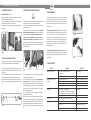
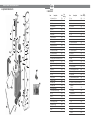
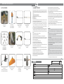
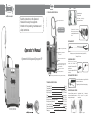
Tighten
Release
Read the instructions in this Operator's
Manual before using the equipment.
Attention to the operating, maintenance and
safety instructions.
illustrative Image
1. TECHNICAL SPECIFICATIONS
Adjustable buckles
Greater comfort
Fa c il i ta t es p os i t ion in g
equipment on the back.
Woven nylon reinforced hose
Figure 1
20 Litres - Code 405-11
16 Litres - Code 439-03
Symmetrical structure
allowing instant change of
operating sides without use of
tools.
Figure 2
DISCHARGE SET
New "L" lever, greater durability
Operator’s Manual
Filter with a greater filtration
surface area
Symmetrical Knapsack Sprayers SP
Dual mixer control, mechanical and
hydraulic
Connecting rod with pressure relief
valve for reducing wastage - as per
FAO specifications.
New snap-on connectors
Robust reinforced plastic base
New quick coupling and release harness buckle - greater ease and safety
Figure 3A
Complete spray nozzle, lance and control assembly set (Item 45).
Total length 744 mm
UNIVERSAL NOZZLE
Enables the use of any spray
nozzle, which follows the
standards of the international ISO
specifications.
Comes with adjustable GUARANY
conical tip.
DISCHARGE TYPE SUPER 3
Valve with fluoro-elastomer rings and filter built
into the hand-held control.
Trigger locking, allows for continuous spraying.
TECHNICAL SPECIFICATIONS
20 Litros cód./code: 405-11
16 Litros cód./code: 439-03
(5.3 gal.)
Tank capacity 20L
(4.2 gal.)
Tank capacity 16L
4.4 Kg (9.70 libras)
Weight empty 20L
4.3 Kg (9.47 libras)
Weight empty 16L
piston lever type
Pump
500 KPa (75 psi)
Maximum pressure
Working pressure (insecticide/fungicide)
300 KPa (45 psi)
Working pressure (herbicide)
100 KPa (15 psi)
Adj. nozzle flow 45psi
600 ml/min (0,15 gal./min)
poly-acetate
Pump cylinder material
copper
Pressure chamber Material
490 x 175 x 555 mm (19.3” x 6.9” x 21.8”)
Packaging
Figure 3B
Figure 3C
EFFICIENT VALVE SYSTEM
Pressure relief valve, prevents the
occurrence of excessive pressures
causing product wastage.
Lower part
Hemispherical valve (in elastomer)
efficient system for product
transference.
Upper part
Figure 4
19
OPERATOR’S MANUAL | Symetrical Knapsack Sprayers SP
2. ASSEMBLY INSTRUCTIONS
3. INSTRUCTIONS FOR CORRECT AND SAFE USE
4. SPRAY MAINTENANCE
PUMPING ROD ASSEMBLY (Figure 5)
1 - Remove the metal pumping rod (A) from the equipment box and remove the 2
clips and 1 washer that come attached to the rod;
2 - Fit the extremity of the rod with the smallest angle into orifice (B) of the lever
and insert washer and clip to keep the rod secured in place;
3 - Fit the other end of the rod into the head (C) of the pressure cylinder and insert
the securing clip.
C
WARNING
This equipment should only be utilized with agricultural chemicals approved by the
regulatory authorities in your country for use with knapsack sprayers.
For the possibility of using the equipment in the application of other substances,
consult the manufacturer.
Guarany does not recommend the use of chemical products based on flammable
solvents and highly concentrated fertilizers, such as ammonium nitrate and
sulfate (ammonium salts) and lime sulphur syrup in high concentrations.
During the handling and application of agrochemicals the use of
Personal Protective Equipment (PPE) is mandatory. Read the label and
package instructions of the chemical to determine what PPE (Personal Protection
Equipment) should be used and any other forms of protection needed during the
handling of these products.
A
B
2.1 SPRAY LANCE ASSEMBLY (FIGURE 6)
B
Remove the set - spray nozzle and lance - from the packing, which is located inside
the equipment tank and assemble according to the steps outlined below:
Figure 6
20
� Double bushing lubrication (Figure 8): For lubrication of the dual bushing
(item 16) you should first remove the clip and then remove the upper part of the
lever pump rod (Figure 5 C), unscrew the pump-securing cap (item 7) and
withdraw the mixer (item 29) fixed into the pressure cylinder (item 20) inside the
chemical tank (for this you must use PPE (Personal Protection Equipment) and
proper gloves to avoid contamination). Remove the pressure cylinder (item 25)
and coat the inner wall with grease or Vaseline to allow lubrication of the dual
bushing when in operation.
� Lubrication of Super 3 discharge valve (Figure 9): Disengage the items (G)
and (F) (Figure 6) and through one of the apertures add 3 drops of two-stroke
engine oil into item (F) (Figure 6) allowing the lubrication of the entire needle valve
assembly (item 44)
Figure 5
1º - Insert the filter tip (A) inside the body of the elbow joint (B) and then screw
together the coupling nut holding the adjustable conical nozzle (C) into the body of
the elbow joint;
2º - Insert the body of elbow joint (B) into the end of the spray lance, which comes
with a rubber bush and attach by tightening up the threaded connector (D);
3º - Attach the other end of the spray lance, with an orange colored bush (E), into
the super 3 valve outlet (F) and attach by tightening up the threaded connector
(G);
� Never leave the remains of agrochemicals in the spray tank; wash your sprayer
with clean water at the end of every workday, fill the tank to about 25% of its
volume with water and then spray for about 1 minute, into the an appropriate
container, allowing for thorough cleaning of the equipment. Follow this with the
lubrication procedure:
1º - After assembling the equipment, fill the tank with the prepared agrochemical
by passing the liquid through the filter (Item 2);
2º - The harness straps for this sprayer come with a new coupling and quick
release system (Figure 7A), which allows you to secure the strap with the
equipment already placed on the back (Figure 7B), providing greater agility at
work and the release of same just by turning the buckle in the direction indicated
by the arrow in (Figure 7C). This provides greater safety when it is necessary to
remove the knapsack sprayer quickly;
3º - Place the equipment on the back, by adjusting the straps through the
adjustable harness buckles (Figure 1);
4º - Move the pump lever until the desired working pressure is reached; the
equipment has a pressure relief valve (Figure 4) that will be activated when the
pressure in the tank exceeds 500 KPA (75 PSI). Note that when activated it may
make a slight noise, indicating the correct working pressure has been reached.
5º - To adjust the conical spray jet, simply turn the adjustable nozzle tip (Figure
3B).
Figure 9
5. TROUBLE SHOOTING
TROUBLE
Figure 7
Figure 8
THE CAUSE
SOLUTION
Lack of pressure in the pump
Dirt in the lower valve (item 14) or wear of
this component.
Dual bushing (item 16)
Cleaning/Replacing
Leakage of liquid from top of the
equipment
Filling above the maximum level
Tank lid (item 3) ‐ damaged/loose
Pump‐securing cap (item 7)/gasket (item 6) ‐ Damaged/loose
Cap valve (item 4)
Fill only up to the maximum level indicated
Change/Tighten
Change/Tighten
Tighten
Lever arm stiff
Change/Adjust
Suction tube (item 26) ‐ damaged/Loose
Note: Before mounting the suction tube, remove the product
from the inside of the tank and pressure cylinder holder (item 24).
Change/Clean
Lower Valve (item 14) ‐ Damaged/Dirty.
Lever arm loose
lower valves (item 14) and dual bushing (item 16).
Change
Dripping from adjustment point
Lance seal (item 43) ‐ Damaged
Air in the line
Change
Spray upwards for a few seconds
Discharge needle valve assembly (item 44) ‐ jammed
Change/Grease
Change
OPERATOR’S MANUAL | Symetrical Knapsack Sprayers SP
6. EQUIPAMENT SPARE PARTS
7. SPARE PARTS
27
28
*18
26
31
24
32
23
34
*14
21
22
29
25
36
17
*16
19
33
38
20
3
*4
*18
12
15
*14
7
42
2
05
02 Tank filter
7563
01
03 Tank lid with valve
8112
01
38 S3 valve control
6118
05
04 Cap valve
5613
06
39 S3 supply valve
9429
02
05 Harness clips
6457
10
40 Spring
6452
02
06 Plastic gasket
1649
04
41 O-ring
1455
10
07 Pump-Securing cap
1089
02
42 O-ring
2739
10
9320
06
08 Frame
10608
01
43 Lance seal
44 Complete needle valve assembly
8114
01
04
45 Complete spray/nozzle/lance assembly
4386
01
37
39
40
11 "L" lever with hand grip
10702
01
46 Lance tube w/threaded coupling
10704
01
12 Complete harness assembly
10703
01
47 Fully adjustable tip assembly
8118
01
13 Cylinder valve assembly
4647
01
48 Spray tip filter
1143
10
5066
10
49 Adjustable spray nozzle
4525
06
15 Complete cylinder and valve assembly set 8110
01
50 End nut
3441
04
16 Dual bushing
3707
10
51 Deflector tip
5374
06
17 Threaded sleeve coupling
3656
10
52 Service Kit*
10697
01
18 Clip
3000
06
53 Lance w/spray assembly
8115
01
20
54 Quick release/coupling harness buckles
10609
02
5007
01
55 Lever arm locking device
2812
10
21 O-ring
6715
01
56 Lance/elbow bush
6203
10
22 Pump Lever rod
10658
01
57 Lance/elbow threaded coupling and bush
4609
04
23 Rod locking clamp
6349
06
58 Elbow joint
10700
01
24 Pressure cylinder
4671
01
59 Complete elbow joint and spray nozzle assembly 10701
01
19 Flat washer
51 *
57
56
48
20 Plastic cylinder
46
59
58
47
9
10
2804
04
54
11
2805
37 Valve lever retainer
5949
52
55
36 Split pin
Code
5852
*41
53
8
01
Description
10 Hexagonal screw M8x40
1
50
6316
7569
Item
09 Frame securing nut
45
10
35 O-ring
Chemical tank 16 Litres
Code
*35
43
5
6
7564
Pcs/
Packing
06
Description
14 Lower valve
44
13
01 Chemical tank 20 Litres
Pcs/
Packing
01
Item
30
49
1038
25 Pressure cylinder
4756
01
* Sevice kit
26 Suction tube assembly
4423
01
Deflector tip
5374
27 Suction tube connector and O-ring
8119
01
Valve Diaphragm
5613
28 O-ring
6216
10
Hemispherical valve
5066
29 Mixer
2998
05
Dual bushing
3707
30 Hose 8x1300mm
4427
01
Clip
3000
02
O-ring
6316
1455
31 Hose coupling and washer
4428
32 Discharge valve grip
4426
01
O-ring
33 Discharge valve S3
4320
01
Spray tip filter
1143
34 Filter
6270
10
Relief valve
6711
Seal valve
6117
OPERATOR’S MANUAL | Symetrical Knapsack Sprayers SP
09. WARRANTY CERTIFICATE
8. LIST OF ACCESSORIES
Horizontal Rear Boom
U9888.00.00
Universal Boom
200 mm: K9798.00.00
400 mm: K9895.00.00
500 mm: K9960.00.00
Vertical Rear Boom
4 Nozzles: U9898.00.00
6 Nozzles: U4288.00.00
Liquid Metering Device
U4575.00.00
Universal S3 Discharge Set
(with Hose Connection)
U9537.00.00
Rotary Nozzle Discharge Set
U4750.00.00
Telescopic Discharge Lance
with Valve (1 Nozzle)
U9767.00.00
2 Nozzle Discharge Set
U4222.00.00
Guarany together with its accredited resale network and subject to the limits set by this Certificate
provides for the initial purchaser and user of this product, a warranty against any defects caused in the
manufacturing process. The Guarany technical assistance warranty covers the entire line of its
products.
GENERAL CONDITIONS OF WARRANTY:
1 - Guarany provides the purchaser the following guarantees:
Equipment Line: 1 year.
Consumer Line: 90 days.
Further to the conditions established in item 5, any claim invoking this warranty must be accompanied
by the original invoice to prove the purchase date of the product.
2 - For the full application of this warranty the buyer must return the product to an authorized Guarany
retail outlet (dealer). All costs and risks for shipping the product back to our dealer and its subsequent
return are the responsibility of the buyer. No claim for compensation or reimbursement of
transportation expenses will be accepted by Guarany or their agents. Any such repair is considered to
be an "over the counter" repair, i.e., the equipment is repaired by the dealer.
3 - Our dealers are authorized to replace the defective parts with original parts or Guarany alternatives,
while maintaining and respecting the equivalent integrity of the equipment's quality and performance.
Any equipment parts removed during the repairs performed under warranty become the property of
Guarany.
4 - The following items are not covered by this warranty:
4.A - Incorrect assembly, installation or use.
4.B - Components that can wear out naturally through regular use of the equipment such as:
O-rings, membranes, gaskets, valves, pistons, rings, bushings, drive-belts, hoses, pressure gauges,
bearings, spark plug, parts supplied in the kit that came with the product as well as components in
permanent contact with agrochemicals.
5 - The warranty will be automatically cancelled if or when:
5.A - The equipment is improperly installed, assembled or used;
5.B - The equipment contains any non-original parts or components;
5.C - The equipment was not used in accordance with the procedures described in our technical
bulletin and instruction manual provided with all our products;
5.D - There has occurred any mistreatment such as: damage; impact; dropping; bumping or if there
are holes found in the tank;
5.E - The equipment has been connected to a power supply with a voltage other than that specified on
the equipment and/or in the instruction manual (110 or 220V);
5.F - Whenever the oil/fuel mix indicated in our manual is not respected.
5.G - Repairs have been made by any person or entity not authorized by Guarany;
5.H - There has been any violation of the internal or external original features;
5.I - Used by non-qualified persons;
5.J - There has been negligence in the corrective or preventive maintenance;
5.K - The equipment has undergone changes that affect its function, stability or safety;
5.L - Erasures or tampering of the serial number or invoice have occurred.
6 - This warranty is limited to the repair or replacement of defective parts; no other expressed or
implied warranty is given to the buyer;
7 - Guarany is not responsible for any damage, loss, inconvenience, direct or indirect losses that may
arise from misuse of its products, or from the use of harsh or inappropriate chemicals or products not
compatible with the components in our equipment (any questions, doubts or concerns regarding
these items must be referred to an authorized dealer or retailer or directly through our telephone
customer service number +55 11 2118-8400)
8 - Claims for missing parts and accessories will be accepted only at the time of purchase and in the
presence of a representative from a Guarany authorized retailer/dealer.
9 - Guarany will continue to provide spare parts for our products for a period of up to five (5) years
from the date on which the factory discontinues the product.
10 - Guarany reserves the right to make technical changes to improve the product without prior
notice.
IMPORTANT:
* To keep your product original and with the same operational quality, use only our authorized network
(see our site www.guaranyind.com.br) ensuring the use of original replacement parts and skilled
labour.
* For any questions about the use of our equipment and products please consult our local distributor
or use our customer service e-mail [email protected].
* For possible claims covered by this Warranty Certificate, the invoice should be retained during the
warranty validity period.
* By purchasing this product, the purchaser agrees that Guarany may review, modify, enhance,
discontinue or change the equipment, parts or components at any time, as well as maintaining the
expressed conditions in this certificate without incurring any liability or obligation relative to the client;
* Our responsibility is limited to the terms of this warranty. The warranty is not transferrable and
ceases automatically in case of equipment resale.
HOW TO USE THE WARRANTY:
To qualify for these guarantee terms, the customer must make a claim at one of our technical
assistance points which are duly registered in the "national network" index; if the region does not have
a service point, the claim must be made at the store or distributor where the equipment was
purchased.
The defects should be thoroughly described in the defect claim form which can be obtained from our
technical assistance points or sales offices. The completed claim form should be delivered to the
technical assistance point together with the product requiring servicing and a copy of the original
invoice.
* Consult our product line in the website www.guaranyind.com.br
Dosimeter Valve
With applicator pipe: U8018.00.00
Without applicator pipe: U8096.00.00
Weed Control Shield
U7860.00.00
Discharge Tube
0,9m: K4281.00.00
1,2m: K4280.00.00
Flowrate Regulator with Pressure Gauge
U9634.00.00