1
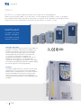
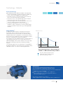
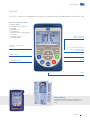
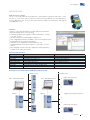
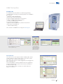
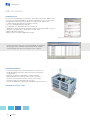
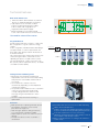
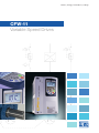
Motors | Energy | Automation | Coatings
CFW-11
Variable Speed Drives
www.weg.net
CFW-11
The CFW-11is a variable speed drive series with state of the art technology for
three-phase induction motors. It can be used in a wide range of applications, since it is designed
for running on either Normal or Heavy Duty loads. Its performance is excellent, providing increased
productivity and an improvement in the quality of the process in which it is used.
1.1 to 2.2kW - 1.5 to 3HP
200-240V - Single-phase
1.1 to 55kW - 1.5 to 75HP
200-240V - Three-phase
1.5 to 132kW - 2 to 175HP
380-480V - Three-phase
Innovative and simple
The CFW-11 presents many innovations that are helpful and
beneficial to customers, mainly due to the simplicity of its
installation and operation. The CFW-11 was developed
based on Plug-and-Play philosophy (connect and use)
allowing simple and fast installation of the VSD and its
accessories. The Keypad has a navigation and
programming system similar to mobile phones, with softkey buttons. It is possible to access the parameters
sequentially or through groups of parameters. The Keypad
also makes the Oriented Start-up function available, guiding
the user through the necessary programming.
Flexibility
The CFW-11 adapts itself to the customer’s needs through
a broad range of accessories, which are easily installed.
Besides this, the standard product comes with the SoftPLC
function that attributes PLC functions to the VSD, which
allows the customer to create his/her own applications
(user programs) through the WLP software (programming in
LADDER).
2
CFW-11
www.weg.net
Technology - Patents
Vectrue Technology ®
WEG VARIABLE SPEED DRIVE CONTROL TECHNOLOGY
g Linear and adjustable V/f, VVW (Voltage Vector WEG) and
vector controls are available in the same product.
g Two types of vector control: Sensorless and closed loop
Vector contro (Encoder Interface required).
g Sensorless vector control permits high torque and quick
response in open loop, even at low speeds.
g The self-tunning function automatically matches the vector
control or VVW to the motor and load used.
g Through the adjustable V/f control, it is possible, for
example, to adjust a quadratic V/f curve, providing energy
savings for quadratic torque loads (e.g.: centrifuge pumps
and fans).
Optimal Braking®
In applications where inertia is a relevant point and short
deceleration times is required, great amount of energy is
returned from the motor to the VSD. To handle this energy,
traditional VSDs have to dissipate it as heat in power resistors.
Such resistors are usually heavy and some instalation criterias
must be considered due to their heat dissipation.
As an option to the use of braking resistors, CFW-11 features a
special braking method in vector control mode known as “
Optimal Braking®. This innovation delivers to the load a high
performance braking torque without requiring a braking
resistor.
The following graph shows the advantages of using Optimal
Braking® compared to other methods, thus ensuring an ideal,
optimized and low cost solution for braking applications.
Braking Torque (%)
100 (%)
TB1
0
0
20%
100%
200%
Typical Braking Torque x Speed Graph for
a 10 HP / 7.5 kW motor driven by a CFW-11
Dynamic Braking Torque Curve
Optimal Braking® Torque Curve
DC Braking Torque Curve
Optimal Flux ®
TECHNOLOGY FOR MOTORS DRIVEN BY VSDs IN
APPLICATIONS WITH CONSTANT TORQUE LOADS
g Rated torque at low speeds eliminating the need for independent
ventilation or motor oversizing.
g Space saving and cost reduction of the application.
g Improved performance of the package VSD and motor
(an exclusive WEG solution).
High efficiency WEG motor + CFW-11
Solution applied only to CFW-11 with high efficiency WEG motors.
CFW-11
3
www.weg.net
Applications
The CFW-11 can be used in both simple and sophisticated applications, due
to its broad range of functions and easy configuration, installation and
operation. The CFW-11, through its Vectrue Inverter technology, presents
excellent static and dynamic performance, precise torque and speed control,
dynamic response, positioning precision, and high overload capacity. The
CFW-11 was also developed for applications where the decisive factor is
safety, through several built-in protections and alarms as well as through the
safety stop function in accordance with EN 954-1, category III.
Multi-Pump Control
The CFW-11 features the Multipump Control, which permits the CFW-11 to control up
to 5 pumps in order to maintain the pipeline pressure constant regardless of the
outflow fluctuations.
In this system, an intelligent control of the pumps is done by the VSD, which decides
the moment to start or stop each of the pumps based on the outflow demand.
Besides that, the VSD also monitors the suction pressure and the tank level.
The CFW-11 also alternates the pumps according to their using time, thus ensuring
an uniform wear and tear of motors and pumps.
Two types of Multipump Control are available: fixed and floating controls. In fixed
control, the VSD is able to control one of the pumps at variable speed and to start
and stop other 4 pumps at fixed speed. In floating control, the VSD is able to control
up to 4 pumps, all of them at variable speed.
The Multipump Control for CFW-11 is available as an applicative software for SoftPLC
function (see page 17) and can be downloaded from www.weg.net
Pumps and fans
g Precise control of process variables (pressure, flow, temperature, etc.) through a PID regulator superposed to the speed control.
g Optimization of power consumption through speed control with an adjustable V/f curve.
g Possibility of safety and maintenance signaling and alarms of pumps and fans.
g Availability of PID regulators to control other process accessories like valves, dumpers, other VSDs, etc.
Compressors
g Optimization of system pressurization control with energy savings and improvement of compressor efficiency.
g Reduction of motor startup current minimizing the wear and tear of the mechanical system permitting a reduction of contracted demand.
g Possibility of safety and maintenance signaling and alarms of pressurization system.
g Provides startup system control of other compressor units with an increased efficiency of the pressurization system.
4
CFW-11
www.weg.net
Applications
Paper and Cellulose / Wood
g Three monitoring parameters displayed at once on the HIM
g USB communication port at the front of the VSD for data monitoring and parameters configuration via software Superdrive.
g Highly precise speed and torque control.
g Flexible hardware programming and confguration, making easier applications where syncronism is demanded.
g Possibility to be integratet in a variety of communication protocols mainly
used in the industry.
g Provided in a compact design the CFW11 Series allows the assembly
directly next to one another with no reduction of ambient temperature.
g Quick and simplified programming.
g Highly reliable and robust.
g For large power ratings modular topology can be used( CFW-11M).
Cement and Mining
g Robust and large overload capacity(models sized in HD).
g Provided in a compact design the CFW11 Series allows the assembly directly next to one another with no reduction of ambient temperature.
g Possibility to be integrated in a variety of communication protocols mainly
used in the industry.
g Quick and simplified programming.
g Highly reliable and robust.
g For large power ratings modular topology is used( CFW-11M)
Chemical and Petrochemical
Highly reliable and robust.
g Provided in a compact design the CFW11 Series allows the assembly directly next to one another with no reduction of ambient temperature.
g Plug-and-play system for additional modules, ensuring elevated flexibility in adapting to existing systems.
g Possibility to be integrated in a variety of communication protocols mainly used in the industry.
g
Ironworks and Metallurgy
Highly precise speed and torque control.
g Large overload capacity (models sized in HD).
g Flexible hardware programming and configuration.
g Possibility to be integrated in a variety of communication protocols mainly used in the industry.
g Provided in a compact design the CFW11 Series allows the assembly directly next to one another with no reduction of ambient temperature.
g For large power ratings modular topology is used( CFW-11M)
g
CFW-11
5
www.weg.net
Applications
OverHead Crane / Lifting
g SoftPLC function.
g Three modes of vector control.
g Highly compact.
g Intelligent control of ventilation system.
Cooling
SoftPLC function built in the standard product enabling the use of two controllers simultaneously. This
characteristic is for HVAC applications.
g Three monitoring parameters displayed at once on the HIM
g USB communication port at the front of the VSD for data monitoring and parameters configuration via software Superdrive.
g
Sugar and Alcohol
Modular and compact.
g 12-pulse rectifier for reduction of harmonic content.
g Regenerative rectifier for centrifuges.
g Highly robust and reliable.
g
Process Machines
Built-in PLC and Real Time Clock.
g High connectivity.
g Fieldbus.
g Highly precise speed and torque in all speed ranges.
g User friendly interface and programming.
g
6
CFW-11
www.weg.net
Keypad
The CFW-11 keypad was developed for simple and fast interaction while providing excellent visibility for the user.
Easy to use Interface Tools:
g
g
g
g
g
g
g
g
Graphic display.
Soft-keys for easy operation.
Backlight.
Real time clock.
Copy function.
Plug-in (connection with CFW-11
turned on).
Language selection.
Remote Keypad.
Right soft-key: function
defined by the display
Left soft-key: function defined by
the display
Key for scrolling through menus and
parameters and for modifying
parameter content
FWD/REV Selection
Start key
Local / Remote Selection
Stop key
JOG key
Remote Keypad
The Keypad can be installed on panel doors or
machine consoles with a protection degree of
IP56.
CFW-11
7
www.weg.net
Monitoring Modes
The keypad can be configured to display reading parameters in three different modes.
Status Indication
g Run.
g Ready.
g Configuration.
g Self-tuning
g VSD disabled by fault and the
fault number.
g Last alarm.
Motor speed
BAR GRAPHS
LARGE CHARACTERS
NUMERIC VALUES
Time indication
FWD/REV Indication
Local / Remote Indication
Soft-key function
The keypad displays parameters in a hierarchy mode organized by groups.
Oriented Start-up
For simlpified Start-up, CFW-11 guides the user through the
necessary programming to adjust the VSD to the motor and
power supply.
Basic Application
The Basic Application Group contains the basic parameters,
which need to be adjusted in most applications. The CFW-11
guides the user through these parameters.
Fault History Group
It shows the parameters with the last 10 faults and the day,
month, year and time when they occured.
Read Only Parameters Group
It shows reading parameters only.
Backup Parameters Group
The Backup Parameters Group allows CFW-11 parameters
to be transferred to the Keypad or FLASH Memory Module
(available in the standard product) and vice versa. During
CFW-11 operation, the modified parameters are saved in the
FLASH Memory Module regardless of user command.
Functions Group
There are several groups divided by functions, only making
available only the parameters related to the function.
Example: Vector Control Group, Communication Group, I/O
Configuration Group, etc.
Selectable Language
The user can choose the Keypad language: Portuguese,
English, Spanish, German, etc.
Changed Parameters Group
It shows only the parameters that are programmed different
from the factory default.
8
CFW-11
www.weg.net
Accessories
CFW-11 was developed based on Plug-and-Play philosophy. It automatically recognizes and
manual configuration.
Slot 1 – I/O Expansion
(inputs and outputs)
Slot 2 – Encoder Interface
Slot 5 – Built-in flash Memory
Module (available in the
standard product)
Slot 3 – Communication 1
Slot 4 – Communication 2
CFW-11
9
www.weg.net
Accessories
Description
Name
2 14-bit analog inputs in voltage or current
2 digital inputs
2 14-bit analog outputs in voltage or current
2 open collector digital outputs
1
IOB-01
2 isolated 12-bit analog inputs
2 digital inputs
2 isolated 11-bit analog outputs in voltage or current
2 open collector digital outputs
1
ENC-01
Incremental encoder module
5 to 12 Vdc
100 kHz
With encoder signal repeater
ENC-02
Incremental encoder module
5 to 12 Vdc
100 kHz
RS485-01
RS-485 Serial Communication Module (Modbus-RTU)
RS232-01
RS-232C Serial Communication Module (Modbus-RTU)
RS232-02
RS-232C Serial Communication Module with DIP-switches for
microcontroller’s flash memory programming.
3
CAN/RS485-01
CAN/RS-485 Interface Module (CANopen, DeviceNet and Modbus)
3
CAN-01
CAN Interface Module (CANopen and DeviceNet)
RS232-05
RS-232 Interface Module (passive) (Modbus-RTU)
4
RS485-05
RS-485 Interface Module (passive) (Modbus-RTU)
4
PROFDP-05
Profibus DP Interface Module
DEVICENET-05
DeviceNet Interface Module
4
ETHERNET/IP-05
EtherNet/IP Interface Module
4
PLC11-01
Module with PLC Functions (see page 14)
PLC11-02
Module with PLC Functions (see page 14)
PLC Functions
Communication
Interface with Encoder
I/O Expansion
IOA-01
10
Slot
CFW-11
2
2
3
3
4
1, 2 and 3
Appearance
www.weg.net
Accessories
Kit for power cable shielding
CFW-11 has a kit to make easier the connection of the motor cable shield to the ground, providing a low-impedance
connection for high frequencies.
Name
Description
PCSA-01
Kit for power cable shielding for frame size A
PCSB-01
Kit for power cable shielding for frame size B
PCSC-01
Kit for power cable shielding for frame size C
PCSD-01
Kit for power cable shielding for frame size D
PCSE-01
Kit for power cable shielding for frame size E
Note: 1) The kit for power cable shielding is provided PCSD-01, PCSE-01 along
with VSDs that have internal RFI filter.
Example: EU CFW11 0007 T 2 O FA Z
2) In frame sizes D and E the power cable shielding kit is factory standard,
even for VSDs without internal RFI filter.
Enclosures
Standards
Ratings
IP20
IEC
NEmA
Frame Sizes
A
B
C
D
E
-
-
-
X
X
IP21
X
X
X
KIP21D-01
-
TYPE 1
KN1A-01
KN1B-01
KN1C-01
X
KN1E-01 / KN1E-02
( X ) Standard
( - ) NA
Name
Description
KN1A-01
Conduit kit for frame size A
KN1B-01
Conduit kit for frame size B
KN1C-01
Conduit kit for frame size C
KIP21D-01
Conduit kit for frame size D
NEmA type 1 kit for frame size E models CFW110142T2,
CFW110105T4 and CFW110142T4
NEmA type 1 kit for frame size E models CFW110180T4 and CFW110211T4
KN1E-01
KN1E-02
Note: in the KN1X-01 Conduit kit ( Frames size A,B and C) power cable shielding is also provided
Safety stop in accordance with EN-954-1, category III1
With the activation of the safety stop function, the PWM pulses of the
IGBTs are disabled. Since no voltage is available in the VSD output, no
torque is applied to tje motor. Thus, it is ensured that the motor remains
stopped providing system safety (pending certification).
CFW-11
11
www.weg.net
Accessories
Blank cover – HMID - 011
Blank cover to replace the standard VSD keypad when not used.
Remote keypad frame – RHMIF-01
Frame for Keypad installation on panel door or machine console.
Degree of protection IP56.
External control supply in 24 Vdc¹
Used with communication networks (Profibus DP, DeviceNet,
EtherNet/IP, etc.) so that the control circuit and the interface for
the communication network continue working even if the AC
supply is removed.
RFI suppressor filter1 (for the VSD to be in accordance
with EN 61800-3 and EN 55011)
CFW-11 models with built-in RFI filter, when properly installed,
meet the requirements of the electromagnetic compatibility
directive – “EMC Directive 2004/108/EC”.
Example: EU CFW11 0007 T 2 O FA Z
For models from frame size A to D, the RFI filter is optional. But
for models in frame size E, the RFI filter is included in the
standard product.
1
These options must be provided already installed in the CFW-11 (please see coding on page 26).
12
CFW-11
www.weg.net
Accessories
PLC Accessory - PLC11
PLC11 accessory provides the CFW-11with PLC , speed reference generator and motion control
functions. It comes in two options: PLC11-01 and PLC11-02 (see differences in the table below).
In many applications, this accessory allows the CFW-11 to replace an external PLC, reducing this
way application costs.
Features:
g Motion control with trapezoidal “S” profiles (absolute and relative)
g Machine initial position search (homing)
g Ladder programming through WLP Software with timers, counters,
coils and contacts
g RS-485 serial interface with Modbus-RTU protocol
g 100 configurable parameters available to the user via keypad or WLP
g Master/Slave function (Electronic Gearbox)
g CAN interface for CANopen and DeviceNet protocols
g CANopen Master, which allows CFW-11 to control up to 25 slave
devices
g WLP/ WSCAN software: network configuration and programming
software in the same environment.
Technical Specification
Input and Outputs
Digital inputs
Digital outputs
Relay outputs
Enconder inputs
RS-485 serial interface
CAN interface
Analog inputs
Analog outputs
PLC11-01
9 bidirectional isolated inputs: 24Vdc
3 bidirectional isolated open-collector outputs: 24Vdc, 500mA
3 outputs NO contacts: 250Vac, 3A
2 incremental enconder inputs: 5...12Vdc, 500mA, internal
1 port for modbus-RTU protocol
1 port for CANopen and DeviceNet protocols
1 differential input: -10...+10Vdc / 0...20mA, 14 bits
2 outputs: -10...+10Vdc/ 0...20mA, 12 bits
PLC11-02
4 bidirectional isolated inputs: 24Vdc
3 bidirectional isolated open-collector outputs: 24Vdc, 500mA
1 output NO contact: 250Vac, 3A
2 incremental encoder inputs: 5...12Vdc, 500mA, internal
1 port for modbus-RTU protocol
1 port for CANopen and Devicenet ptotocols
Example of use of PLC11-01 as CANopen network master
CANopen slave
WLP / WSCAN Software
CANopen slave
WLP / WSCAN Software
8
Digital and analog I/Os
7
6
Master
Master
5
Digital and analog I/O expansion
4
3
Digital and analog I/Os
2
1
CFW-11
13
www.weg.net
CFW-11 IP-54 Drive
The CFW11 IP-54 features a IP-54 enclosure that protects the drive from splashing
water, corrosion and dust.
Due to the fact that the CFW11 IP-54 Drive has improved cooling fans it ensures
perfect functionality when operating at full load condition.
The Drive is designed to be mounted directly in severe environments without need
of custom enclosure, such as:
g Chemical industry
g Petrochemical
g Food Industry
Comunication Protocol such as Profibus, Devicenet, CAN open, Modbus-RTU,
Ethernet IP can be added using optional cards.
CFW-11 Multipump Control Function
The CFW-11 features the Multipump Control function which is capable of controlling up to 5 pumps in order to maintain the
pipeline pressure constant regardless of the outflow fluctuations.
In this system, an control algoritm of pumps is done by the VSD, which decides
the moment to start or stop each of the pumps based on the outflow demand. Besides that, the VSD also monitors the suction
pressure and the tank level.
The CFW-11 also alternates the pumps according to their using time, thus ensuring an uniform wear and tear of motors and
pumps.
Two types of Multipump Control are available: fixed and floating controls. In fixed control, the VSD is able to control one of the
pumps at variable speed and to start and stop other 4 pumps at fixed speed. In floating control, the VSD is able to control up
to 4 pumps, all of them at variable speed.
14
CFW-11
www.weg.net
USB Connection
SuperDrive G2
It is a Windows-based software for CFW-11 programming,
command and monitoring. The following features are available in
the software:
g Automatic CFW-11 identification
g Monitoring of CFW-11 parameters
g Online changing of parameters in the CFW-11
g Offline changing of parameters in the PC
g Creation of application documents
g Trace function (see below)
g Upload of SoftPLC applicative software in the CFW-11
flash memory (see page 17)
g
Online troubleshooting
This software is available free of charge at www.weg.net
Monitoring and parameterization of
the list of parameters. Comparison
to factory default is easy.
Integrated environment
Monitoring and
command window
using virtual Keypad.
Start/Stop function,
JOG, local / remote,
Reverse and reset
Trace Function
Trace function is used to register CFW-11 variables (like current,
voltage, speed, etc.) when a given event occurs in the system
(eg.: alarm / fault, overload, overvoltage, etc.).
This event in the system is called a trigger because it triggers the
data storage process.
The stored variables can be visualized in the form of graphs by
using the SuperDrive G2 software. Trace function simulates a
4-channel oscilloscope.
It is a very useful tool in the start-up of a system and in the
diagnoses of defects.
Parameter setting
Status monitoring
Example of graph visualization screen
Trace function configuration in the SuperDrive G2
CFW-11
15
www.weg.net
USB Connection
SoftPLC Function
It is a resource that provides PLC features to the CFW-11 without the addition of any
accessories. It provides flexibility to the product, allowing the user to create his/her
own applicative software (user’s program). The SoftPLC main features are:
g Ladder language programming using WLP software
g Access to all VSD parameters and I/Os
g Configurable PLC, mathematical and control blocks
g Applicative software download, upload and online monitoring via USB connection
g
Storage of the applicative software in the CFW-11 Flash
g Memory Module (see below)
g Memory space of 15kB for applicative storage
Simple and practical programming environment
g
40 User parameter settings that can be individually programmed
allowing tags, units, minimum and maximum values, number
of decimal digits and other characteristics to be changed.
Flash Memory Module
g It stores the image of the CFW-11 parameters. It ensures that
the programming will not be lost because there is a backup of
the parameters.
g It permits the transfer of parameters stored in the flash
Memory Module to the CFW-11 and vice versa. Excellent
function for machine manufactures or in processes where
parameter settings is repeated (Copy Function).
g It stores the applicative software generated by the SoftPLC function.
Standard on CFW11 series
16
CFW-11
www.weg.net
Technical Features
Built-in DC link Reactor
g
Allows the VSD to be installed in any network
(there is no minimum impedance restriction).
g Typical power factor for rated condition:
0.94 for models with three-phase supply
0.70 for models with single-phase or
single-phase/three-phase supply
g Meets the 61000-3-12 standard, related
to low order current harmonics in the network.
No need for external line reactor
Single DC Busbar
Usually used in multi-motor systems, common DC
bus confguration is a good solution for energy
savings.
In this confguration, individual VSD rectifer bridges
are replaced with a common input rectifer unit.
Each VSD is then directly fed from the DC bus to
its DC link terminals.
This solution allows the energy in the DC bus to be
shared among the VSDs connected to it, thus
optimizing the power consuption in the system.
The standard CFW-11 can be conected to a DC
bus system. ( When required the factory should be
consulted for further details)
Supply Network
Single DC Link
General Input
Rectifier Unit
CFW-11
1
2
3
4
n
Intelligent Thermal Management
Monitoring of the heatsink and internal air
temperatures of the electronic boards providing
total protection of the IGBTs and the CFW-11
as a whole.
g The heatsink fan is turned on and off
automatically, depending on the temperature
of the power modules.
g The speed and the number of hours of operation
of the fan are monitored and indicated in
corresponding parameters. Alarm or fault
messages are generated related to these
variables.
g The fan is easily removed for cleaning or
replacement.
g
Functions
Multi-speed: up to 8 pre-programmed speeds.
g PID regulator: automatic control of level,
pressure, flow, weight, etc.
g Ride-Through: operation during momentary
Loss of the power of thepower supply.
g Skip Frequency: rejection of critical or resonant
speeds.
g S Ramp: smoothness in the acceleration /
deceleration.
g
g
g
g
g
All CFW models from size A to D have built-in braking
IGBT in the standard product.
CFW-11 can monitor the temperature probes of the mo
tor (PTC, PT100 OR KTY84), providing thermal protection
to the motor (optional accessory is necessary).
Operating air temperature up to 50}C (122}F) for sizes A
to D, and up to 45}C (113}F) for size E.
Motor overload protection according to IEC 60497-4-2
and UL 508}C
CFW-11
17
www.weg.net
Technical Features
(Slot 4 Anybus)
18
CFW-11
www.weg.net
Drive Ratings
Normal Duty (ND) Cycle:
g 110% during 60 seconds every 10 minutes
g 150% during 3 seconds every 10 minutes
Heavy Duty (HD) Cycle:
g 150% during 60 seconds every 10 minutes
g 200% during 3 seconds every 10 minutes
Sizing the drive:
The correct way to select a VSD is matching its output current with the motor rated current. However, the tables below present
the expected motor power for each VSD model.
Use the motor power ratings below only as a guidance. Motor rated currents may vary with speed and manufacturer.
IEC motor powers are based on WEG 4-pole motors, NEMA motor powers are based on NEC table 430-150.
Motor voltages between 220V and 230V:
IEC
50Hz
220V
230V
kW
1.1
1.5
2.2
1.1
1.5
1.5
2.2
3
4
5.5
7.5
9.2
11
15
18.5
22
30
37
55
55
Normal Duty
(ND)
Power
Supply
Model
CFW110006S2
CFW110007S2
CFW110010S2
CFW110006B2
CFW110007B2
CFW110007T2
CFW110010T2
CFW110013T2
CFW110016T2
CFW110024T2
CFW110028T2
CFW110033T2
CFW110045T2
CFW110054T2
CFW110070T2
CFW110086T2
CFW110105T2
CFW110142T2
CFW110180T2
CFW110211T2
1Ø
1/3Ø
200-240 V
3Ø
220-230V
3Ø
A
6
7
10
6
7
7
10
13
16
24
28
33.5
45
54
70
86
105
142
180
211
NEMA
IEC
50Hz
220V
230V
kW
1.1
1.5
2.2
1.1
1.5
1.1
1.5
2.2
3
5.5
5.5
7.5
9.2
11
15
18.5
22
30
37
55
Heavy Duty
(HD)
60Hz
230V
HP
1.5
2
3
1.5
2
2
3
3
5
7.5
10
10
15
20
25
30
40
50
60
75
A
5
7
10
5
7
5.5
8
11
13
20
24
28
36
45
56
70
86
115
142
180
NEMA
60Hz
230V
HP
1
2
3
1
2
1
2
3
3
5
7.5
10
10
15
20
25
30
40
50
60
Motor voltages between 380V and 460V:
IEC
Power
Supply
380-480 V
Model
3Ø
CFW110003T4
CFW110005T4
CFW110007T4
CFW110010T4
CFW110013T4
CFW110017T4
CFW110024T4
CFW110031T4
CFW110038T4
CFW110045T4
CFW110058T4
CFW110070T4
CFW110088T4
CFW110105T4
CFW110142T4
CFW110180T4
CFW110211T4
IEC
NEMA
Normal Duty
(ND)
50Hz
380V
415V
60Hz
440V
460V
60Hz
460V
A
3.6
5
7
10
13.5
17
24
31
38
45
58.5
70.5
88
105
142
180
211
kW
1.5
2.2
3
4
5.5
7.5
11
15
18.5
22
30
37
45
55
75
90
110
HP
2
3
4
7.5
10
12.5
15
20
30
30
40
50
75
75
100
150
175
HP
2
3
3
5
7.5
10
15
20
25
30
40
50
60
75
100
150
150
NEMA
Heavy Duty
(HD)
50Hz
380V
415V
60Hz
440V
460V
60Hz
460V
A
3.6
5
5.5
10
11
13.5
19
25
33
38
47
61
73
88
115
142
180
kW
1.5
2.2
2.2
4
4
5.5
9.2
11
15
18.5
22
30
37
45
55
75
90
HP
2
3
3
7.5
7.5
10
12.5
15
25
30
30
50
60
75
75
100
150
HP
2
3
3
5
7.5
7.5
10
15
20
25
30
40
50
60
75
100
150
CFW-11
19
www.weg.net
Dimensions and Weight
model
Size
CFW110006S2
CFW110006B2
CFW110007S2
CFW110007B2
CFW110007T2
CFW110010S2
CFW110010T2
CFW110013T2
CFW110016T2
CFW110024T2
CFW110028T2
CFW110033T2
CFW110045T2
CFW110054T2
CFW110070T2
CFW110086T2
CFW110105T2
CFW110142T2
CFW110180T2
CFW110211T2
CFW110003T4
CFW110005T4
CFW110007T4
CFW110010T4
CFW110013T4
CFW110017T4
CFW110024T4
CFW110031T4
CFW110038T4
CFW110045T4
CFW110058T4
CFW110070T4
CFW110088T4
CFW110105T4
CFW110142T4
CFW110180T4
CFW110211T4
A
NEmA 1 / IP21
IP54
Dimensions
mm (in)
Dimensions
mm (in)
High (H)
Width (W)
Depth (D)
247
(9.73)
145
(5.71)
227
(8.94)
Weight
kg (lb)
Size
High (H)
6.3
(13.9)
1
Width (W)
410
(16.14)
255
(10.04)
Depth (D)
235
(9.25)
Weight
kg (lb)
Braking IGBT
10
(22.0)
Standard
B
293
(11.54)
190
(7.48)
227
(8.94)
10.4
(22.9)
C
378
(14.88)
220
(8.67)
293
(11.54)
20.5
(45.2)
D
504
(19.84)
300
(11.81)
305
(12.01)
32.6
(71.8)
E
675
(26.58)
335
(13.19)
358
(14.09)
65
(143.3)
A
247
(9.73)
143
(5.63)
196
(7.72)
6.3
(13.9)
293
(11.54)
190
(7.48)
227
(8.94)
10.4
(22.9)
C
378
(14.88)
220
(8.67)
293
(11.54)
20.5
(45.2)
D
504
(19.84)
300
(11.81)
305
(12.01)
32.6
(71.8)
E
675
(26.58)
335
(13.19)
358
(14.09)
65
(143.3)
625
(24.61)
350
(13.78)
298
(11.73)
-
-
-
-
1
410
(16.14)
255
(10.04)
235
(9.25)
2
36
(79.4)
41
(90.4)
-
10
(22.0)
15
(33.1)
2
625
(24.61)
350
(13.78)
298
(11.73)
-
-
-
-
Optional
Standard
36
(79.4)
41
(90.4)
-
Optional
H
H
B
15
(33.1)
W
D
D
W
Frame Size B
H
H
H
Frame Size A
D
W
W
Frame Size C
20
CFW-11
Frame Size D
D
Frame Size E
W
D
www.weg.net
Mechanical Mounting
Standard Installation
30mm
(1.18 in)
30mm
(1.18 in)
A
Frame Size
Minimum Mounting Clearance
A mm (in)
B mm (in)
C mm (in)
A
25 (0.98)
25 (0.98)
10 (0.39)
B
40 (1.57)
45 (1.57)
10 (0.39)
C
110 (4.33)
130 (5.12)
10 (0.39)
D
110 (4.33)
130 (5.12)
10 (0.39)
E
According to the model (see user’s manual)
B
When one VSD is assembled on the top of another, use the distance A+B
and deflect the hot air coming from the VSD below.
C
Side by side Installation
Only for Frame Size A, B and C: side by side assembly without
lateral spacing and with the removal of the top cover.
Space Saving
CFW-11
21
www.weg.net
Mechanical Installation | Panel Assembly
Surface Assembly
Frame Size
a2 mm (in)
b2 mm (in)
A
115 (4.53)
250 (9.85)
c2 mm (in)
m5
B
150 (5.91)
300 (11.82)
m5
C
150 (5.91)
375 (14.77)
m6
D
200 (7.88)
525 (20.67)
m8
E
200 (7.88)
650 (25.60)
m8
Airflow
Flange Assembly (IP-54 rated when mounting the heat-sink outside the enclosure)
Frame Size
a3 mm (in)
b3 mm (in)
c3 mm (in)
d3 mm (in)
A
130 (5.12)
240 (9.45)
m5
135 (5.32)
225 (8.86)
B
175 (6.84)
285 (11.23)
m5
179 (7.05)
271 (10.65)
C
195 (7.68)
365 (14.38)
m6
205 (8.08)
345 (13.59)
D
275 (10.83)
517 (20.36)
m8
285 (11.23)
485 (19.10)
E
275 (10.83)
635 (25.00)
m8
315 (12.40)
615 (24.21)
Airflow
22
e3 mm (in)
CFW-11
www.weg.net
Technical Data
Performance
Power supply and Power Range
200-240Vac / +10% - 15%
1.5 to HP (1.1 to 2.2 kW)
200-240Vac / + 10% -15%:
1.5 to 75HP (1.1 to 30 kW)
380-480Vac / + 10% -15%:
2 to 175HP (1.5 to 45kW)
Sigle Phase
Voltage and
power range
Three Phases
Frequency
50...60Hz +/-2% (48 to 63Hz)
Displacement factor
Greater than 0.98
Efficiency
Greater than 0.97
Power factor
0.94 for three-phase input at rated condition
0.70 for single-pahse input at rated condition
Regulation: 1% of rated speed
V/f
Speed variation range: 1:20
Regulation: 1% of rated speed
Voltage Vector
(VVW)
Speed variation range: 1:30
Regulation: 0.5% of rated speed
Sensorless Vector
Speed
Control
Speed variation range: 1:100
Regulation: +/- 0.01% of rated speed
with 14-bit analog input (IOA)
Inverter Output
Voltage range
Three Phase, 0 up to power supply voltage
Frequency range
0 to 3.4x motor rated frequency (*)
Switching Frequency
Standard: 5kHz (frame sizes A, B, C, D);
Options available 2.5 / 5 / 10kHz (most of frame size E models)
Vector with
Encoder
(with accessory
ENC-01 or ENC-02)
Range: 10 to 180%
150% for 3 sec every 10min
Overload
Regulation: +/- 5% of rated torque
150% for 1 min every 10min
Heavy Duty Cycle
Torque
Control
200% for 3 sec every 10min
Acceleration
0 to 999 seconds
Deceleration
0 to 999 seconds
Sensorless Vector
Environment
Range: 20 to 180%
Regulation: +/-10% of rated
torque (above 3 Hz)
Inputs and Outputs (I/Os) in the Standard Product
-10 to 50°C (14 to 122°F) for frame S Size A,B,C and D
-10 to 45°C (14 to 113°F) for frame S Size E models
Temperature of
Operation
Regulation: +/- 0.05% of rated speed
with 12-bit analog input
110% for 1 min every 10min
Normal Duty Cycle
Time (ramps)
Regulation: +/- 0.01% of rated speed with
digital reference (keyboard, serial
fieldbus, electronic potentiometer,
multispeed)
Digital
Up to 60°C (140°F) for frame Size A,B,C,D and 55°C (133°F)
for frame Size E with current derating (2% for each 1°C
above rated value or 1.1% for each 1°F above rated value)
6 isolated inputs, 24 Vdc, programmable functions
2 differential inputs isolated by differential
amplifier, programmable functions
rated value or 1.1% for each 1°F above rated value
Resolution:
- AI1: 12 bits
- AI2: 11 bits + signal
Humidity
5 to 90% without condensation
Altitude
Up to 4000 meters with current reduction
(1% for every 100 meters above 1000 meters)
Signals: 0 to 10Vdc, 0 to 20mA or 4 to 20mA
Protection Degree
Impedance:
- 400 kΩ for signal 0 to 10Vdc
- 500 Ω for signal 0 to 20mA or 4 to 20mA
0 to 1000 meters
IP20
Frame Size A, B and C without upper cover and conduit kit and
frame size E without conduit kit
Nema 1 / IP20
Frame Size D without IP21 kit
Frame size E with conduit kit
IP21
Frame Size A, B and C with upper cover and conduit kit
Nema 1 / IP21
Frame Size A, B and C with upper cover and conduit kit
Inputs
Relay
3 relays with NO / NC contacts, 240 Vac / 1A, programmable functions
2 isolated outputs, programmable functions
Outputs
Frame Size D with IP21 kit
Resolution: 11 bits
Analog
Load:
0 to 10 V: R L >= 10 kΩ
0 to 20 mA or 4 to 20 mA: R L < 500Ω
Braking Methods
Rheostatic Braking
Analog
Supply available to user (standard for frame size A, B, C and
D and option for frame size E)
External braking resistor (not provided)
Optimal Braking
Does not need braking resistor
DC Braking
Direct current applied to the motor
Available
supply
to user
24 Vdc + -20%, 500 mA
(*) This maximum value can change according to the used control mode and switching frequency. The maximum permissible speed is 18000rpm.
CFW-11
23
www.weg.net
Technical Data
Communication
Profibus DP
DeviceNet
PROFIBUS DP-05 (slot 4)
Overcurrent / short circuit
CAN/RS485-01 (slot 3)
Under / overvoltage in the power circuit
CAN-01 (slot 3)
Phase loss
DEVICENET-05 (slot4)
Overtemperature in the VSD
(IGBTs, rectifier and internal air
in the electronic cards)
CAN/RS485-01 (slot 3)
CANopen
Protections
CAN-01 (slot 3)
Overtemperature in the motor
CANopen Master/Slave
PLC11-01 1, 2 and 3
Ethernet TCP/IP
ETHERNET/IP-05 (slot 4)
Overload in the braking resistor
RS485-01 (slot 3)
ModBus RTU
(RS-485)
CAN/RS485-01 (slot 3)
RS485-05 (slot 4)
RS232-01 (slot 3)
ModBus RTU
(RS-232)
Overload in the IGBTs
Overload in the motor
Fault / external alarm
Fault in the CPU or memory
RS232-05 (slot 4)
Phase-to-ground short circuit at the output
Built-in the standard product
Fault in the heatsink fan
Communication with SuperDrive G2 Software
USB
Communication with WLP Software used for
programming and monitoring the SoftPLC
function and the PLC11 accessories
Safety Standards
UL 508C
Power conversion equipment
UL 840
Insulation coordination including clearances and creepage distances
for electrical equipment
EN 61800-5-1
Safety requirements electrical, thermal and energy
Overspeed of motor
Incorrect connection of encoder
Electromagne Compatibility Standards (EMC)
EN 61800-3 - Adjustable speed electrical power drive systems
Part 3: EMC product standard including specific test methods
EN 55011 - Limits and methods of measurement of radio disturbance
characteristics of industrial, scientific and medical (ISM)
radio-frequency equipment
EN 50178
Electronic equipment for
use in power installations
CISPR 11 - Industrial, scientific and medical (ISM)radio-frequency
equipment Electromagnetic disturbance characteristics Limits and methods
of measurement
EN 60204-1
Safety of machinery.
Electrical equipment of machines.
Part 1: General requirements.
Note: In order to have a machine in conformity with this norm, the
machine manufacturer is responsible for the installation of an
emergency shutdown device and an equipment for network sectioning
EN 61000-4-2 - Electromagnetic Compatibility Standards (EMC)
Part 4: Testing and measurement techniques Section 2: Electrostatic discharge immunity test
EN 61000-4-3 - Electromagnetic Compatibility Standards (EMC)
Part 4: Testing and measurement techniques Section 3:Radiated, radiofrequency, electromagnetic field immunity test
EN 60146 (IEC 146) Semiconductor converters
EN 61800-2
Adjustable speed electrical power drive systems – Part 2: General
requirements – rating specifications for low voltage adjustable
frequency a.c. power drive systems
EN 61000-4-4 - Electromagnetic Compatibility Standards (EMC)
Part 4: Testing and measurement techniques Section 4: Electrical fast transient / burst immunity test
EN 61000-4-5 - Electromagnetic Compatibility Standards (EMC)
Part 4: Testing and measurement techniques Section 5: Surge immunity test
Mechanical Construction Standards
EN 60529 - Degrees of protection provided by enclosures (IP Code)
UL 50 - Enclosures for electrical equipment
24
CFW-11
EN 61000-4-6 - Electromagnetic Compatibility Standards (EMC)
Part 4: Testing and measurement techniques Section 6: Immunity to conducted disturbances,
induced by radio-frequency fields
www.weg.net
Coding
1
EU
2
3
CFW11
0016
4
T
5
4
6
S
7
_
8
_
9
_
10
_
11
_
12
_
13
_
14
_
15
Z
1 - Market identification
It defines the language of the manual and the factory parameterization
BR = Brazil
NA = North America
MS = Mercosul
EU = Europe
SA = South Africa
2 - Line
CFW11 = WEG Frequency VSD series CFW11
3- Rated output current for normal overload system
Supply
Single-phase (S)
Single-phase or Three-phase (B)
200 - 240 V (2)
200 - 240 V (2)
200-240 V (2)
380-480 V (4)
0010 = 10 A
0006 = 6 A
0007 = 7 A
0010 = 10 A
0013 = 13 A
0016 = 16 A
0024 = 24 A
0028 = 28 A
0033 = 33 A
0045 = 45 A
0054 = 54 A
0070 = 70 A
0086 = 86 A
0105 = 105 A
0142 = 142A
0180 = 180A
0211 = 211A
0003 = 3 A
0005 = 5 A
0007 = 7 A
0010 = 10 A
0013 = 13 A
0017 = 17 A
0024 = 24 A
0031 = 31 A
0038 = 38 A
0045 = 45 A
0058 = 58 A
0070 = 70 A
0088 = 88 A
0105 = 105 A
0142 = 142A
0180 = 180A
0211 = 211A
0007 = 7 A
Voltage
Three-Phase (T)
4 – Number of phases
S = Single-phase
B = Single-phase or three-phase
T = Three-phase
10 - RFI Filter
Blank = factory standard
FA = Category C3 internal RFI filter
(Valid for models of frame (size E: built-in RFI filter) Size A, B, C and D)
5 - Voltage
2 = 200-240 V
4 = 380-480 V
11 - Safety Stop
Blank = factory standard (without safety stop function)
Y = with safety stop function according to EN-954-1 category 3
6 - Optional Accessories
S = standard product
O = product with optional accessories
12 - External Electronic Supply 24 Vdc
Blank = factory standard
W= With external eletronic power supply 24Vdc
( Sizes A,B,C,D,E: Without external eletronic power supply 24vdc in the
standard product)
7 - Degree of Protection
Blank = factory standard
(Sizes A, B and C: IP21 - D: Nema 1/ IP20)
N1 = Nema 1
21 = IP21
13 – Special hardware
Blank = factory standard (without)
H1 = special hardware nr. 1
8 - Keypad
Blank = factory standard (1)
IC = without interface (blind cover)
14 – Special Software
Blank = factory standard (without)
S1 = special software nr. 1
9 - Braking
Blank = factory standard
(Sizes A, B, C , D: built-in braking IGBT)
DB = with braking IGBT (valid for models of frame size E)
15 – End of Code indicator digit
Z = end of code indicator
CFW-11
25
www.weg.net
CFW11M - Modular Drive
The CFW-11M (modular drive) is the new generation of WEG VSDs for large powers. It is available at
power ratings from 400 to 2500 HP and voltages from 500 to 690 V, with 6 and 12 pulse input
rectifier.
Notes: The fuses presented in the block diagram above are not included in the
VSD CFW-11M, but are part of the AFW-11M drive
Maximum AFW-11M configuration with 5 power units (2500 HP)
DC Link (connected to rectifier)
Power Units
Compact modular VSD units that can be
configured to the applicable motor power.
g Easy servicing.
g Configurable up to 5 power units.
g DC supplied by an input rectifier.
g Compact book format (width much smaller than
the depth).
Configurable up to 5 power book units
Power Book Unit
26
CFW-11
Output to motor
www.weg.net
CFW11M - Drive Ratings
Sizing the Drive
The correct way to select a VSD is matching its output current with the motor rated current. However, the tables below present
the expected motor power for each VSD model.
Use the motor power ratings below only as a guidance. Motor rated currents may vary with speed and manufacturer. IEC
motor powers are based on WEG 4-pole motors; NEMA motor powers are based on NEC table 430-150.
Motor Voltages between 380-480V
IEC
Normal Duty
(ND)
Power
Supply
Model
3Ø
380-480 V
CFW11M 0600T4
50Hz
380V
415V
NEMA
60Hz
380V
460V
60Hz
460V
IEC
Heavy Duty
(HD)
50Hz
380V
415V
NEMA
60Hz
380V
460V
60Hz
460V
A
kW
HP
HP
A
kW
HP
HP
600
315
450
500
515
280
350
450
CFW11M 1140T4
1140
630
850
1000
979
500
700
800
CFW11M 1710T4
1710
900
1250
1500
1468
800
1100
1250
CFW11M 2280T4
2280
1250
1750
2000
1957
1120
1350
1750
CFW11M 2850T4
2850
1600
2000
2500
2446
1250
1750
2000
Motor Voltages between 500-600V
IEC
Normal Duty
(ND)
3Ø
500-600 V
Power
Supply
Model
50Hz
525V 575V
NEMA
60Hz
575V
60Hz
575V
IEC
Heavy Duty
(HD)
50Hz
525V 575V
NEMA
60Hz
575V
60Hz
575V
A
kW
HP
HP
A
kW
HP
HP
CFW11M 0470T5
470
355
500
500
380
280
400
400
CFW11M 0893T5
893
630
1000
1000
722
500
800
800
CFW11M 1340T5
1340
1000
1350
1500
1083
800
1250
1100
CFW11M 1786T5
1786
1250
1750
1750
1444
1120
1500
1350
CFW11M 2232T5
2232
1600
2500
2500
1805
1400
2000
2000
Motor Voltages between 660-690V
IEC
3Ø
660-690 V
Power
Supply
Model
IEC
Normal Duty
(ND)
50Hz
660V 690V
60Hz
660V
Heavy Duty
(HD)
50Hz
660V 690V
60Hz
660V
A
kW
HP
A
kW
HP
CFW11M 0427T6
427
400
550
340
315
400
CFW11M 0811T6
811
710
1000
646
560
800
CFW11M 1217T6
1217
1120
1500
969
900
1250
CFW11M 1622T6
1622
1600
2000
1292
1250
1750
CFW11M 2028T6
2028
2000
2500
1615
1400
2000
CFW-11
27
WEG Worldwide Operations
AUSTRALIA
WEG AUSTRALIA PTY. LTD.
3 Dalmore Drive
Carribean Park Industrial Estate
Scoresby VIC 3179 - Melbourne
Phone(s): 61 (3) 9765 4600
Fax: 61 (3) 9753 2088
[email protected]
www.weg.net/au
BELGIUM
WEG BENELUX S.A.
Rue de l’Industrie 30 D,
1400 Nivelles
Phone(s): + 32 (67) 88-8420
Fax: + 32 (67) 84-1748
[email protected]
www.weg.net/be
CHILE
WEG CHILE S.A.
Los Canteros 8600
La Reina - Santiago
Phone(s): (56-2) 784 8900
Fax: (56-2) 784 8950
[email protected]
www.weg.net/cl
CHINA
WEG (NANTONG) ELECTRIC
MOTOR MANUFACTURING CO.,
LTD.
No. 128# - Xinkai South Road,
Nantong Economic &
Technical Development Zone,
Nantong, Jiangsu Province.
Phone(s): (86) 0513-85989333
Fax: (86) 0513-85922161
[email protected]
www.weg.net/cn
COLOMBIA
WEG COLOMBIA LTDA
Calle 46A N82 - 54
Portería II - Bodega 7 - San
Cayetano II - Bogotá
Phone(s): (57 1) 416 0166
Fax: (57 1) 416 2077
[email protected]
www.weg.net/co
FRANCE
WEG FRANCE SAS
ZI de Chenes – Le Loup
13 Rue du Morellon – BP 738
38297 Saint Quentin Fallavier
Phone(s): +33 (0) 4 74 99 11 35
Fax: +33 (0) 4 74 99 11 44
[email protected]
www.weg.net/fr
GERMANY
WEG GERMANY GmbH
Industriegebiet Turnich 3
Geigerstrasse 7
D-50169 Kerpen-Turnich
Phone(s): +49 (0) 2237 9291-0
Fax: +49 (0) 2237 9291-10
[email protected]
www.weg.net/de
INDIA
WEG Electric (India) Pvt. Ltd.
#38, Ground Floor, 1st Main
Road, Lower Palace Orchards,
Bangalore – 560 003
Phone(s): +91-80-4128 2007
+91-80-4128 2006
Fax: +91-80-2336 7624
[email protected]
www.weg.net/in
ITALY
WEG ITALIA S.R.L.
V.le Brianza 20 - 20092 - Cinisello
Balsamo - Milano
Phone(s): (39) 02 6129-3535
Fax: (39) 02 6601-3738
[email protected]
www.weg.net/it
JAPAN
WEG ELECTRIC MOTORS
JAPAN CO., LTD.
Matsumoto Bldg. 2F, 3-23-7
Kamata, Ohta-ku,
Tokyo, Japan 144-0052
Phone(s): (81) 3 3736-2998
Fax: (81) 3 3736-2995
[email protected]
www.weg.net/jp
MEXICO
WEG MEXICO, S.A. DE C.V.
Carretera Jorobas-Tula Km. 3.5,
Manzana 5, Lote 1
Fraccionamiento Parque
Industrial - Huehuetoca,
Estado de México - C.P. 54680
Phone(s): + 52 (55) 5321 4275
Fax: + 52 (55) 5321 4262
[email protected]
www.weg.net/mx
WEG Equipamentos Elétricos S.A.
International Division
Av. Prefeito Waldemar Grubba, 3000
89256-900 - Jaraguá do Sul - SC - Brazil
Phone:55 (47) 3276-4002
Fax: 55 (47) 3276-4060
www.weg.net
NETHERLANDS
WEG NETHERLANDS
Sales Office of
WEG Benelux S.A.
Hanzepoort 23C
7575 DB Oldenzaal
Phone(s): +31 (0) 541-571080
Fax: +31 (0) 541-571090
[email protected]
www.weg.net/nl
PORTUGAL
WEG EURO - INDÚSTRIA
ELÉCTRICA, S.A.
Rua Eng. Frederico Ulrich
Apartado 6074
4476-908 - Maia
Phone(s): +351 229 477 705
Fax: +351 229 477 792
[email protected]
www.weg.net/pt
RUSSIA
WEG RUSSIA
Pochainskaya Str. 17
Nizhny Novgorod
603001 - Russia
Phone(s): +7-831-2780425
Fax: +7-831-2780424
[email protected]
www.weg.net/ru
SPAIN
WEG IBERIA S.L.
Avenida de la Industria,25
28823 Coslada - Madrid
Phone(s) : (34) 916 553 008
Fax : (34) 916 553 058
[email protected]
www.weg.net/es
SINGAPORE
WEG SINGAPORE PTE LTD
159, Kampong Ampat,
#06-02A KA PLACE.
Singapore 368328.
Phone(s): +65 6858 9081
Fax: +65 6858 1081
[email protected]
www.weg.net/sg
SWEDEN
WEG SCANDINAVIA AB
Box 10196
Verkstadgatan 9
434 22 Kungsbacka
Phone(s): (46) 300 73400
Fax: (46) 300 70264
[email protected]
www.weg.net/se
UK
WEG ELECTRIC
MOTORS (U.K.) LTD.
28/29 Walkers Road
Manorside Industrial Estate
North Moons Moat - Redditch
Worcestershire B98 9HE
Phone(s): 44 (0)1527 596-748
Fax: 44 (0)1527 591-133
[email protected]
www.weg.net/uk
UNITED ARAB EMIRATES
WEG MIDDLE EAST FZE
JAFZA – JEBEL ALI FREE ZONE
Tower 18, 19th Floor,
Office LB181905
Dubai – United Arab Emirates
[email protected]
www.weg.net/ae
USA
WEG ELECTRIC CORP.
1327 Northbrook Parkway,
Suite 490
Suwanee 30024
Phone(s): 1-770-338-5656
Fax: 1-770-338-1632
[email protected]
www.weg.net/us
VENEZUELA
WEG INDUSTRIAS VENEZUELA C.A.
Avenida 138-A
Edificio Torre Banco Occidental de
Descuento, Piso 6 Oficina 6-12
Urbanizacion San Jose de Tarbes
Zona Postal 2001
Valencia, Edo. Carabobo
Phone(s): (58) 241 8210582
(58) 241 8210799
(58) 241 8211457
Fax: (58) 241 8210966
[email protected]
www.weg.net/ve
1053.04/112009 - The values shown are subject to change without prior notice.
ARGENTINA
WEG EQUIPAMIENTOS
ELECTRICOS S.A.
(Headquarters San
Francisco-Cordoba)
Sgo. Pampiglione 4849
Parque Industrial San Francisco
2400 - San Francisco
Phone(s): +54 (3564) 421484
Fax: +54 (3564) 421459
[email protected]
www.weg.net/ar