1
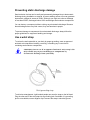
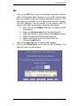
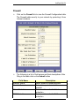
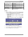
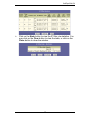
CellPipe®
22A-GX Series
User Guide
September 2004
Copyright © 2004 Lucent Technologies Inc. All rights reserved.
This material is protected by the copyright laws of the United States and other
countries. It may not be reproduced, distributed, or altered in any fashion by any entity
(either internal or external to Lucent Technologies), except in accordance with
applicable agreements, contracts, or licensing, without the express written consent of
Lucent Technologies. For permission to reproduce or distribute, please email your
request to [email protected].
Notice
Every effort was made to ensure that the information in this document was complete
and accurate at the time of printing, but information is subject to change.
Safety, Compliance, and Warranty Information
Before handling any Lucent Access Networks hardware product, read the Edge
Access Safety and Compliance Guide, which can be found at
http://www.lucentdocs.com/ins. See the warranty card included in your product
package for the limited warranty that Lucent Technologies provides for its products.
See Appendix C for further information on regulatory compliance.
Security Statement
In rare instances, unauthorized individuals make connections to the
telecommunications network through the use of access features.
Trademarks
Lucent, the Lucent logo, and all Lucent brand and product names are trademarks or
registered trademarks of Lucent Technologies Inc. Other brand and product names
are trademarks of their respective holders.
Ordering Information
You can order the most up-to-date product information and computer-based training
online at http://www.lucentdocs.com/ins.
How to comment
To comment on this information product, go to the Online Comment Form
(http://www.lucent-info.com/comments/enus/) or email your comments to the
Comments Hotline ([email protected]).
Customer Service
Lucent Technologies is the value added reseller (VAR) of certain CellPipe products.
To ensure you receive the latest and most up-to-date information in a timely manner,
Lucent is providing you with the latest original equipment manufacturer (OEM)
documentation. Thus, references to both Lucent and the OEM might appear in the
documentation. Lucent and its OEMs hope their combined efforts result in the best
documentation for the existing range of products.
Finding information and software
To obtain software upgrades and documentation for these products, log in to the
Lucent OnLine Customer Support at http://www.lucent.com/support.
Lucent OnLine Customer Support also provides technical information, product
information, and descriptions of available services. The center is open 24hours a day,
seven days a week. Log in and select a service.
Obtaining technical assistance
Lucent OnLine Customer Support at http://www.lucent.com/support also
provides easy access to technical support. You can obtain technical assistance
through email or the Internet, or by telephone. If you need assistance, make sure that
you have the following information available:
•
Active service or maintenance contract number, entitlement ID, or site ID
•
Product name, model, and serial number
•
Software version or release number
•
Software and hardware options. If supplied by your carrier, service profile
identifiers (SPIDs) associated with your line
•
Your local telephone company’s switch type and operating mode, such as
AT&T 5ESS Custom or Northern Telecom National ISDN-1
•
Whether you are routing or bridging with your Lucent product
•
Type of computer you are using
•
Description of the problem
Obtaining assistance through email or the Internet
If your services agreement allows, you can communicate directly with a technical
engineer through Email Technical Support or a Live Chat. Select one of these sites
when you log in to http://www.lucent.com/support.
Calling the technical assistance center (TAC)
If you cannot find an answer through the tools and information of Lucent OnLine
Customer Support or if you have a very urgent need, contact TAC. Access Lucent
OnLine Customer Support at http://www.lucent.com/support and click
Contact Us for a list of telephone numbers inside and outside the United States.
Alternatively, call 1-866-LUCENT8 (1-866-582-3688) from any location in North
America for a menu of Lucent services. Or call +1 510-747-2000 for an operator. You
must have an active services agreement or contract.
Preventing static discharge damage
Semiconductor devices can be easily and permanently damaged due to electrostatic
discharge during installation or removal. A person walking across a floor can generate
electrostatic voltages in excess of 5000V. Although you might not notice a discharge
of less than 3500V, discharges below 100V can damage semiconductor components.
You can destroy a component without noticing any electrostatic discharge. Because
these discharges have very little current, they are harmless to people.
To prevent damage to components from electrostatic discharge, always follow the
proper guidelines for equipment handling and storage.
Use a wrist strap
To reduce the static potential on your body by proper grounding, wear an approved
antistatic wrist strap when installing, removing, or handling any Lucent device
containing semiconductor components.
CAUTION: Correct use of an approved antistatic wrist strap is the
only reliable way to prevent damage to components by
electrostatic discharge from your body.
Wrist grounding strap
To minimize entanglement, right-handed people can wear the strap on the left hand.
Plug the other end of the wrist strap into a grounding jack if available. If a grounding
jack is not available, use an alligator clip to connect the strap to electrical ground.
Use the following two simple tests to verify that the wrist strap is functioning properly:
•
Measure the resistance between the wrist strap and its grounding plug.
Overall resistance between these two points must be approximately 1
megohm. If it is not, replace the strap.
•
Physically examine the strap for visible damage. If you see any damage,
replace the strap.
Remove plastics from your work area
Work areas must be kept clear of common plastics, such as the following items:
•
Polystyrene packing containers
•
Clear plastic bags
•
Plastic drinking cups
•
Food wrappers
•
Clear cellophane tape
These types of common plastic materials can carry a static charge that is not easily
discharged to ground and must not make direct contact with any solid state
components.
Store components properly
Protect components when not in use by storing them in their original factory packing
materials. Storage in approved antistatic packaging is acceptable when factory
packaging is unavailable.
CAUTION: Never place unprotected components directly on
ungrounded metal shelving or on ungrounded carts without
insulating surfaces.
Table of Contents
1
GETTING STARTED..................................................... 1
OVERVIEW ............................................................................. 1
FEATURES .............................................................................. 2
PACKAGING ............................................................................ 3
APPEARANCE ......................................................................... 4
HARDWARE INSTALLATION..................................................... 6
MANAGEMENT ....................................................................... 7
DEFAULT VALUES ................................................................... 8
SOFTWARE UPGRADE ............................................................. 9
CONSOLE SETUP................................................................... 10
2
WEB INTERFACE MANAGEMENT.........................11
OVERVIEW ........................................................................... 11
PREPARATION ....................................................................... 11
LOGIN .................................................................................. 12
HOME................................................................................. 13
LAN .................................................................................... 15
LAN Config ..................................................................... 15
DHCP Mode.................................................................... 16
DHCP Mode.................................................................... 17
DHCP Server .................................................................. 17
DHCP Relay.................................................................... 18
WAN.................................................................................... 19
DSL ................................................................................. 19
ATM VC........................................................................... 21
Point to Point Protocol (PPP) ........................................ 22
Ethernet over ATM (EoA) ............................................... 23
IP over ATM (IPoA) ........................................................ 25
BRIDGING............................................................................. 27
Bridging .......................................................................... 27
ROUTING .............................................................................. 28
IP Route........................................................................... 28
SERVICES ............................................................................. 30
NAT ................................................................................. 30
RIP .................................................................................. 34
Firewall ........................................................................... 35
IP Filter........................................................................... 36
Domain Name Service (DNS) ......................................... 40
Blocked Protocols ........................................................... 41
ADMIN ................................................................................. 42
User Config ..................................................................... 42
Commit & Reboot............................................................ 43
Local Image Upgrade ..................................................... 44
Remote Image Upgrade .................................................. 45
Alarm............................................................................... 46
Diagnostics ..................................................................... 47
Port Settings.................................................................... 48
3
QUICK PROTOCOL SETUP...................................... 49
OVERVIEW ........................................................................... 49
RFC 1483 BRIDGE ............................................................... 50
PPPOE ROUTE CONFIGURATION .......................................... 53
RFC 1483 + NAT ................................................................ 55
PPPOA ROUTE CONFIGURATION .......................................... 58
IPOA ROUTE CONFIGURATION ............................................. 62
DHCP CONFIGURATION ....................................................... 65
NAT CONFIGURATION .......................................................... 68
APPENDIX A – SPECIFICATIONS................................... 70
HARDWARE SPECIFICATIONS ................................................ 70
SOFTWARE SPECIFICATIONS ................................................. 71
APPENDIX B – REGULATIONS ....................................... 73
FCC PART 15 NOTICE .......................................................... 73
IC CS-03 NOTICE ................................................................ 74
UL NOTICE .......................................................................... 75
CellPipe 22A-GX
1 Getting Started
Overview
The CellPipe 22A-GX is multi-mode ADSL Router, compliant with
ANSI T1.413 Issue 2, ITU G.992.1 (G.dmt) Annex A, G.992.2 (G.lite).
CellPipe 22A-GX provides high-speed Internet access via one WAN
port over ATM over ADSL, and also connects to a corporate network
via one 10/100BaseTX Ethernet port and one USB port. CellPipe
22A-GX allows the service provider to deploy ADSL rapidly over
existing wire infrastructure (POTS or ISDN line).
1
CellPipe 22A-GX
Features
High speed asymmetrical data transmission on a single
twisted copper pair
Full rate operations up to 8Mbps downstream (12Mbps to
be provided) and up to 1Mbps upstream. G.lite operation
up to 1.5Mbps downstream and 512Kbps upstream
One 10/100BaseTx Ethernet port and one USB port for PC
connection
DHCP server
management
support
for
easy
LAN
IP
address
Supports PPPoE (RFC2516), PPP (RFC2364), and IP
(RFC 2225/RFC1577) over ATM over ADSL
RFC2684 (RFC1483) Bridged/Routed for both LLC/VC
MUX
Allows LAN users to access the Internet through Network
Address Translation (NAT, IP sharing) simultaneously
Local OAM&P through command line interface via RJ-45
Ethernet port or RS-232 Craft port (optional)
Configuration and management via Telnet and Web
browser through the Ethernet and ADSL interfaces
Supports applications such as TFTP, DHCP, Telnet, HTTP,
and FTP
Firmware upgradeable through TFTP
Interoperability complies with TR-48, U-R2
Supports dying gasp detection (optional)
-2-
CellPipe 22A-GX
Packaging
This package contains the following items:
CellPipe 22A-GX ADSL device
unit
RJ-45 Cable
RJ-11 Cable
AC Adapter
User’s Manual CD
-3-
CellPipe 22A-GX
Appearance
Front Panel
1 2
Label
1
2
3
4
LAN
USB
PWR
WAN
5
ALM
LED
Status
ON
ON
ON
Blinking
ON
Blinking
ON
3
Color
4 5
Description
Green
Green
Green
Green
Green
Red
Red
-4-
Ethernet port is connected.
USB port is connected.
Power supply is connected.
Training with DSLAM.
ADSL link is ready.
Booting up.
Error.
CellPipe 22A-GX
Rear Panel
1
1
2
3
4
Label
PWR
ETHERNET
USB
RESET
5
WAN
2
3 4 5
Description
Power jack; connect to a power adapter
RJ-45 port; connect to a PC or LAN
USB port; connect to a PC
Reset the modem back to factory settings by
holding down on this button
RJ-11 or RJ-45 port; connect to the ADSL
outlet.
-5-
CellPipe 22A-GX
Hardware Installation
The following section describes how to set up CellPipe 22A-GX with
a single computer.
As shown in the diagram below, both the USB and Ethernet ports
can be used at the same time. However it is recommended that
you use only one port during setup. Once you have verified that
you can access the Internet, you can then connect a second
computer.
Step 1:
Connect one end of the ADSL cable to the WAN port of
CellPipe 22A-GX and the other end to the ADSL wall outlet.
Step 2:
Use a RJ-45 cable to connect one end to the Ethernet port
of CellPipe 22A-GX, and the other end to the LAN or a PC
with an Ethernet adapter installed. You may also connect
a USB cable from the USB port to a PC.
Step 4:
Plug in the AC adapter to the AC power socket, and the
other end into the PWR inlet of CellPipe 22A-GX.
2
3
Power Supply
PC
1
ADSL Outlet
Note: Be sure to use a RJ-45 crossover cable while connecting to a hub.
-6-
CellPipe 22A-GX
Management
CellPipe 22A-GX supports simple, flexible, and easy-to-operate
methods for management purposes. CellPipe 22A-GX can be
managed via the following paths:
Local Ethernet Port (Telnet) – connect the Ethernet port
to your local area network or to directly to a PC. “Telnet”
CellPipe 22A-GX from any workstation in the LAN. The
default local Ethernet IP address is “192.168.1.1”.
Local Ethernet Port (Web Browser) – connect the
Ethernet port to your local area network or directly to a PC.
Launch your web browser and enter default local Ethernet
IP address “192.168.1.1” into the address bar.
ADSL Port from Remote Site – while the ADSL
connection is in service, you may remotely “Telnet”
CellPipe 22A-GX from a workstation connected to the CO
equipment.
Note: As operating an ADSL device requires technical know-how and
experience. It is recommended that only qualified technical staffs
manage CellPipe 22A-GX. Therefore, a password authentication is
required when you enter the web interface. To obtain the password, see
the Default Values section.
-7-
CellPipe 22A-GX
Default Values
CellPipe 22A-GX is pre-configured with the following parameters;
you may also re-load the default parameters by rebooting the router
into the Default configuration from the web browser.
Default Mode: Bridge
User Name: root
Password: root
Bridge Mode Setting
WAN and ADSL
Ethernet (local) IP: 192.168.1.1
Local Line Code: Auto
USB Interface (local) IP: 192.168.2.1
Subnet Mask: 255.255.255.0
Trellis Mode: Enable
Full Duplex: Auto
FDM Mode: Fdm
Protocol: RFC1483, Bridge Mode
Coding Gain: Auto
VPI/VCI: 8/35
Transmit Power Atten:
0dB
Class (QoS): UBR
Spanning Tree: Disable
Packet Filter: Any
DHCP Server: Disable
Router Mode Setting
Ethernet (local) IP: 192.168.1.1
DNS Relay: Disable
USB Interface (local) IP: 192.168.2.1
Subnet Mask: 255.255.255.0
Note: The User Name and Password are case-sensitive
-8-
CellPipe 22A-GX
Software Upgrade
You may easily upgrade CellPipe 22A-GX embedded software by
obtaining the compressed upgrade kit from the service provider then
following the steps:
Extract the ZIP file for updated firmware.
Connect CellPipe 22A-GX via the local ethernet port or
remote ADSL link. Make sure that the CellPipe 22A-GX IP
address and your terminal is properly configured, then you
can successfully “ping” CellPipe 22A-GX. The default local
IP address is 192.168.1.1.
Under DOS prompt, execute FTP command “open <IP
address of CellPipe 22A-GX>”, then input user name and
password.
Execute upload command “put teimage.bin“.
This upgrading process might last as long as 60 seconds.
Then reboot CellPipe 22A-GX with new software.
Note 1: CellPipe 22A-GX software may also be upgraded through the
web interface.
Note 2: Strictly maintain stable power to CellPipe 22A-GX while
upgrading its software. If the power fails during the upgrading process,
contents in the memory could be destroyed, and the system may hang.
In such a case, you must call the dealer or system integrator for repairs.
-9-
CellPipe 22A-GX
Console Setup
Connect the RS-232 console port to an ASCII data terminal or a PC
with Widows serial Terminal mode of VT-100 (Hyper Terminal). To
start the Hyper-terminal, follow the steps below.
1.
Start "Hyper-terminal" program
On Windows 98 or Windows NT
Click on the Start button
Programs
Accessories
Double Click “Hypertrm.exe”
Hyper Terminal Group
Enter Connection Name
Select Icon
Click on the
OK button.
2.
Select COM port to communicate with CellPipe 22A-GX.
Choose direct to COM1 or COM2 and click on the OK
button.
3.
Set Port Properties -Port Setting:
− Bit per second: 38400
− Data bits: 8
− Stop bits: 2
− Parity bits: None
− Flow Control: None
Settings:
− Function, arrow, and ctrl keys act as: Windows keys
− Emulation: Auto-detect
− Back-scroll buffer lines: 500
ASCII Setup:
− Echo typed characters locally
− Line delay: 0 milliseconds
− Character line feeds incoming line ends: enable
- 10 -
CellPipe 22A-GX
2 Web Interface Management
Overview
The Web management is provided in order to manage the ADSL
device as easily as possible. It provides a very user-friendly
configuration and graphical interface through a Web based platform.
You can configure a bridge or a router, as you feel appropriate. In the
section below, each configuration item is described in detail.
Preparation
1) Please refer the hardware installation procedure to install
modem.
2) You should configure the PC to the same IP subnet as the
modem.
For example: The modem: 192.168.1.1
Your PC: 192.168.1.x
3) Let your PC access the modem, and make sure that the
PING function is working properly. The default IP address
of this modem could be found in the default settings
section.
4) Open the Web browser (Internet explorer or Netscape),
enter the default IP address “192.168.1.1” for the website
address to access the web management page.
5) The Login dialog box will pop up first.
- 11 -
CellPipe 22A-GX
Login
The window Enter Network Password will pop up while
starting the configuration. With the window open, type admin for
both User Name and the Password. You can also edit the
Username and Password or add new users.
After you log into the web interface, you will notice that it is
divided into seven different sections, or tabs. From this point on,
each tab is described in detail along with instructions for
configuration. The seven tabs are:
•
•
•
•
•
•
•
Home
LAN
WAN
Bridging
Routing
Services
Admin
- 12 -
CellPipe 22A-GX
HOME
After logging in, the first tab that will be displayed is the Home
tab. Under this tab, the System View page is displayed. This
page displays a summary of the interfaces and their settings.
This page is divided into five sections. The table below
describes each section.
- 13 -
CellPipe 22A-GX
Section Name
Device
DSL
WAN Interface
LAN Interface
Services Summary
Description
Displays model name, hardware/software
version, device mode, uptime, current time,
time zone, daylight savings time, and domain
name.
Displays operation status, last state, DSL
version, and DSL standard.
Displays the WAN interface name,
encapsulation type, IP address, subnet mask,
lower interface, VPI/VCI values, and
operational status.
Displays the LAN interface name, MAC
address, IP address, subnet mask, lower
interface, transmission speed, duplex type
and operational status.
Displays the interface name, and
enabled/disabled features, such as: NAT, IP
filter, RIP, DHCP relay, DHCP client, DHCP
server, and IGMP.
To add, change, or remove any of the interface settings, click on
the interface name.
Click on the Modify button to set the device date, time, time
zone, and other related settings. Click on the Submit button
when completed.
- 14 -
CellPipe 22A-GX
LAN
Click on the LAN tab to view its sub-menu and configure the LAN
settings. The four sub-menu are: LAN Config, DHCP Mode, DHCP
Server, and DHCP Relay. Each sub-menu is described below.
LAN Config
Click on the LAN Config link to change the LAN IP address/
subnet mask, decide where the LAN is getting its IP address from,
and enable or disable IGMP. Follow the steps below in order to
configure the LAN settings.
1. Get LAN Address:
a. Select Manual if you would like to enter your own IP
address. Select External DHCP Server if a DHCP
server other than this device would assign the IP
addresses. Select Internal DHCP Server if you
would like this device to assign the IP addresses.
2. LAN IP Address: Enter the LAN IP address into these text
boxes.
3. LAN Network Mask: Enter the subnet mask of the LAN IP
address into these text boxes.
4. IGMP: Depending on your ISP’s settings, choose to enable
or disable IGMP.
5. USB IP Address:
6. USB Network Mask: Enter the same subnet mask of the
LAN IP address into the text boxes.
7. Click on the Submit button when completed.
- 15 -
CellPipe 22A-GX
- 16 -
CellPipe 22A-GX
DHCP Mode
Click on the DHCP Mode link to select a DHCP setting. From the
drop down list, select DHCP Server, DHCP Relay, or None. Click on
the Submit button when completed.
DHCP Server
Click on the DHCP Server link to view the DHCP Server settings.
The table displays the DHCP server settings, including start IP, end
IP, domain name, gateway address, and status. Click on the Add
button to enable a DHCP server and fill in the IP information based
on your ISP settings.
- 17 -
CellPipe 22A-GX
DHCP Relay
Click on the DHCP Relay link to view the DHCP Relay settings. Fill
in the DHCP server IP address in the text boxes and select an
interface name from the dorp down list. Click on the Add button to
complete the DHCP Relay configuration.
- 18 -
CellPipe 22A-GX
WAN
Click on the WAN tab to view its sub-menu and configure the WAN
settings. The five sub-menu are: DSL, ATM VC, PPP, EOA, and
IPOA. Each sub-menu is described below.
DSL
Click on the DSL link to view the DSL status. Click on the DSL
Param button to view the DSL parameters and the Stats button
to view the DSL statistics. Both the DSL Parameters and DSL
Statistics will be described below.
Click on the Clear button to clear and refresh the DSL status.
You may also change the page refresh rate by selecting a
different time period from the Refresh Rate drop down list.
- 19 -
CellPipe 22A-GX
DSL Parameters
Click on the
DSL Param
button to view
the
DSL
parameters.
Another
window
will
then display
the
DSL
parameters,
which may be
different from
the
one
shown below, due to the type and speed of the network. Click
on the Close button to close the window, or click on the
Refresh button to refresh the status.
DSL Stats
Click on the Stats
button to view the
DSL
status.
Another window
will then display
the DSL status,
which may be
different due to
the type and
speed of the
network.
Click
on the Close
button to close
the window, or
click
on
the
Refresh button
to refresh the
status.
- 20 -
CellPipe 22A-GX
ATM VC
Click on the ATM VC link to view the ATM VC table. This table
displays the interface name, VPI/VCI values, Mux type, and
maximum protocols per AAL5.
Click on the trash can icon to delete the current interface, or
edit the current interface by clicking on the pencil icon.
Click on the Add button to another interface.
After you click on the Add button, another window will pop-up.
First, select a VC interface from the drop down list. Then, enter
the VPI, VCI values into the text box. Select a Mux type from the
drop down list, and then enter the number of protocols per AAL5
in the text box.
Click on the Submit button when completed.
- 21 -
CellPipe 22A-GX
Point to Point Protocol (PPP)
Click on the PPP link to view the PPP configuration table. This
table displays PPP information such as: interface name,
interface type, protocol, WAN IP, gateway IP, default route,
DHCP, DNS, and operation status.
Click on the trash can icon to delete the current interface, or
edit the current interface by clicking on the pencil icon.
Click on the Add button to another interface.
After you click on the Add button, another window will pop-up.
- 22 -
CellPipe 22A-GX
The following is a list of field names and their descriptions. After
filling in the table, click on the Submit button when completed.
Field Name
Description
PPP Interface
Select an interface name from the drop down
list.
Select an ATM VC from the drop down list.
ATM VC
Interface Sec Type Select between public, private, or DMZ.
Select start, stop, or start on data.
Status
Select between PPPoA or PPPoE.
Protocol
Service Name
Enter a name for this service in the text box.
Use DHCP
Select between enable or disable.
Select between enable or disable.
Use DNS
Select between enable or disable.
Default Route
Security Protocol
Select between PAP or CHAP.
Enter the username for this service.
Login Name
Enter the password for this service.
Password
Ethernet over ATM (EoA)
Click on the EOA link to view the RFC1483/EoA configuration
table. This table displays EoA information such as: interface
name, interface security type, lower interface, config IP, network
IP, DHCP, default route, gateway IP, and status.
Click on the trash can icon to delete the current interface, or
edit the current interface by clicking on the pencil icon.
Click on the Add button to add another interface.
After you click on the Add button, another window will pop-up.
- 23 -
CellPipe 22A-GX
The following is a list of field names and their descriptions. After
filling in the table, click on the Submit button when completed.
Field Name
EoA Interface
Interface Sec Type
Lower Interface
Conf IP Address
Netmask
Use DHCP
Default Route
Gateway IP Address
Description
Select an interface name from the drop
down list.
Select between public, private, or DMZ.
Select a lower interface name from the drop
down list.
Enter the LAN IP address here.
Enter the subnet mask here.
Select between enable or disable.
Select between enable or disable.
Enter the gateway IP address here.
- 24 -
CellPipe 22A-GX
IP over ATM (IPoA)
Click on the IPoA link to view the IP over ATM configuration
table. This table displays IPoA information such as: interface
name, interface security type, lower interface, config IP, network
IP, subnet mask gateway IP, and status.
Click on the trash can icon to delete the current interface, or
edit the current interface by clicking on the pencil icon.
Click on the Add button to add another interface.
After you click on the
Add button, another
window will pop-up.
The following is a list of
field names and their
descriptions. After filling
in the table click on the
Submit button when
completed.
- 25 -
CellPipe 22A-GX
Field Name
IPoA Interface
Conf IP Address
Interface Sec Type
Netmask
RFC 1577
Use DHCP
Default Route
Gateway IP Address
Description
Select an interface name from the drop
down list.
Enter the LAN IP address here.
Select a lower interface name from the drop
down list.
Enter the subnet mask here.
Select between Yes or No to use RFC 1577.
Select between enable or disable.
Select between enable or disable.
Enter the gateway IP address here.
- 26 -
CellPipe 22A-GX
Bridging
Click on the Bridging tab to view its sub-menu and configure the
bridge settings. The six sub-menu are: Bridging, LAN Config, DSL,
ATM VC, and RFC 1483 Interface (EoA). The bridging sub-menu is
described below. (Each of the other sub-menus is described in the
earlier sections.)
Bridging
Click on the Bridging link to view the Bridge configuration. This
table displays bridge information, such as: interface name.
Click on the trash can icon to delete the current interface, or
edit the current interface by clicking on the pencil icon.
There are three radio buttons on this page. In order to use
bridging, you must enable Bridging and WAN to WAN
Bridging.
Click on the Submit button when completed.
- 27 -
CellPipe 22A-GX
Routing
Click on the Routing tab to view its sub-menu and configure the
routing settings. The eight sub-menu are: IP route, IP address, LAN
Config, DSL, ATM VC, PPP, EoA, and IPoA. The IP route
sub-menu is described below. (Each of the other sub-menus is
described in the earlier sections.)
IP Route
Click on the IP Route link to view the IP route table. This table
displays IP route information such as: destination, net mask,
next hop, interface name, route type and route origin. This table
lists IP addresses of Internet destinations commonly accessed
by your network. When a computer requests to send data to a
listed destination and the device uses the Next Hop to identify
the first Internet router, it should contact to route the data most
efficiently.
Click on the trash can icon to delete the current destination or
click on the Add button to add another destination.
After you click on the Add button, another window will pop-up.
- 28 -
CellPipe 22A-GX
The following is a list of field names and their descriptions. After
filling in the table, click on the Submit button when completed.
Field Name
Destination
Netmask
Gateway/Next Hop
Description
Enter the destination IP address of the
router.
Enter the subnet mask of the IP address.
Enter the IP address of the gateway or the
next router hop
- 29 -
CellPipe 22A-GX
Services
Click on the Services tab to view its sub-menu’s and configure the
service settings. The six sub-menu are: NAT, RIP, Firewall, IP filter,
DNS, and Blocked Protocols. Each one is described in detail below.
NAT
Click on the NAT link to view the NAT global information table.
The table displays the idle times for several protocols; you may
change the times and click on the Submit button.
The NAT feature offers three sections. First, click on the Enable
radio box to enable the NAT feature. Then select a NAT option
from the drop down list.
The three options are: NAT Global Info, NAT Rule Entry, and
NAT translations. Each one is described below.
- 30 -
CellPipe 22A-GX
NAT Global Info
The table displays the idle times for several protocols; you may
change the times by
clicking
on
the
Submit button.
NAT Entry Rule
The table displays NAT route configuration. Click on the
trash can icon to delete the current rule or click on the
Add button to add another rule.
After you click on the Add button, another window will
pop-up.
- 31 -
CellPipe 22A-GX
The following is a list of field names and their descriptions.
After filling in the table, click on the Submit button when
completed.
Field Name
Rule Flavor
Rule ID
IF Name
Protocol
Local Address From
Local Address To
Global Address From
Global Address To
Destination Port From
Destination Port To
Description
Select a rule from the drop down list.
Enter a rule ID into this text box.
Select an interface name from the drop
down list.
Select a protocol from the dorp down list.
Enter a local IP address from where NAT
will be used.
Enter a local IP address to where NAT will
be used.
Enter an Internet IP address from where
NAT will be used.
Enter an Internet IP address to where
NAT will be used.
Select a destination port from the drop
down list, or enter it into the text box.
Select a destination port from the drop
- 32 -
CellPipe 22A-GX
Local Port
down list, or enter it into the text box.
Select a local port from the drop down list,
or enter it into the text box.
NAT Translations
The table displays the current NAT translations, if any
exist.
Click on the trash can icon to delete a translation or click
on the Refresh button to refresh the page.
- 33 -
CellPipe 22A-GX
RIP
Click on the RIP link to view the Routing Information Protocol
(RIP) Configuration table. Routers on your LAN communicate
with one another using the Routing Information Protocol. This
table lists any interfaces on your device that use RIP (typically
the LAN interface), and the version of the protocol used. In
order to add a RIP configuration, follow the steps below:
a. First, click on the Enable radio box to enable the RIP
configuration
b. Select an interface name from the drop down list.
c. Enter the number of router hops into the metric text box
d. Select a send mode from the drop down list.
e. Select a receive mode from the drop down list.
f. Click on the add button
Click on the trash can icon to delete a RIP interface
Click on the Global Stats icon to view the NAT statistics. This
table will open in a new window.
- 34 -
CellPipe 22A-GX
Firewall
Click on the Firewall link to view the Firewall Configuration table.
The Firewall adds security to your network by protecting it from
Internet intruders.
The following is a list of field names and their descriptions. After
filling in the table click on the Submit button
.
Field Name
Description
Blacklist Status
Select enable or disable blacklist.
Blacklist Period
Enter a time period to hold the
blacklist.
Attack Protection
Select enable or disable Attach
protection.
DOS Protection
Select enable or disable DoS
protection.
- 35 -
CellPipe 22A-GX
Max half open TCP Conn.
Max ICMP Conn.
Max Single Host Conn.
Log Destination
Email ID of admin
Enter the maximum number of TCP
connections.
Enter the maximum number of ICMP
connections.
Enter the maximum number of host
connections.
Select a destination for the log file.
Enter the email addresses of up to
three administrators.
IP Filter
Click on the IP Filter link to view the IP Filter Configuration table.
In order to configure the IP filter function, follow the steps below:
a. Select a security level from the drop down list.
b. Select if you would like to accept or deny the private
default action.
c. Select if you would like to accept or deny the public
default action.
d. Select if you would like to accept or deny the DMZ default
action.
Click on the Session to view the IP filter sessions.
You may delete a session by clicking on the trash can icon.
Click on the Close button to close the window.
- 36 -
CellPipe 22A-GX
Click on the Stats button to view the IP filter rule statistics. You
may click on the Clear button to clear the table, or click on the
Close button to close the window.
- 37 -
CellPipe 22A-GX
To add an IP filter rule, click on the Add button .The table will
pop-up in a new window.
The following is a list of field names and their descriptions. After
filling in the table click on the Submit button
Field Name
Rule ID
Direction
In Interface
Security Level
Description
Enter a Rule ID.
Select an incoming or outgoing direction.
Select an incoming interface from the
drop down list.
Select a security level: high, medium, or
- 38 -
CellPipe 22A-GX
Log Tag
Start Time
Action
Interface
Log Option
Blacklist status
End time
Src IP Address
Dest IP Address
Protocol
Apply Stateful Inspection
IP Frag Pkt
Packet Size
TOD Rule Status
low.
Enter a name for the log.
Enter a start time for the IP filter.
Select accept or deny incoming IPs.
Select an outgoing interface from the
drop down list.
Select to enable or disable logging.
Select to enable or disable the blacklist.
Select an end time for the IP filter.
Enter the source IP address range.
Enter the destination IP address range.
Select a protocol from the drop down
list.
Check this box if you would like to
enable Stateful Inspection. If you decide
to use Stateful Inspection, you must
supply the source/destination port, TCP
flag, ICMP type, and ICMP code.
Select Yes, No, or Ignore packet
fragmenting.
Enter the packer size into the text box,
or select any from the drop down list.
Select to enable or disable time-out
detection.
- 39 -
CellPipe 22A-GX
Domain Name Service (DNS)
Click on the DNS link to view the DNS Configuration table. This
page is used for adding and deleting DNS server IP addresses.
You may also enable/disable DNS relay from this page.
In order to add a DNS server IP addresses follow the steps
below.
a. Select the enable radio box to enable the DNS server
function.
b. Enter the IP address of the DNS server and click on the
Add button.
c. You may also delete an IP address by clicking on the
trash can icon.
- 40 -
CellPipe 22A-GX
Blocked Protocols
Click on the Blocked Protocols link to view the list of protocols.
This page is used to block or unblock protocols running across
the system.
Check the box, if you would like the protocol blocked, un-check
the box to allow the protocol.
Click on the Submit button when completed.
- 41 -
CellPipe 22A-GX
Admin
Click on the Admin tab to view its sub-menu’s and configure the
admin settings. The six sub-menu’s are: User Config, Commit &
Reboot, Local Image Upgrade, Remote Image Upgrade Alarm,
Diagnostics, and Port Settings. Each one is described in detail
below.
User Config
Click on the User Config link to view the list of users. This page
displays user information. Use this page to add/delete users and
change your password. Your new username and password can
be up to 128 characters and is case-sensitive.
To add a new user, click on the Add button, or click on the
pencil icon to edit the settings of an existing user.
After you click on the Add button, another window will pop-up.
The following information is required in order to create a new
user.
Click on the Submit button when completed.
Field Name
User ID
Privilege
Password
Confirm Password
Description
Enter the username here
Select a privilege, root, or user.
Enter the password here
Re-enter the password here
- 42 -
CellPipe 22A-GX
Commit & Reboot
Click on the Commit & Reboot link to view the reboot options.
This page is used to save the changes into the device’s memory
and reboot the device using different options.
Click on the Commit button to save the changes.
In order to reboot the device, select an option from the drop
down list. The options are:
a. Reboot
b. Reboot from default configuration
Click on the Reboot button after you have made your choice.
- 43 -
CellPipe 22A-GX
Local Image Upgrade
Click on the Local Image Upgrade link to upgrade the software
on the modem from Local site.
You may easily upgrade CellPipe 22A-GX embedded software
by obtaining the compressed upgrade kit from the service
provider and then following the steps:
a. Click on the Browse button to select the upgrade file
(tepatch.bin).
b. Click on the Upload button to upload the file into the
modem
c. This process may last as long as 60 seconds.
Note: The device software may also be upgraded through the DOS
prompt.
- 44 -
CellPipe 22A-GX
Remote Image Upgrade
Click on the Remote Image Upgrade link to upgrade the
software on the modem.
Enter the IP address where the software is located, the name of
the software, and the User name and password of the site.
- 45 -
CellPipe 22A-GX
Alarm
Click on the Alarm link to view the list of alarms. The alarms
shown in the table have been recorded in response to system
events.
Click on the Clear button to clear the alarms.
- 46 -
CellPipe 22A-GX
Diagnostics
Click on the Diagnostics link to test the device. Results will be
displayed as pass, fail, or N.A, depending on your settings.
Click on the Submit button to begin the diagnostic tests.
- 47 -
CellPipe 22A-GX
Port Settings
Click on the Port Settings link to change the port settings on
the device.
Change the settings by entering the new value into the text box
and click on the Submit button when completed.
- 48 -
CellPipe 22A-GX
3 Quick Protocol Setup
Overview
This chapter provides quick steps on setting up the protocols on this
device. From this point on, configuration steps are listed for each of
the protocols in their respective sections. The seven sections are:
•
•
•
•
•
•
•
RFC 1483 Bridge
PPPoE Route Configuration
RFC 1483 + NAT
PPPoA Route Configuration
IPoA Route Configuration
DHCP Configuration
NAT Configuration
Note: The settings/parameters listed in the next few sections only
provide an example to setting up the protocols. Contact your ISP for the
actual settings
- 49 -
CellPipe 22A-GX
RFC 1483 Bridge
Configuration Table:
Protocol
WAN IP
Modem IP
Gateway IP
VPI/VCI
RFC1483 Bridge Mode
The ISP assigns the IP address, or have an IP
address assigned from an external/internal
DHCP server
192.168.1.1
None
8/81
1. Click on the WAN tab to view its sub-menu and configure the
WAN settings, then click on the ATM VC link below it.
2. You will then see the ATM VC Configuration table. Click on the
Add button to add a new VPI/VCI setting.
- 50 -
CellPipe 22A-GX
3. Another window will then appear. Enter the VPI/VCI values (8/81)
into the VPI and VCI text boxes. Then click on the Submit button
to confirm the changes.
4. Click on the EOA link below the WAN tab.
5. Enter the IP address and subnet mask based on your ISP
settings. The default gateway is not required in RFC 1483 bridge
mode. Then click on the Submit button to confirm the changes.
- 51 -
CellPipe 22A-GX
6. Click on the Bridging tab to view its sub-menu and configure the
bridging settings, then click on the Bridging link below it.
7. Select eoa-1 from the drop down list, and click on the Add button.
Then click on the Submit button to confirm the changes.
8. Click on the Admin tab to view its sub-menu and configure the
bridging settings. Click on the Commit & Reboot link below it.
9. Select the Reboot from last configuration option from the drop
down list, and the click on the Commit and Reboot button.
- 52 -
CellPipe 22A-GX
PPPoE Route Configuration
1. Click on the WAN tab to view its sub-menu’s and configure the
WAN settings, then click on the PPP link below it.
2. You will then see the PPP Configuration table. Click on the Add
button to add a new PPPoE setting.
- 53 -
CellPipe 22A-GX
3.
4.
5.
6.
7.
8.
9.
Select an interface name: PPP-1.
Select a protocol: PPPoE.
Default Route: Disable.
Security Protocol: Select PAP or CHAP.
Login Name: Enter username here (from ISP).
Password: Enter password here (from ISP).
Click on the Submit button to confirm the changes.
- 54 -
CellPipe 22A-GX
RFC 1483 + NAT
Configuration Table:
Protocol
LAN IP
Modem IP
WAN IP
VPI/VC Value
RFC1483 Mode + NAT
192.168.1.xxx or assigned by DHCP server
192.168.1.1
210.62.8.3
8/81
1. Click on the WAN tab to view its sub-menu and configure the
WAN settings. Click on the ATM VC link below it.
2. You will then see the ATM VC Configuration table. Click on the
Add button to add a new VPI/VCI setting.
- 55 -
CellPipe 22A-GX
3. Another window will then appear. Enter the VPI/VCI values (8/81)
into the VPI and VCI text boxes. Then click on the Submit button
to confirm the changes.
4. Click on the EoA link below the WAN tab.
5. Enter the IP address and subnet mask based on your ISP
settings.
6. Enable DHCP and Default Route and click on the Submit
button.
- 56 -
CellPipe 22A-GX
7. Click on the Services tab to view its sub-menu and configure the
NAT settings. Click on the NAT link below it.
8. Select NAT Entry Rule from the NAT configuration drop down
list, and then click on the Add button to add a NAT entry.
9. Rule Flavor: Select a Rule flavor from the drop down list (Basic).
10. Rule ID: Enter a number here.
11. Local Address From: Address from where this device will receive
IPs.
12. Local Address to: 255.255.255.255 (broadcast) or other.
13. Login Name: Enter username here (from ISP).
14. Global Address From: Global Address from where this device will
receive IPs.
15. Global Address From: Global Address from where this device will
send its packets.
16. Click on the Submit button to confirm the changes.
- 57 -
CellPipe 22A-GX
PPPoA Route Configuration
Configuration Table:
Protocol
LAN IP
Modem IP
Gateway IP
VPI/VCI
Username
Password
PPPoA Route Mode
192.168.1.xxx
192.168.1.1
Not required
8/81
From ISP
From ISP
1. Click on the Routing tab to view its sub-menu and configure the
Routing settings. Click on the ATM VC link below it.
2. You will then see the ATM VC Configuration table. Click on the
Add button to add a new VPI/VCI setting.
- 58 -
CellPipe 22A-GX
3. Another window will then appear. Enter the VPI/VCI values (8/81)
into the VPI and VCI text boxes. Then click on the Submit button
to confirm the changes.
- 59 -
CellPipe 22A-GX
4. Click on the PPP link in the Routing tab, and then click on the
Add button to add a PPPoA configuration.
5. Select an interface name: PPP-1.
6. Select a protocol: PPPoA.
7. Default Route: Enable.
8. Security Protocol: Select PAP or CHAP.
9. Login Name: Enter username here (from ISP).
10. Password: Enter password here (from ISP).
11. Click on the Submit button to confirm the changes.
- 60 -
CellPipe 22A-GX
12. Click on the Admin tab to view its sub-menu and configure the
bridging settings. Click on the Commit & Reboot link below it.
13. Select the Reboot from last configuration option from the drop
down list, and the click on the Commit and Reboot button.
- 61 -
CellPipe 22A-GX
IPoA Route Configuration
Configuration Table:
Protocol
LAN IP
Modem IP
Gateway IP
VPI/VCI
WAN IP
IPoA Route Mode
192.168.1.xxx
192.168.1.1
210.62.8.1
8/81
210.62.8.2
1. Click on the Routing tab to view its sub-menu and configure the
Routing settings. Click on the ATM VC link below it.
2. You will then see the ATM VC Configuration table. Click on the
Add button to add a new VPI/VCI setting.
- 62 -
CellPipe 22A-GX
3. Another window will then appear. Enter the VPI/VCI values (8/81)
into the VPI and VCI text boxes. Then click on the Submit button
to confirm the changes.
4. Click on the IPoA link in the Routing tab, and then click on the
Add button to add an IPoA configuration.
- 63 -
CellPipe 22A-GX
5. Select an interface name: IPoA-0.
6. Conf. IP Address: From ISP.
7. Net mask: From ISP.
8. Gateway IP Address: From ISP.
9. Login Name: Enter username here (from ISP).
10. Lower Interface: Select aal5-0.
11. Click on the Submit button to confirm the changes.
12. Click on the Admin tab to view its sub-menu and configure the
bridging settings. Click on the Commit & Reboot link below it.
13. Select the Reboot from last configuration option from the drop
down list, and the click on the Commit and Reboot button.
- 64 -
CellPipe 22A-GX
DHCP Configuration
1. Click on the LAN tab to view its sub-menu and configure the
LAN settings. Click on the DHCP Mode link below it.
2. From the drop down list, select DHCP Server, and click on the
Submit button.
- 65 -
CellPipe 22A-GX
3. Click on the DHCP Server link under the LAN tab, and click on
the Add button.
4. Start IP Address: Enter the Start IP Address (192.168.1.2).
5. End IP Address: Enter the End IP Address (192.168.1.13).
6. Net mask: based on IP address (255.255.255.0).
7. Domain Name: Enter a name here.
8. Gateway IP Address: Enter a Gateway IP Address here.
9. Click on the Submit button to confirm the changes.
10. Click on the Admin tab to view its sub-menu and configure the
bridging settings, and then click on the Commit & Reboot link
below it.
- 66 -
CellPipe 22A-GX
11. Select the Reboot from last configuration option from the drop
down list, and the click on the Commit and Reboot button.
- 67 -
CellPipe 22A-GX
NAT Configuration
1. Click on the Services tab to view its sub-menu and configure the
NAT settings. Click on the NAT link below it.
2. From the NAT Options drop down list, select NAT Rule Entry.
3. Click on the Add button to add a new NAT Rule Entry.
- 68 -
CellPipe 22A-GX
4. Rule Flavor: Select a Rule flavor from the drop down list (Basic).
5. Rule ID: Enter a number here.
6. Local Address From: Address from where this device will receive
IPs.
7. Local Address to: 255.255.255.255 (broadcast) or other.
8. Login Name: Enter username here (from ISP).
9. Global Address From: Global Address from where this device will
receive IPs.
10. Global Address From: Global Address from where this device will
send its packets.
11. Click on the Submit button to confirm the changes.
- 69 -
CellPipe 22A-GX
Appendix A – Specifications
Hardware Specifications
•
•
Local Interface
One 10/100BaseT Ethernet port, IEEE 802.3, RJ-45 connector
One port USB pin type for series B, supports USB 1.1
•
•
•
•
•
WAN ADSL Line Interface
For ADSL over POTS, compliant with ITU G.992.1 (G.dmt) Annex A,
ITU G.992.2 (G.lite), and ANSI T1.413 issue 2
Interoperability complies with TR-48 and U-R2
Line Impedance: 100 Ω
Connection Loop: Single pair (2-wire)
Connector: RJ-11 for Annex A, RJ-45 for Annex B
Automatic-rate adaptation
•
•
•
•
•
Indicators
PWR – Green LED, indicates power status
USB – Green LED, indicates USB link status
LAN – Green LED, indicates LAN link status
WAN – Green LED, indicates ADSL data link status
ALM – Red LED, indicates data error and operation status
•
OAM&P
• Local: RS-232, Telnet via Ethernet or Web management
• Remote: Telnet or Web management
•
•
•
•
Environment
Operation Temperature: 0°C ~ 45°C
Operation Humidity: 5% ~ 95%
Storage Temperature: -20 ~ +85°C
Storage Humidity: 5%~95%
Power
• AC Adapter: Input 120 VAC/60Hz or 230VAC/50Hz; Output 15VAC 1A
• Power Consumption: Less than 10 Watts
Physical Dimensions
• 180mm x 143mm x 42mm (W x D x H)
Certificates
• CE, CB, FCC Part 15 Class B, UL
- 70 -
CellPipe 22A-GX
Software Specifications
•
•
•
•
•
•
•
ATM
ATM Cell over ADSL, AAL5
Supports UBR/GFR, CBR, VBR-rt and VBR-nrt
VPI Range (0-4095) and VCI range (1-65535)
Supports up to 8 PVCs (Bridge Mode), 5 PVCs (Router Mode)
Support OAM F4/F5, AIS, RDI, and loopback cells
Supports Bit Swap
Payload Encapsulation –
− RFC2684 (RFC1483), multi-protocol over ATM
− RFC2225 (RFC1577), IPoA
− RFC2364, PPP over ATM (CHAP and PAP supported)
− RFC2516, PPPoE (PPP over Ethernet) over ATM
•
•
•
•
Bridging
Transparent Bridging (IEEE 802.1D)
RFC2684 (RFC1483) Bridged
Spanning Tree Protocol (IEEE 802.1D)
Supporting IP, IGMP v1/v2 and PPPoE packets filter function
•
•
•
•
•
•
Routing
Routing Information Protocol (RIP) v1/v2 and Static Routing
NAT/PAT – RFC1631 (basic firewall support)
Supports Point-to-Point Protocol (PPP)
PAP or CHAP for user authentication
RFC2684 (RFC1483) Routed
DNS relay
•
•
•
•
•
Security
Raw IP filtering
VPN supports IPSec Pass through, L2TP Client/Server & L2TP/PPTP
Pass Through
DoS (UDP/TCP), Detection of Known Attacks
Detects port attack
ID Password Authentication
- 71 -
CellPipe 22A-GX
Configuration and Network Management
• DHCP server for IP management
• FTP, TFTP, Telnet for local or remote management
• TFTP for firmware upgrade and configuration
• Web configuration
• SNMP v1 and MIB II (RFC 1213)
• Auto Detect – VCI/VPI Setup
• Auto Detect – PPPoA Setup
• Command Line Interface
- 72 -
CellPipe 22A-GX
Appendix B – Regulations
FCC Part 15 Notice
Warning: This equipment has been tested and found to comply with
the limits for a Class B digital device, pursuant to Part 15 to the FCC
rules. These limits are designed to provide reasonable protection
against harmful interference when the equipment is operated in a
residential environment. This equipment generates, used, and can
radiate radio frequency energy, and, if not installed and used in
accordance with the instruction manual, may cause harmful
interference to radio communications. Operation of this equipment in
a residential area is unlikely to cause harmful interference. But if it
does, the user will be required to correct the interference at his or her
own expense. The authority to operate this equipment is conditioned
by the requirement that no modifications will be made to the
equipment unless Lucent expressly approves the changes or
modifications.
- 73 -
CellPipe 22A-GX
IC CS-03 Notice
The Industry Canada label identifies certified equipment. This
certification means that the equipment meets certain
telecommunications network protective, operational, and safety
requirements as prescribed in appropriate Terminal Equipment
Technical Requirements document(s). The Department does
not guarantee that the equipment will operate to the user’s
satisfaction.
Before installing this equipment, users should make sure that it
is permissible to be connected to the facilities of the local
telecommunications company. An acceptable method of
connection must be used to install the equipment. The
customer should be aware that compliance with the above
conditions might not prevent degradation of service in some
situations.
Repairs to certified equipment should be coordinated by a
representative designated by the supplier. Any repairs or
alterations made by the user to this equipment, or equipment
malfunctions, may give the telecommunications company
cause to request the user to disconnect the equipment.
Users should ensure for their own protection that the electrical
ground connections of the power utility, telephone lines, and
internal metallic water pipe system, if present, are connected
together. This precaution may be particularly important in rural
areas.
Warning: Users should not attempt to make such connections
themselves, but should contact appropriate electric inspection authority,
or electrician, as appropriate.
- 74 -
CellPipe 22A-GX
UL Notice
The following markings and instructions are provided as bellow.
"Disconnect TNV circuit connector before removing cover" or equivalent.
"Disconnect TNV circuit connector(s) before disconnecting power."
(Instruction)
Including the following:
-Do not use this product near water for example, near a bathtub,
washbowl, kitchen sink or laundry tub, in a wet basement or near a
swimming pool.
-Avoid using a telephone (other than a cordless type) during an electrical
storm. There may be a remote risk of electric shock from lightning.
-Do not use the telephone to report a gas leak in the vicinity of the leak.
-Use only the power cord and batteries indicated in this manual. Do not
dispose of batteries in a fire. They may explode. Check with local
codes for possible special disposal instructions.
No. 26 AWG Telephone Line Cord shall either be provided with the
equipment or shall be described in the safety instruction, if Fuse (F1) is
not present. The caution statement list below:
"CAUTION: To reduce the risk of fire, use only No. 26 AWG or larger UL
Listed or CSA Certified Telecommunication Line Cord"
- 75 -