1
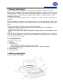
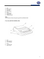
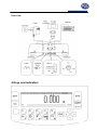
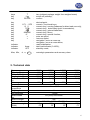
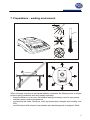
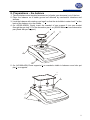
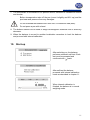
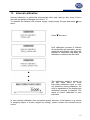
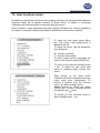
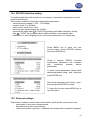
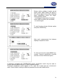
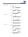
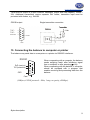
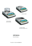
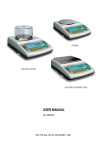
www.pce-industrial-needs.com Tursdale Technical Services Ltd Unit N12B Tursdale Business Park Co. Durham DH6 5PG United Kingdom Phone: +44 ( 0 ) 191 377 3398 Fax: +44 ( 0 ) 191 377 3357 [email protected] http://www.industrial-needs.com/ Manual PCE LS 500 / PCE-LS 3000 [email protected] 1. General description ............................................................................................................. 3 2. Completeness...................................................................................................................... 3 3. Balance description ............................................................................................................. 3 4.Keys and indicators .............................................................................................................. 5 5. Technical data ..................................................................................................................... 6 6. Security rules ....................................................................................................................... 7 7. Preparations – working environment ................................................................................... 8 8. Preparations – the balance .................................................................................................. 9 9. Operation principles ........................................................................................................... 10 10. Start-up........................................................................................................................... 11 11. Internal calibration .......................................................................................................... 12 12. User functions menu ........................................................................................................ 13 12.1 Autotaring ........................................................................................................... 14 12.2 Pieces counting function .................................................................................... 15 12.3 External calibration / calibration options .......................................................... 16 12.4 RS-232C interface setting ............................................................................... 20 12.5 Print-out settings ............................................................................................. 20 12.6 Date and time setting ...................................................................................... 24 12.6 LCD settings .................................................................................................... 25 12.8 Language setting (option) ................................................................................ 26 12.9 Weigh summing (option) ................................................................................. 27 12.10 Maximal /minimal value (option) .................................................................. 28 12.11 Treshold signalization (option) .................................................................... 29 13. Connecting the balance to computer or printer ................................................................ 32 14. Troubleshooting and maintenance .................................................................................. 33 Declaration of Conformity ...................................................................................................... 35 2 [email protected] 1. General description AG series balances are destined for high accuracy weighing in laboratory practice. Balances are equipped with internal calibration system for proper accuracy control during operation. The user should also own weight standard of OIML F2 or F1 class for periodical control of the balance (weight value stated in Technical Data sheet) available for extra fee. All balances are metrologically tested - calibration or legal verification certificate on demand. Legal verification is required for balances used in some applications: direct sale, pharmaceutical prescriptions, medical and pharmaceutical analysis, goods packing and others. Balances with legal verification are mark with the following: - protective seal placed on the casing mounting screw at the back of the balance, - calibration switch protective seal, - notified body stamps and green metrological marking placed on the balance name plate. PCE LS series balances are destined for purposes where verification is not required. PCE LS series balances do not have internal calibration system and also all functions connected with it are removed. 2. Completeness A standard set consist of: 1. Balance 2. Pan elements: - AG50-AG600 (round pan): a pan base and a pan, - AG1000-AG4000, AG8 (rectangular pan): gum nuts (4pcs) and a pan, 3. Feeder (ZN12V/500mA) 4. User manual 5. Guarantee Card 3. Balance description Front view (AG100-AG600) 3 [email protected] 1 – pan 2 – pan support 3 – pan ring 4 – LCD display 5 – keys 6 – rotating legs 7 – water level 8 – antiblast shield Note: AG600 does not have the pan ring and the antiblast shield. Front view (AG1000-AG4000, AG8) 1 – pan 2 – pan supports 4 – LCD display 5 – keys 6 – rotating legs 7 – water level 4 [email protected] Rear view: 4.Keys and indicators 5 [email protected] keys key key T I/ ENTER - tare (subtract package weight from weighed mass) switch-off (standby), confirm key key key key key key key key key key . 1/F1 ... 5/F5 6/ 0 7/ 8/ 9/MENU 0/ > < - decimal point, numeric / functional keys, numeric key / zeroing (balances for direct sale use only), numeric key / data output (print / transmission), numeric key / internal calibration, numeric key / Menu, numeric key / special function, enter an option, leave an option, navigation / move a cursor up, navigation / move a cursor down, result stabilisation, tatal load indicator (0-100%), stand-by mode, - metrologic parameters and accuracy class. indicator indicator indicator Max, Min, linear OFF d, e, II 5. Technical data Type Capacity (Max) Min load (Min) Reading unit (d) Verification unit (e) Tare range Accuracy class Working temperature Weighing time Pan dimension Balance base dim. Balance weight Power Calibration weight (OIML) AG100 100g 0,02g 0,001g 0,01g -100g AG200 200g 0,02g 0,001g 0,01g -200g II +18 ÷ +33°C AG300 300g 0,02g 0,001g 0,01g AG500 500g 0,02g 0,001g 0,01g -300g -500g <8s 115mm 215(235)x345x90mm 5kg ~230V 50Hz 6VA / =12V 300mA 100g 200g 200g F2 F2 F2 500g F1 6 [email protected] Type Capacity (Max) Min load (Min) Reading unit (d) Verification unit (e) Tare range Accuracy class Working temperature Weighing time Pan dimension Balance base dim. Balance weight Power Calibration weight (OIML) AG600 600g 0,5g 0,01g 0,1g AG100 1000g 0,5g 0,01g 0,1g AG200 2000g 0,5g 0,01g 0,1g -600g -1000g -2000g 150mm 500g F2 AG300 3000g 0,5g 0,01g 0,1g AG4000 4000g 0,5g 0,01g 0,1g AG8 8000g 5g 0,1g 1g -3000g II +18 ÷ +33°C -4000g -8000g <5s 165x165mm 215(235)x345x90mm 5kg ~230V 50Hz 6VA / =12V 300mA 1000g 2000g F2 F2 5000g F2 6. Security rules To avoid electrical shock or damage of the balance or connected peripheral devices, it is necessary to follow the security rules below. • All repairs and necessary regulations can be made by authorised personnel only. • To avoid fire risk use a feeder of an appropriate type (supplied with the balance). Pay attention that supply voltage is compatible with specified technical data. • Do not use the balance when its cover is opened. • Do not use the balance in explosive conditions. • Do not use the balance in high humidity. • If the balance seems not to operate properly, unplug it from the mains and do not use until checked by authorised service. 7 [email protected] 7. Preparations – working environment +33°C +18°C When choosing a location to set up the balance, remember the following rules to ensure proper working conditions and user-friendly operating: - setup the balance on an even, flat surface leaving neccesary room for easy acces, - maintain proper working temperature, - avoid strong air drafts, vibrations, dust, big temperature changes and humidity over 90%, - avoid locations with extreme heat radiation and electromagnetic or magnetic fields. 8 [email protected] 8. Preparations – the balance 1. Take the balance and supplied accessories (a feeder, pan elements) out of the box. 2. Place the balance on a stable ground not affected by mechanical vibrations and airflows. 3. Level the balance with rotating rear legs 6 so that the air bubble in water-level 7 at the back of the balance is in the middle. 4. (for AG100-AG600) Gently insert the mandrel of pan support 2 into pan socket through the pan ring 3. Put the decorative pan 1 on (AG600 balances have decorative pan joined with pan support). 1 2 3 7 6 5. (for AG1000-AG8) Place supports 2 on mandrels visible in balance cover hole put pan 1 on supports. 1 2 7 6 9 [email protected] 6. Plug a feeder to the power socket at the back of the balance. Moisture in the air may condense on the surface of the balance when transferred to the warmer environment. In this case leave the balance for at least 4 hours unplugged from the mains for conditioning to avoid wrong operating or damage of the balance. Leave the pan empty and plug the feeder to the mains. At the end of self-tests, the balance displays zero indication and is now ready to work. 9. Operation principles 1. To ensure proper weighing accuracy the balance is equipped with internal calibration system. The system automatically calibrates the balance every 2 hours and with temperature changes (more than 1°C) without user ingerence. Nevertheless, it is advised to check balance accuracy with weight standard (or other object with known weight) before and after each series of measurements. 2. Weighed sample should be placed in the centre of the pan. 3. In direct sale use (d=e), make sure that zero indicator is displayed. If not, press 0 key and wait until zero indication and zero indicator appears. In other balances the key does not operate. 4. The balance is equipped with a tare equal to its range. To tare the balance press →T← key. Storing a tare value does not extend measuring range, but only subtracts it from a load placed on a pan. To make weight control easier and to avoid range overdrawing, the balance is equipped with a load indicator (graduated in percentages). 5. Weighing result should be read when the indicator " stabilisation of a result. " lights, which signalises 6. When the balance is not used but it is necessary to be ready to work immediately, it can be switched off by pressing I/ key. The balance reading system is then switched off to "standby" mode (signalled by the indicator "OFF"). To switch the balance on press I/ key. The balance is immediately ready to operate maximum accuracy (after self tests). 10 [email protected] 7. The mechanism of the balance is a precise device, sensitive to mechanical strokes and shocks. Before transportation take off the pan (move it slightly and lift it up) and the pan base and preserve from any damages. Do not overload the balance more then 20% of maximum load (Max). Do not press a pan with a hand. 8. The balance should not be used to weigh ferromagnetic materials due to accuracy decrease. 9. When the balance is moved to another localisation remember to level the balance and proceed with internal calibration. 10. Start-up After switching-on, the balance performs automatic self-test. Each test must be accepted and confirmed with mark. No se puede mostrar la imagen. Puede que su equipo no tenga suficiente memoria para abrir la imagen o que ésta esté dañada. Reinicie el equipo y , a continuación, abra el archiv o de nuev o. Si sigue apareciendo la x roja, puede que tenga que borrar la imagen e insertarla de nuev o. After self-test the balance proceeds with internal calibration mode as described in chapter 11. When internal calibration is finished, the balance is in normal weighing mode. 11 [email protected] 11. Internal calibration Internal calibration is performed automatically after each start-up, also every 2 hours and with temperature changes more than 1°C. To calibrate the balance with internal weight, simply empty the pan and press key twice. Press key twice. Until calibration process is finished do not perform any operation, as any vibrations and shocks may affect the process of calibration and delay the calibration or deteriorate the result. The calibration weight is placed on the pan three times to avoid inaccurate calibration result. In case any problems during calibration, the error is signalised on the display and calibration process is stopped. The result of correct calibration is zero indication. In case internal calibration does not ensure proper accuracy of the balance (e.g. results of weighing object of known weight are wrong), please contact the nearest service centre. 12 [email protected] 12. User functions menu All balances, beside basic functions like weighing and tare, are equipped with additional functions. Basic set of special functions is shown below. In respect of metrology calibration with external weight is important special function. Other functions: recipe ingredients summing, density calculation etc. can be enabled as an option on customer request (described in additional brochure when ordered). To enter the user menu press Menu key. The cursor (dark background) is placed at the top. To move the cursor, use the navigation keys:▼and ▲. - function activated - function deactivated To enter chosen function and open the menu of the function press ENTER key. To return to the previous window press < key. To leave the user menu and return to weighing mode choose Exit option. Easy access to the most useful functions will shorten operation time and make work more comfortable. To remove a function from the function menu, use Menu settings option. Select function by cursor and press ENTER key. Chosen functions should be signified with mark. No se puede mostrar la imagen. Puede que su equipo no tenga suficiente memoria para abrir la imagen o que ésta esté dañada. Reinicie el equipo y , a continuación, abra el archiv o de nuev o. Si sigue apareciendo la x roja, puede que tenga que borrar la imagen e insertarla de nuev o. To quickly go from functions menu to Menu settings press key. 13 [email protected] 12.1 Autotaring This function automatically keeps zero indication when a pan is empty or zero indication was forced with →T← key. Press Menu key to enter the user function menu, choose Autotaring and press ENTER key. Choose Correction range using ∨ and ∧ keys and press ENTER key. Enter maximum zero flow to be automatically corrected (choose between 0.5 ÷ 5 verification unit(s) per second). Choose Activate ENTER. option and press Any changes off the zero readout that are equal to a defined fraction of digits per second are automatically tared, independently of changing environment conditions (temperature, humidity, etc.). To leave the function press Menu key, choose Autotaring function and then choose Deactivate option. 14 [email protected] 12.2 Pieces counting function 1. Counting with a reference sample Place a reference sample with known number of pieces on the pan. Press Menu key to enter the user function menu, choose Counting with the cursor and press ENTER key. Chose Pieces quantity option and press ENTER key. Using numeric keys enter the quantity of the sample and press ENTER key. The balance calculates unit weight basing on given number of pieces and reference sample weight and then shows number of pieces on the display. Reference sample parameters may be used in series of weighing. To recall previously used sample parameters start Counting function with Activate option. To leave the function press Menu key, choose Counting function and then choose Deactivate option. Note: To switch between weighing mode and pieces counting mode press key. 15 [email protected] 2.Counting with unit weight. Press Menu key to enter the user function menu, chose Counting and press ENTER key. Chose Unit weight option and press ENTER key Enter unit weight value using numeric keys and press ENTER to accept. The unit weigh value is stored in balance memory until switched off. The balance displays pieces amount. Note: To correct wrong digits when entering unit weight, press < key to delete the last number or CLR to leave the function and proceed from the beginning. 12.3 External calibration / calibration options Calibration with external weight standard in verified balances should be performed in case balance indications exceed permissible error. To calibrate the balance a service centre should use calibration weight as stated in Technical Data table (or of better accuracy) with valid calibration certificate. Calibration of EC verified balance requires to destroy a mark for protecting an access to adjustment switch and results in loosing its EC verification. To renew EC verification of a balance, contact with service or notified body is necessary. 16 [email protected] Adjustment switch ON Mark OFF In EC verified balances executing a calibration requires to change adjustment switch position, which is placed behind the mark (sticker) of a notified body. An access to the switch is possible only after the mark is removed, which causes loosing EC verification of the scale. To renew EC verification of a balance, contact with service or notified body is necessary. In order to store results of calibration with external weight it is possible to print calibration report (see Calibration options). For this purpose a printer or a computer with testing program is necessary. The report printout example Date : ... Time: ... Calibration report -------------------------------Date of production: ... - external weight value registered during factory calibration Serial number: ... Program version: ... - internal weight value registered during factory calibration Adjustment no.: ... Factory external weight: ... Factory internal weight: ... Current external weight: ... - external weight value registered during last calibration - internal weight value registered during last external calibration - difference between internal weight values: factory value–current value Current internal weight: ... Weight difference: ... Calibration options: 17 [email protected] If an access to adjustment switch is not protected with the mark, with a thin screwdriver set adjustment switch to ON position (balance displays the message Calibration switch ON and makes a sound). Press MENU key choose Calibration option and press ENTER. Option External weight enables to enter the value of used calibration weight. Choose External weight option, press ENTER and use > and < keys to select desired value. It is advised to use as great weight value as possible. Calibration of time and Calibration of temperature option is related with internal calibration. To print a calibration report, connect a printer and use Report printout option. Calibration report is a proof of correct calibration process and may be useful for balance diagnostics. 18 [email protected] Calibration sequence: Press Menu key, choose Calibration option and press ENTER to accept (calibration must be enabled). Check if External weight value is equal to external weight value used for calibration. If not, choose External weight option and enter correct value. Choose External calibration option and press ENTER to accept. Wait until taring process is finished and load the pan with the calibration weight of correct value. Take off the calibration weight. Wait until external calibration is finished. After external calibration the balance switches to the weighing mode. 19 [email protected] 12.4 RS-232C interface setting To enable cooperation with a printer (or a computer), transmission parameters must be equal in both devices. This function enables the following transmission parameters: - send and receive speed (1 200 ÷ 115 200bps), - number of bits (7 or 8 Bytes), - parity control (none, even, odd), - protocole type (default protocole - LONG), - transmission mode (after / PRINT key pressing with stable indication, directly after / PRINT key pressing without stable indication, automatically after stabilisation of each weighing result, continuous transmission in 0,1s periods). Press MENU key to enter the user function menu, choose RS232C settings and press ENTER key. Check if balance RS232C interface transmission parameters are compliant with connected external device parameters. To enter correct parameters values select desired parameter using ∨ and ∧ keys and press ENTER key. Set correct parameter value using < and > keys and press ENTER to accept. To leave the function press MENU key or use Exit option. 12.5 Print-out settings This function enables to select desired information, which will be used on print-outs: - numeration of succesive measurements, - date and time of each measurement, - custom information (optional) – additional text entered with a computer keyboard. 20 [email protected] Press MENU key to enter the user function menu, choose Print settings and press ENTER key. Select desired parameter using ∨ and ∧ keys and press ENTER key to change setting. Header - the entrance to the printout header definition menu; the checkbox sign indicates if at least one option in the header definition menu is marked. Header definition menu Relevant element is marked/unmarked if ENTER key is pressed. The marked element will appear in a printout header if the Header element in values definition menu is marked. An example of a full printout header: --------------- WEIGHING --------------Date : 2000-04-25 Time : 22:32 Scale type : AGNZ200 Serial number : 123456 ID1 string ID2 string ID3 string ← blank line ← mode name ← date and time ← balance type ← serial number ← ID1 ← ID2 ← ID3 21 [email protected] ← signature Signature ..................................... Values - the entrance to printout values definition menu; the checkbox sign indicates if at least one option in values definition menu is marked. Values definition menu Relevant element is marked/unmarked if ENTER key is pressed. The values Tare, Net and Gross are always expressed in grams. The value LCD result always indicates display state with an active unit. An example of a full printout header (without header): ID1 string ID2 string ID3 string Measurement number : 1 T 0.0000 g N 66.7425 g B 66.7425 g LCD 333.7125 ct ← blank line ← ID1 ← ID2 ← ID3 ← measurement number ← tare ← net ← gross ← LCD result 22 [email protected] Footer - the entrance to the printout footer definition menu; the checkbox sign indicates if at least one option in footer definition menu is marked. Footer definition menu Relevant element is marked/unmarked if ENTER key is pressed. An example of a full printout footer : ------------ PCS COUNTING ------------Date : 2000-04-25 Time : 23:05 Scale type : AGNZ200 Serial number : 123456 ID1 string ID2 string ID3 string Signature ..................................... --------------------------------------- ← blank line ← mode name ← date and time ← balance type ← serial number ← ID1 ← ID2 ← ID3 ← signature ← separating line ← 3 empty lines ID1, ID2, ID2 - strings (max. 20 characters) defined by PS2 keyboard or by a scale numeric keypad, which works similarly to mobile keyboard (characters coupled with relevant key appear in a display first line after the key is pressed); inscribed string is approved with ENTER key. 23 [email protected] 12.6 Date and time setting Use this function to set current date and time, used in print-outs: Press MENU key to enter the user function menu, choose Time&date settings and press ENTER key. Select desired parameter using ∨ and ∧ keys and press ENTER. Enter correct values using numeric keys and press ENTER to accept. 24 [email protected] 12.6 LCD settings This function enables to set contrast and back-light illumination of the LCD display: Press MENU key to enter the user function menu, choose LCD settings and press ENTER key. Choose Contrast option using ∨ and ∧ keys and press ENTER to key. Select desired Contrast value using < and > keys and press ENTER accept. Choose Backlight option using ∨ and ∧ keys and press ENTER key. Turn LCD Backlight on or off and press ENTER to accept. 25 [email protected] 12.8 Language setting (option) This function enables to select a language used for displayed commends and printouts: Press MENU key to enter the user function menu, choose Language settings and press ENTER key. Select desired language using ∧ and ∨ keys and press ENTER key to accept 26 [email protected] 12.9 Weigh summing (option) This function allows separate weighing of several ingredients in one container with a possibility to control aggregated sum of all weighed components. Press Menu key, choose Weighs summing and press ENTER to accept. Chose Activate option using ∨ and ∧ keys and press ENTER. The balance is now ready for successive ingredients weighing. Before weighing each ingredient press →T← key to zero the indication. During series weighing total weight (Σ) and number of series (n) are shown at the left of the display. For instant return to weighing mode and display total weight of all ingredients press key. To return to series summation press the key again. To leave the function press Menu key, chose Weigh summing function and then chose Deactivate option. 27 [email protected] 12.10 Maximal /minimal value (option) This function enables to display a maximal or minimal value of series of weighing. Press Menu key, choose Maximal/minimal value and press ENTER to accept. Choose Activate option using ∨ and ∧ keys and press ENTER. The function is now active – the balance displays only maximum value from successive series of weighing (starting from the function activation or using Reset option). To display weigh value of a current sample press key. To return to Maximum value function press the key again. To leave the function press MENU key, choose Maximal/minimal value function and then chose Deactivate option. 28 [email protected] 12.11 Treshold signalization (option) This function compares weighing result with two reference values: lower and upper threshold. The balance signalises comparison result with MIN, OK and MAX indicators and sound signal. If comparison result is: - smaller than lower threshold – the balance displays MIN, - between threshold values - the balance displays OK, - bigger than upper threshold - the balance displays MAX - lower than zero threshold (no load) – none of the indicators appears Operation sequence: Press MENU key, choose Treshold signalization option and press ENTER to accept. Chose Zero threshold option using ∨ and ∧ keys and press ENTER. Enter Zero threshold value using decimal keys and press ENTER key – indications below this value are regarded as unloaded balance (threshold indicators does not appear). Enter MIN threshold and MAX threshold values. Outputs mode enables to set THRESHOLD output working mode (described further). To choose appropriate working mode use < and > keys and press ENTER key to accept. 29 [email protected] Buzzer option enables to select sound signal mode. When Stable OK option is set, sound signal occurs after weighing result stabilisation within OK range. Other possible options: - sound signal occurs when threshold values (MIN and MAX) are exceeded, - no sound signal To start function choose Activate option and press ENTER key. After each measurement the balance displays comparison result. To leave the function press MENU key, choose Treshold signalization function and then choose Deactivate option. In balances equipped with THRESHOLD output, comparison result may be used to control external optical indicator or other external devices. Threshold comparison results appear on Thr I and Thr II output pins as a shortcircuit state. Control output working modes are presented on the state charts below. 30 [email protected] THRESHOLD output state charts (increasing load): 1. Indicator mode: Outputs: P1 ( thr I) zero treshold thr I P2 (thr II) thr I thr II P3 (zero) thr II 2. Pulse mode: Outputs: 2s. P1 (thr I ) thr I 2s. P2 (thr II) thr II P3 (zero) zero treshold 3. Level mode: Outputs: P1 (thr I ) zero treshold thr I P2 (thr II) thr I thr II P3 (zero) thr II 31 [email protected] THRESHOLD output is a open collector transoptor output with load capacity 100mA / 24V. Additional transmitters require separate 24V feeder, transmitter input must be protected with diodes, e.g. 1N4148. PROGI output Single transmitter connection 13. Connecting the balance to computer or printer The balance may send data to a computer or a printer via RS232C interfacee. RS232C 1 RxD (receiver) TxD (transmitter) 2 3 4 5 GND 6 7 8 9 When cooperating with a computer, the balance sends weighing result after initialising signal from a computer or after pressing key. When cooperating with the balance, a computer should be equipped with a program that enables receiving and processing data from the balance. Case (16Bytes, LONG protocol - 8bits, 1stop, no parity, 4800bps) Bytes description: 32 [email protected] 1 2 3 4 5÷9 10 11 12 13 14 15 16 - „-„ mark or space - space - digit or space - digit, decimal point or space - digit - space - k, l, c, p or space - g, b, t, c or % - space - CR - LF 14. Troubleshooting and maintenance Display indication Possible cause Remedy "Test ..." Auto-tests are being performed / electronic unit damage The balance is during zeroing / mechanical damage wait for 1 minute "----" "Internal calibration: load error" „Tare range exceeded” „Zeroing range exceeded” „Weighing range exceeded” „Measuring range exceeded (+)” „Measuring range exceeded (+)” „Unit weigh is too small” wait for 1 minute check if the balance is placed on stable ground, not affected by vibrations Check if there are all necessary pan elements or if the balance is not loaded To small zero load or overloading of balance mechanism / mechanical damage Tare key pressed during zero Balance indications must be indication different than zero Permissible zeroing range was Remove the load from the pan exceeded Permissible weighing range Reduce the load (Max +9e) was exceeded Upper limit of analog-digital Remove the load from the pan transducer measuring range was exceeded Lower limit of analog-digital Check if there are all necessary transducer measuring range pan elements was exceeded Entered unit weigh is too small Unit weight is too small or entered number of pieces is too big If a remedy does not have any effect and the communicate is still displayed, contact your dealer or service centre. 33 [email protected] 1. A balance should be kept clean. 2. Take care that no dirt gets between the casing and the pan. If found any, remove a pan (lift it up), remove the dirt and then replace a pan. 3. In case of improper operation caused by a short-lasting power supply decay, unplug the balance from the mains and then plug it in again after few seconds. 4. It is forbidden to make any repairs by unauthorised persons. 5. To repair a balance, please contact our nearest service centre. 34 [email protected] Declaration of Conformity PCE-GROUP Europe Im Langel 4 D – 59872 Meschede E-Mail: [email protected] Tel: 0049-[0]2903- 976 99-0 Fax: 0049-[0]2903-976 99-29 Internet: www.pce-group-europe.com Konformitätserklärung Declaration of conformity for apparatus with CE mark Konformitätserklärung für Geräte mit CE-Zeichen Déclaration de conformité pour appareils portant la marque CE Declaración de conformidad para aparatos con disitintivo CE Dichiarazione di coformitá per apparecchi contrassegnati con la marcatura CE PCE-LS 1. EN 55022 standard Limits and methods of measurement of radio disturbance characteristics of information technology equipment and IEC 61000-4-3 Electromagnetic compatibility (EMC) - Part 4-3: Testing and measurement techniques Radiated, radio-frequency, electromagnetic field immunity test harmonized with the Council Directive 89/336/EEC (Electromagnetic compatibility directive). Additional information: Conformity evaluation for the Council Directive 89/336/EEC was carried out by Research Laboratory of Electrotechnology Institute. Date: 01.03.2006 Signature: PCE-GROUP Europe OHG Management In this direction will find a vision of the measurement technique: http://www.industrial-needs.com/measuring-instruments.htm NOTE: "This instrument doesn’t have ATEX protection, so it should not be used in potentially explosive atmospheres (powder, flammable gases)." 35