1
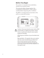
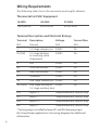
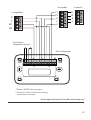
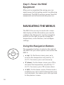
©2014 ecobee
477 Richmond St West | 2nd Floor,
Toronto | Ontario | M5V 3E7 | Canada
Toll free 1.877.932.6233
www.ecobee.com
EB-EMSSI-01-rev3
EMS Si
Manual
CONTENTS
GETTING STARTED 1
Welcome1
Technical Support
1
Before You Begin
2
HVAC System Compatibility
3
Approvals 4
FCC Compliance Statement
4
Specifications5
Wiring Requirements
6
INSTALLING THE EMS Si
Step 1. Power Off HVAC Equipment
Step 2. Remove Existing Thermostat
Step 3. Install the EMS Si
Step 4. Connect the Wiring
Step 5. Power On HVAC Equipment
7
7
7
7
9
20
NAVIGATING THE MENUS
Using the Navigation Buttons
20
20
CONFIGURING THE HVAC SETTINGS
22
Equipment22
Thresholds25
Test Equipment
29
Reset HVAC Equipment Settings
29
Performing a Hardware Reset
29
Rebooting the EMS Si
30
Configuring Reminders and Alerts
31
Alerts32
AUTOMATION34
Setting Up the Sensor Inputs
34
CONNECTING TO THE INTERNET
Setting Up WiFi
Configuring a Web Portal Account
40
41
42
USING YOUR EMS Si
44
System Mode
45
Fan45
Weather Forecast
47
Cleaning47
CONFIGURING YOUR EMS Si
48
Configuring Personal Preferences
48
Utility CPP Setting
54
WiFi55
Creating Your Weekly Schedule
56
Using the Weekly Schedule Editor
57
Scheduling a Calendar Event
58
3-YEAR LIMITED WARRANTY
61
END-USER SOFTWARE LICENSE AGREEMENT
62
GETTING STARTED
Welcome
The ecobee Energy Management System Si
(EMS Si) is the newest technology designed for
the commercial market. It is ideal in applications
where a simple programmable thermostat does
not provide adequate controls and functionality
and a full-scale building automation system is
too complex and cost prohibitive. The ecobee
EMS Si is user-friendly, reduces a building’s
operating costs, and delivers increased energy
conservation.
From their EMS Web Portal, users can remotely
monitor, identify, analyze and troubleshoot
performance issues; manage the temperature
and operational settings from a central location;
and take action without having to send a
technician on-site.
The ecobee EMS Si can maximize any building’s
efficiency, reduce energy consumption and
deliver significant cost savings.
Technical Support
Our technical support team is available to
answer your questions at 1.877.932.6233, or via
email at [email protected].
1
Before You Begin
This product is intended to be installed by
trained service professionals.
This manual explains the procedures for
installing the ecobee EMS Si. Please read it
carefully before beginning the installation.
The EMS Si is designed to be mounted on the
wall in a convenient location.
OK
MENU
BACK
ecobee
!
Caution: Disconnect electric power to the HVAC
system before installing this product. Failure
to do so could result in electric shock and/or
equipment damage.
All wiring must conform to your local electrical
code.
Mercury Notice: This product does not contain
mercury. If you are replacing a product that
does contain mercury, contact your local
waste-management authority for disposal
instructions. Do not discard the old product in
the regular trash.
2
HVAC System Compatibility
The EMS Si is designed to operate with lowvoltage heating and cooling systems. It is not
designed for use with line-voltage or millivolt
heating and cooling systems.
The EMS Si supports:
Up to 2 heat and 2 cool stages on a
conventional system.
Up to 3 heat and 2 cool stages on a heat
pump system.
The ecobee EMS Si supports the following
equipment:
Equipment Supported?
Gas/Oil/Electric heating
(up to two stages)
Yes
Heat pump with auxiliary heat
(up to three stages)
Yes
Geothermal Heat Pump
Yes
Dual fuel systems
Yes
Standard electric cooling
(up to two stages)
Yes
BoilersYes
2 remote sensor inputs (dry contact and/or
10K resistive temperature only)
Yes
3
Approvals
This product was designed and built in accordance
to RoHS directive 2002/95/EC and contains no
hazardous substances as defined by this directive.
FCC Compliance Statement
This equipment has been tested and found to
comply with the limits for Class B digital devices,
pursuant to Part 15 of the FCC Rules. These limits are
designed to provide reasonable protection against
harmful interference in a residential installation. This
equipment generates, uses, and can radiate radio
frequency energy and, if not installed and used in
accordance with the instruction manual, may cause
harmful interference to radio communications.
However, there is no guarantee that interference
will not occur in a particular installation. If this
equipment does cause harmful interference to radio
or television reception, which can be determined
by turning the equipment off and on, the user is
encouraged to try to correct the interference by one
or more of the following measures:
Reorient or relocate the receiving antenna.
Increase the separation between the equipment
and receiver.
Connect the equipment to an outlet on a different
circuit from the receiver.
Consult the dealer or an experienced radio/TV
contractor for help.
To satisfy FCC/IC RF exposure safety requirements,
a separation distance of 8 inches (20 cm) or more
should be maintained between this device and
persons. To ensure compliance, operation at closer
than this distance is not allowed.
4
FCC ID: WR9EBSTAT IC: 7981A-EBSTAT
Warning: Changes or modifications not expressly
approved by ecobee Inc. could void the user’s
authority to operate the equipment.
Specifications
Temperature ranges
Heat: Cool: Display: Sensitivity: Operating: 45 to 79 °F (7 to 26 °C)
45 to 92 °F (14 to 33 °C)
40 to 100 °F (5 to 37 °C)
+/- 1 °F (0.5 °C)
32 to 130 °F (0 to 55 °C)
Humidity Range
Display:
20 to 90% R.H.
Sensitivity: +/- 5% R.H.
Operating: 5 to 95% R.H (non-condensing)
Dimensions
Thermostat: 5.5”W x 3.25”H x 1”D
(139.5mm H x 82.5mm W x 25mm D)
Power
24 VAC (3VA maximum)
5
Wiring Requirements
The following table shows the maximum wire lengths allowed:
Thermostat to HVAC Equipment
18 AWG
20 AWG
22 AWG
128 ft/380 m
80 ft/240 m
50 ft/150 m
Terminal Description and Electrical Ratings
Terminal Description
Voltage
Current Max
N/CUnused
N/A
N/A
Y
1st stage compressor 24VAC
2A
W (O/B) 1st stage heating or reversing valve
changeover
24VAC
GFan
24VAC2A
RC
Cool transformer *
24VAC
2A
RH
Heat transformer *
24VAC
2A
C Common
Y2
2A
24VAC2A
2nd stage compressor 24VAC
2A
W2 (AUX) 2nd stage heating or 24VAC
1st stage auxiliary heat
2A
R1+
Input 1+
Temperature/dry contact only
R1-
Input 1-
Temperature/dry contact only
R2+
Input 2+
Temperature/dry contact only
R2-
Input 2-
Temperature/dry contact only
* Factory jumper installed between RC and RH. Remove jumper
for 2-transformer applications. See wiring diagrams for additional
information.
6
INSTALLING THE EMS Si
There are 5 steps to install the ecobee EMS Si:
Step 1. Power Off HVAC Equipment
Step 2. Remove Existing Thermostat
Step 3. Install the EMS Si
Step 4. Connect the Wiring
Step 5. Power On HVAC Equipment
Step 1. Power Off HVAC Equipment
Before disconnecting the existing thermostat, or installing the
EMS Si, disconnect the power to the heating and air conditioning
equipment.
Step 2. Remove Existing Thermostat
Disconnect the wires to the existing thermostat and remove
it from the wall (if you are installing the EMS Si in the same
location).
Step 3. Install the EMS Si
The ideal location for the thermostat is approximately 5 ft (1.5 m)
above floor level in the main living area.
Do not install the thermostat:
Close to sources of heat such as incandescent lights
Near supply heating/cooling sources
In direct sunlight
On exterior, non-insulated or poorly insulated walls
In the kitchen or other areas of potentially high heat and/or
humidity
In an area that could restrict air flow
7
To install the thermostat:
1. Gently separate the backplate from the thermostat.
2. Place the thermostat backplate on the wall. Make sure that
any existing wires can be inserted through the opening for the
wiring.
3. Using the backplate as a template, mark the location of the
mounting holes on the wall as shown below.
W2 Y2
R2- R2+ R1- R1+ AUX
C
RH
W
RC G O/B
Y
N/C
The solid color indicates mounting holes
4. Move the backplate out of the way and make holes where
indicated in step 3. The mounting holes can accommodate a #6
pan-head screw. It is recommended to use the included fasteners
to ensure proper fitting of the front housing.
5. Use the included drywall plugs (or other suitable anchors) to
ensure the thermostat can be mounted securely to the wall.
6. Fasten the backplate to the wall using the screws provided (or
other suitable screws).
8
Step 4. Connect the Wiring
You need to use low-voltage cable to connect the thermostat to the HVAC
equipment. Check the wiring diagrams on pages 10 to 19 for the number of
wires required.
Note: There is a factory installed jumper between R/H and R/C. Ensure any
unused wires do not have exposed bare copper conductors.
To connect the thermostat to the equipment:
1. Connect the wires as shown in the wiring diagrams.
2. Attach the EMS Si to the backplate. Ensure that the pins on the
thermostat align with the terminal block on the backplate.
Wiring Diagrams
The following diagrams show how to connect the thermostat terminals to
various HVAC equipment.
9
1-stage Furnace
Y
W
G
R
HUM
C
1-stage AC
24V
C
Dry Contact /
Temperature Sensors
EMS Si Thermostat
W2 Y2
R2- R2+ R1- R1+ AUX
C
RH
RC
W
G O/B
Y
N/C
Single stage heat/cool
10
1-stage Furnace
Y
W
G
R
HUM
C
2-stage AC
Y1
Y2
R
C
Dry Contact /
Temperature Sensors
EMS Si Thermostat
W2 Y2
R2- R2+ R1- R1+ AUX
C
RH
RC
W
G O/B
Y
N/C
Single stage heat, dual stage cool
11
2-stage Furnace
Y1
W1
G
W2
R
Y2
1-stage AC
24V
HUM
C
C
Dry Contact /
Temperature Sensors
EMS Si Thermostat
W2 Y2
R2- R2+ R1- R1+ AUX
C
RH
RC
W
G O/B
Y
N/C
Dual stage heat, single stage cool
12
2-stage Furnace
Y1
W1
G
W2
R
Y2
2-stage AC
Y1
Y2
R
C
HUM
C
Dry Contact /
Temperature Sensors
EMS Si Thermostat
W2 Y2
R2- R2+ R1- R1+ AUX
C
RH
RC
W
G O/B
Y
N/C
Dual stage heat, dual stage cool
13
Air Handler
1-stage Heat Pump
O
O
W
Y/Y2
G
R
W2
Y
R
C
C
Dry Contact /
Temperature Sensors
EMS Si Thermostat
W2 Y2
R2- R2+ R1- R1+ AUX
C
RH
RC
W
G O/B
Y
N/C
Single stage heat pump with auxiliary heat
14
2-stage Heat Pump
Air Handler
O
O
Y1
W2
Y2
R
C
W
Y/Y2
G
R
C
Dry Contact /
Temperature Sensors
EMS Si Thermostat
W2 Y2
R2- R2+ R1- R1+ AUX
C
RH
RC
W
G O/B
Y
N/C
Dual stage heat pump with auxiliary heat
15
Air Handler
Y1
Y2
R
C
G
Boiler
R
1-stage AC
24V
C
C
W
Dry Contact /
Temperature Sensors
EMS Si Thermostat
W2 Y2
R2- R2+ R1- R1+ AUX
C
RH
RC
W
G O/B
Y
N/C
* Remove RH/RC factory jumper
C terminal to be connected to heating
transformer common
Boiler with air handler and single-stage cool
16
Air Handler
Y1
Y2
R
C
G
2-stage Boiler
R
C
W2
W1
1-stage AC
24V
C
Dry Contact /
Temperature Sensors
EMS Si Thermostat
W2 Y2
R2- R2+ R1- R1+ AUX
C
RH
RC
W
G O/B
Y
N/C
* Remove RH/RC factory jumper
C terminal to be connected to heating
transformer common
Dual stage boiler with air handler and single stage cool
17
2-stage AC
Air Handler
Y1
Y2
R
C
G
Boiler
R
C
W
Y1
Y2
R
C
Dry Contact /
Temperature Sensors
EMS Si Thermostat
W2 Y2
R2- R2+ R1- R1+ AUX
C
RH
RC
W
G O/B
Y
N/C
* Remove RH/RC factory jumper
C terminal to be connected to heating
transformer common
Single stage boiler with air handler, dual stage cool
18
2-stage AC
Air Handler
Y1
Y2
R
C
G
2-stage Boiler
R
C
W1
W2
Y1
Y2
R
C
Dry Contact /
Temperature Sensors
EMS Si Thermostat
W2 Y2
R2- R2+ R1- R1+ AUX
C
RH
RC
W
G O/B
Y
N/C
* Remove RH/RC factory jumper
C terminal to be connected to heating
transformer common
Dual stage boiler with air handler, dual stage cool
19
Step 5. Power On HVAC
Equipment
After you’ve completed the wiring, you can
apply power to the heating and air conditioning
equipment. The EMS Si receives power from the
equipment and will automatically power on.
NAVIGATING THE MENUS
The EMS Si has an easy-to-read color screen
that displays all the information you need to
configure the thermostat. Use the navigation
buttons on the right to quickly change the
temperature, access features, and configure
settings.
Using the Navigation Buttons
OK
The navigation buttons located on the right of
the EMS Si let you select options and control the
EMS Si.
▲ (up) On the Home screen, press ▲ to
increase the temperature set point by 1°F
(0.5°C). For menus, press ▲ to move up.
▼ (down) On the Home screen, press ▼ to
decrease the temperature set point by 1°F
(0.5°C). For menus, press ▼ to move down.
◀ (left) On the Home screen, if Auto mode is
enabled, press ◀ to switch between heat and
cool set points. For menus, press ◀ to go back
to the previous screen.
20
▶ (right) On the Home screen, if Auto mode
is enabled, press ▶ to switch between heat
and cool set points. For menus, press ▶ to
choose the currently highlighted option.
OK On a menu screen, press OK to choose
the currently highlighted option. If a
configuration option is selected, pressing OK
will keep its new value and return back to the
previous screen.
MENU Pressing MENU displays a list of all
available options. If a menu is currently
displayed, pressing MENU will cancel any
unsaved changes and return to the Home
screen.
BACK On a menu screen, press BACK to go
back to the previous screen.
MENU
BACK
On-Screen Keyboard
If you need to type in any information, an onscreen keyboard will appear. To enter a letter or
number, move to the character by pressing the
arrow keys and then press OK to select it.
Select
to enter capital letters; select
to enter commonly used symbols. If you
make a mistake, press
to delete the text .
To keep your changes, select
your changes, press BACK.
. To cancel
21
CONFIGURING THE HVAC
SETTINGS
The first step after installing the EMS Si is to
configure the settings for the various devices
(such as a furnace or air conditioner) that are
being connected.
Equipment
To configure the
equipment settings:
The Equipment settings let you configure the
devices connected to the thermostat.
From the Home screen,
press MENU.
Heat Pump
Select Settings ▶
Installation Settings.
This section lets you configure a heat pump with
up to 2 heat/2 cool stages plus an auxiliary heat
source.
Select Equipment.
Configure the devices
connected to the EMS Si.
Geothermal heat pump Select Yes if you are
using a geothermal heat pump. This helps the
thermostat determine optimum performance
and default settings. If you select No, the
system will optimize the settings for an air-toair heat pump.
OB energize on cool If you choose Yes, the
reversing valve output (O/B terminal) will
activate when there is a call for cooling. If you
select No, the relay will activate when there is
call for heat.
Min Cycle Off Time Configures the minimum
compressor off time between cycles (240 to
900 seconds).
Min Outdoor Temp Disables the compressor
when the outside air temperature reaches the
configured minimum setting. This performs
two functions. It prevents the compressor
22
from running when the outdoor temperature
is too low, thus resulting in damage to the
compressor. You can also set this value to
determine when you want the auxiliary heat
(if installed) to engage to help meet the
set temperature. The temperature range is
adjustable from 0 to 65 °F (–17.8 to 18.3 °C) or
can be completely disabled. Note: You need
an internet connection for this feature to
operate properly.
Allow HP with Aux Heat If you select Yes
and there is a source of auxiliary heat, it will
turn on in addition to the heat pump. The
heat pump will be energized for the first 30
minutes. If, after 30 minutes, the set point
has not been met, the auxiliary heat will be
energized to assist the heat pump in meeting
the load.
If you select No, the heat pump will be
energized for up to 2 hours. If after 2 hours the
set point has not been met, the thermostat
will shutdown the heat pump and energize
the auxiliary heat to meet the set point. This
option should also be used for installation
where the heat pump evaporator coil is
downstream from the source of auxiliary heat.
This setting is only available the Comp to
Aux Temp Delta and Comp to Aux Runtime
settings are both set to Auto (default)
23
Furnace
Allows you to enable and configure up to a
2-stage conventional heat source. If you have
selected a heat pump as your primary source,
this feature allows you to configure the 1st stage
of auxiliary heat connected to the system.
Furnace Type Allows you to configure the
type of furnace. This helps the thermostat
optimize its algorithms based on the type
of fuel and typical characteristics of the
chosen system. Choose the option that
best represents the type of heating system
installed.
Heat Fan Control Configures the furnace fan
to be controlled by the EMS Si or the HVAC
system during heat cycles. Normally the HVAC
system controls the fan during heat cycles.
Air Conditioner
Configures up to 2 stages of air conditioning. If
you require a second stage, you must enable the
Y2 relay.
24
Thresholds
This section configures the temperature and
time thresholds associated with the heating and
cooling equipment.
You must configure the Equipment settings
(page 25) before setting the thresholds.
Only the applicable threshold settings will be
displayed (i.e. if no air conditioner is configured,
you will not see the options related to air
conditioners).
Allow Auto Heat/Cool
To configure threshold
settings:
From the Home screen,
press MENU.
Select Settings ▶
Installation Settings.
Select Thresholds.
Configure the
temperature threshold
settings.
Enabling this option allows the user to select
auto change-over as a system mode.
Heat/Cool Min Delta
The minimum difference between the heat
mode set temperature and the cool mode set
temperature when the system mode is in auto
change-over. The delta is adjustable from 2 to 10
°F (1.1 to 5.5 °C). The default value is 5 °F (2.8 °C).
Compressor Settings
Min Cycle Off Time Configures the
compressor off time between cycles. This
ensures the compressor does not short cycle
(which could affect the operating life of the
system). This time is adjustable from 240–900
seconds.
Min Outdoor Temp Configures the minimum
outside air temperature at which the
compressor will be disabled. This performs
two functions. It prevents the compressor
from running when the outdoor temperature
is too low, thus resulting in damage to the
compressor. You can also set this value to
25
determine when you want the auxiliary heat
(if installed) to engage to help meet the
set temperature. The temperature range is
adjustable from 0 to 65 °F (–17.8 to 18.3 °C) or
can be completely disabled. Note: You need
an internet connection for this feature to
operate properly.
AC Overcool Max When using the AC to
dehumidify, the setting configures how
many degrees below the current set point
the thermostat will run in order to decrease
humidity. Options are Disabled (default) or
from 0.5 to 5 °F (0.3 to 2.8 °C).
Aux Heat Settings
Max Outdoor Temperature Configures the
maximum outdoor temperature threshold.
Above this level, the auxiliary heat will not
be activated. The temperature is adjustable
from 0 to 80 °F (26.5 °C) in increments of 0.5°F
(0.3°C). The default value is 70°F (21°C).
Common Heat/Cool Settings
Heat Differential Temp The minimum
difference between the current temperature
and set temperature before the system calls
for heat. A smaller difference means shorter
cycle times, whereas a larger difference results
in longer cycle times. The temperature range
is adjustable form 0 to 3 °F (-17.5 to 26.5 °C) in
0.5°F (0.3°C) increments.
Heat Dissipation Time The amount of time
the fan will run after the heat set point has
been reached and the call for heat has been
turned off. Running the fan for a period of
time allows for any heated air left in the ducts
to circulate throughout the building. The
26
time is adjustable from 0 to 900 seconds. The
default value is 30 seconds.
Cool Differential Temp The minimum
difference between the current temperature
and set temperature before the system calls
for cool. A smaller difference means shorter
cycle times, whereas a larger difference results
in longer cycle times. The temperature range
is adjustable from 0 to 3 °F (0.3 to 1.7 °C) in
0.5°F (0.3°C) increments.
Cool Dissipation Time The amount of time
the fan will run after the cool has been turned
off. Running the fan for a period of time
allows for any cooled air left in the ducts to
circulate throughout the building. The time is
adjustable from 0 to 900 seconds. The default
value is 30 seconds.
Advanced Settings
These options customize how long each stage
will run before the next stage turns on. You may
also program when a particular stage is turned
on based on the temperature delta between the
set temperature and the current temperature.
Reverse Staging If enabled, the thermostat
will cycle down from the higher stages so
that as it approaches set point it will only be
running in stage 1. The HVAC equipment will
start in stage 1. As the stage 1 temperature
delta is exceeded, the second stage will
engage. Once the equipment has brought
the current temperature back to within the
heat or cool differential setting, stage 2 will
disengage and stage 1 will remain running
until the set point is meet.
Stage 2 Temp Delta The minimum difference
27
between the current temperature and the set
temperature that will activate the auxiliary
heat (regardless if the maximum run time of
the previous stage was reached). Options are
Auto (default) and 1 to 10 °F (0.6 to 5.6 °C).
Stage 1 Max Runtime The maximum amount
of time stage 1 will run before engaging the
next stage. Options are Auto (default) and 10
to 120 minutes.
Comp to Aux Temp Delta The maximum
amount of time this stage will run before
engaging the next stage. Options are Auto
(default) and 1 to 10 °F (0.6 to 5.6 °C).
Comp to Aux Runtime The minimum
difference between the current temperature
and the set temperature that will activate this
stage (regardless if the maximum run time of
the previous stage was reached). Options are
Auto (default), Disabled, and 1 to 10 °F (0.6 to
5.6 °C).
Cool Min On Time Sets the minimum
equipment run time in cool mode: 1 to 20 min
(default is 5 min).
Heat Min On Time Sets the minimum
equipment run time in heat mode: 1 to 20 min
(default is 5 min).
Temp Correction
Lets you program an offset between the real
temperature at thermostat and the displayed
temperature. If you find that the temperature
where the thermostat is located does not
represent the room temperature, change the
offset to compensate for the difference. The
correct temperature is adjustable from +/- 10°F
in 0.5°F (0.3°C) increments.
28
Installer Code
To prevent accidental modifications to the
installation settings, you can enable a 4-digit
installer code. This code is pre-programmed to
3262.
Test Equipment
These options let you test the wiring and
connections of the devices connected to the
thermostat by turning them on or off.
To test the equipment:
The equipment will turn off when you exit the
menu.
Select Settings ▶
Installation Settings.
!
Warning: Compressor protection and
minimum run-time features are not
enforced while in this mode.
From the Home screen,
press MENU.
Select Test Equipment.
Select OK.
Test the equipment
connected to the
thermostat by turning each
component on and off.
Reset HVAC Equipment Settings
You can quickly restore all HVAC equipment
settings on the EMS Si back to their factory
defaults. Any user setting (not related to the
equipment installed) will remain unchanged.
If you need to reset the entire thermostat back
to its original factory default settings, including
user settings and registration, select Reset All
Settings instead.
To reset the EMS Si:
From the Home screen,
press MENU.
Select Settings ▶ Reset.
Select HVAC Equipment
Settings.
Select Yes.
Performing a Hardware Reset
In rare circumstances, static electricity or power
surges may interrupt the operation of the
thermostat, forcing a hardware reset.
29
Rebooting the EMS Si
You can reboot the EMS Si by pulling the
thermostat from the backplate. Rebooting will
not alter programming or configuration options.
Configuring Reminders and
Alerts
To configure Reminders
and Alerts
The Reminders and Alerts list displays the
reminders and alerts described below.
From the Home screen,
press MENU.
HVAC Service
Select Reminders and
Alerts.
The HVAC Service (maintenance) reminder
generates an alert telling the property owner
that regularly scheduled maintenance is
required.
Configure the Reminder and
Alert settings as required.
If the property owner has been added to the
EMS account, the reminders will be emailed to
them and be displayed in the web portal.
You can set the Last Service date, turn the
Reminder On or Off, and to set the Frequency of
the maintenance interval in months.
Furnace Filter
Generates an alert for cleaning or changing
the filter. You can set the Last Filter Change
date, turn the Reminder On or Off, and set the
Frequency of the maintenance interval.
UV Lamp
Sets the reminder period for cleaning or
replacing a UV lamp. You can set the Last Lamp
Change date, turn the Reminder On or Off, and
set the Frequency of the maintenance interval.
30
Alerts
The EMS Si can generate alerts if the temperature
in the building goes over or under a preprogrammed level. This protects the building from
damage due to freezing and/or excessive heat.
This alert, along with optional technician contact
information will be displayed on the screen. If the
building owner registers the thermostat, the alert
will be emailed to them and be displayed in the
web portal.
Low Temp Alert Sets the temperature at which
the thermostat will generate a Low Temperature
Alert. The range can be:
Off – no alert will be generated.
Set temperature range of 35 to 68 °F (1.5 to 20
°C).
High Temp Alert Sets the temperature at which
the thermostat will generate a High Temperature
Alert. The range can be:
Off – no alert will be generated.
Set temperature range of 60 to 104 °F (15.5 to
40 °C).
Display Alerts on Thermostat
Select No if you do not want any of the alerts to be
displayed on the EMS Si screen. Alerts will continue
to be displayed on the web portal and sent via
email.
Enable Heating/Cooling Alerts
Select No to disable alerts for heat/cool error
conditions. If disabled, alerts indicating that the
system failed to heat or cool will not be appear in
the screen, web portal, or emails.
31
List of Alerts
Below is a complete list of alerts. Depending
on your configuration, some of these may not
apply.
32
Furnace Air
Filter
Furnace filter needs to be
cleaned or changed.
UV Lamp
UV lamp needs to be changed.
Low Temp Alert
Temperature in the building is
too low.
High Temp Alert
Temperature in the building is
too high.
Heat Not
Responding
The system has failed to heat the
building.
Cool Not
Responding
The system has failed to cool the
building.
Maintenance
Reminder
HVAC system due for regular
maintenance.
Auxiliary Heat Run
Time
Auxiliary heat source is running
too often.
Auxiliary Outdoor
Temperature
Your EMS Si auxiliary heat has
been called to run when the
outdoor temperature exceeds
the programmed set point.
AUTOMATION
The EMS Si can be configured to perform
actions based on the status of up to 2 external
sensors (dry contact or external temperature
resistive).
To configure sensors and
automation
You can have multiple actions per input. You can
also configure different actions when a sensor is
open or closed.
Select Settings ▶
Installation Settings.
For example, if a window sensor is open,
you can configure the system to adjust the
temperature set point and disable the AC.
Select the sensor you want
to view or edit.
An external temperature sensor can be used
to provide remote temperature sensing and/or
temperature control. Automation control can
also be configured to take necessary actions
when adjustable thresholds are exceeded.
From the Home screen,
press MENU.
Select Sensors.
Configure the sensor
settings as required.
To create a new action,
select Add New Action.
Setting Up the Sensor Inputs
The EMS Si system supports 2 sensor inputs
(R1 and R2). In order to use them, you need to
ensure they are correctly configured.
Name
To enable, simply enter a name for this input
(i.e. Door sensor). To disable this input, delete
the name.
33
Type
Defines the type of input: Dry Contact or
Temperature Sensor.
If you define a temperature sensor, you will
be prompted to select a manufacturer and
model. If your sensor is not listed, you can add a
manufactuer and model by selecting Add New
and then configuring the follow values:
Manufacturer Select an existing manufactuer
or provide a name for a new one.
Model Select an existing model or add a
new one by defining the following sensor
hardware parameters: Model Name, B Value,
Compute B Value, and Temp Correction.
Consult your sensor’s documentation for B and
Compute B values.
Usage
The following usage options are available for
temperature sensors:
Control Sensor Enables the EMS Si to use
the sensor as a remote temperature sensing
source. The returned temperature values
can be used to control the operation of the
HVAC equipment. Automation actions are not
supported with Control Sensors.
Monitoring Sensor Enables the EMS Si to
perform actions when the sensor’s reported
temperature value goes above or below
configured set points. When selected, the
following custom actions appear in the
Actions options:
Temperature Above / Below Performs an
action when the temperature is above or
below the specified set point.
34
Outdoor Sensor Configures the EMS Si to use
the sensor as an external temperature sensing
source. Automation actions are not supported
with Outdoor Sensors.
Discharge Air Sensor Enables the EMS Si to
perform actions when the sensor’s reported
temperature value goes above or below
configured heating and cooling threshold
values. When selected, the following custom
actions appear in the Actions options:
Heating Above / Below When enabled,
performs an action when the temperature
is above or below the defined heating
threshold.
Cooling Above / Below When enabled,
performs an action when the temperature
is above or below the defined cooling
threshold.
Actions...
Lets you to view the current state and edit
action options for a sensor. To add a new action,
select Add New Action.
State Configure if the circuit (contact) is
Open or Closed.
Type Select the action to perform from the
list:
Do Nothing No specific action will occur.
Switch to Occupied Switches the system
to the Occupied program when the input
is activated.
Switch to Unoccupied Switches the
system to the Unoccupied program when
the input is activated.
35
Shutdown Compressor The compressor
(both for AC or Heat pump) will shutdown
and remain shutdown until this input is
cleared.
Shut down AC The air conditioning system
will shutdown and will remain shutdown
until this input has cleared
Adjust Temperature The heat and/
or cool set points will be adjusted by a
preprogrammed amount. It will revert back
to the original set point when the input has
cleared.
Turn On Fan The fan will be set to On. It
will revert back to its original settings when
the input is cleared.
Disable Auxiliary Heat The auxiliary heat
equipment will be disabled. It will be reenabled when the input is cleared.
Shutdown All HVAC All equipment will
be disabled. It will be re-enabled when the
input is cleared.
Disable All Heat All heat equipment will
be disabled. It wil be re-enabled when the
input is cleared.
Send Alert Enables the system to send an
alert when the input has been activated.
Send Update Log Enables the system to log
when this input is activated.
Activation Delay Configures time delay from
when the input detects the active state to
when the action programmed in the Type
section is performed by the system. For
example, if you connect a door sensor to the
input and program a 5 minute activation
36
delay, the door will need to open and remain
open for 5 minutes before the thermostat
takes action.
Deactivation Delay Configures a time delay
from when the input detects the inactive
state to when the system reverts back to its
normal operating conditions. For example, if
you connect a door sensor to the input and
program a 5-minute deactivation delay. The
door will remain closed for 5 minutes before
the thermostat will revert back to the normal
operating condition.
Min Action Duration Configures the
minimum amount of time the system will
perform this action. This timer will run its
course regardless of whether the input has
reverted back to its normal state and the
deactivation timer has expired. This option
is useful for applications where you want
to run a device (i.e., fan or compressor) for
a minimum amount of time after the input
has been activated rather then using the
deactivation delay. This ensures the fan or
motor does not short cycle.
If Adjust Temperature is chosen as the Type
you will also be presented with the following
options:
Decrease Heat Temp Allows you to program
the number of degrees that the heat set
temperature will be adjusted by once an
input has been activated. A positive number
increases the heat set point and a negative
number decreases the heat set point
37
Increase Cool Temp Allows you to program
the number of degrees that the cool set
temperature will be adjusted by once an
input has been activated. A positive number
increases the cool set point and a negative
number decreases the cool set point.
In both cases this offset will apply to the
set point temperature at the time of the
activation of the input. As the system switches
between program periods (i.e., occupied,
unoccupied, etc) this offset will be maintained.
Once the input has been switched back to the
inactive state the set temperature will revert
back to the normal limits.
Delete this Action Removes the configured
action.
38
CONNECTING TO THE
INTERNET
Connect your EMS Si to the Internet so you can
control it from your own personalized, secure
ecobee Web Portal.
From the Web Portal, you can:
Program, configure and control your EMS Si.
Control your EMS Si from anywhere you have
Internet access.
Use local weather data to maximize energy
savings.
Receive important alerts and reminders about
your heating and cooling system.
Note: To connect your system to your personalized
ecobee Web Portal you must have a broadband
Internet connection and a wireless 802.11 b/g/n
(WiFi) network.
39
Setting Up WiFi
To set up WiFi:
From the Home screen,
press MENU.
Select Register Thermostat.
Select Continue.
Select WiFi Settings.
Select WiFi Radio ▶
Enabled.
Select your network from
the list.
If prompted, enter your
network password.
The EMS Si will
automatically connect to
the Internet.
The EMS Si uses your WiFi network to connect to
the Internet. First, enable WiFi on the EMS Si (see
instructions to the right).
The EMS Si will display a list of available
networks, along with an indication of the signal
strength (the more bars, the better) and whether
encryption is used.
If your network is not listed, or if the signal
strength is very low, try adjusting the antenna
on your wireless router. If that doesn’t improve
the signal, try moving your router closer to the
EMS Si.
Once your network has been detected, select it
from the list. If the network is encrypted, you will
be asked to enter a password for that network.
This is the password you created when the
wireless router was first set up.
After you provide the password, your EMS Si will
automatically connect to the Internet. A chain
link on the screen indicates you have established
a connection with the ecobee web servers.
Having Trouble?
If you are having trouble connecting to the
Internet or finding your WiFi network, you may
need to configure your network parameters
manually. See WiFi on page 53.
40
Configuring a Web Portal
Account
After setting up WiFi on your EMS Si, you need
to configure your Web Portal account.
1. From a web browser on a PC, visit
www.ecobee.com
2. Click on the LOGIN link.
3. Click on the Register link.
Note: If you already have a Web Portal account,
click Login to access your account and add the
thermostat from within your web portal.
4. Click the EMS Si link.
5. Complete the EMS account creation form.
7. Click Submit.
Your EMS Si is now registered. You can now
monitor and control your EMS Si from the Web
Portal.
41
USING YOUR EMS Si
The bright, easy-to-read screen on your EMS Si
makes it simple to review and adjust the settings
any time you want.
Adjusting the Temperature
You can easily adjust the temperature without
changing the EMS Si’s programming by pressing
the arrow keys when the Home screen is
displayed.
Press ▲ to increase the temperature set point
by 1°F (0.5°C).
Press ▼ to decrease the temperature set
point by 1°F (0.5°C).
If the EMS Si is set to Auto mode, press ◀ to
select the Cool setting.
If the EMS Si is set to Auto mode, press ▶ to
select the Heat setting.
Once you’ve adjusted the temperature, the
screen indicates that you are currently holding
the set temperature rather than running a
program.
The EMS Si will hold the new temperature for the
duration you specified in the Hold Action option
during the initial setup (see “Hold Action” on
page 47) or until you press OK.
If you are using Auto mode, note that there is a
minimum difference allowed between heat and
cool set temperatures. The system will prevent
you from setting the temperatures to within
these limits. See “Heat/Cool Min Delta” on page
25 for information about configuring the
minimum temperature difference settings.
42
System Mode
This menu sets your system to use heat, cool, or
auto mode:
Cool The system will turn on the air
conditioner when the current temperature
rises above the set temperature.
Heat The system will turn on the heat when
the current temperature drops below the set
temperature.
To change system mode:
From the Home screen,
press MENU.
Select System Mode.
Select your temperature
mode: Heat, Cool, Auto
or Off.
Auto The system is in Auto-changeover
mode and will activate the heating or cooling
systems to keep your building within the
desired range of set temperatures.
Auxiliary Heat Only The system will only
use the auxiliary or back-up heat source to
maintain the heat set point temperature (only
appears if auxiliary heat is configured).
Off The system is off and will only display the
current temperature.
Fan
This menu displays the current furnace fan
setting:
On Forces the fan to run continuously,
regardless of the weekly schedule
programming. The fan will also run if the
system mode is Off.
To change fan settings:
From the Home screen,
press MENU.
Select Fan.
Configure your fan settings.
Auto Turns on the fan when the system is
heating or cooling your building, or to satisfy
the minimum fan “on” time.
When you switch between Auto and ON in fan
control, the EMS Si will prompt you with the
following:
43
Hold 2 hours The fan will switch to this
setting but revert back to weekly schedule
after 2 hours.
Hold 4 hours The fan will switch to this
setting but revert back to weekly schedule
after 4 hours.
Indefinite The fan will switch to this setting
and will only revert back if you do so
manually .
Until Next Transition The fan will switch to
this setting but will revert back when the
program switches to the next period.
Update Schedule The fan will update the
current schedule with this new fan setting.
After the fan mode is changed and you return
to the home screen, the EMS Si will indicate
that it is in a Hold state. The temperature
setting will also be set to Hold. Press OK
to revert the fan mode back to the weekly
schedule fan and temperature settings.
Fan Min On Time Sets a minimum amount
of time per hour that the furnace fan will run.
This improves air circulation and results in a
more consistent temperature than with the
Auto setting while being more cost-effective
than the On setting. Options are from 0 to 55
min.
44
Weather Forecast
Displays the current outdoor temperature and
weather conditions for your registered location.
To view the weather
forecast:
Note that when you register, it’s important to
select your location accurately, as ecobee will
use your local weather data to optimize your
heating and cooling. You must register your EMS
Si for this feature to operate.
From the Home screen,
press MENU.
Select Weather Forecast.
Press OK to switch between
the 4-day and 24-hour
forecast.
Cleaning
You can clean the EMS Si’s screen by spraying
water or any mild, non-abrasive household
cleaner on to a clean cloth. Wipe the surface of
the screen with the dampened cloth.
Note: Do not spray any liquids directly onto your
EMS Si.
45
CONFIGURING YOUR
EMS Si
This section describes how configure the
personal preferences, temperature settings, and
operation of your EMS Si.
Note: You can also configure your EMS Si from
your personalized Web Portal. Simply open a web
browser, go to ecobee.com, and log in.
Configuring Personal
Preferences
To configure personal
Preferences:
The Preferences menu has settings for
personalizing your EMS Si.
From the Home screen,
press MENU.
Name
Select Settings ▶
Preferences.
Adjust each option to your
personal preferences.
You can customize the name of your EMS Si to
suit your needs (i.e. Main Floor). This is useful
if you have multiple systems or zones. You can
view and edit your EMS Si name in the About
menu on your EMS Si and also in your online
Web Portal.
Date and Time
Select Date & Time to:
Set the current date.
Set the current time.
Select a 12-hour or 24-hour time format.
Select your time zone.
Enable or disable daylight savings
adjustments.
If you are connected to the Internet, the time
and date are programmed automatically.
46
Brightness
The color screen has adjustable backlight
brightness. You can control the intensity when
the screen is active (i.e., when you are pushing
buttons) and when the display is in standby
mode (idle screen).
Select Brightness to:
Set the Active brightness intensity.
Set the Standby (idle screen) brightness
intensity.
Set the minimum time the EMS Si will stay in
active brightness before switching to standby
brightness.
Idle Screen
You can configure what information is displayed
on the screen when the display is in standby
mode (idle screen).
Select Idle Screen to:
Enable or disable the idle screen from
appearing.
Show or hide the cool/heat set point bubbles.
Show or hide the current time.
Hold Action
Whenever you manually adjust the set
temperature, the EMS Si will indicate you are
in a “Hold” mode. You can select how long the
EMS Si will hold the new temperature before
reverting back to the regular program:
47
Hold 2 hours
Hold 4 hours
Until Next transition Thermostat will hold
temperature until the next program period.
Indefinite Thermostat will hold temperature
until you press OK.
Update Schedule When you adjust the set
temperature, the system will update the
temperature in the Weekly Schedule for the
current period.
Ask Me Every time you adjust the set
temperature you will be asked which of the
options you would like to choose.
Temperature Display
Select Temperature Display to select Fahrenheit
(°F) or Celsius (°C).
Quick Save Settings
In Quick Save mode, your system will
automatically increase (in cool mode) or
decrease (in heat mode) the temperature set
point by the pre-configured amount.
Quick Save mode can only be activated from
the Web Portal or from the ecobee smartphone/
tablet application.
Access Control
You can protect your EMS Si so that certain
features will require the user to enter a 4-digit
access code. Use the arrow keys to highlight a
number and then press OK. When you are done,
select Save. The access control will be required
once the idle screen is displayed.
To disable this feature, delete the number by
48
selecting
multiple times.
You can also configure the level of access
control:
Restrict All Access Unauthorized users will
only be able to view the home screen and the
weather information.
Restrict System/Fan Access The code is
required to access the system or fan settings.
Restrict Program Access The code is
required to view and modify the EMS Si’s
Weekly Schedule.
Restrict Vacation Access The code is
required to view and create a Calendar Event.
In all cases, once the code is enabled, it will be
required to access any of the list items in the
Settings menu, with the exception of the About
screen. Once a valid code has been entered on
the EMS Si, access to restricted features will be
allowed until the EMS Si backlight timer has
expired.
Temperature Range
You can configure the EMS Si so only a specific
heat and/or cool set point range is permitted.
Heat Min Temp Press ▲ or ▼ select the
minimum heat set point then press OK.
Users will not be able to set the EMS Si to a
temperature below this limit.
Heat Max Temp Press ▲ or ▼ select the
maximum heat set point then press OK.
Users will not be able to set the EMS Si to a
temperature above this limit.
Cool Min Temp Press ▲ or ▼ to select the
minimum cool set point and then press OK.
49
Users will not be able to set the EMS Si to a
temperature below this limit.
Cool Max Temp Press ▲ or ▼ to select the
maximum cool set point and then press OK.
Users will not be able to set the EMS Si to a
temperature above this limit.
Recovery Options
Recovery options allow the EMS Si to learn
how your heating and cooling system works,
taking into account infrastructure, weather and
historical operating performance so that your
building is a comfortable temperature as soon as
you walk in the door.
Smart Recovery Heat The EMS Si will start
heating at the optimum time to ensure the set
point is reached at the programmed time.
Smart Recovery Cool The EMS Si will start
cooling at the optimum time to ensure the set
point is reached at the programmed time.
Random Start Heat Programming a time
in this section will produce a random delay
when there is call for heat. In applications with
multiple heating systems, this prevents all
the systems from activating at the same time
(thus creating a peak power demand). Press ▲
or ▼ to select a delay time and then press OK.
Random Start Cool Programming a time
in this section will produce a random delay
when there is call for cooling. In applications
with multiple cooling systems, this prevents
all systems from activating at the same time,
(thus creating a peak power demand). Press ▲
or ▼ to select a delay time and then press OK.
50
Notes
Notes let you to enter useful information
users or service contractors, such as contact
information or equipment configuration. The
text appears in the About screen.
Vacation Property
Places the EMS Si in a mode suitable for vacation
rental properties. With this option enabled, the
EMS Si will be programmed to remain in the
unoccupied state (i.e., the property is vacant).
The property manager can then schedule
a calendar event that coincides with rental
periods. During this calendar event, the ecobee
EMS will switch to the occupied state. The
renters will have access to features like manual
adjustments and hold settings (still within the
limits as programmed). Once the calendar event
(i.e., rental period) has elapsed, the Thermostat
will automatically revert back to the unoccupied
state.
51
Utility CPP Setting
To configure utility CPP
settings:
From the Home screen,
press MENU.
Select Settings ▶
Preferences.
Select Utility CPP Settings.
Adjust each option to your
preferred strategy.
This section is only applicable if your utility
company is running a Critical Peak Pricing
program that you have agreed to be a part of.
Contact your local electrical utility company for
information about programs in your area.
CPP Response
Your utility may send voluntary events to your
EMS Si. You can choose to Always Accept these
events. In which case, you would just be notified
that an event is in progress. Or if you choose Ask
Me, when the Utility issues an event, you will be
asked if you want to participate.
If you do not acknowledge the event prior to the
start, the system will default to yes.
Preferred Strategy
During a Critical Peak Pricing event the Utility
may select an energy saving strategy, or allow
you to use your preferred strategy. Select from
one of the options as your preferred energy
saving strategy to be used during Critical Peal
Pricing events.
Absolute Temperature Set a specific heat
and cool set point to be used when an event
is initiated by the Utility company. If the
set point at the time of the event is more
favorable (lower in heat mode or higher in
cool mode) than what you have programmed,
the EMS Si will use the more favorable set
point for the duration of the event.
Relative Temperature Program a
temperature set back (heat) or set forward
(cool) from your existing set point. For
example, if you program a 4 °F set forward,
52
and your current cool set point is 76 °F, during
an event your EMS Si set point will change to
80 °F until the event has expired.
System Off If this option is selected, the EMS
Si will turn off heating and cooling for the
duration of this event.
Duty Cycle This option allows you to
program the maximum amount of time
the system will run during a 1 hour period.
For example, if you select 30%, the air
conditioner will run for a maximum of 18 (0.3
x 60) minutes regardless of whether the set
point has been met. 0% essentially turns the
system off, whereas 100% runs the system at
full capacity.
WiFi
The EMS Si supports WiFi 802.11 b/g/n. Use the
Advanced Configuration option in the WiFi
menu to configure your network parameters.
Choose the network from the list or manually
add a new one (i.e. if your network does not
broadcast its SSID).
You will then be able to view and configure the
following network parameters:
DHCP (select Disabled to use a static IP
Address; if unsure, leave DHCP Enabled)
To configure WiFi
manually:
From the Home screen,
press MENU.
Select Settings ▶ WiFi.
Select Advanced
Configuration.
Adjust the network options
for your wireless network.
SSID
Encryption (WEP, WEP128, WPA, or WPA2)
Password (if encryption is used)
WiFi Channel
IP Address and IP Subnet
53
Gateway
Primary and Secondary DNS
If you need to specify the MAC address for the
EMS Si in your router’s configuration, you can
obtain it from the About menu.
Creating Your Weekly Schedule
To view your weekly
schedule:
From the Home screen,
press MENU.
Select Weekly Schedule.
Your weekly schedule is
shown on the screen.
Your heating and cooling needs change
depending on the time of day and day of the
week. For example, if there’s no one in the
building during the weekend, you might want
to let the temperature go up in the summer,
to reduce energy used by the air conditioning
system, and down in the winter, to reduce
heating energy.
By default, the EMS Si includes two configurable
periods:
Occupied Represents the period when the
building or area is occupied.
Unoccupied Represents the period when the
building or area is unoccupied.
54
The EMS Si learns how your building’s heating
and cooling equipment perform. Intelligent
algorithms combine weather data, your HVAC
equipment run times and occupancy schedules
to optimize performance and maximize energy
savings.
If your schedule changes, you can quickly and
easily update the EMS Si settings on the device
itself or online through your Web Portal.
Using the Weekly Schedule
Editor
The Weekly Schedule editor lets you to set
specific times, temperatures and furnace fan
settings for each day of the week.
If your system is enabled for auto change-over
mode, the heat and cool set temperatures will
automatically be adjusted to ensure a minimum
difference.
55
To add a new period:
Adding New Periods
Display the schedule for a
day and select Add New.
To accommodate for varying schedules, the
EMS Si lets you create additional programmed
periods for single or multiple days of each week.
By adding a new period for a given time and day,
you can specify both a heating/cooling set point
and fan mode for that new period.
Select Create New Item.
Enter a name for the new
period and select Save.
If your building is in-use
during this period, select
Yes; otherwise select No.
Select Enable.
Select the new time and
press OK.
The new period is added.
To schedule a calendar
event:
From the Home screen,
press MENU.
Select Calendar Events.
Disable a Period
To disable a period entirely, select the period’s
Time and then select Disable.
Scheduling a Calendar Event
The EMS Si’s Calendar Event feature helps
you conserve energy while you are away for
extended periods of time. It also ensures your
building is comfortable when you return.
A calendar event includes a name, start date and
time, as well as the end date and time. You can
enter any number of uniquely named events.
Other event features to choose from include:
Select Add Event.
ecobee optimize
Enter a Name.
Select Yes to have the EMS Si automatically
set your Heat Temperature, Cool Temperature,
System Mode and Furnace Fan settings to
maximize energy conservation.
Enter the Start and End
dates and times of your
calendar event.
Select No to manually configure Heat
Temperature, Cool Temperature and Fan
settings. These settings will be remembered the
next time you create a calendar event.
Is Occupied
Select Yes if the building or area will be occupied
during the calendar event.
56
Heat Temperature
Programs the set temperature when the system
is in Heat mode (i.e., when the furnace is on). Set
a lower temperature to save energy.
Cool Temperature
Programs the set temperature when the system
is in Cool mode (i.e., when the air conditioner
is on). Set a higher temperature to save energy.
You can also choose to turn off your cooling
system while you are away to save more energy.
Fan
Toggles the fan setting between ON and Auto.
ON The fan runs all the time regardless of
programming or if there is a call for heat or
cool. The fan will also run if the System Mode
is OFF.
Auto This option turns the furnace fan on but
only when the system is heating or cooling
your building, or to satisfy the minimum fan
run time as programmed.
Fan Min On Time This feature allows you to
determine a minimum time per hour that
the furnace fan will run. It results in increased
air circulation and a more consistent
temperature within the building, and is more
cost effective than choosing the ON fan
setting.
In either mode, the EMS Si will ensure that when
your calendar event ends, the EMS Si will revert
to the regular settings.
Note: If you were running your regular program
prior to the start of your calendar, on your return,
the EMS Si will restore your building to those
To edit your weekly
schedule:
Display your Weekly
Schedule.
Press OK.
Select the Day.
Select the Time, Heat or
Cool Setting.
Press ▲ or ▼ to adjust the
the value. Press ◀ or ▶ to
toggle between columns.
Press OK.
Select Save and Continue.
Select any other days of
the week that will also use
the new settings. Use the
navigation keys to switch
between days and press OK
to select a day.
Select Continue. The new
schedule is displayed on the
screen.
57
settings. If you were in Hold mode prior to the start
of your calendar event, the EMS Si will restore the
building to whatever the set temperature was just
prior to your calendar event.
Delete Event
You can delete individual or all calendar events:
To remove an individual calendar event,
display the details about the event, then
select Delete Event ▶ Yes.
To remove all calendar events, display the
Calendar Event menu and select
Delete All ▶ Yes.
58
3-YEAR LIMITED
WARRANTY
ecobee warrants that for a period of three (3)
years from the date of purchase by the consumer
(“Customer”), the ecobee EMS Si (the “Product”) shall
be free of defects in materials and workmanship
under normal use and service. During the warranty
period, ecobee shall, at its option, repair or replace any
defective Products, at no charge. Any replacement and/
or repaired device are warranted for the remainder of
the original warranty or ninety (90) days, whichever is
longer.
If the product is defective, call Customer Service at
1-877-932-6233. ecobee will make the determination
whether a replacement product can be sent to you
or whether the product should be returned to the
following address: ecobee Customer Service, 477
Richmond St West, 2nd Floor, Toronto, Ontario, M5V 3E7,
Canada. In the event of a failure of a Product, Customer
may:
(a) if Customer did not purchase the Product directly
from ecobee, contact the third party contractor
from whom the Product was purchased to obtain
an equivalent replacement product, provided the
contractor determines that the returned Product is
defective and Customer is otherwise eligible to receive a
replacement product;
(b) contact ecobee directly for service assistance at
1-877-932-6233 and ecobee will make the determination
whether an advance equivalent replacement Product
can be sent to Customer with return shipping supplies
(in which case a hold shall be put on Customer’s credit
card for the value of the replacement Product until
ecobee has received the defective Product). Product
should be returned to the following address: ecobee
Customer Service, 477 Richmond St West, 2nd Floor,
Toronto, Ontario, M5V 3E7, Canada If the returned
Product is found by ecobee to be defective and
Customer is otherwise eligible to receive a replacement
59
product, no amount shall be charged to Customer’s credit card;
or
(c) ship the defective Product directly to ecobee, in which case
Customer shall contact ecobee directly at 1-877-932-6233, so
ecobee can make the required shipping arrangements. Upon
receipt of the defective Product, ecobee will ship an equivalent
replacement product to Customer, provided the returned
Product is found by ecobee to be defective and Customer is
otherwise eligible to receive a replacement product.
This warranty does not cover removal or reinstallation costs
and shall not apply if the damages were found to be caused
by something other than defects in materials or workmanship,
including without limitation, if the Product:
was operated/stored in abnormal use or maintenance
conditions;
is repaired, modified or altered, unless ecobee expressly
authorizes such repair, modification or alteration in writing;
was subject to abuse, neglect, electrical fault, improper
handling, accident or acts of nature;
was not installed by a licensed Heating Ventilating and Air
Conditioning (HVAC) contractor; or
was installed improperly.
ecobee’s sole responsibility shall be to repair or replace
the Product within the terms stated above. ECOBEE SHALL
NOT BE LIABLE FOR ANY LOSS OR DAMAGE OF ANY KIND,
INCLUDING ANY SPECIAL, INCIDENTAL OR CONSEQUENTIAL
DAMAGES RESULTING, DIRECTLY OR INDIRECTLY, FROM
ANY BREACH OF ANY WARRANTY, EXPRESS OR IMPLIED, OR
ANY OTHER FAILURE OF THIS PRODUCT. Some US states and
Canadian provinces do not allow the exclusion or limitation of
incidental or consequential damages, so the above limitation
or exclusion may not apply to you.
ecobee’s responsibility for malfunctions and deffects
in materials and workmanship is limited to repair and
replacement as set forth in this warranty statement. All
express and implied warranties for the product, including
but not limited to any implied warranties and conditions
of merchantability and fitness for a particular purpose, are
60
limited to the three-year duration of this limited warranty. No warranties, whether
express or implied, will apply after the limited warranty period has expired. Some
US states and Canadian provinces do not allow limitations on how long an implied
warranty lasts, so this limitation may not apply.
ecobee neither assumes responsibility for nor authorizes any other person purporting
to act on its behalf to modify or to change this warranty, nor to assume for it any other
warranty or liability concerning this product.
This warranty gives you specific rights, and you may also have other rights which vary
from jurisdiction to jurisdiction. If you have any questions regarding this warranty,
please write ecobee Customer Service, 477 Richmond St West, 2nd Floor, Toronto,
Ontario, M5V 3E7, Canada.
END-USER SOFTWARE LICENSE
AGREEMENT
Please read the following carefully, as this end user software license agreement
(“EULA”) is a legal agreement between ecobee Inc., having its place of business at 477
Richmond St West, 2nd Floor, Toronto, Ontario, M5V 3E7, Canada, (“ecobee”) and you
(either an individual or the entity that you represent and referred to in this agreement
as “licensee”), The original purchaser of ecobee product (The “product” or “products”)
embedded with ecobee proprietary software (the “software”) concerning licensee’s
limited access to and use of the software. By using the product (including the software
embedded in the product), you are indicating your acceptance of, and you agree to be
bound by the terms and conditions of this EULA which shall govern your access and use
of the software. If you do not agree with the terms and conditions of this EULA, your
access to and use of the software will not be permitted and you may, within fourteen
days of the date of your purchase if the ecobee product, return the software together
with the product in its original packaging and sale condition to: (a) ecobee if you have
purchased the ecobee product directly from ecobee or; (b) to an ecobee authorized
reseller or distributor if you have purchased the ecobee product from such entities, and
ecobee or its authorized reseller or distributor as applicable shall provide a fill refund of
the purchase price paid within fourteen days of its receipt of the return.
In consideration of the license fees paid by LICENSEE as part of the purchase price
of the ecobee Product and the mutual covenants contained herein and for other
good and valuable consideration, the receipt and sufficiency of which are hereby
acknowledged, ecobee and LICENSEE agree as follows:
1. Definitions: For the purpose of this EULA, the following terms shall have the
meanings hereinafter provided:
“ecobee Web Portal” means the web site portal operated by ecobee to provide
61
certain services and functionality to registered users of ecobee Products.
“Error” means any program defect, error, bug or other failure of all or part of
the Software that results in the Software not conforming to, or performing in
accordance with, its published specifications.
“Software” means ecobee’s computer software program, which enables data
upload and download to and from the ecobee Web Portal using an ecobee
Product, including any Software Updates.
“User Manual” means the ecobee User Manual provided together with the
Product and Software.
“Software Updates” means updates or patches to the Software, including updates
intended to correct Errors and which may include enhancements and/ore
additional features to the Software, as may be provided or released by ecobee
from time to time to all of its customers at no charge.
2. Ownership of Software: LICENSEE acknowledges and agrees that, save and except
for the Software license explicitly granted by the EULA, all right, title and interest
in and to the Software and the User Manual is the sole and exclusive property of
ecobee and/or its licensors), as the case may be. ecobee reserves all rights not
expressly granted to LICENSEE hereunder, and for greater certainty, ecobee shall
retain all intellectual property and other proprietary rights in and to the Software
and the User Manual. Nothing in this EULA shall, or shall be deemed or construed
to, assign, transfer or convey to LICENSEE any title, rights or interest in or to any
intellectual property, including in or to the Software or User Manual, other than the
licenses specifically and expressly granted herein.
3. Grant of Limited License: Upon LICENSEE’s use of the Product (and corresponding
acceptance of the terms and conditions of this EULA), ecobee hereby grants to
LICENSEE a limited, non-exclusive, personal, perpetual, non-transferable and
revocable license to use the Software embedded in the Product as and to the
extent described in this EULA for as long as LICENSEE complies with the terms
and condition of this EULA. ecobee reserves all rights not expressly granted to
LICENSEE. For certainty, this EULA does not apply to or govern LICENSEE’s use of or
access to the ecobee Web Portal or the ecobee Product, which are each governed
by and subject to separate terms and conditions.
4. Permitted Use: Pursuant to the Software license granted to LICENSEE under this EULA,
LICENSEE shall be permitted to: (a) use the Software embedded in the Product for
the purposes of using the Product only as intended and contemplated by the
User Manual, provided that the Software may only be used for its personal and
private use in connection with the use of the Product; and (b) use the User Manual
provided by ecobee solely as is necessary to operate and use the Software and
ecobee Product as and to the extent permitted thereunder and under this EULA.
62
5. License Transferable: This EULA shall be binding upon and shall ensure to the
benefit of and be enforceable by each of the parties, their respective successors and
permitted assigns. LICENSEE may assign this EULA without the prior consent of
ecobee. ecobee may assign this EULA without the consent of LICENSEE at any time.
6. Copy Restrictions: Unauthorized copying or distribution of Software or the User
Manual is expressly prohibited. LICENSEE may make a reasonable number of copies
of the User Manual to the extent reasonably required for its use of the Software and
Product as permitted by this EULA; provided that LICENSEE may not use the User
Manual separately from the Product or Software or for any purpose other than as
contemplated herein.
7. Use Restrictions: LICENSEE may not: (a) modify, adapt or otherwise change the
Software or in any way remove the Software from the Product for any reason or
use the Software separately from the Product for any reason or purpose; (b) to the
maximum extent permitted to be restricted by applicable law, reverse engineer,
decompile, disassemble, or otherwise in any manner deconstruct all or any part of the
Software; (c) create derivative works based on the Software or the User Manual; (d)
except as expressly permitted by the EULA, provide, disclose, sublicense, distribute,
transfer, assign or otherwise permit any third party to access, use, read or otherwise
gain access to the Software or User Manual (the Software and User Manual being the
confidential information of ecobee); or (e) use Software to access or in conjunction
with any other thermostat monitoring services or products of any ecobee competitor.
8. Support: ecobee may in its discretion, without any obligation to do so and subject
to the limitations of this EULA, provide LICENSEE with help-desk telephone
support concerning LICENSEE’s use of the SOFTWARE to the extent provided for
in the Product Terms of Sale in connection with purchase and sale of the Product
and the Terms of Service entered into by you and ecobee, if any, in connection
with the thermostat monitoring and data management services provided by
ecobee in connection with the Product. Refer to the Product Terms of Sale and/or
the Terms of Service associated with the Product and related services for further
details on Software and Product support.
9. Relief: LICENSEE agrees that damages would not be an adequate remedy for any
breach of this EULA affecting or related to a breach or misappropriation of ecobee’
(or its or its third party licensors’) intellectual property rights in and to the Software
and User Manual. LICENSEE, and nothing in this EULA, shall interfere with, delay,
obstruct, or prevent ecobee from taking, or require ecobee to take, any steps prior to
taking action to seek an interim and interlocutory equitable remedy on notice or ex
parte to enforce any provision herein to protect its rights concerning the Software or
other intellectual or proprietary rights. LICENSEE agrees not to contest, object to, or
otherwise oppose an application for equitable relief by ecobee in such circumstances
and LICENSEE waives any and all immunities from any equitable relief to which it may
be entitled. Any such relief or remedy shall not be exclusive, but shall be in addition
to all other available legal or equitable remedies. LICENSEE agrees that the
63
provisions of this Section are fair and reasonable and are necessary to protect ecobee’
intellectual property rights.
10. Termination: This EULA is effective until and unless terminated. Subject to
Section 13, this EULA will terminate automatically if LICENSEE fails to comply with
any provision of the License. If LICENSEE is a business entity or other entity, any
failure to comply with the terms and condition of this EULA by any individual
employed or engaged by such entity will be deemed a failure to comply by
LICENSEE. Upon any termination, LICENSEE shall destroy all copies of Software
and User Manual.
11. Warranty: (a)ecobee shall provide its standard Product and Software limited
warranty statement (“Customer Warranty”), which equally applies to the
Software embedded in the Product, and which is incorporated by reference
herein, with the Product for your benefit only. In the event of an Error in
connection with the Software, refer to the Customer Warranty and Terms
of Sale provided with the Product for further detail. (b) EXCEPT FOR THE
REPRESENTATIONS, WARRANTIES, AND COVENANTS EXPRESSLY CONTAINED
IN THIS EULA, THE PRODUCT TERMS OF SALE AND THE PRODUCT WARRANTY,
THE SOFTWARE AND SOFTWARE DOCUMENTATION AND ANY SUPPORT IS
PROVIDED ON AN “AS IS” BASIS, AND THERE ARE NO OTHER REPRESENTATIONS,
WARRANTIES, COVENANTS, OR CONDITIONS, EXPRESS OR IMPLIED (INCLUDING
ANY IMPLIED WARRANTIES OR CONDITIONS OF MERCHANTABLE QUALITY OR
FITNESS FOR A PARTICULAR PURPOSE AND THOSE ARISING BY STATUTE OR
OTHERWISE IN LAW OR FROM A COURSE OF DEALING OR USAGE OF TRADE),
INCLUDING, BUT NOT LIMITED TO, NON-INFRINGEMENT, CORRECTNESS,
FUNCTIONALITY, RELIABILITY, ACCURACY, CURRENTNESS, OPERATION, USE
OR THE RESULTS OF THE USE BY LICENSEE, THAT THE OPERATION OF THE
SOFTWARE WILL BE UNINTERRUPTED OR ERROR-FREE (OR THAT ALL ERRORS
CAN OR WILL BE CORRECTED) OR THAT THE SOFTWARE OR SOFTWARE
DOCUMENTATION WILL MEET LICENSEE’S REQUIREMENTS, ALL OF WHICH ARE
EXPRESSLY DENIED AND DISCLAIMED TO THE MAXIMUM EXTENT PERMITTED BY
LAW. SOME JURISDICTIONS DO NOT PERMIT LIMITATIONS ON OR EXCLUSIONS OF
CERTAIN IMPLIED WARRANTIES, OR THE EXCLUSION OR LIMITATION OF CERTAIN
DAMAGES; THEREFORE THE ABOVE LIMITATIONS MAY NOT APPLY TO YOU IN
CERTAIN CIRCUMSTANCES. ecobee DISCLAIMS AND SHALL HAVE NO LIABILITY
TO LICENSEE FOR ANY AND ALL ACTS OF THIRD PARTIES. NO OTHER PERSON IS
AUTHORIZED TO EXTEND, VARY OR TRANSFER ANY PROVIDED WARRANTY ON
BEHALF OF ecobee. THE ENTIRE RISK AS TO THE RESULTS AND PERFORMANCE
AND USE OF THE SOFTWARE, SOFTWARE DOCUMENTATION AND ANY PROVIDED
SUPPORT IS ASSUMED BY LICENSEE.
12. Limitation: IN NO EVENT AND TO THE MAXIMUM EXTENT PERMITTED UNDER
APPLICABLE LAW SHALL ECOBEE, ITS SHARE-HOLDERS, AFFILIATES, CONTRACTORS,
SUPPLIERS AND AGENTS AND THEIR RESPECTIVE DIRECTORS, OFFICERS AND
64
EMPLOYEES (COLLECTIVELY THE “ECOBEE PARTIES”) BE LIABLE TO LICENSEE OR ANY
THIRD PARTY FOR ANY INDIRECT, INCIDENTAL, EXEMPLARY, SPECIAL, PUNITIVE OR
CONSEQUENTIAL DAMAGES (INCLUDING WITH RESPECT TO LOSS OF, OR DAMAGE
TO, DATA OR COMPUTER SYSTEMS OR RELIANCE ON ANY DATA DERIVED FROM
LICENSEE’S USE OF THE SOFTWARE, OR LOSS OF REVENUE OR PROFIT OR OTHER
ECONOMIC LOSS) OF ANY KIND OR NATURE WHATSOEVER SUFFERED BY LICENSEE
OR ANY THIRD PARTY HOWSOEVER CAUSED AND WHETHER RESULTING FROM
THE USE OF OR INABILITY TO USE THE SOFTWARE OR OTHERWISE (INCLUDING
AS A RESULT OF OR DUE TO USE OF OR RELIANCE ON THE SOFTWARE AND/OR
ecobee WEB PORTAL) AND REGARDLESS OF THE FORM OR CAUSE OF ACTION,
EVEN IF SUCH DAMAGES ARE FORESEEABLE OR ecobee HAS BEEN ADVISED
OF THE POSSIBILITY OF SUCH DAMAGES. ECOBEE PARTIES’ TOTAL LIABILITY
AND OBLIGATION TO LICENSEE, IN THE AGGREGATE FOR ANY AND ALL CLAIMS
ARISING OUT OF OR IN ANY CONNECTION WITH THIS EULA, THE TERMS OF SALE
IN CONNECTION WITH YOUR PURCHASE OF THE PRODUCT AND YOUR USE OF
THE SOFTWARE AND PRODUCT, WITH RESPECT TO ANY EXPENSE, DAMAGE, LOSS,
INJURY, OR LIABILITY OF ANY KIND, REGARDLESS OF THE FORM OF ACTION OR
THEORY OF LIABILITY (INCLUDING FOR BREACH OF CONTRACT, TORT, NEGLIGENCE,
BY STATUTE OR OTHERWISE) SHALL BE LIMITED TO THE ACTUAL DIRECT DAMAGES
SUFFERED AND SHALL NOT EXCEED AN AMOUNT THAT IS EQUIVALENT TO THE
PURCHASE PRICE OF THE ecobee PRODUCT ACTUALLY PAID BY LICENSEE. THIS
SECTION SHALL SURVIVE A FUNDAMENTAL BREACH OR BREACHES AND/OR
FAILURE OF THE ESSENTIAL PURPOSE OF THE AGREEMENT.
13. Survival: The parties acknowledge and agree that the provisions of Sections 2, 6,
7, 9, 11(b), 12, 13, 14, 15, 16 and 17 shall survive any termination of this EULA for
any reason.
14. English Language: The parties declare that they have required that this agreement
and all documents related hereto, either present or future, be drawn up in the
English language only. Les parties déclarent par les présentes qu’elles exigent que
cette entente et tous les documents y afférents, soit pour le présent ou le futur,
soient rédigés en langue anglaise seulement.
15. Jurisdiction: This EULA shall be exclusively governed by, construed and interpreted
in accordance with the laws of the Province of Ontario, Canada. For the purpose
of all legal proceedings this EULA shall be deemed to have been performed in
the Province of Ontario, Canada and the parties expressly confirm that the law
of the Province of Ontario is the proper law. If Customer is located in a jurisdiction
other than Canada, the parties agree that neither the United Nations Convention
of the International Sale of Goods or the (U.S.) Uniform Computer Information
Transactions Act shall apply to this EULA. The parties irrevocably attorn to the nonexclusive jurisdiction of the Courts of the Province of Ontario in respect of all matters
and disputes arising hereunder.
16. Export Law Assurances: LICENSEE acknowledges that the Software may be subject
65
to export and import control laws, and agrees to comply fully with those laws in
connection with the Software.
17. General Provisions: No delay or omission by ecobee to exercise any right
or power it has under this EULA or to object to the failure of any covenant of
LICENSEE to be performed in a timely and complete manner, shall impair any
such right or power or be construed as a waiver of any succeeding breach or
any other covenant. Any waivers by ecobee must be in writing and signed
by an authorized representative of ecobee. If any provision of this EULA is
held by a court of competent jurisdiction to be invalid or unenforceable in
any respect, then the remaining provisions of this EULA, or the application of
such provisions to persons or circumstances other than those as to which it is
invalid or unenforceable shall not be affected thereby, and each such provision
of this EULA shall be valid and enforceable to the extent granted by law. The
EULA constitutes the entire agreement between the parties as it relates to the
license and use of the Software and User Manual and the subject matter of this
EULA and supersedes all prior or contemporaneous agreements, negotiations,
representations and proposals, written or oral between ecobee and LICENSEE. The
EULA may only be amended or supplemented by written agreement executed by
each of the parties.
66
67