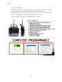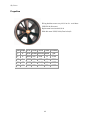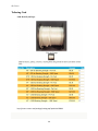
1
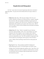
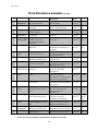
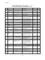
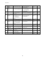
Sky Vision
HARDING UNIVERSITY
System Design and Project Plan
Sky Vision
Phil Varney
Cristina Belew
Julianne Pettey
Peng Yang
10/12/2010
1
Sky Vision
Table of Contents
Background……………………………………………………………………………………………….. 3
System Overview…………………………………………………………………………………………. 4
System Design ……………………………………………………………………………………………. 6
Block Diagram……………………………………………………………………………………. 7
Functional Description of Blocks……………………………………………………………….... 8
Project Plan ……………………………………………………………………………………………...11
Organization and Management…………………………………………………………………...12
Work Breakdown Schedule
Fall 2010…………………………………………………………………………………14
Spring 2011………………………………………………………………………………15
Gantt Chart
Fall 2010…………………………………………………………………………………17
Spring 2011………………………………………………………………………………18
Network Diagram
Fall 2010…………………………………………………………………………………19
Spring 2011………………………………………………………………………………20
Budget…………………………………………………………………………………………….21
Appendices
Appendix A: Requirements Specification………………………………………………………..22
Appendix B: FAA Regulations…………………………………………………………………...26
Appendix C: Budget References………………………………………………………………….30
2
Sky Vision
Background
The goal of Sky Vision is to design and construct a cost effective, mobile flight platform
with the capability to remotely capture video and transmit the data to a user on the ground in real
time. The need for aerial imaging spans a wide array of markets, such as search and rescue, law
enforcement, construction, the media, fire fighting, and general recreation.
Aerial imaging greatly expands the capabilities of the aforementioned markets. It
reduces the manpower (and thus costs and risks) needed for many dynamic situations, such as
monitoring the scene of a crime or surveying the extent of a wildfire. In short, aerial imaging
extends the sensing capabilities of a market from a two dimensional field into a third dimension:
the sky.
Currently, this capability is far too often accomplished through the use of expensive
rotary and fixed wing aircraft. The costs of the prior options often far eclipse the resources of
many markets, thus necessitating a cost effective alternative. The goal of Sky Vision is therefore
to create an aerial imaging product which meets both the high performance and low cost
requirements of many under financed markets.
Sky Vision will meet the above stated needs by being far less expensive than the current
methods used to obtain aerial images. As an alternative to renting or purchasing expensive
equipment outright, Sky Vision customers will be able to purchase one of our aerial surveillance
systems. Using Sky Vision will be much more convenient for the customer, since the system can
be easily transported to the required location. Sky Vision will use a lifting gas such as helium to
fly a small video camera to the altitude necessary to obtain the desired live video feed. The
camera will transmit the live video feed to a user interface on the ground. The system will be
able to be maneuvered and rotated by a lightweight propulsion system. This propulsion system
will be remote-controlled from the user interface on the ground.
3
Sky Vision
System Overview
The goal of Sky Vision is to provide a cost effective method of aerial surveillance for
dynamic situations. Sky Vision will consist of a lighter-than-air aerial platform with stable live
video imaging and a limited propulsion system. Since most markets with a need for aerial
surveillance also demand high adaptability, Sky Vision will measure no more than 1.30 m x 1.04
m x 0.56 m. To satisfy the needs of the customer, Sky Vision will be capable of both 360° of
azimuth rotation and 90° of elevation rotation. Azimuth rotation is defined as a horizontal
rotation in a fixed reference plane; in this case the fixed reference plane is the plane
perpendicular to an axis fixed to the device which passes vertically through the center of gravity
of the device when it is in a vertical orientation. Ninety degrees of elevation rotation is defined as
a rotation from the previously mentioned fixed plane to a position perpendicular to the plane,
directed downward. The propulsion system will provide lateral translation and also rotation to
position and orient the azimuth angle of the imaging system. The elevation rotation will be
provided independent of the propulsion/orientation system.
Sky Vision will be operated by the customer using a portable user interface device. The
user interface will provide four important functions: control of the imaging system and viewing
of the live video feed, control of the propulsion system (rotation and translation), and control of
deflation of the balloon in case of separation from the tethering system (as required FAA
regulation 101 subpart B, see Appendix B).
To use Sky Vision, the user will remove the system from storage and ensure the aerial
platform is correctly secured to the tethering system (prior to inflation with helium gas). The
platform will then be connected to the power source and both the platform and user interface will
be powered on. The user will then add the required volume of helium gas to inflate the platform
(note that the customer will provide any required helium gas, except for that required by system
development and testing). The tethering system will then be slowly released, allowing Sky
Vision to slowly rise to the desired altitude. Once Sky Vision has reached the desired altitude, the
user may then utilize the imaging and propulsion systems to obtain the desired field of view for
the live video feed. Once imaging is complete, the user will slowly reel in the device, while
4
Sky Vision
visually inspecting the tether for damage. Once the platform has reached ground level, the user
will inspect it to ensure the integrity of the platform has not been compromised. The valve
system will then be used to remove the helium gas from the platform. Following helium gas
removal, the system will be powered off and returned to storage.
5
Sky Vision
S y st e m D e s i g n
6
B l o c k D i ag r am
Sky Vision
7
Sky Vision
F u n c t i o n a l D e s c r i pt i o n o f B l o c k s
Propulsion System:
The propulsion system will consist of two propulsion units (probably fans) mounted on a
rotating shaft. The shaft will be capable of 360° of azimuth rotation. The propulsion
units will be capable of providing both stability against wind and lateral translation of
balloon.
Input: User control signal from user interface via motor control circuit (see ‘User
Interface’ functional description for specifics on user input mechanism)
Output: Desired rotation (360° in five minutes, or 0.2 rpm) and translation of
balloon (maximum of 5 N thrust to stabilize against maximum wind speed)
Communication System:
The communication system will remotely control the propulsion system of the blimp. It
will transmit a signal from the user interface to a motor control circuit that determines the
direction and speed of movement. This signal will be transmitted wirelessly and will be
in compliance with all relevant FCC communication standards and regulations.
Input: Signal generated from remote-control device on user interface and
transmitted at radio frequency at 2.4 GHz.
Output: Signal to motor control circuit and camera control circuit which sends
power to the propulsion units and camera (40 – 100 W to propulsion units and 2 –
6 W to camera system)
Power System:
The power system provides the necessary power for the propulsion system, user interface,
and communication system. The power system consists of a battery, a voltage regulator,
and on/off switching system. The power system will provide power to the system for a
minimum of one hour, with
Input: Power from battery (30 to 100 W).
Output: Power to other systems (15 – 40 W to propulsion units and 2 – 6 W to
camera system)
8
Sky Vision
Tethering System:
The tethering system includes both a reel device to allow for ascending and descending of
the balloon and also a tethering cable which is capable of supporting the balloon. The
device should be deployable to and from its maximum height of 36.6 meters within ten
minutes. In order to ensure that the height of the device does not exceed 36.6 meters, the
tethering system will only be capable of letting out 36.6 meters of cable. The material
will have a factor of safety against rupture of at least 2.0
Inputs: Mechanical reeling force, 1 – 15 N force applied at a sufficient distance.
Outputs: Change in device elevation, from zero meters to the maximum height of
36.6 meters.
Camera System:
The camera system will consist of a small camera mounted onto the balloon. The camera
will be capable of 90° elevation rotation, accomplished independent from motion
provided by propulsion system. The live video feed will be transmitted to the ground and
made viewable on the user interface. The camera will be adjusted to focus at a distance
sufficient to accommodate the maximum flight height. The video frame rate will be a
constant value (yet to be determined) as predetermined by specific camera selection.
Inputs: Control signal from user interface. 9 volt power supply from battery.
Outputs: Live video feed displayed on the user interface. Up to 90° elevation
rotation.
Plat fo rm:
The platform consists of both a helium filled balloon and the required mounting
infrastructure. The helium filled balloon will provide enough lift to bring the system to
the desired elevation, and the required mounting infrastructure will support the imaging
and propulsion systems. The platform will also contain a subsystem to rapidly deflate the
device in case of tether separation, as dictated by FAA regulation 101 subpart B.
Input: Specified volume of helium gas required to lift system (helium gas can lift
approximately 1.1 kg/m3 at 20° C and 1 atm. Emergency signal from tether
separation sensor.
Output: Desired elevation of the system. Rapid deflation of device when
emergency tether signal is received; separation of device from tether is a worst
case scenario and would result in catastrophic failure of device (most likely
outcome: complete destruction of device.
9
Sky Vision
User Interfa ce:
The user interface consists of the controls necessary to control the propulsion system and
imaging system. The user will be able to use the user interface to rotate the system 360°
and rotate the camera 90°. The propulsion system controls allow for user control of
camera stability. The live video feed will be viewable on the user interface
Input: Desired manipulation of propulsion and imaging systems as dictated by
user via a system of buttons and/or joysticks in order to accomplish desired
imaging.
Output: Control signal sent to communication system at 0 to 5 V DC
10
Sky Vision
P r o j e c t Pl a n
11
Sky Vision
Organization and M anagement
Sky Vision’s team consists of two electrical engineering students and two mechanical
engineering students. The project tasks will be distributed between the project members as
follows:
o Philip Varney (Mech. Eng.) - Phil is the project manager of Sky Vision, and
primarily responsible for making sure the subsystem plans are completed, integrated,
and tested on time. Phil is also responsible for finalizing all required reports and
ensuring they are completed on time. Phil will also be responsible for the design and
implementation of the propulsion system and the camera rotation system. Phil will
work with Cristina to assist her with any difficulties that arise during the development
of her responsibilities.
o Julianne Pettey (Elec. Eng.) - Julianne is responsible for project financing;
specifically, ensuring the budget is under control. The purchasing of any system
components will be done through her to ensure the budget outline is followed.
Julianne will also be responsible for the design and implementation of the camera
system and communication system. She will be responsible for integrating all of the
electrical subsystems and ensuring they function properly with the mechanical
systems. Julianne will work with Peng to ensure his tasks are done properly and
efficiently.
o Peng Yeng (Elec. Eng.) - Peng is primarily responsible for designing and
implementing the power system. He will also design the user interface system,
including controls for both the imaging and propulsion systems. Peng will also work
with Julianne to make sure her tasks are completed on schedule and also to assist her
in any difficulties which arise during the design and implementation of the camera
and communication systems.
12
Sky Vision
o Cristina Belew (Mech. Eng.) - Cristina is responsible for the design and
implementation of the platform (balloon and mounting frame) and tethering systems.
She is also responsible for examining any relevant FAA regulations and dictating to
the entire team what is required to ensure FAA regulations are adhered to. Cristina
will collaborate with Peng on the mechanical aspect of the user interface design. She
will also assist Phil in any difficulties encountered during the design and
implementation of the propulsion and camera rotation systems.
13
Sky Vision
Work Breakdow n Schedule Fall 2010
ID
Activity
Description
F1.0
F 2.0
Project
Management
Documentation
F 3.0
Project Choice
F4.0
Requirements
Specification
System Design
& Project Plan
Ensure project is completed
correctly and on time
Ensure changes and progress
is recorded
Decide on which problem
solution to pursue
Complete set of all system
requirements
Report of semester goals and
deadlines, along with
functional descriptions of
subsystems
Complete design of
subsystems
F 5.0
F6.0
Device Design
F6.1
Platform
Design
Design of balloon and
mounting infrastructure
F6.2
Camera Design
F
6.2.1
Imaging Design
Design of imaging system
and camera rotation system
Design of camera system to
provide live video feed
F
6.2.2
Camera
Rotation Design
Design of system to rotate
camera 90°
F6.3
Propulsion
Design
Stabilize, rotate, and translate
device
F6.4
Power Design
Design power system to
power device
F6.5
Communication
Design
Design system to transmit
user inputs/outputs to/from
device
F6.6
Tether Design
Design system to secure
device and transmit power
F6.7
User Interface
Design
F7.0
System Design
and Analysis
Final Design
Design system to receive
inputs and display live video
feed
Ensure correct integration of
subsystems and order parts
The final design of system
and subsystems
F8.0
·
Deliverables/
Checkpoints
Description of team member
task completion
Engineering notebooks, A3
reports, and design reports
Problem specification report
Requirements specification
document
System Design and Project Plan
final report
Component selection and
performance specifications. of
subsystems
Type of balloon; performance
specifications of balloon; design
of mounting brackets
Camera selection; camera
rotation design
Camera selection and
performance specifications; data
transmitter and receiver
Motor and mounting system
selection; performance
specifications
Propulsion unit design and
selection; movement
specifications; mounting design;
performance specifications
Battery selection; power
distribution design; performance
specifications
Communication method
selected; control circuitry
design; performance
specifications
Selection of tethering cord;
reeling device design;
performance specifications
User interface control circuitry
designed; case/type of controls
designed; performance specs.
Final system design and
documentation of parts ordering
Final Design Report (includes
schematics and project model)
Please note that ‘performance specifications’ includes test results
14
Duration
(days)
Aug. 23rd
– Dec. 9th
Aug. 23rd
– Dec. 9th
Aug. 23rd
– Sept. 7th
Sept. 7th –
Sept 28th
Sept. 28th
– Oct. 12th
People
Oct. 12th –
Nov. 16th
Ph, P,
J, C
Oct. 12th –
Nov. 2nd
C (1),
Ph (2)
Oct. 12th –
Oct. 26th
Oct. 12th –
Oct. 26th
J, Ph
Oct. 12th –
Oct. 26th
Ph
Oct. 12th Oct. 26th
Ph (1),
C (2)
Nov. 2nd –
Nov. 16th
P (1), J
(2)
Oct. 26th –
Nov. 9th
J (1), P
(2)
Nov. 2nd –
Nov. 16th
Oct. 22nd
– Nov. 9th
C (1),
Ph (2),
P (1)
P (1), J
(2)
Nov. 9th –
Dec. 7th
Nov. 9th –
Dec. 9th
Ph, P,
J, C
Ph, P,
J, C
Ph
Ph, P,
J, C
Ph, P,
J, C
Ph, P,
J, C
Ph, P,
J, C
J
Sky Vision
Work Breakdow n Schedule Spring 2011
ID
Activity
Description
S 1.0
Project
Management
S 2.0
Documentation
S 3.0
Device Build
S 3.1
Platform Build
Ensure project is
completed correctly and on
time
Ensure changes and
progress is recorded
Complete builds of
subsystems
Connect mounting
infrastructure to balloon
S 3.2
Camera Build
Build imaging system and
camera rotation system
S
3.2.1
S
3.2.2
Imaging Build
Build camera system
Camera
Rotation Build
Build of camera rotation
system
S 3.3
Propulsion
Build
S 3.4
Power Build
Build of propulsion system
to stabilize, rotate, and
translate device
Build power system to
power device
S 3.5
Communication
Build
Build system to transmit
user inputs/outputs to/from
device
S 3.6
Tether Build
Build system to secure
device and transmit power
S 3.7
User Interface
Build
Build system to receive
inputs and display live
video feed
S 4.0
Device Testing
S 4.1
Platform
Testing
Complete testing of each
subsystem
Test the platform to ensure
it can support subsystems
S 4.2
Camera Testing
S
4.2.1
Imaging
Testing
Ensure camera can provide
live feed and rotate through
specified angle
Ensure the camera can
provide satisfactory video
feed
Deliverables/
Checkpoints
Description of team member
task completion
Duration
(days)
Jan. 18th –
May 5th
People
Engineering notebooks, A3
reports, design reports
All of subsystems connected as
specified by design
Mounting brackets for tether,
propulsion system, and imaging
system attached to balloon
Imaging and camera rotation
subsystems connected. Camera
control circuitry built for both
imaging and camera rotation
Receiver/transmitting circuitry
built and connected to camera
Camera mounted to elevation
rotation shaft and motor. Motor
connected to control circuitry
Propulsion units built,
assembled, and mounted to
platform frame
Power distribution system and
voltage regulating system built
and connected to battery
Remote control circuitry built
and ready to be mounted to user
interface and aerial portion of
platform
Reeling mechanism built and
connected to cable. Cable
attachment to balloon
mechanism built
Device to contain interface
control circuitry and display
screen built. Display screen
circuitry built and connected to
user interface
Test results of subsystems;
modification recommendations
Results of balloon lift and
stability tests; modification
recommendations
Results of camera imaging and
rotation tests; modification
recommendations
Results of imaging testing;
modification recommendations
Jan 18th –
May 5th
Jan. 18th –
Feb. 22nd
Jan. 18th –
Feb. 8th
Ph, P,
J, C
Ph, P,
J, C
C (1),
Ph (2)
Jan. 18th –
Feb. 1st
J, Ph
Jan. 18th –
Jan. 25th
Jan 25th –
Feb. 1st
J
Jan 18th –
Feb. 1st
Ph (1),
C (2)
Feb. 8th –
Feb. 22nd
P (1), J
(2)
Feb. 1st –
Feb. 15th
J (1), P
(2)
Feb. 8th –
Feb. 22nd
C (1),
Ph (2),
P (1)
Feb. 1st –
Feb. 15th
P (1), J
(2)
Feb. 1st –
Mar. 8th
Feb. 8th –
Feb. 22nd
Ph, P,
J, C
C (1),
Ph (2)
Feb. 1st –
Feb. 15th
J, Ph
Feb. 1st –
Feb. 15th
J
15
Ph
Ph
Sky Vision
S
4.2.2
Camera
Rotation
Testing
Propulsion
Testing
Ensure camera can rotate
specified elevation range
S 4.4
Power Testing
S 4.5
Communication
Testing
S 4.6
Tether Testing
S 4.7
User Interface
Testing
S 5.0
Project Status
Ensure power outputs can
provide power for all
subsystems
Ensure system can
communicate to device at
max. altitude and
receive/transmit user
signals
Ensure tether can support
system and transmit power
Ensure user interface can
transmit/receive signal
from/to communication
system
Statement of project status
S 6.0
S 8.0
System
Integration
System Testing
and
Modifications
User’s Manual
S 9.0
Final Report
S 4.3
S 7.0
Ensure propulsion provides
for rotation and translation
Integrate subsystems to
ensure correct functionality
Testing of total integrated
system and corresponding
modifications
Instructions to user on how
to operate system
Presentation of final device
and system capabilities
Actual range of rotation
specified; modification
recommendations
Actual thrust output and rotation
rate of mounting shaft
quantified; modification
recommendations
Actual power output quantified;
modification recommendations
Feb. 1st –
Feb. 15th
Ph
Feb. 1st –
Feb. 15th
P (1),
C (2)
Feb. 22nd –
Mar. 8th
P (1), J
(2)
Actual communication range
quantified; modification
recommendations
Feb. 15th –
Mar. 1st
J (1), P
(2)
Actual reeling force quantified;
modification recommendations
Test results, modification
recommendations
Feb. 22nd –
Mar. 8th
Feb 15th –
Mar. 1st
C (1),
Ph (2)
P (1), J
(2)
Project status report
Feb. 15th –
April 5th
Mar 1st –
Mar. 29th
Mar. 22nd –
April 12th
Ph, P,
J, C
Ph, P,
J, C
Ph, P,
J, C
April 19th –
May 3rd
April 12th –
May 3rd
Ph, P,
J, C
Ph, P,
J, C
Provides fully integrated
prototype to test
Complete system prototype
User’s manual report
Final report document
16
Fall 2010
G a n tt C h a rt
Sky Vision
17
Spring 2011
G a n tt C h a rt
Sky Vision
18
Network Diagram Fall 2010
Sky Vision
19
Network Diagram Spring 2011
Sky Vision
20
Sky Vision
B udg e t
Item
Propulsion System
2 Fans w/ motor
Model DFR6B
Mount
Third positioning
motor
Possible Vendor
Cost
Date Estimated
www.ductedfans.com
$80.00
Sept. 20th, 2010
www.onlinemetals.com
www.ductedfans.com
$10.00
$20.00
Oct. 4th, 2010
Camera System
Camera
Receiver
Transmitter
Battery for camera
www.boostervision.com
www.boostervision.com
www.boostervision.com
Wal-Mart
$69.99
Included
Included
$2.00
Sept. 8th, 2010
Sept. 8th, 2010
Sept. 8th, 2010
Oct. 4th, 2010
Main Power Supply
Tether cable
Misc. cord, etc
Main battery
Alternative battery
Amazon.com
TBA
Ebay.com
www.maxprod.com
$50.00
$25.00
$60.00
$20.00 -$40.00
Oct. 4th, 2010
Oct. 4th, 2010
Oct. 4th, 2010
Oct. 11th, 2010
TBA
$25.00
$25.00
Oct. 4th 2010
Oct. 11th, 2010
Tethering System
All components
Tethering cord
http://secure.cartsvr.net
Platform
Balloon
Helium gas
www.giantadvertisingballons.com $250.00
www.hicodallas.com
$100.00
Sept. 28th, 2010
Oct. 11th, 2010
Communication
System
RC control system
Control circuitry
www.hobbypartz.com
www.sparkfun.com
$44.95
$30.00
Oct. 3rd, 2010
Oct. 11th 2010
www.onlinemetals.com
www.eplastics.com
TBA
$13.00
$20.00
$15.00
Oct. 11th, 2010
Oct. 11th, 2010
Oct. 11th, 2010
User Interface
Display screen
Materials
Control circuitry
Misc/Contingency
Total Estimated Cost
$202 - $182
$1000
21
Sky Vision
Appendix A:
Requirements Specification
Overview
The goal of Sky Vision is to design and construct a cost effective, mobile flight platform
with the capability to remotely capture video and transmit the data to a user on the ground
in real time. The need for aerial imaging spans a wide array of markets, such as search
and rescue, law enforcement, construction, the media, fire fighting, and general
recreation.
Aerial imaging greatly expands the capabilities of the aforementioned markets. It
reduces the manpower (and thus costs and risks) needed for many dynamic situations,
such as monitoring the scene of a crime or surveying the extent of a wildfire. In short,
aerial imaging extends the sensing capabilities of a market from a two dimensional field
into a third dimension: the sky.
Currently, this capability is far too often accomplished through the use of expensive
rotary and fixed wing aircraft. The costs of the prior options often far eclipse the
resources of many markets, thus necessitating a cost effective alternative. The goal of
Sky Vision is therefore to create an aerial imaging product which meets both the high
performance and low cost requirements of many under financed markets.
Problem Statement
Obtaining aerial imaging of a dynamic situation can be both costly and complicated.
There is a need spanning a wide range of markets for an aerial device with the capability
of remotely capturing aerial images at a low cost. In order to fulfill the market
requirements, the device should have the capability to be easily transported to the area of
interest.
22
Sky Vision
Requirements
§
The power system should allow for a minimum of one hour flight time and also a
minimum of 30 minutes of live video, not necessarily continuous, from the camera
system.
§
The motion of the device and/or camera should allow for both 360° of azimuth
rotation and 90° of elevation rotation of the camera in order to provide a stabilized
image (Stabilized: no more than 25% displacement within a 0.5 s interval of a screen
centered, locked object)
§
The 360 degrees of azimuth rotation should be accomplished in a five minute time
interval
§
The camera system will be able to lock on (via either user control or automation) to
some object on the ground and remain fixed on that object until the user acquires a
new target object
§
The device will be able to rise to a maximum height of no less than 36.6 meters (120
ft) in order to ensure customer’s needs for aerial imaging are met
§
The device should obey all pertinent FAA regulations (FAA regulation 101, subparts
A and B; see Appendix A)
§
The communication range of the device should be at least 50 meters
§
The device should be able to withstand maximum winds of at least 5 m/s.
§
The device should be no more than 0.43 m3 (15 cu. ft) and the dimensions should not
exceed 1.30 m x 1.04 m x 0.56 m. when deflated, in order to fit into the trunk of a
standard mid-sized car (based on stats for 2011 Honda Accord)
§
The device development costs should cost no more than 1,000 USD.
Deliverables
§
Parts manual and corresponding budget
§
User manual
§
Detailed schematic and final report on device capabilities
§
System capability specifications
23
Sky Vision
§
Aerial surveillance device
§
User interface
§
Non-supplied parts:
-
Helium gas will be provided for development and testing purposes, but the
customer will be responsible for obtaining helium gas for later flight
-
A user provided laptop computer may be necessary to view the live video feed
User Manual
1. Remove device from storage and ensure the tether system is correctly connected to
the blimp
2. Connect the power system to the tethering system and power on the device and user
interface
3. Add necessary helium gas to the blimp until fully inflated
- User must supply helium gas
4. Slowly extend tethering line to allow blimp to rise to desired elevation
5. Obtain desired imaging using camera and blimp positioning systems, done via the
user interface
6. Slowly reel in tethering line until blimp has reached ground level
- Maintenance: ensure blimp is intact with no leaks
- Maintenance: when reeling in tethering line, check visually for damaged areas
7. Remove gas from blimp and disconnect tether system from power system
8. Place system in storage
Test Plans
§
§
§
The power system will be connected to the imaging and propulsion systems and
tested at a short vertical height for one hour to verify power needs (this includes 30
min. of video feed testing). The time duration will be tested using a commercial
stopwatch device.
To test image stability, one minute of continuous video will be recorded with the
camera locked onto a single object for the entire one minute duration. The one
minute video clip will then be broken into 0.5 second intervals and it will be verified
that the locked object did not drift more than 25% of the screen size during each
interval.
To test 360° of azimuth rotation and 90° of elevation rotation, the device will be
flown indoors and the 360° will be verified by the ability of the camera to capture a
full panoramic picture (or protractor in case of camera failure), and the 90° elevation
24
Sky Vision
§
§
§
§
§
§
rotation measured using a protractor. The 360° azimuth rotation will be timed using a
commercial stopwatch device to verify the 5 minute rotation duration.
The device will be flown outdoors to verify camera locking ability. An object on the
ground will be preselected and the camera should keep the object in the video feed for
a duration of five minutes.
To verify the maximum flight height of 36.6 meters, the device will be flown and the
amount of tethering cable measured using a measuring tape and related appropriately
(accounting for cable droop due to the weight of the cable) to the height of the device.
This will cause the measured tether cable to be greater than the maximum flight
height. The appropriate relation for cable droop will be provided following
appropriate testing and analysis.
The device will be flown in 5 m/s or greater winds to test flight stability. To verify
flight stability, the positioning and camera systems should still be capable of locking
onto an object on the ground and remaining locked onto that object for a duration of
five minutes with 5 m/s wind present.
To allow for wind variability, a two week testing period will be selected and the
device tested at different states of wind speed. The extended testing time allows for
adjustments to be made to the device, as well as to account for random wind speed
variation.
The communication system will be tested by carrying the deflated device (including
propulsion and camera system) a distance of 36.6 meters on the ground away from
the user interface and verifying that the user can still maintain required
communication with the device. The distance between the device and the user
interface should be straight and free from obstructions.
The dimensions of the deflated device will be measured to ensure that both the
volume and dimensions of the device do not exceed the specified dimension/volume
requirements. The dimensions will be measured using a standard measuring tape.
25
Sky Vision
Appendix B: FAA Regulations
Subpart A - General
101.1 Applicability.
(a) This part prescribes rules governing the operation in the United States, of the following:
(1) Except as provided for in 101.7, any balloon that is moored to the surface of the earth or an
object thereon and that has a diameter of more than 6 feet or a gas capacity of more than 115
cubic feet.
(2) Except as provided for in 101.7, any kite that weighs more than 5 pounds and is intended to
be flown at the end of a rope or cable.
(3) Any unmanned rocket except:
(i) Aerial firework displays; and,
(ii) Model rockets:
(a) Using not more than four ounces of propellant;
(b) Using a slow-burning propellant;
(c) Made of paper, wood, or breakable plastic, containing no substantial metal parts and
weighing not more than 16 ounces, including the propellant; and
(d) Operated in a manner that does not create a hazard to persons, property, or other aircraft.
(4) Except as provided for in 101.7, any unmanned free balloon that(i) Carries a payload package that weighs more than four pounds and has a weight/size ratio
of more than three ounces per square inch on any surface of the package, determined by dividing
the total weight in ounces of the payload package by the area in square inches of its smallest
surface;
(ii) Carries a payload package that weighs more than six pounds;
(iii) Carries a payload, of two or more packages, that weighs more than 12 pounds; or
(iv) Uses a rope or other device for suspension of the payload that requires an impact force of
more than 50 pounds to separate the suspended payload from the balloon.
26
Sky Vision
(b) For the purposes of this part, a gyroglider attached to a vehicle on the surface of the earth
is considered to be a kite.
[Doc. No. 1580, 28 FR 6721, June 29, 1963, as amended by Amdt. 101-1,
29 FR 46, Jan. 3, 1964; Amdt. 101-3, 35 FR 8213, May 26, 1970]
101.3 Waivers.
No person may conduct operations that require a deviation from this part except under a
certificate of waiver issued by the Administrator.
[Doc. No. 1580, 28 FR 6721, June 29, 1963]
101.5 Operations in prohibited or restricted areas.
No person may operate a moored balloon, kite, unmanned rocket, or unmanned free balloon in a
prohibited or restricted area unless he has permission from the using or controlling agency, as
appropriate.
[Amdt. 101-1, 29 FR 46, Jan. 3, 1964]
101.7 Hazardous operations.
(a) No person may operate any moored balloon, kite, unmanned rocket, or unmanned free
balloon in a manner that creates a hazard to other persons, or their property.
(b) No person operating any moored balloon, kite, unmanned rocket, or unmanned free balloon
may allow an object to be dropped there from, if such action creates a hazard to other persons or
their property.
(Sec. 6(c), Department of Transportation Act (49 U.S.C. 1655(c)))
[Doc. No. 12800, Amdt. 101-4, 39 FR 22252, June 21, 1974]
Subpart B - Moored Balloons and Kites
Source: Docket No. 1580, 28 FR 6722 June 29, 1963, unless otherwise noted.
101.11 Applicability.
This subpart applies to the operation of moored balloons and kites. However, a person operating
a moored balloon or kite within a restricted area must comply only with 101.19 and with
additional
limitations imposed by the using or controlling agency, as appropriate.
27
Sky Vision
101.13 Operating limitations.
(a) Except as provided in paragraph (b) of this section, no person may operate a moored
balloon or kite(1) Less than 500 feet from the base of any cloud;
(2) More than 500 feet above the surface of the earth;
(3) From an area where the ground visibility is less than three miles; or
(4) Within five miles of the boundary of any airport.
(b) Paragraph (a) of this section does not apply to the operation of a balloon or kite below the
top of any structure and within 250 feet of it, if that shielded operation does not obscure any
lighting on the structure.
101.15 Notice requirements.
No person may operate an unshielded moored balloon or kite more than 150 feet above the
surface of the earth unless, at least 24 hours before beginning the operation, he gives the
following information to
the FAA ATC facility that is nearest to the place of intended operation:
(a) The names and addresses of the owners and operators.
(b) The size of the balloon or the size and weight of the kite.
(c) The location of the operation.
(d) The height above the surface of the earth at which the balloon or kite is to be operated.
(e) The date, time, and duration of the operation.
101.17 Lighting and marking requirements.
(a) No person may operate a moored balloon or kite, between sunset and sunrise unless the
balloon or kite, and its mooring lines, are lighted so as to give a visual warning equal to that
required for obstructions to air navigation in the FAA publication "Obstruction Marking and
Lighting" .
(b) No person may operate a moored balloon or kite between sunrise and sunset unless its
mooring lines have colored pennants or streamers attached at not more than 50 foot intervals
beginning at 150 feet above the surface of the earth and visible for at least one mile.
(Sec. 6(c), Department of Transportation Act (49 U.S.C. 1655(c)))
28
Sky Vision
[Doc. No. 1580, 28 FR 6722, June 29, 1963, as amended by Amdt. 101-4,
39 FR 22252, June 21, 1974]
101.19 Rapid deflation device.
No person may operate a moored balloon unless it has a device that will automatically and
rapidly deflate the balloon if it escapes from its moorings. If the device does not function
properly, the operator shall immediately notify the nearest ATC facility of the location and time
of the escape and the estimated flight path of the balloon.
29
Sky Vision
Appendix C: Budget References
Balloon Prices
The following were used as references for different sizes and types of balloons. They were found
at http://www.customadvertisingballoons.com/. The size of the balloon will not be larger than
eight feet or 2.4 meters in diameter. From the below reference, it is clear that a blimp shaped
balloon exceeds budget allowances, thus necessitating the use of a spherical balloon.
Helium Gas Costs
These are prices found for helium gas at a location in the Dallas/Fort Worth Area. The monthly
rental option would be used because of testing (testing would span approximately a two week
period). The prices were found on http://www.hicodallas.com/helium.php. There is also a ten
dollar pick-up and delivery fee.
30
Sky Vision
M aterial References
Aluminum
Quote of prices for sheets of 2024 alloy aluminum. The prices were found on
http://www.onlinemetals.com/ . This material will potentially be used for the foundation of the
platform and user interface.
Plexiglass
This is an alternative material for the user interface and platform. It was found on
http://www.eplastics.com/.
31
Sky Vision
C amera
BoosterVision GearCam (BVGM-1)
Features: Small Size & Light Weight Low
Power Consumption Powered by 9 Volt Battery
2.4 GHz Wireless Mini Color Camera with
Audio from built in microphone.
Size: 20mm (W) 20mm (H) 20mm (D) About
3/4 of an inch…the size of a dime!
Comes with no tuning needed PLL receiver, 12
volt ac/dc supply for receiver and camera 9 volt
battery clip, and ac power pack for Mini
GearCam. Camera/transmitter weight is only
.5oz, 2.5oz with 9 volt battery. Field of view 60
degrees, CMOS 380 TV lines of resolution
sensor.
Range 300-700 feet in the air on an aircraft, 300-500 feet on the ground. Over 1 mile with
the 14db patch antenna.
Receiver unit has SMA antenna connector with rubber duck antenna. Use optional HiGain receiver antenna available for additional range.
Consumer use item, no license needed. FCC certified.
List Price:
Our Price: $69.95
You Save: $5.00 (7%)
Radio C ontr oller for C omm unication System
Highlights
6 Channel 2.4GHz R/C Transmitter Complete Set w/ Receiver. Features complete
Forward/Backward, Left/Right, Up/Down & Pitch Control (RUDDER, AILERON,
ELEVATOR, Pitch AND THROTTLE)
New longer 3K battery mounting plate connects to main frame. It makes the center
of gravity closed to rotor blade, and can adjust the center of gravity according to the
weight of battery, it reduces the correction when the heli-rolling.
Rotor head for precision and smooth movements.
Great stable and sensitive mixing lever design! Can display the great stability and
32
Sky Vision
precision for 3D flight.
Using Ball and Hiller two systems mixing control. Through simple structure of Ball
control system, power-saving of Hiller system and CCPM control, can
simultaneously control 3 servo for AILE, EVLE, PIT 3 actions. This control system
is great for 3D flying control and extending life cycle of servos.
Software for Radio available for download from the website.
33
Sky Vision
B a tte r y
Option 1: Power supply on balloon
The following lithium polymer batteries were found at http://www.maxxprod.com/mpi/mpi701.html. The lithium polymer batteries could be a suitable alternative to other battery types, such
as lead acid or lithium ion.
Option 2: Power through tether (not feasible at this point)
UB1270 12V 7Ah Wheelchair Medical Mobility SLA Battery (12 V, 7 AH)
Price: $12.95 (http://cgi.ebay.com/UB1270-12V-7Ah-Wheelchair-Medical-Mobility-SLABattery-/120605337758?pt=US_Batteries&hash=item1c14a3689e)
Cost of cable: $23.00 for 100’ (need 120’: $50.00)
34
Sky Vision
Propulsion
“Using brushless motor can yield 16 to 40 + oz of thrust.
USD $28.00 (No motor)
Replacement rotor #wattr01 $9.99
With 400 motor USD $39.80 (Chart below)”
Volts Amps RPM Thrust Thrust Power Efficiency
V
A
RPM Grams Ounces Watts
9
8
19000
225
8.04
72
3.125
10
9
20700
265
9.29
90
2.944
11
10
22100
300
10.58
110
2.727
12
11
24500
360
12.62
132
2.727
35
g/w
Sky Vision
Tethering C ord
Solid Braid Nylon Rope
http://secure.cartsvr.net/catalogs/catalog.asp?prodid=1976902
36
Sky Vision
Contr ol Circ uitry
H-Bridge Motor Driver 1A
sku: COM-00315
Description: Faster, cheaper, smaller, better, right? The SN754410 Quad Half H-Bridge is just
that. Capable of driving high voltage motors using TTL 5V logic levels, the SN754410 can drive
4.5V up to 36V at 1A continuous output current! Please see datasheet for more information. This
is a pin to pin compatible replacement for the L293D.
Datasheets: SN754410
Pricing
$2.35
$2.12
$1.88
price
10-99 (10% off)
100+ (20% off)
This is a good IC for robotics. It is a quadruple half-H driver but by
connecting certain pins it can be used as a dual full H-bridge. See data sheet for
more info.
www.sparkfun.com
37