1
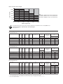
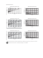
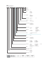
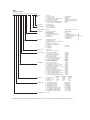
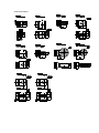
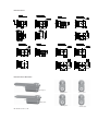
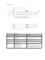
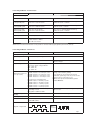
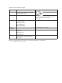
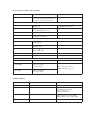
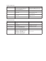
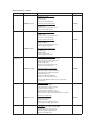
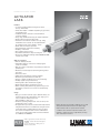
P R O D U C T D ATA S H E E T
ACTUATOR
LA36
Features:
• 12, 24 or 36 V DC Permanent magnetic motor
(IC only 12/24 V DC)
• Thrust from 500 N - 10.000 N depending on gear ratio
and spindle pitch
• 10.000 N actuator cannot be ordered without
hout
electrical endstop
• Heavy duty aluminium housing for harsh conditions
• Highly efficient acme thread spindle
• Protection class: IP66 for outdoor use (dynamic),
ynamic),
furthermore the actuator can be washed down
by a high pressure cleaner (IP69K – static))
• Hand crank for manual operation
• Integrated brake, high self-lock ability
• Endplay – 2 mm max.
• Non rotating piston rod eye
ees
• Back fixture turnable in steps of 30 degrees
S/EN ISO 8746
• Noise level: 73dB (A) measuring method DS/EN
actuator not locked
Options in general:
• Built in endstop switches
• Adjustable magnetic sensors for endstop signals
(code no. 1017031)
• Max. speed up to 160 mm/sec. depending on load and
spindle pitch
• Mechanical overload protection through integrated
slip clutch
• Hall effect sensor
• iFLEX options including IC, Parallel and BUS
• Mechanical potentiometer (not with IC)
• Analog or digital feedback for precise positioning
• Endstop signals (not potential free)
• Exchangeable cables in different lengths
• Different back fixtures and piston rod eyes
• When ordering AISI (304 and up) piston rod eye and
back fixture, stainless steel screws are automatically
included
Usage:
• Duty cycle at max. load 20% (up to 600 mm stroke, for
strokes between 601- 999 mm the max. duty cycle is
15%) at ambient temperature 25°C.
N.B. 10.000N 5% duty cycle.
• Ambient operating temperature -30°C to +65°C, full
performance from 5 - 40°C
• For applications operated at constant low temperatures
it might be beneficial to recommend a stronger version
of the LA36. This recommendation is done to reduce
the current consumption that in some combinations
can be up to 3 times higher than at normal conditions.
See TRD4187 and TRD4262
iFLEX is a descriptive term under which every
TECHLINE® actuator with built-in intelligence
is unified.
For more information on iFLEX, please see:
www.linak.com/techline
LA36 is ideal for use in harsh conditions. It is a solid
and powerful actuator based on the philosophy
that it must be able to operate under extreme
conditions. The actuator is ideal for mobile “offhighway” equipment such as agricultural, forestry
and construction machines.
LA36 Load versus Stroke Length
10000
Load - Push (N)
6800
4500
N.B.
LA36 500 - 1.700 N is with 20 mm spindle pitch
LA36 500 - 6.800 N is with 12 mm spindle pitch
LA36 500 - 10.000 N is with 8 mm spindle pitch
2600
1700
500
0
200
400
600
800
1000
Stroke Length (mm)
• For applications that only operate in pull the limitations are 999 mm stroke and 10,000 N load.
• The Piston Rod Eye is only allowed to turn 0-90 degrees
• Safety factor 2
Technical specifications
LA36 with 12V motor
Order number
Push
max.
(N)
Pull
max.
(N)
*Self-lock
min. (N)
Push
*Self-lock
min. (N)
Pull
Pitch
(mm/spindle rev.)
Typical speed
(mm/s)
Load
Standard stroke
lengths (mm)
In steps of
50 mm
Typical amp.
(A)
12 V
No
Full
36080xxxxxxAxxxxHxxxxxxxxxxx
10000
10000
13000
13000
8
11
7
100 - 999*
4.5
22
36120xxxxxxAxxxxFxxxxxxxxxxx
2600
2600
3400
3400
12
40.7
30.6
100 - 999
4.5
21
36120xxxxxxAxxxxGxxxxxxxxxxx
4500
4500
5800
5800
12
23.1
17.8
100 - 999*
4.5
20.7
36120xxxxxxAxxxxHxxxxxxxxxxx
6800
6800
8800
8800
12
15.5
11.9
100 - 999*
4.5
21
36200xxxxxxAxxxxFxxxxxxxxxxx
1700
1700
2200
2200
20
68
52
100 - 999
4.5
22
36200xxxxxxAxxxxExxxxxxxxxxx
500**
500**
1000
1000
20
160
135
100 - 999
4.5
20
Order number
Push
max.
(N)
Pull
max.
(N)
*Self-lock
min. (N)
Push
*Self-lock
min. (N)
Pull
Pitch
(mm/spindle rev.)
No
Full
No load
Full load
36080xxxxxxBxxxxHxxxxxxxxxxx
10000
10000
13000
13000
8
11
7
100 - 999*
2.4
10.4
36120xxxxxxBxxxxFxxxxxxxxxxx
2600
2600
3400
3400
12
41
32.3
100 - 999
2.4
10.4
36120xxxxxxBxxxxGxxxxxxxxxxx
4500
4500
5800
5800
12
23.3
18.9
100 - 999*
2.4
10.2
36120xxxxxxBxxxxHxxxxxxxxxxx
6800
6800
8800
8800
12
15.7
12.7
100 - 999*
2.4
10.3
No load
Full load
LA36 with 24V motor
Typical speed
(mm/s)
Load
Standard stroke
lengths (mm)
In steps of
50 mm
Typical amp.
(A)
24 V
36200xxxxxxBxxxxFxxxxxxxxxxx
1700
1700
2200
2200
20
68
52
100 - 999
2.4
10.3
36200xxxxxxBxxxxExxxxxxxxxxx
500**
500**
1000
1000
20
160
135
100 - 999
2.4
10.0
Order number
Push
max.
(N)
Pull
max.
(N)
*Self-lock
min. (N)
Push
*Self-lock
min. (N)
Pull
Pitch
(mm/spindle rev.)
36080xxxxxxCxxxxHxxxxxxxxxxx
10000
10000
13000
13000
8
36120xxxxxxCxxxxFxxxxxxxxxxx
2600
2600
3400
3400
12
41
33.5
100 - 999
2.0
8.0
36120xxxxxxCxxxxGxxxxxxxxxxx
4500
4500
5800
5800
12
23.3
19.1
100 - 999*
2.0
8.0
36120xxxxxxCxxxxHxxxxxxxxxxx
6800
6800
8800
8800
12
15.7
12.8
100 - 999*
2.0
8.0
36200xxxxxxCxxxxFxxxxxxxxxxx
1700
1700
2200
2200
20
68
52
100 - 999
2.0
8.0
36200xxxxxxCxxxxExxxxxxxxxxx
500**
500**
1000
1000
20
160
135
100 - 999
2.0
8.0
LA36 with 36V motor
Typical speed
(mm/s)
Load
No
Full
11
7
* There are limitations on the stroke length if you need full load, please see “ LA36 Load v. Stroke Length”
** Note: Fully loaded actuators need a softstart in order to prevent the clutch from slipping when starting (see curves).
** Note: Or available with iFLEX.
Standard stroke
lengths (mm)
In steps of
50 mm
100 - 999*
Typical amp.
(A)
36 V
No load
Full load
2.0
8.0
Speed and current curves:
LA36 12V motor speed vs. load
LA36 12V motor current vs. load
25
20mm/
20mm/ F gear 12mm/
F gear
E gear
160
140
Speed (mm/s)
Ampere
20
180
8mm/
H gear
12mm/
H gear
12mm/
G gear
15
10
5
0
0
2000
4000
6000
8000
10000
20mm/
E gear
120
100
80
20mm/
F gear
12mm/
F gear
60
40
20
12000
12mm/
G gear
12mm/
H gear
8mm/
H gear
0
Load (N)
0
2000
4000
6000
8000
10000
12000
Load (N)
LA36 24V motor speed vs. load
LA36 24V motor current vs. load
12
20mm
E gear
20mm/
F gear
12mm/
F gear
12mm/
G gear
180
8mm/
H gear
12mm/
H gear
160
10
Speed (mm/s)
140
Ampere
8
6
4
20mm/
E gear
120
100
80
20mm/
F gear
60
12mm/
F gear
40
20
2
12mm/
G gear
12mm/
H gear
8mm/
H gear
0
0
0
0
2000
4000
6000
8000
2000
4000
10000
6000
8000
10000
12000
Load (N)
Load (N)
LA36 36V motor speed vs. load
LA36 36V motor current vs. load
10
180
20mm/
E gear
20mm/
F gear
12mm/
F gear
12mm/
G gear
8mm/
H gear
12mm/
H gear
160
140
Speed (mm/s)
Ampere
8
6
4
2
20mm/
E gear
120
100
80
20mm/
F gear
60
12mm/
F gear 12mm/
G gear
40
20
12mm/
H gear
8mm/
H gear
0
0
0
0
2000
4000
6000
8000
2000
10000
4000
6000
8000
10000
Load (N)
Load (N)
All measurements above describe the spindle pitch (e.g. 20mm) and the gear type (e.g. E gear) of the actuator.
Speed and current are based on a nominal power supply of 12, 24, 36VDC.
12000
LA36
Ordering example Econ:
3 6 0 0 1
0 0 0 A P 0 0
0
0
-
1
0
1
0
0
0 2 8 8
2
1
S
0
0
0
Not used
Not used
Safety factor:
0=2
Cable:
0 = None
S = Straight
Y = Y-Cable
X = Special
Plug Type:
H = AMP
J = Deutsch (DT)
C = Flying leads
X = Special
Fire Category:
0 = None /HB
1 = V0
Install. Dim.:
XXXX = mm
Brake:
3 = Brake (push/pull)
2 = V2
Option Position: E = Gear ratio 1:7
F = Gear ratio 1:18
G = Gear ratio 1:31
H = Gear ratio 1:46
Piston Rod Eye:
1 = With slot
2 = Solid
4 = Outer thread
5 = Inner thread
6 = Ball eye
X = Special
1 = 0 degrees
2 = 90 degrees
4 = Outer thread
5 = Inner thread
6 = Rotated (interval 30° )
X = Special
Back fixture:
Colour:
1 = Dark Olivish Grey NCS S7000-N
X = Special
IP:
A = IP66
Motor Type:
A = 12VDC normal
B = 24VDC Normal
C = 36VDC Normal
* Interface:
00 = None
01 = Analogue
02 = OpenBus
03 = PLC
04 = MODBUS
06 = LINBUS
07 = IC Basic
08 = IC Advanced
09 = IC Parallel
XX = Special
Positioning:
0 = None
P = Potmeter
H = Hall
B = Analogue 0-10V
C = Analogue 0.5-4.5V
E = PWM 10-90%
F = PWM 20-80%
D = MODBUS
K = Single Hall
N = Analog 4-20 mA
Safety :
A = Safety nut
*
Stroke Length:
XXX = mm
Spindle Pitch:
080 = 8 mm
120 = 12 mm
160 = 16 mm
200 = 20 mm
Actuator Type:
36 = LA36
X = Special
LA36
Ordering example:
36 0
0
0 0
+ 0 0 0 0 0
0
0
0
Cable:
0 = No cable
1 = 1,5 m power cable
2 = 5 m power cable
3 = 0,2 m power cable with AMP connector
4 = 1,5 m power and 1,5 signal
5 = 5 m power and 5 m signal
6 = 1,5 m Y-cable, power and signal in one
7 = 5 m power Cable + Data cable M12x1
(0367046-1500)
(0367046-5000)
(0367006)
(0367046-1500+0367049-1500)
(0367046-5000+0367049-5000)
(0367020)
(Bus)
IP-degree:
2 = Standard (IP66)
Motor type:
A = 12 V DC with clutch
B = 24 V DC with clutch
C = 36 V DC with clutch
Stroke length:
XXX = mm
Acme spindle: 100, 150....999 mm
Feedback:
0 = Standard (No feedback)
Standard feedback
B = Analogue feedback 0 - 10V
C = Analogue feedback 0.5 - 4.5V
H = Dual Hall
P = Potentiometer
IFLEX feedback
D = Bus
1 = Single Hall
2 = Analogue feedback 0 - 10V
3 = Analogue feedback 0.5 - 4.5V
4 = Feedback 4-20mA
5 = PWM 10-90%
6 = PWM 20-80%
End stop:
0 = Without limt switches
1 = With limt switches
2 = With limt switches and endstop signals
3 = CS36
4 = CS36 with endstop signals
5 = With potential free limt switches
7 = IC Basic
8 = IC Advanced
9 = IC Parallel
A = Modbus
B = Linbus
Safety nut:
+ = Standard
S = With safety nut - only in push
Piston rod eye:
0 = M20 X 1 female adapter
1 = ø 12,9 mm hole, for 1/2" pin
2 = ø 12,2 mm hole, for 12 mm pin
3 = M12 X 1,75 male adapter
4 = M16 X 1,5 male adapter
5 = ø 12,2 hole with slide (Like LA34)
A = ø 12,2 hole with slide AISI 304
B = ø 12,9 hole with slide AISI 304
C = ø 12 H7 Ledøje AISI 304
D = ø 16 H7 Ledøje AISI 304
0361016
0361018-B
0361109-B
0361224
0361135
0361138
0361260
0361275
0361350
0361351
Back fixture:
0 = M20 X 1 female adapter
1 = ø 12,9 mm hole, for 1/2" pin
2 = ø 12,9 mm hole turned 90°, for 1/2" pin
3 = ø 12,2 mm hole, for 12 mm pin
4 = ø 12,2 mm hole turned 90°, for 12 mm pin
5 = M12 X 1,75 male adapter
6 = M16 X 1,5 male adapter
7 = ø 12,2 hole with slide (Like LA34)
8 = ø 12,2 hole with slide ( LA34) turned 90°
A = ø 12,2 hole with slide AISI 304
B = ø 12,2 hole with slide AISI 304 turned 90°
C = ø 12,9 hole with slide AISI 304
D = ø 12,9 hole with slide AISI 304 turned 90°
0361128
0361129
0361129
0361119
0361119
0361126
0361247
0361140
0361140
0361261
0361261
0361276
0361276
Gearbox:
A = Gear ratio 1 : 18
B = Gear ratio 1 : 31
C = Gear ratio 1 : 46
F = Gear ratio 1 : 7
Spindle type:
1 = 1-threaded acme spindle
2 = 2-threaded acme spindle
3 = 3-threaded acme spindle
4 = 4-threaded acme spindle
5 = 5-threaded acme spindle
A = 2 + adjustable reed limit switches
C = 3 + adjustable reed limit switches
D = 4 + adjustable reed limit switches
E = 5 + adjustable reed limit switches
Actuator type:
36 = LA36
8 mm pitch
N.A.
N.A.
10.000 N
N.A.
12 mm pitch
2.600 N
4.500 N
6.800 N
N.A.
20 mm pitch
1.700 N
2.400 N
N.A.
500 N
(2.5 mm pitch)
(8 mm pitch)
(12 mm pitch)
(16 mm pitch)
(20 mm pitch)
(on outer tube)
(on outer tube)
(on outer tube)
(on outer tube)
When ordering standard stroke length with endstop 1, 2, 3 or 4 the stroke length will be up to 4 mm shorter.
Magnet
LA36 Piston Rod Eye
LA36 Back Fixture
LA36 Back Fixture Orientation
“0” Degrees
“30” Degrees
“60” Degrees
“120” Degrees
“150” Degrees
“90” Degrees
NB. All with tolerance of ±4°
LA36 built-in dimensions:
When STROKE <300 = Built-in dimension: 200+STROKE LENGTH
When STROKE >300 = Built-in dimension: 250+STROKE LENGTH
I/O specifications: Power supply - Motor.
Item
Specification
Comment
Input voltage
12 VDC, ± 20%
24 VDC, ± 10%
36 VDC, ± 10%
Cable dimension: 2 x 2.2 mm²
(2 x AWG14) for all different voltages.
Duty cycle
20% at max. load
Ambient temperature 25˚ C
Current consumption
2 - 23 Amp. depending on load and
voltage (see graphs)
Connection
To extend actuator:
Connect Brown to positive
Connect Blue to negative
Power supply
To retract actuator:
Connect Brown to negative
Connect Blue to positive
* For differentiated duty cycle see “Usage”
Actuator direction can be controlled with a
double-throw switch with the middle position
“off”.
Please note that for all iFLEX options the power
supply must NOT be switched between plus and
minus for extending or retracting the actuator.
Positioning feedback – Potentiometer.
Item
Specification
Comment
Potentiometer
Bourns 0-10 K ohm A 5%, 10-Turn
Type: 3540 Wirewound
Output range with
8 mm spindle pitch
0 K ohm = 0 mm stroke
10 K ohm = 333 mm stroke
The same for all LA36 8 mm models.e.g.
166.6 mm stroke = 5 Kohm.
Output range with
12 mm spindle pitch
0 K ohm = 0 mm stroke
10 K ohm = 500 mm stroke
The same for all LA36 12 mm models.e.g.
250 mm stroke = 5 Kohm.
Output range with
20 mm spindle pitch
0 K ohm = 0 mm stroke
10 K ohm = 833 mm stroke
The same for all LA36 20mm models.e.g.
416.5 mm stroke = 5 Kohm.
Linearity
± 0.25%
Output protection
1 Kohm protection resistor
Connection
Common - = Black
+10V exitation = White
0 = 10V out = Violet
Absolute positioning
+10V or other value
NOTE: Please note that Potentiometer is not possible on varients with fast gear (Spindle pitch 20 mm, H Gear).
Positioning feedback – Hall sensors
Item
Specification
Comment
Relative positioning
Signal description
Can be used for positioning.
Input Voltage
12 – 36 V DC
Output voltage
Always the same as input voltage
Note: max. output voltage 24V DC
12V : 11V ± 1V
24V : 23V ± 1V
36V : 35V ± 1V
Resolution
(Distance the piston rod
moves per count)
LA362C: Actuator =
LA363C: Actuator =
LA363B: Actuator =
LA363A: Actuator =
LA365A: Actuator =
Cable dimension: 6 x 0.5 mm² (6 x AWG20) for all
different voltages.
The Hall sensor signals are generated by the
turning of the actuator gearing.
0.1 mm per count
0.2 mm per count
0.3 mm per count
0.4 mm per count
0.7 mm per count
These signals can be fed into PLC. The PLC
quadrature signals (fig. 1 below) can be used to
register position of the piston rod.
Movement per single Hall pulse:
LA362C Actuator = 0.4 mm per pulse
LA363C Actuator = 0.7 mm per pulse
LA363B Actuator = 1.0 mm per pulse
LA363A Actuator = 1.7 mm per pulse
LA365A Actuator = 2.9 mm per pulse
N.B. For more precise measurements, please
contact LINAK A/S.
Frequency
Frequency is 14-26 Hz on XOR output
depending on load.
Every pulse is “ON” for 10 ms
Low frequency with a high load.Higher frequency
with no load.
Current consumption
(standby)
15 mA
When actuator is not running.
Switching capacity
Max. 12 mA
Max. 680n F
Connection
XOR Hall output = Purple
Signal GND = White
Input
Diagram of Single Hall:
XOR Output
Micro Processor
Fig. 1
I/O Specifications: Analogue feedback.
Item
Specification
Comment
Description
The actuator can be equipped with electronic
circuit that gives an analog feedback signal
when the actuator moves
Input voltage
12 - 36 V DC
Feedback circuit to be powered 1 second before
motor runs, and until 1 second after the motor has
stopped. Cable dimension 6 x 0,5 mm2
(6 x AWG20)
Output voltage
0 -10 V (Option B)
0V = Fully retracted
10V = Fully extended
+/- 0.2 V
0,5 - 4,5V (Option C)
0,5V = Fully retracted
4,5V = Fully extended
Current
consumption
Max. 40 mA
Also when actuator is not running
Connection
Supply: Brown
Supply : Blue
Signal power: White
Signal: Purple
Signal GND: Black
Use cable 0367003-XXXX
Combinations
The Absolute positioning must be combined
with limit switches. Can be combined with
endstop signal.
Note: It is recommendable to have the actuator to activate its limit switches on a regular basis.
Endstop signal: max 20 mA available.
I/O Specification: IC (Basic and Advanced)
Item
Specification
Description
Easy to use interface with integrated
power electronics (H-bridge) for direct IC
connection. Soft start of the actuator
Comment
Power supply
Input voltage
12VDC ± 20%
24VDC ± 10%
Current consumption
12V, 4-26A depending on load
24V, 2-13A depending on load
Duty cycle
20% at maximum load
Power connection
Connect Brown to positive
Connect Blue to negative
Cable dimension 2 x 2 mm2
(2 x AWG14) for all voltages
Input: Signals to the actuator
Outwards direction
Extends the actuator
FW - Red (Pin 2)
Inwards direction
Retracts the actuator
BW - Black (Pin 1)
On/off voltages
> 67% of VIN = ON
< 33% of VIN = OFF
Input current
> 10 mA
Current consumption (standby)
70 mA
When actuator is not running.
Signal GND
Minimising signal noise
To be used with all signal outputs
Actuator fully
extended (OUT)
Signal when endstop switch in extended
position is activated
IN = Yellow (Pin 5)
Source current max. 100 mA
Output: Signals from the actuator
Actuator fully
retracted (IN)
Signal when endstop switch in retracted
position is activated
OUT = Green (Pin 6)
Output voltage min. VIN - 1V
Feedback: IC (Basic)
Item
Specification
Comment
Feedback, Hall
Single Hall signal
XOR: See fig. 1, page 9
Feedback, Voltage
0 - 10V / 0.5 - 4.5V
Ripple max. 200mV
Transaction delay max. 20ms
Linear feedback 0.5%
Source current max. 1mA
Output voltage
Typical: Input voltage -1V
Example on 24V version:
Output voltage on IN = 23V (± 0.5V)
Output voltage on OUT = 23V (± 0.5V)
Connection
See User manual
Feedback: IC (Advanced).
Item
Specification
Comment
Feedback, PWM
Frequency: Up to 200 Hz ± 5Hz
Duty cycle: Any low/high combination
between 0 and 100 percent
Output voltage: (VIN - 1V) ± 1V
Open Drain source current max. 12 mA
Feedback, Hall
Single Hall signal
XOR: See fig. 1, page 9
Feedback, Voltage
Any low/high voltage combination between
0 and 10 volts
Ripple max. 200 mV
Transaction delay max. 20 ms
Linear feedback 0.5%
Feedback, Current
Any low/high current combination between
4 and 20 mA
Transaction delay max. 20 ms
Linear feedback 0.5%
Source
Connection
See user manual
I/O Specification: Parallel
Item
Specification
Comment
Description
The parallel drive option supports up to 8
actuators
Power supply
12 V DC ± 20%
24 V DC ± 10%
Cable dimension 2 x 2 mm2
(2 x AWG14) for all voltages
Current consumption
12 V, 4 - 26 A depending on load
24 V, 2 - 13 A depending on load
Consumption per actuator
Feedback
No feedback available during parallel drive
Power connections
Black (Pin 1):
Red (Pin 2):
White (Pin 3):
Purple (Pin 4):
Yellow (Pin 5):
Green (Pin 6):
Enable backward (Master)
Enable forward (Master)
Signal GND
Inter communication
Endstop signal out
Endstop signal in
Cable dimension 6 x 0.5 mm2 (6 x AWG20)
See user manual
Environmental test – Climatic
Test
Specification
Comment
TRD number
Cold test
EN60068-2-1 (Ab)
Storage at low temperature:
Temperature: -40°C
Duration: 72h
Not connected
Tested at room temperature.
TRD0509
EN60068-2-1 (Ad)
Operating at low temperature:
Temperature: -30°C
Duration: 2h
Actuator is not activated/connected
Tested at low temperature.
TRD0509
EN60068-2-2 (Bb)
Storage at high temperature:
Temperature: +90°C
Duration: 72h
Actuator is not activated/connected.
Tested at room temperature
TRD0510
Storage at high temperature:
Temperature: +70ºC
Duration: 1000h
Actuator is not activated/connected
Tested at high temperature.
TRD0507
Dry Heat
Change of
temperature
EN60068-2-2 (Bd)
Operating at high temperature:
Temperature: +60°C
Int. max. 17%
Duration:700h
Actuator is activated
Tested at high temperature.
EN60068-2-14 (Na)
Rapid change of temperature:
High temperature: +100°C in 60 minutes.
Low temperature: -30°C in 60 minutes.
Transition time:<10 seconds
Duration: 100 cycles
Actuator is not activated/connected.
Tested at room temperature.
TRD0501
EN60068-2-14 (Nb)
Controlled change of temperature:
Temperature change 5°C pr. minute
High temperature: +70°C in 60 minutes.
Low temperature: -30°C in 30 minutes.
130 minutes pr. Cycle.
Duration: 1.000 cycles (90days)
Actuator is not activated/connected.
TRD0508
Tested at 250, 500 and 1.000 cycles at low and high
temperatures.
Damp heat
EN60068-2-30 (Db)
EN60068-2-3 (Ca)
Salt mist.
EN60068-2-52 (Kb)
Damp heat, Cyclic:
Relative humidity: 93-98%
High temperature: +55°C in 12 hours
Low temperature: +25°C in 12 hours
Duration: 21cycles * 24hours
Actuator is not activated/connected
Tested within 1 hour after condensation,
That means after upper temperature has been reached.
Damp heat, Steady state:
Relative humidity: 93-95%
Temperature: +40 ±2°C
Duration: 56 days
Actuator is not activated/connected.
Tested within one hour after exposure.
Salt spray test:
Salt solution: 5% sodium chloride (NaCl)
4 spraying periods, each of 2 hours.
Humidity storage 7 days after each.
Actuator not activated/connected.
Exposure time: 500 hours
TRD0505
TRD0518
TRD0506
Degrees of
protection
EN60529 – IP66
DIN40050 – IP69K
IP6X - Dust:
Dust-tight, No ingress of dust.
Actuator is not activated.
TRD0514
IPX6 – Water:
Ingress of water in quantities causing harmful effects is not
allowed.
Duration: 100 litres pr. minute in 3 minutes
Actuator is not activated.
TRD0513
IPX6 –Connected actuator:
Actuator is driving out and in for 3 min.
100(l/min) jet of water is placed at the wiper ring for 3 (min).
TRD0513
IPX6 –Connected actuator and push 6800 (N)
Actuator is driving out and in for 3 min. and
Push 6800(N) at the end-pos.
100 (l/min.) jet of water is placed at the wiper ring for 3 min.
High pressure cleaner:
Water temperature: +80°C
Water pressure: 80 bar
Spray angle: 45°
Spray distance: 100mm
Duration: From any direction 10 seconds of spraying
followed by 10 seconds rest.
Actuator is not activated.
Ingress of water in quantities causing harmful effects is not
allowed.
Chemicals
TRD0513
TRD0512
DUNK test
The actuator has been warmed up to 115ºC for 20 hours.
After this it is cooled down in 20ºC saltwater.
Cooling time: 5 minutes
Opened for checking salt deposit and water.
TRD0515
BS7691 / 96hours
Diesel 100%
Hydraulic oil 100%
Ethylene Glucol 50%
Urea Nitrogen saturated solution
Liquid lime 10% (Super- Cal)
NPK Fertilizer (NPK 16-4-12) saturated
Tested for corrosion.
TRD0525
Environmental test - Mechanical
Test
Specification
Comment
TRD number
Free fall from all sides:
Height of fall: 0.4 meter onto steel.
Actuator not activated/connected.
TRD0511
EN60068-2-36 (Fdb)
Random vibration:
Short time test:6.29g RMS
Actuator is not connected
Long time test:
7.21g RMS
Actuator is not connected
Duration: 2 hours in each direction
TRD0502
EN 60068-2-6 (Fc)
Sinus vibration:
Frequency 5-25Hz: Amplitude = 3.3mm pp
Frequency 25-200Hz: Acceleration 4g
Number of directions: 3 (X-Z-Y)
Duration: 2 hours in each direction.
Actuator is not activated
TRD0517
Bump
EN60068-2-29 (Eb)
Bump test:
Level: 40g
Duration: 6 milliseconds
Number of bumps: 500 shocks in each of 6 directions.
Actuator is not connected.
TRD0503
Shock
EN60068-2-27 (Ea)
Shock test:
Level: 100g
Duration: 6 milliseconds
Number of bumps: 3 shocks in each of 6 directions.
Actuator is not connected.
TRD0504
Free fall
Vibration
Environmental test - Electrical
Test
Specification
Comment
TRD number
Power supply
ASAE EP455 (1990)
Operating voltages +10V - +16V
Over voltage +26(V) / 5min.
Reverse polarity –26(V) / 5min.
Short circuit to ground 16 (V) / 5 min.
Short circuit to supply 16(V) / 5 min.
TRD0522
HF-immunity
EN61000-6-2
Level: 30 V/m. at 26 MHz – 1000 mHz
80% 1 KHz
TRD0516
Emmision
EN61000-6-4
Level is inside limits for 12 V motor
TRD0516
Level: 500 VAC/25-100hz for 1 minute
TRD0516
Load dump test only accepted on motor power
connection.
TRD0521
Insulation test
Automotive
transients
ISO 7637
Manual hand crank
The manual hand crank can be used in the case of power failure.
The cover over the Allen Key socket must be unscrewed before the Allen Key can
be inserted and the Hand Crank operated.
Hand Crank Torque: Max.16 Nm (at maximum load)
Piston Rod movement per turn
Gear A = 10.5 mm
Gear B = 6.0 mm
Gear C = 4.0 mm
Gear F = 27 mm
6 mm Allen key
Note:
• The power supply has to be disconnected during manual operation.
• If the actuator is operated as a Hand crank, it must be operated by hand or carefully by machine, otherwise there
is a potential risk of overloading and hereby damaging the actuator. LA36 with CS or Modbus options only
operate by hand.
Copyright © LINAK 2013.12 MA M9-02-148-P . Chapter 5.12
• With stainless steel screws: 5 mm Allen Key
Terms of use
The user is responsible for determining the suitability of LINAK products for specific application.
LINAK takes great care in providing accurate and up-to-date information on its products.
However, due to continuous development in order to improve its products, LINAK products are
subject to frequent modifications and changes without prior notice. Therefore, LINAK cannot
guarantee the correct and actual status of said information on its products.
While LINAK uses its best efforts to fulfil orders, LINAK cannot, for the same reasons as
mentioned above, guarantee the availability of any particular product. Therefore, LINAK reserves
the right to discontinue the sale of any product displayed on its website or listed in its catalogues
or other written material drawn up by LINAK.
All sales are subject to the Standard Terms of Sale and Delivery for LINAK. For a copy hereof,
please contact LINAK.
FOR MOUNTING INSTRUCTIONS AND GUIDANCE IN USAGE, PLEASE SEE THE RELEVANT USER’S MANUALS