1
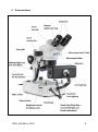
KERN & Sohn GmbH Ziegelei 1 D-72336 Balingen E-mail: [email protected] User instructions Jewellery microscope (stereo zoom) KERN OZG 493 Version 1.0 01/2015 OZG_493-BA-e-1510 Tel: +49-[0]7433- 9933-0 Fax: +49-[0]7433-9933-149 Internet: www.kern-sohn.com GB KERN OZG 493 Version 1.0 01/2015 User instructions Jewellery microscope (stereo zoom) Table of contents 1 Before use .................................................................................... 3 1.1 1.2 1.3 1.4 General notes ............................................................................................................................ 3 Notes on the electrical system ................................................................................................ 3 Storage ...................................................................................................................................... 4 Maintenance and cleaning ....................................................................................................... 5 2 Nomenclature ............................................................................... 6 3 Basic data ..................................................................................... 7 4 Assembly ...................................................................................... 8 5 Operation and functionality....................................................... 10 5.1 5.2 5.3 5.4 5.5 5.6 5.7 5.8 5.9 5.10 Getting started ........................................................................................................................ 10 Adjust the interpupillary distance ........................................................................................ 10 Adjusting the magnification .................................................................................................. 10 Dioptre adjustment and focussing ....................................................................................... 11 Adjusting the stand ................................................................................................................ 12 Using eye cups / High Eye Point eyepieces ........................................................................ 13 Lighting control ...................................................................................................................... 14 Using the dark field attachment and object clamp ............................................................. 15 Changing the bulb .................................................................................................................. 15 Changing the fuse .................................................................................................................. 15 6 Optical data ................................................................................ 16 7 Features ...................................................................................... 16 8 Trouble shooting ........................................................................ 17 9 Service ........................................................................................ 18 10 Disposal ...................................................................................... 18 11 Further information .................................................................... 18 OZG_493-BA-e-1510 2 1 Before use 1.1 General notes You must open the packaging carefully, to make sure that none of the accessories in the packaging fall on the floor and get broken. In general, microscopes should always be handled carefully because they are sensitive precision instruments. When using or transporting the microscope it is particularly important to avoid abrupt movements, as this may damage the optical components. You should also avoid getting dirt or finger prints on the lens surface, because in most cases this will reduce image clarity. To maintain the performance of the microscope, it must never be disassembled. So components such as lenses and other optical elements should be left as they were before use. Also the electrical parts in the base of the device must not be tampered with, as in this area there is an additional risk of triggering an electric shock. 1.2 Notes on the electrical system Before connecting to a mains power supply, you must make sure that you are using the correct input voltage. The information to select the correct power supply is located on the device, on the rear of the stand base. You must comply with this information. If you do not comply with these specifications, then fires or other damage to the device could occur. The main switch must also be switched off before the mains cable is connected. In this way you will avoid triggering an electric shock. If the original fuse should blow, it must only be replaced by an appropriate fuse. Suitable replacement fuses are included with the delivery. When carrying out any procedures whereby you come into contact with the electrical system of the device, such as, for example, changing the bulb or fuse, only carry out these procedures when the power is disconnected. Under no circumstances should you touch the integrated halogen bulbs or housings either during operation or directly after use. These bulbs produce significant heat and therefore there is a risk that the user could be severely burnt. So before handling the bulbs, you must check that they have cooled down. 3 OZG_493-e-1510 1.3 Storage You should ensure that the device is not exposed to direct sunlight, temperatures which are too high or too low, vibrations, dust or a high level of humidity. The ideal temperature range is between 0 and 40°C and a relative humidity of 85% should not be exceeded. The device should always be located on a rigid, smooth, horizontal surface. For devices with pillar stands, the microscope holder must not be rotated back too far. If you do this, there is a risk that the microscope could tip over. When the microscope is not being used, you should fit the objective cap and cover the microscope with the enclosed dust protective cover. If the eyepieces are being stored separately, the protective caps must be fitted to the tube connectors. In most cases, if dust and dirt gets inside the optical unit of a microscope this can cause irreversible errors or damage. The best way to store accessories which consist of optical elements, such as, for example, eyepieces and objectives, is in a dry box with desiccant. OZG_493-BA-e-1510 4 1.4 Maintenance and cleaning In any event, the device must be kept clean and dusted regularly. If any moisture should be occur, before you wipe down the device you must ensure that the mains power is switched off. When glass components become dirty, the best way to clean them is to wipe them gently with a lint-free cloth. To wipe oil stains or finger prints off the lens surface, moisten the lint free cloth with a mixture of ether and alcohol (70 / 30 ratio) and use this to clean the lens. You must be careful when handling ether and alcohol, as these are highly flammable substances. You must therefore keep it away from naked flames and electrical devices which can be switched on and off, and only use it in well-ventilated rooms. However organic solutions of this type should not be used to clean other components of the device. This could lead to damage to the paint finish. To do this, it is sufficient to use a neutral cleaning product. You could also use the following cleaning products to clean the optical components: Special cleaner for optical lenses Special optical cleaning cloths Bellows Brush When handled correctly and checked regularly, the microscope should give many years of efficient service. Should repairs still be necessary, please contact your KERN dealer or our Technical Department. 5 OZG_493-e-1510 2 Nomenclature OZG_493-BA-e-1510 6 3 Basic data Optical system Greenough Magnification ratio 5.1:1 Dimmable lighting Yes Tube angled at 45° Interpupillary distance 55 – 75 mm Dioptre adjustment On both sides Packaging dimensions WxDxH 365x292x470 mm Standard configuration Model Tube Eyepiece KERN OZG 493 7 Binocular HWF 10x Ø 21.5 mm Field of view Objective mm Zoom Ø 28 – 5.6 0.7x – 3.6x Stand Illumination Pillar 12V / 10W Halogen (reflected light) 12V / 10W Halogen (transmitted light) 10W fluorescent lighting (front light) OZG_493-e-1510 4 Assembly The first step is to position the microscope stand on a firm, level surface. The holder with the head is already on pillar of the stand, but you must always check whether it is fixed securely and that it is in the correct position (preferably centrally and facing to the front). When packed, the head is fitted to the holder ring and rotated at a position of 180°. For this reason it must then be rotated forwards (first undo the adjusting screw and afterwards tighten it up again), to ensure the most comfortable position for using the microscope. Please see section 5.5 for more details on adjusting the stand. Ideally, the holder and head are then parallel on the central axis of the stand base (see figure on page 9). Both eyepieces are already fitted in the tube. You just need to remove the protective film which covers them. When doing this make sure that you do not touch the optical lenses with your fingers. In general you should avoid using two eyepieces with different magnifications. When changing the eyepieces, you must also loosen the small silver screw under the eyepiece on the tube connectors and once the new eyepiece is fitted, then it must be re-tightened. The front light is fitted to the front of the stand base using the hinged arm delivered with the microscope. To do this there is a screw connection both on the stand as well as the bulb housing of the front light. After that you should bring the front light into the correct position. With regard to the use of transmitted light illumination you must make sure that the frosted glass stand inlayd is fitted in the centre of the stand base, so that the transmitted light can be used correctly. It is always best to fix the different stand inlays using the adjusting screw on the front side of the stand base. Additional optional attachments: The eye cups supplied with the microscopes can be fitted to the eyepieces. (see section 5.6) OZG_493-BA-e-1510 8 Assembled jewellery microscope (stereo zoom) 9 OZG_493-e-1510 5 Operation and functionality 5.1 Getting started After assembly, if the microscope is ready for use, then you must first establish a power connection using the cable which is connected to the device. Please see section 5.7 for more details on adjusting the lighting. Do not forget to remove the cap from the bottom of the objective, so that you will then be able to see a reflection of the object being observed in the eyepiece. All important functions which relate to the use of the devices in this document are described in the following sections. 5.2 Adjust the interpupillary distance Different users have different interpupillary distances. So each time a different person uses the microscope, the gap between the two eyepieces must be re-adjusted. While you are looking through the eyepieces, use one hand to hold the righthand or lefthand prism housing firmly. By rotating outwards or inwards, you can either increase or reduce the interpupillary distance. As soon as the lefthand and righthand visual fields exactly overlap each other, this is the correct interpupillary distance. 5.3 Adjusting the magnification As the KERN OZG 493 series covers stereo zoom microscopes, then you adjust the magnification using the two zoom adjustment wheels on the lefthand and righthand side of the microscope head. Chapter 6 “Optical data” gives information on the possible overall magnification which the microscope can produce. It will also include the optional use of different eyepieces. OZG_493-BA-e-1510 10 5.4 Dioptre adjustment and focussing A special feature of stereo microscopes is that they are fitted with an optical unit which has a relatively high depth of field. In order to be able get the most benefit from this feature, each user must synchronise the focussing mechanisms for themselves. The steps to do this are described in the following section. 1. Place the object to be observed on the working surface under the objective. 2. Put both dioptre adjustment rings into the starting position of 0. 3. Use the zoom control dials to set the smallest possible magnification. 4. Look through the right eyepiece with the right eye and bring the object into focus by using the focus control dials. 5. Now set the largest possible zoom factor. 6. Once again, still only looking through the right eyepiece, bring the object into focus 7. Then set the smallest possible zoom factor again. 8. If the object then does not appear to be in focus, adjust the focus on the dioptre adjustment ring of the right eyepiece. 9. In order to get the highest level of accuracy when adjusting the focus, you should repeat steps 5-8. 10. Afterwards set back to the smallest possible zoom factor. 11. Then look through the left eyepiece with the left eye and use the lefthand dioptre adjustment ring to also adjust the optimum focus of the object. 12. In this way, the object being observed will be in focus at any zoom setting. 11 OZG_493-e-1510 5.5 Adjusting the stand Torque of the focus wheels You can adjust the torque of the focus wheels by turning the ring which is fitted along the axis of the lefthand focus wheel. To do this you need a special wrench which is included with delivery. The ring has holes which the wrench can hook into, so that you can then turn it in the desired direction. Depending on the direction of the turn, the torque will be increased or decreased. On one hand, this function can help to make it easier to adjust the focus and on the other hand it can prevent the microscope head from slipping down unintentionally. In this way you can avoid possible damage which could occur if the objective lens and the object being observed should collide. Height adjustment Fixing the microscope holder With a stereo microscope on a pillar stand, the microscope head can be height adjusted using the focus wheels and in addition, the microscope holder can be fixed at any point on the pillar, depending on the application requirements. To primary way to fix the position is to use an adjusting screw (1) on the holder. There is a metal ring which also ensures sufficient grip and which is fixed with a second screw (2) under the holder on the pillar. This metal ring proves to be particularly useful when the screw (1) on the holder is loosened, to swing the microscope head to the side. OZG_493-BA-e-1510 12 5.6 Using eye cups / High Eye Point eyepieces The eye cups supplied with the microscope can basically be used at all times, as they screen out intrusive light, which is reflected from light sources from the environment onto the eyepiece, and the result is better image quality. But primarily, if eyepieces with a high eye point (particularly suitable for those who wear glasses) are used, then it may also be useful for users who don’t wear glasses, to fit the eye cups to the eyepieces. These special eyepieces are also called High Eye Point eyepieces. They can be identified by the glasses symbol on the side. They are also marked in the item description by an additional “H” (example: HSWF 10x Ø 23 mm). When fitting the eye cups, make sure that the dioptre setting is not moved. We would therefore advise that you hold the dioptre adjustment ring on an eyepiece with one hand while you fit the eye cup with the other. Before using the microscope, users who wear glasses must remove the eye cups, which you may find on High Eye Point eyepieces. As the eye cups are made of rubber, you must be aware that when you are using them, they can become slightly dirty through grease residues. In order to maintain hygiene, we would therefore recommend that you clean the eye cups regularly (e.g. with a damp cloth). Eye cups High Eye Point eyepiece (identified by the glasses symbol) 13 OZG_493-e-1510 5.7 Lighting control One of the mains switches fitted in the left rear corner of the stand basis ensures that the device will be supplied with power when the plug is connected to the mains. Control of the lighting unit is flexible and it can be adjusted to suit the application requirements using the control wheel in the right rear corner of the stand base. This control wheel has four positions: OFF position I position II position III position Reflected light and transmitted light are switched off Reflected light is switched on Reflected light and transmitted light are switched on Transmitted light is switched on You can control the light intensity of the lighting by turning the dimmer wheel on the lefthand side of the stand base in a particular direction. If reflected and transmitted light are switched on at the same time, then you cannot adjust the light intensity of each one separately. The front light must be treated separately to the reflected and transmitted light, due to the way it is controlled. Indeed it also only operates if the mains switch is switched on, but it also has its switch on its housing which can be used to switch it on and off. It is not connected to the dimmer wheel and does not have one of its own. So the light intensity does not vary at all. However, the advantage of the front light is that it can be adjusted to various positions because of its hinged arm bracket. OZG_493-BA-e-1510 14 5.8 Using the dark field attachment and object clamp A dark field attachment and an object clamp are essential accessories for examining jewellery and precious stones under a microscope. Assembly is very easy. Simply use the dark field attachment in place of the stand inlay and secure it with the adjusting screw. The object clamp can be fitted on one of the two metal pins which are screwed onto the front corner of the stand base surface. A shorter metal pin is also delivered with the clamp, and this can be used in place of the one that is there, if it is too long. You must adjust the clamp so that the top of the clamp, where the object to be observed will be fixed, is located centrally over the dark field attachment. 5.9 Changing the bulb Halogen Before changing the halogen bulb, you must always switch off the device and unplug it from the mains. You must also make sure that the bulb and housing have cooled down, so that you avoid any risk of possible burn injuries. In order to change the halogen bulb in the reflected light unit, you must remove the filter bracket which is screwed onto the housing (the filter is fitted loosely). After that, you can pull the bulb, which is connected to a spotlight unit, out of the socket. This means that you must replace the entire unit. Once the new bulb is fitted, you can screw the filter holder with correctly inserted filter back on to the lamp housing. To change the halogen bulb for a transmitted light unit, you must first remove the stand inlay (undo adjusting screws first) and (if used) the filter which is underneath. The bulb which appears under the opening can then be simply pulled out of its socket and replaced with a new bulb. You must then position and fix the filter and stand inlay correctly. Please always use cloth gloves or similar to hold and fit a new bulb otherwise grease and dust residue on the surface of the bulb could have a negative effect on its brightness and service life. 5.10 Changing the fuse There are two fuses on the rear of the microscope stand base (label: “Fuse”). If the fuse has blown, then with the device switched off and the power disconnected, the fuse can easily be unscrewed using a flat blade screw driver and replaced with a new one. 15 OZG_493-e-1510 6 Optical data 7 Features Model outfit Kern model Order number OZG 493 Eyepieces Dark field attachment Object clamp Stand inlay Stand WF 5x / Ø 16.2 mm WF 10x / Ø 21.5 mm WF 15x / Ø 15 mm WF 20x / Ø 10 mm ○○ ●● ○○ ○○ OZB-A4101 OZB-A4106 OZB-A4103 OZB-A4104 Dark field attachment ● OZB-A4601 Object clamp (steel wire) ● Frosted glass / Ø95 mm ● black-white / Ø95 mm ● Pillar, with 12V / 10W Halogen (transmitted light and reflected light) and 10W fluorescent lighting (front ● light) ● = Standard configuration OZG_493-BA-e-1510 OZB-A4604 OZB-A4805 OZB-A4806 ○ = Option 16 8 Trouble shooting Electrical system Problem Possible causes The lighting unit (if fitted) cannot be The power cable is either not connected or switched on not connected correctly The bulb is not fitted The bulb has blown The fuse has blown The brightness control is set to the lowest level The bulb has blown The wrong bulb has been used The input voltage was too high The bulb flickers The bulb is not correctly fitted The lamp is worn out The bulb brightness is not sufficient The wrong bulb has been used The input voltage is too low Optical unit Problem Possible causes You can see two images The interpupillary distance is not set correctly The magnifications of the eyepieces do not match There is dirt on the object being observed There is dirt in the visual field There is dirt on the eyepiece surface The image is unclear There is dirt on the objective surface The focus wheels are jammed The torque of the focus wheels is set too high The microscope head slips down The torque of the focus wheels is set too low while you are viewing the object Eyes get tired easily The dioptre adjustment is not correct The brightness adjustment is not correct 17 OZG_493-e-1510 9 Service If, after studying the user manual, you still have questions about commissioning or using the microscope, or if unforeseen problems should arise, please get in touch with your dealer. The device may only be opened by trained service engineers who have been authorised by KERN. 10 Disposal The packaging is made of environmentally-friendly materials, which you can dispose of at your local recycling centre. Disposal of the storage box and device must be carried out by the operator in accordance with all national or regional laws in force in the location of use. 11 Further information The illustrations may differ slightly from the product. The descriptions and illustrations in this user manual are subject to change without notice. Further developments on the device may lead to these changes. All language versions contain a non-binding translation. The original German document is the binding version. OZG_493-BA-e-1510 18