Transcript
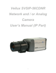
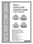
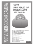
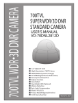
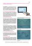
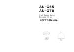
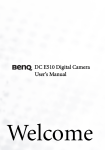
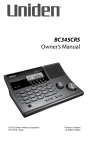
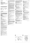
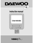
Precaution
IP NETWORK
DNR COLOR
CAMERA
USER’S MANUAL
1. Features
Contents
1. Features
Do not Keep the camera face to
strong light directly
The lightning flash with an arrowhead symbol, within an equilateral triangle is
intended to alert the user to the presence of uninsulated “dangerous voltage”
within the product's enclosure that may be of sufficient magnitude to
constitute a risk of electric shock to persons.
8
9
1/3" Sony Super HAD CCD
Multi-level user ID & password
Color 560 TV Lines : NTSC(410,000 pixels), PAL(470,000 pixels)
Encryption of user ID/password, video, audio, data
True Day & Night (ICR Type-IR Cut Filter Removable)
Remote configuration and status using web-based tool
DNR (Digital Noise Reduction) technology resulting in a clear and
sharp image display even in the dark
Firmware upgradable for future proof
Do not install the camera in
extreme temperature conditions.
Do not expose the camera to
rain or spill beverage on it.
Do not disassemble the camera
even if troubles happened
Do not install the camera under
unstable lighting conditions
Changes or modifications not expressly approved by the
manufacturer could void the user’s authority to operate the equipment.
To avoid malfunctions, never
use the camera close to a gas
or oil leak
To prevent electric shock and risk of fire hazards:
Do NOT use power sources other than that specified.
Do NOT expose this appliance to rain or moisture.
Do not install or use the camera
in an environment where the
humidity is high
4. Installation
11
5. Setup Menu Flow
14
6. How to Set up the Function
6-1. EXPOSURE
6-2. WHITE BAL
6-3. DAY/NIGHT
6-4. MOTION
6-5. PRIVACY
6-6. OPTION
6-7. DISPLAY
6-8. SYNC
6-9. INITIAL
6-10. EXIT
16
17
21
22
23
26
27
31
32
33
33
7. Specifications
34
IP NETWORK DNR COLOR CAMERA 3
⑤ Zoom Handle
Used to adjustzoom magnification by turning
⑥ OSD Menu
UP
DOWN
ENTER
Base
1/2” Bolt
1. Remove screws with Wrench provided in the box.
2. Disassemble the camera as shown above.
3. Install the base of camera on a desired location.
4. Adjust the position of the camera. If required,
readjust the Vari-focal Lens settings.
5. Closed the dome cover and seal the camera with the ring
Make sure screws are fastened tightly
BRIGHTNESS
Modem
DDNS Server
Laptop PC
LENS
BACKLIGHT
SHUTTER
Desktop PC
)
)
Dome Guide Ring
⑦ Service Video
)
)
)
Front Ring
)
)
AGC
CARRIER
)
)
PDA
Dome
SENS UP
)
RETURN
WB MODE
WHITE BAL
RED CONT
BLUE CONT
PUSH AUTO
RETURN
D/N MODE
DAY/NIGHT
Mobile Phone
Relay
Used to connect it with external viewer as follows.
8 IR LED
Router
INTERNET
O-Ring
Service Video
Sensor
AUTO LEVEL
FILTER DLY
L-Rench
IP NETWORK DNR COLOR CAMERA 11
12 IP NETWORK DNR COLOR CAMERA
IP NETWORK DNR COLOR CAMERA 13
6-2. WHITE BAL
EXPOSURE
LENS
BRIGHTNESS
BACKLIGHT
SHUTTER
AGC
SENSE UP
RETURN
EXPOSURE
LENS
BRIGHTNESS
BACKLIGHT
SHUTTER
AGC
+...
+...
ON
OFF
+...
+...
+...
SENSE UP
RETURN
+...
+...
+...
+...
LOW
MID
HIGH
AGC OFF
+...
DC
ELC
<0~60>
ON
OFF
1/60
FLC
<1/250~1/10000>
LOW
MID
HIGH
AGC OFF
OFF
<X2~X32>
Various softwares for PC, PDA and mobile phone
50 Concurrent Access
EXPOSURE
LENS
BRIGHTNESS
BACKLIGHT
SHUTTER
AGC
SENSE UP
RETURN
+...
+...
+...
1/60
FLC
<1/250~1/10000>
+...
+...
1. Press the ENTER button
-Main setup menu is displayed on the monitor screen.
MENU
EXPOSURE
WHITE BAL
DAY/NIGHT
MOTION
PRIVACY
OPTION
DISPLAY
SYNC
INITIAL
EXIT
6-1-6 SENS UP
You can always get the clear image with this function under
night or lowlighting level
-OFF, <X2~X32>
EXPOSURE
LENS
BRIGHTNESS
BACKLIGHT
SHUTTER
AGC
SENSE UP
-When LENS is DC, it is possible to select it. Another becomes
NOT USE. It becomes 1/60 at NTSC. It becomes 1/50 at PAL.
RETURN
+...
+...
+...
+...
+...
OFF
<X2~X32>
6-1-5 AGC
IP NETWORK DNR COLOR CAMERA 19
+...
+...
+...
+...
+...
+...
+...
INT
USE
2. Select a desired function by using the Up and Down buttons
-Place the cursor over a desired item
3. Set up a selected item by using the Left and Right buttons.
4. To finish the setting, ‘EXIT’ and press the ‘ENTER’ button.
6-2-1 WB MODE
Use the White Balance function to adjust the screen color.
20 IP NETWORK DNR COLOR CAMERA
Pre-alarm and Post-alarm video recording in the PIMA server in case of event
(motion and sensor triggering)
OPTION
TITLE
NEGA/POSI
1. If the OPTION menu screen is displayed, use the Up and
Down buttons so that the arrow indicates ‘TITLE’.
<--- ---> BS POS END
ABCDEFGHIJKLM
NOPQRSTUVWXYZ
abcdefghijklm
nopqrstuvwxyz
0123456789:;.
*/+-~!#%&()”_
SHARPNESS
MIRROR
ZOOM
PANTILT
RETURN
IP NETWORK DNR COLOR CAMERA 21
RED CONT
BLUE CONT
PUSH AUTO
ATW
AWC
MANUAL
6 IP NETWORK DNR COLOR CAMERA
DETECT MODE
DETECT AREA
SENSITIVITY
ALARM TIME
AREA
MASK
PRIVACY
LEVEL
TOP
DOWN
LEFT
RIGHT
TITLE
NEGA/POSI
SHARPNESS
MIRROR
OPTION
ZOOM
DISPLAY
AUTO
DAY
NIGHT
EXT
<0~18>
<4 SEC~10 SEC>
Select one of the following 3 modes, for your appropriate
purpose
-ATW, AWC, MANUAL
AUTO LEVEL
FILTER DLY
TITLE
MOTION DET
SYNC
INT
EXT
USE
NOT USE
INITIAL
OPTION
TITLE
NEGA/POSI
SHARPNESS
MIRROR
ZOOM
PANTILT
RETURN
1. If the OPTION menu screen is displayed, use the Up and
Down buttons so that the arrow indicates ‘NEGA/POSI’.
2. Set up a selected item by using the Left and Right buttons.
28 IP NETWORK DNR COLOR CAMERA
ZOOM
PANTILT
RETURN
6-6-4 MIRROR
You can display pictures in mirror.
NORMAL , MIRROR, VERTICAL, ROTATE can be selected.
MENU
EXPOSURE
WHITE BAL
DAY/NIGHT
MOTION
PRIVACY
OPTION
DISPLAY
SYNC
INITIAL
EXIT
2. Select a desired mode by using the Left and Right buttons according
to the picture display you want.
-AUTO, DAY, NIGHT, EXT
6-3-2 AUTO LEVEL
+...
+...
+...
+...
+...
+...
+...
INT
USE
2. Select a desired function by using the Up and Down buttons
-Place the cursor over a desired item
3. Set up a selected item by using the Left and Right buttons.
4. To finish the setting, ‘EXIT’ and press the ‘ENTER’ button.
When it is AUTO. 0 to 18 can be selected.(It changes by setting AGC)
-AGC OFF : NOT USE
-AGC LOW : 0 to 3 can be selected.
-AGC MID : 0 to 11 can be selected.
-AGC HIGH : 0 to 18 can be selected.
6-4. MOTION
Your camera transmits an alert signal when it detects
motion of an object on the screen. If you connect the
IP NETWORK DNR COLOR CAMERA
OPTION
TITLE
NEGA/POSI
SHARPNESS
MIRROR
ZOOM
PANTILT
RETURN
23
OPTION
TITLE
NEGA/POSI
SHARPNESS
MIRROR
ZOOM
PANTILT
RETURN
+...
POSI
NEGA
<0~15>
NORMAL
MIRROR
OFF
<ON1~ON8>
ON
OFF
6-6-6 PANTILT
This function can be used when setted ON in ZOOM function.
Please select the PANTILT ON and get out from Menu and operate
the PAN/TILT by pressing the buttons of UP,DOWN, RIGHT(R), LEFT(L)
on the Back Side of Camera.
1. Press the ENTER button
-Main setup menu is displayed on the monitor screen.
MENU
EXPOSURE
WHITE BAL
DAY/NIGHT
MOTION
PRIVACY
OPTION
DISPLAY
SYNC
INITIAL
EXIT
+...
+...
+...
+...
+...
+...
+...
INT
USE
2. Select a desired function by using the Up and Down buttons
-Place the cursor over a desired item
3. Set up a selected item by using the Left and Right buttons.
4. To finish the setting, ‘EXIT’ and press the ‘ENTER’ button.
30 IP NETWORK DNR COLOR CAMERA
IP NETWORK DNR COLOR CAMERA 31
Camera Menu
ON
OFF
MOTION DET ON
OFF
Two synchronization modes are available INTERNAL and
EXTERNAL LINE-LOCK mode.
INT : Internal synchronization
AUTO : External Line-Lock synchronization
MENU
EXPOSURE
WHITE BAL
DAY/NIGHT
MOTION
PRIVACY
OPTION
DISPLAY
SYNC
+...
+...
+...
+...
+...
+...
+...
INT
AUTO
USE
32 IP NETWORK DNR COLOR CAMERA
DOWN
MENU
EXPOSURE
WHITE BAL
DAY/NIGHT
MOTION
PRIVACY
OPTION
DISPLAY
SYNC
INITIAL
EXIT
+...
+...
+...
+...
+...
+...
+...
INT
USE
BRIGHTNESS
BACKLIGHT
SHUTTER
AGC
SENSE UP
RETURN
Choose the brightness level from 0 to 60 steps.
DC
ELC
+...
+...
+...
+...
+...
6-4-2 DETECT AREA
18 IP NETWORK DNR COLOR CAMERA
4) TOP
Hide an area you want to hide on the screen
MENU
EXPOSURE
WHITE BAL
DAY/NIGHT
MOTION
PRIVACY
OPTION
DISPLAY
SYNC
INITIAL
EXIT
6-4-3 SENSITIVITY
0 to 8 can be selected.
6-4-4 ALARM TIME
1 to 60 can be selected.
MOTION AREA
Effective
+...
+...
+...
+...
+...
+...
+...
INT
USE
: When MASK is ON, 3 to 124(NTSC) or
6 to 150(PAL) can be selected.
5) DOWN : When MASK is ON, 5 to 126(NTSC) or
8 to 152(PAL) can be selected.
6) LEFT
: When MASK is ON, 0 to 187(NTSC) or
0 to 185(PAL) can be selected.
7) RIGHT : When MASK is ON, 2 to 189(NTSC) or
2 to 187(PAL) can be selected.
6-6. OPTION
1. Press the ENTER button
-Main setup menu is displayed on the monitor screen.
MENU
EXPOSURE
WHITE BAL
DAY/NIGHT
MOTION
PRIVACY
OPTION
DISPLAY
SYNC
INITIAL
EXIT
2. Select a desired function by using the Up and Down buttons
-Place the cursor over a desired item
3. Set up a selected item by using the Left and Right buttons.
4. To finish the setting, ‘EXIT’ and press the ‘ENTER’ button.
PRIVACY
AREA
MASK
1. A thick gray shows the cursor.
2. When it is transparent, the area becomes effective.
- Default is ALL transparent, it is ALL effective.
3. When it is light gray, the area becomes invalidity.
4. Cursor moved by LEFT or RIGHT.
5. When UP or DOWN is pushed, it becomes effective or invalid.
6. Menu is returns to the MOTION.
BLC automatically becomes effective on this screen.
LEVEL
TOP
DOWN
LEFT
RIGHT
<1~4>
ON
OFF
<0~15>
<60~150>
<8~152>
<0~185>
<2~197>
OPTION
TITLE
NEGA/POSI
SHARPNESS
MIRROR
: 1 to 4 can be selected.
: OFF or ON can be selected.
: When MASK is ON, 0 to 15 can be selected.
-It set the same value regardless of a set value of AREA
ZOOM
PANTILT
RETURN
26 SUPER DNR COLOR CAMERA
25
MENU
EXPOSURE
WHITE BAL
DAY/NIGHT
MOTION
PRIVACY
OPTION
DISPLAY
SYNC
INITIAL
EXIT
+...
+...
+...
+...
+...
+...
+...
INT
USE
NOT USE
Camera
6-10. EXIT
Lens
IR LED
Night View Distance
Dimensions
Channel
Compression
MENU
EXPOSURE
WHITE BAL
DAY/NIGHT
MOTION
PRIVACY
OPTION
DISPLAY
SYNC
INITIAL
EXIT
+...
+...
+...
+...
+...
+...
+...
INT
USE
Video
Resolution (Max.)
Frame Rate (Max.)
Direction
Compression
Viewer@PC (NVR 16CH)
Web Viewer@PC
PDA Viewer@PDA
Viewer@Mobile Phone
Viewer@PC
(A/V Communicator 1CH)
Audio
Applications
IP NETWORK DNR COLOR CAMERA 33
34
NTSC
PAL
Sony 1/3” SuperHAD Sensor
560 TV Lines (Max.)
More than 50dB(γ, Aperture, AGC off)
0.01lx (f1.4 20IRE)
Max. 32 times, 0.00001 lx
0.45
+18dB Max.
Electrical IRIS / Lens IRIS (DC Lens)
1/60~1/120,000
1/50~1/120,000
Built-in
LENS,BRIGHTNESS,BACKLIGHT
SHUTTER, AGC, SENSE UP
WHITE BAL, DAY/NIGHT, MOTION
PRIVACY, TITLE, NEGA/POSI,
SHARPNESS, MIRROR, ZOOM, PAN/TILT
Aspherical 2.8~10mm DC Auto IRIS 6~50mm DC Auto IRIS Lens
40 units 850nm Infrared LED, 20,000hrs
Indoor 40m / Outdoor 20m
160( ) x 120(H) mm
1Channel
MPEG4 / JPEG (JPEG compression for
mobile monitoring)
NTSC : 720 x 480(D1) PAL : 720 x 576(D1)
NTSC : Up to 30 fps in all resolutions
PAL : Up to 25 fps in all resolutions
Full Duplex(MIC/Speaker Port support)
ADPCM (8khz sampling)
Support
Support(Built-in)
Support(PPC 2002)
Support(WAP base)
Support
IP NETWORK DNR COLOR CAMERA
API
Physical Layer
DDNS Support
Protocol
IP support
Motion Detection
Alarm Notification
Pre/Post Alarm Buffer
Network
Event &
Alarm
Connectors
Digital In
Digital Out
POE
WDT
Configuration
and management
Minimum
web browsing
requirements
API Support (OCX ,DLL Support)
Operating System: Linux, Windows XP, 2000
10/100base TX Ethernet
Use PIMA server
TCP/IP, HTTP, FTP, SMTP, NTP, ARP, DDNS, DHCP, UDP
Dynamic IP, Static IP
Motion Vector Based
Sensor, Motion, Video loss
Pre Alarm Buffer: Max. 10 seconds
Post Alarm Buffer: Max. 20 seconds
1
1/1
1
2/1
4pin connector
DC12V/850mA DC12V/850mA,AC24V / 700mA PoE(Option)
1
3V
+/-4mA
NC/NO
3V
+/-4mA
IEEE802.3af standard
37V to 57V
12V / 1A
Monitor Out
Audio In/Out
RS485 Interface
Digital In / Digital Out
Ethernet Jack
Power Supply /current
Factory Reset
Voltage
Current
Type
Voltage
Current
Spec
Input voltage range
Output voltage / current
Support
Web-based configuration.
Firmware upgrades over HTTP or FTP, firmware available at pima1.net
Pentium 4 CPU 1.2GHz or higher, or equivalent AMD, 128 MB RAM,
AGP graphics card 32 MB RAM, Direct Draw
Windows XP, 2000, DirectX 9.0c or later Internet Explorer 6.x or later
Design and specifications are subject to change without notice.
SUPER DNR COLOR CAMERA
POSI
NEGA
<0~15>
NORMAL
MIRROR
OFF
<ON1~ON8>
ON
OFF
SUPER DNR COLOR CAMERA
7. SPECIFICATIONS
TV System
Sensor
Horizontal Resolution
S/N
Min. Illumination
Sense UP
γ Correction
AGC
IRIS Control
Electrical Shutter
O.S.D
+...
+...
+...
+...
+...
+...
+...
INT
USE
2. Select a desired function by using the Up and Down buttons
-Place the cursor over a desired item
3. Set up a selected item by using the Left and Right buttons.
4. To finish the setting, ‘EXIT’ and press the ‘ENTER’ button.
RETURN
1) AREA
2) MASK
3) LEVEL
+...
<0~60>
+...
+...
+...
+...
You can choose backlight by turning ON or OFF.
1. Press the ENTER button
-Main setup menu is displayed on the monitor screen.
MOTION AREA is displayed.
IP NETWORK DNR COLOR CAMERA
EXPOSURE
LENS
BRIGHTNESS
BACKLIGHT
SHUTTER
AGC
SENSE UP
RETURN
6-1-3 BACKLIGHT
6-5. PRIVACY
OFF or ON can be selected.
-Turning on becomes invalid while displaying OSD.
However, it becomes effective only at MOTION AREA.
DC
ELC
+...
+...
+...
+...
+...
6-1-2 BRIGHTNESS
IP NETWORK DNR COLOR CAMERA 17
6-4-1 DETECT MODE
Invalidity
+...
+...
+...
+...
+...
+...
+...
INT
USE
EXPOSURE
LENS
16 IP NETWORK DNR COLOR CAMERA
Cursor
BRIGHTNESS
BACKLIGHT
SHUTTER
AGC
SENSE UP
RETURN
1. When the MENU screen is displayed, select
‘EXPOSURE’ by using the Up and Down buttons so
that the arrow indicates ‘EXPOSURE’.
2. Select a desired mode by using the right button.
2. Select a desired function by using the Up and Down buttons
-Place the cursor over a desired item.
To finish setting menu.
6-8. SYNC
RIGHT
(ENTER)
NVR Program
6-7-2 MOTION DET
This function is for MOTION DETECT functions selected in MOTION
Function to be worked.
EXPOSURE
LENS
MENU
EXPOSURE
WHITE BAL
DAY/NIGHT
MOTION
PRIVACY
OPTION
DISPLAY
SYNC
INITIAL
EXIT
1. Press the Camera Menu button(NVR Program)
-Main setup menu is displayed on the monitor screen.
It shows whether use or not the Conditions selected in SYNC.
RETURN
Choose the lens type DC or Manual lens by using the
selector button.
6-1. EXPOSURE
1. Press the ENTER button(Camera O.S.D)
-Main setup menu is displayed on the monitor screen.
24 IP NETWORK DNR COLOR CAMERA
This function is for displaying the Camera ID of TITLE selected in
OPTION functions on screen.
6-7. DISPLAY
LEFT
RETURN
6-9. INITIAL
DISPLAY
TITLE
+...
POSI
NEGA
<0~15>
NORMAL
MIRROR
OFF
<ON1~ON8>
ON
OFF
+...
+...
+...
+...
+...
+...
+...
INT
USE
6-1-1 LENS
UP
Camera O.S.D
9
IP NETWORK DNR COLOR CAMERA
3. Set up a selected item by using the Left and Right buttons.
4. To finish the setting, ‘EXIT’ and press the ‘ENTER’ button.
You can set up functions by using the 5 buttons on the side
of the camera.(Camera O.S.D)
You can set up functions by using the 4 buttons on the screen
of the program.(NVR Program)
MOTION
DETECT MODE ON
OFF
DETECT AREA +...
SENSITIVITY <0~8>
ALARM TIME <1SEC~60SEC>
When it is AUTO, 4 to 10 can be selected. When AGC is OFF, NOT USE.
Another becomes NOT USE.
22 IP NETWORK DNR COLOR CAMERA
8 IP NETWORK DNR COLOR CAMERA
2. Select a desired function by using the Up and Down buttons
-Place the cursor over a desired item
3. Set up a selected item by using the Left and Right buttons.
4. To finish the setting, ‘EXIT’ and press the ‘ENTER’ button.
6-3-3 FILTER DLY
INITIAL
EXIT
IP NETWORK DNR COLOR CAMERA 29
1. Press the ENTER button
-Main setup menu is displayed on the monitor screen.
6-7-1 TITLE
OFF(x1) and ON1 to ON8(x4) can be selected.
When PAN/TILT is ON, it is NOT USE.
+...
POSI
NEGA
<0~15>
NORMAL
MIRROR
OFF
<ON1~ON8>
ON
OFF
6-6-2 NEGA/POSI
You can display pictures in Positive or Negative.
SHARPNESS
MIRROR
+...
POSI
NEGA
<0~15>
NORMAL
MIRROR
OFF
<ON1~ON8>
ON
OFF
AUTO
DAY
NIGHT
EXT
<0~18>
<4SEC~10SEC>
RETURN
MENU
EXPOSURE
WHITE BAL
DAY/NIGHT
MOTION
PRIVACY
OPTION
DISPLAY
SYNC
INITIAL
EXIT
OFF
ON
+...
<0~8>
<1 SEC~60 SEC>
<1~4>
ON
OFF
<0~15>
<6~150>
<8~152>
<0~185>
<2~187>
+...
POSI/NEGA
<0~15>
NORMAL
MIRROR
VERTIVAL
ROTATE
OFF
<ON 1~ON 8>
ON
OFF
ON
OFF
ON
OFF
camera to an external alarm, you can pay attention to
the screen when the alarm sounds. This feature is
useful when you have to monitor on serveral screens
simultaneously. Whenever your camera detects motion
of object, ‘MOTION’ will be displayed with the number
counted up on the screen.
6-3. DAY/NIGHT
1. Press the ENTER button
-Main setup menu is displayed on the monitor screen.
7
IP NETWORK DNR COLOR CAMERA
IP NETWORK DNR COLOR CAMERA 15
1. When the MENU screen is displayed, select ‘DAY/NIGHT’
by using the Up and Down buttons so that the arrow indicates
‘DAY/NIGHT’.
DAY/NIGHT
D/N MODE
6-6-5 ZOOM
Incerase this value and the picture outline becomes stronger
and clearer. Adjust this value appropriately depending on the
sharpness of the picture.
2. Set up a selected item by using the Left and Right buttons.
3. Use the 4 direction buttons to move to desired letter
and select the letter by pressing the ‘ENTER’ button.
Repeat this to enter multiple letters.
You can enter up to 10 letters.
4. Enter a title, move the cursor to ‘POS’ and press the ENTER
button. The entered title appeares on the screen.
When the position is determined, select ‘END’ and press the
ENTER button to return to the OPTION menu.
OPTION
TITLE
NEGA/POSI
+...
POSI
NEGA
<0~15>
NORMAL
MIRROR
OFF
<ON1~ON8>
ON
OFF
6-6-3 SHARPNESS
Cross Cable
Intelligent motion detection and alarm triggering
PAN/TILT
You can display pictures in color or black and white.
6-6-1 TITLE
If you enter a title, the title will appear on the monitor.
⑦
8
Alarm by e-mail & SMS in case of event (video loss, motion and sensor triggering)
14 IP NETWORK DNR COLOR CAMERA
RETURN
1. When the MENU screen is displayed, select ‘WHITE BAL’
by using the Up and Down buttons so that the arrow indicates
‘WHITE BAL’.
2. Select a desired mode by using right and left buttons.
Automatic Gain Control is a feature which adjust gain automatically
according to the incoming Signal.
By positioning the arrow to 'AGC' on the EXPOSURE menu with the
help of UP and DOWN buttons, you can select the LOW,
MID and HIGH, AGC OFF Mode you wish to go.
CD
Event based automatic or manual control of relay output (open / short control)
MANUAL
ATW
AWC
6-3-1 DAY/NIGHT
WHITE BAL
WB MODE
6-1-4 SHUTTER
You can select either auto or manual shutter.
-1/60, FLC , 1/250~1/10000
⑤
④
Rubber Seal Pad
CBR/VBR selectable (CBR : 100kbps ~ 5Mbps / VBR : low, normal, high)
EXIT
10 IP NETWORK DNR COLOR CAMERA
⑥
4 Resolution Selectable : D1, Half D1, 2CIF, CIF
MOTION
EXPOSURE
4-2 Connection
LEFT
RIGHT
Screws & 1/2” Bolt
6. How to Set up the Function
1) MAIN SETUP
Swivel Disk
IR LEDs
②
Compression : MPEG4 encoder , JPEG encoder - Independent resolution,
frame rate and bit rate video compression (30fps @ NTSC, 25fps @ PAL)
5. Setup Menu Flow
④ Focus Handle
Used to provide for accurate of an object within the
lens field of view
Service Video Cable
User web page uploadable into the network camera
Night View Distance : Indoor 40m / Outdoor 20m
IP NETWORK DNR COLOR CAMERA 5
4 IP NETWORK DNR COLOR CAMERA
4. Installation
Rubber Seal pad
①
IR LED : 40 units 850nm Infrared LED 20,000hrs
① Dome
③ Base
Super DNR Color Camera
DDNS and all IP addresses (Global, Private, Dynamic and Static IP address) supported
This installation should be made by a qualified service person and
should conform to all local codes.
② Dome Cover
3. Names and Functions of Parts
DSS (Digital Slow Scan)
INFORMATION This equipment has been tested and found to comply with
limits for a Class A digital device, pursuant to part 15 of the FCC Rules.
These limits are designed to provide reasonable protection against harmful
interference when the equipment is operated in a commercial environment.
This equipment generates, uses, and can radiate radio frequency energy
and, if not installed and used in accordance with the instruction manual, may
cause harmful interference to radio communications.
Operation of this equipment in a residential area is likely to cause harmful
interference in which case the user will be required to correct the interference
at his own expense.
CAUTION :
2. Components
3. Names and Functions of Parts
The exclamation point within an equilateral triangle is intended to alert the user
to the presence of important operating and maintenance (servicing)
instructions in the literature accompanying the appliance.
WARNING -
Do not drop the camera or
subject them to physical shocks.
6
2. Components
35
DISTRIBUTED BY
27