1
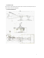
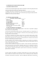
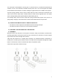
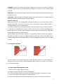
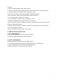
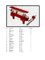
DRUM
MOWER
USER’S
MANUAL
1
APPENDICES
01 INDEX
02 INTRODUCTION
03 MACHINE DIMENSIONS
04 WORKING AND TECHNICAL SPECIFICATIONS
A-) WORKING SPECIFICATIONS
B-) TECHNICAL SPECIFICATIONS
05 MAIN INFORMATIONS FOR MACHINE
06 THE MATTERS BEING CAREFUL DURING TRANSPORT
07 ASSEMBLY AND WORKING
A-) ASSEMBLING OF MACHINE
B-) SAFESTARTUP
C-) CHANGING CUTTERS
08 OPERATING INSTRUCTIONS FOR SAFETY
09 MAINTENANCE INSTRUCTIONS
1-) DAILY MAINTENANCE
2-) ANNUAL MAINTENANCE
2
02-) INTRODUCTION
Drum mower is a kind of grass cutting machine which moved from tractor back pivot axle, free
rotary cuttered, and can be hanging type.
03-) MACHINE DIMENSIONS
3
04-) WORKING AND TECHNICAL SPECIFICATIONS
A-) WORKING SPECIFICATIONS
It cuts the crops requested height through cutters are located on reverse rotary pulleys and it has
3or4 times powered work value than its equal typed machine.
The biggest characteristic is putting down the crops over the floor regularly even by lower
powered tractor and even if the crops are wet or bended through clearing drum dimensions and
available free revolving of bottom ashtrays.
B-) TECHNICAL SPECIFICATIONS
___________ TECHNICAL SPECIFICATIONS___________
MODEL/TYPE
PULLEY NUMBER
CUTTER NUMBER
CUTTING WIDTH
BACK PIVOT AXLE REVOLUTION
PULLEY REVOLUTION
REQUIRED TRACTOR OUTPUT POWER
TOTAL WEIGHT
ST165
2
6 and 8
165cm
540 rpm
1920rpm
25 HP
370kg
05-) MAIN INFORMATIONS FOR MACHINE
It is connected with a three pointed hanging system to tractor and it is specified as pulleyed,
rotary cuttered, free cutting possibility.
There are three pointed hanging system, gear box, V belt-pulley system, two of cutter pulley, 6 of
leaf cutter, jointed axle to move carrying bars connected to three pointed hanging system and
carrying chassis on the Drum Mower.
The machine is designed as two different chassis. Both three pointed hanging system and beltpulley system from the first chassis of the machine. The gear box is the second chassis which
bear the drums at the same time. The gear box and first chassis are connected to each other with
two piece of slider bearing by the side of machine.
The drum activate to gear is formed by bearing. Furthermore two of chassis are connected to
three pointed hanging system with two of parallel steel bar which has spring pressed, and this
causes to adjust the length of machine.
The drum mower is activated from upper side of machine. The first movement is transmitted from
tractor back pivot axle to three grooved V belt-pulley system, then it is transmitted to gear box
and pulley axle through gears and last of all movement is transmitted to cutter disks. At the first
step, movement is transferred with belt-drum system and at the second step it is transferred to
gear box then to cutter disks.
Fill up the gearbox with suitable oil. Oil leakage is obtained with a joint. There are double of gear
which increase the movement comes from drum and two of double gear which transfer the
movement to cutter disks in the gear box. There are totally three-double gears in the gear box.
4
The movement is transmitted to conical gear of | second drum by a metal bar dimensioned as
1070mm, 25 mm. This metal bar is beared as three point over it. The conical gears are settled
reverse sided on that metal bar. So there is designed a grass barrel on the middle of the system.
There are spring pressed cutter on each of disks. Both two side of cutter has cut featured. The
cutter can be use for others when it wears because of disks revolve opposite side. The cutters
can be changed easily with a special spanner without disks pull out.
The working safety of drum mower is kept with spring pressed safety system. Also | there is a
spring safety coupling in main axle which movement transmitted from tractor pivot axle.
06.) THE MATTERS BEING CAREFUL DURING TRANSPORT
• The machine must be kept from hard blows and frictions during transport.
• The machine must be fix to flour to not move during transport.
07.) ASSEMBLY AND WORKING WITH THE MACHINE
A-) ASSEMBLY
Bring the tractor near machine to fix all parts of machine. Firstly fix left bottom connection bar,
secondly right bottom connection bar then the top connection bar to machine. Lift up the support
leg of machine and loose strength bar of tractor.
Take down the machine on a smooth place as being 5 cm diameter between continuation of
middle point of inside lag and outside of tractor rear right wheel, and tighten strength bars. Right
bottom connection bar must be as obtain that cutters are parallel to earth.
Follow same way before machine start-up.
5
POSITION 1: Take the machine right position. Approach the tractor to machine. Connect the
machine to tractor with three point after distance is adjusted. Connect the clutch of shaft to tractor
pivot axle.
POSITION 2: Open the pad lock after machine fix to tractor. Obtain the back movement of tractor
for cutting position.
POSITION 3: When the angle is 90 between machine and tractor that mean is cutting position, fix
it for cuffing position as automatic arm interlaces pad pin.
B-) SAFE START-UP
Before using machine, the oil named SAE 140 must be filled up to not overflow from container
which the plug near of gear box. At the end of each cut of grass, machine must be cleaned,
controlled oil lever, kept in a suitable place.
The cutters of disks must not be missed. Always equal sized cutters must be used for machine.
If cutter sizes are different, the balance of disks can be spoilt, can-cause breakdown and
machine life can be decrease. Keep the tractor revolution lower at the first start-up. After than
increase the revolution up to max 540 rpm.
Set the forward speed according to situation of crop and field. If disks experience any difficulty,
that cause to readjust strength for working situation so stop the tractor immediately in this
condition and get speed gear empty position. Abolish the difficulty and set the machine to start
up again.
C-) CHANGING CUTTERS
The wore cutters can be change easily with a cutter dismantle spanner. It must be lifted up to
cutter fix pin gets free when the cutters dismantled. When mantle of new cutters, be careful to
be cutting side is bottom.
08-) SAFE OPERATING INSTRUCTIONS
1. Stop the machine when setting and oiling.
2. Change the plastic protection of shaft if it is damaged.
3. Put on extra weight on the front of the tractor to balance between front side and rear side.
4. Put on the protection screen before the cutting operation.
5. Put on the shaft protection chain to side lifting bar, so shaft would not be turn because of
6
protection.
6. Get the machine parallel to earth before start-up.
7. There must not be any living creature between tractor and machine to start-up machine.
8. Turn the machine to side after machine is parallel to earth.
9. Do not over revolution as 540 rpm as stated in operating instructions.
10. Be careful that cutters are true settled after changing operation.
11. Use original cutters if olds are not run well.
12. Do not approach to machine without stopping the tractor.
13. Keep the machine transfer position when you do not use it.
14. Do not allow the persons to approach to machine, because the machine can throw some
stones or hard things to people.
15. Before cutting operations, the field or area must be cleaned from stones or hard things.
These can damage the machine.
16. Take care when you work in path or stony roads.
09-) MAINTENANCE INSTRUCTIONS
1. DAILY MAINTENANCE
a. Use the lubricating grease after every cutting operation.
b. Check the cutters and belts after cutting operations.
2. ANNUAL MAINTENANCE
a. Make a general cleaning at the end of reaping season.
b. Check the all parts of machine. Renew the damaged ones or unusable ones.
c. Use the lubricating grease to lubricate all of lubricating hole.
d. Keep the machine in a covered place after cleaning.
7
Ref.
Description
Code
1
2
3
4
5
6
7
8
9
10
11
12
13
14
15
16
17
18
19
20
21
22
23
24
25
26
27
28
Bolt
Spacing Tube
Plug
Alien Screw
Nut
Key
Ball Bearing
Spacing Tube
Bevel Gear
Circlip
Nut
Tab Washer
V-pu/ley
Raynel
Ball Bearing
Spacing Tube
Bevel Gear
Segman Yatagi
Circlip
Input Shaft
Key
Rulman Yatagi
Bevel Gear
Tab Washer
Nut
Drive Shaft
Main Frame
Oil Seal
ST M10х25
ST 101
ST 102
ST M10х25
ST M10
ST 103
ST 6305 2RS
ST 104
ST 105
ST 25х2
ST 30х1.5
ST 106
ST 107
ST 30х0.25
ST 6206 2RS
ST 108
ST 109
ST 110
ST 28х2
ST 111
ST 112
ST 113
ST 114
ST 115
ST 24х1.5
ST 116
ST 117
ST 45х62х8
Quantity
20
2
2
6
20
3
3
1
1
1
1
1
1
1
3
1
1
1
1
1
2
3
2
1
1
1
1
1
8
Ref.
1
2
3
4
5
6
7
8
9
10
11
12
13
14
15
16
17
18
19
20
21
22
23
24
25
26
27
Description
Nut
Muhafaza Baglanti Vidasi
Pin
Bolt
Nut
Lid for Pui/ey Guard
Pulley Guard
Bolt
Lift Link
Grease Nipple
Spacer
Nut
Sub frame
Transport Tube
Jack Stand
Nut
Pin
Slide for Breakaway
Spring
Washer
Bolt
Cotter Pin
Tab Washer
Bolt
Bolt
Ana Govde Baglanti Kolu
Spring Clip
Code
ST M10
ST 118
ST 119
ST M10х25
ST M10
ST 120
ST 121
ST M16х35
ST 122
ST 5/16
ST 123
ST M16
ST 124
ST 125
ST 126
ST 1/2
ST 127
ST 128
ST 129
ST 130
ST 1/2х175
ST 4/30
ST 131
ST M16х30
ST M16х45
ST 132
ST 133
Quantity
6
3
1
1
1
1
1
1
1
3
2
1
1
1
1
2
1
1
1
1
1
2
2
3
1
2
1
9
Ref.
1
2
3
4
5
6
7
8
9
10
11
12
13
14
15
16
17
18
19
20
21
22
23
24
25
26
Description
Lift Link
Ana Govde Baglanti Borusu
Lift Pivot Bracket
Spacer
Bolt
Spring
Cap
Lift Link
Cotter Pin
Washer
Spacer
Pin
8 mm Yayli Pim
Kot Pimi
Kol Pimi
Circlip
Washer
Pivot
Sleeve
Hitch Frame
Pin
Pin
Cotter Pin
Nut
Lock Lever
Bolt
Code
ST 134
ST 135
ST 136
ST 137
ST M10х85
ST 138
ST 139
ST 140
ST 4х30
ST 141
ST 142
ST 143
ST144
ST 145
ST 146
ST 60х2
ST 147
ST 148
ST 149
ST 150
ST 151
ST 152
ST 6/60
ST M10
ST 153
ST M10х75
Quantity
1
1
1
2
1
1
1
2
3
2
1
2
1
3
1
2
1
1
1
2
1
2
1
2
1
1
10
Ref.
1
2
3
4
5
6
7
8
9
10
11
12
13
14
15
16
17
Description
Shaft
Small V-pulley
V-belt
Washer
Nut
Tension Bolt
Nut
Tab Washer
Large V-pulley
Ball Bearing
Tab Washer
Drive Shaft
Key
Spacer
Housing
Cotter Pin
Pin
Code
ST 154
ST155
ST 17х2850
ST156
STM16
ST 158
ST 30х1.5
ST159
ST160
ST 6207 ZZ
ST 161
ST162
ST 163
ST164
ST165
ST 4х30
ST 166
Quantity
1
1
3
2
2
1
1
1
1
2
1
1
1
1
1
1
1
11
Ref.
1
2
3
4
5
6
7
8
9
10
11
12
13
14
15
16
17
18
19
20
21
22
23
24
25
26
Description
Alien Screw
Saucer
Blade
Percin
Blade Holder
Drum
Bijon
Hub
Ball Bearing
Ball Bearing
Dokum Rulman Yatagi
Celik Tas
3 mm Klip
Spring Clip
Hub
Nut
Tab Washer
Bevel Pinion
Oil Seal
Circlip
Ball Bearing
Drum Shaft
Ball Bearing
Circlip
Key
Key
Code
ST M 10х30I
ST 167
ST 168
ST 169
ST 170
ST 171
ST 172
ST 173
ST 6210 2RS
ST 51109
ST 174
ST 175
ST 176
ST 177
ST 178
ST 24х1.5
ST 179
ST 180
ST 40х62х10
ST 62х2
ST 6305 ZZ
ST 181
ST 6207
ST 35x2.5
ST 182
ST 183
Quantity
6
2
6
6
6
2
12
2
4
2
2
2
1
1
2
2
2
2
2
2
2
2
2
2
2
2
12
Ref.
1
2
3
4
5
6
Description
Protection Cover
Bo/f
Strip for Protection Guard
Guard Tube
Nut
Protection Guard
Code
ST 184
ST M3/8x20
ST 185
ST 186
ST M3/8
ST 187
Quantity
1
8
2
1
8
2
13