1
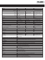
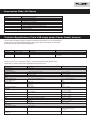
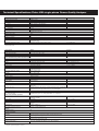
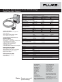
Fluke 430 Series
three-phase and Fluke 43B
single-phase Power Quality
Analyzers
Technical Data
Analyze your power network quickly
In industry, healthcare, and business – in fact wherever electrical and
electronic equipment is indispensable – power quality plays a critical role
in maintaining continuity. Non-linear loads, switching, load changes and
equipment problems can result in poor power quality. Poor power quality
is not only costly in terms of wasted energy and unnecessary downtime,
it’s also dangerous and increases risk of equipment failure.
Fluke has an unrivalled range of power quality analyzers to help you
maintain high-quality power systems. The tools give you the power to
analyze every parameter, power-related event or anomaly faster, safer
and in more detail than ever before.
The range comprises the Fluke 430 Series three-phase power quality
analyzers and the 43B single-phase power quality analyzer.
Power Quality Selection Table
434
433
43B*
Single-phase
1 voltage and 1 current
Three-phase
4 voltage and 4 current
(for 3 phases and neutral)
Application
Inputs
Measurements
Vrms, Arms, Hz, W, VAR, VA, PF, Cos ϕ (DPF), Crest Factors
Harmonics and THD (V,A,W), k-factor
Inter-harmonics
kWh and kVARh, kVAh, demand interval
Flicker (Plt, Pst, PF5)
Unbalance
Recorder/ AutoTrend
System-Monitor
Real time scope/Phasor diagrams
Dips and swells/Half cycle based
Transient displaycapture
Inrush current
EN50160 compliance
IEC61000-4-30, -4-7, -4-15 compliance
●
●
●
●
●
●
●/●
●
●/●
●/●
●
●
●
●
●
●
Optional*
Optional*
●
●
●/●
●
●/●
●/●
Optional*
Optional*
●
●
●
●
●
●
●
●
●/●/●/●
●
-
Built-in general purpose Scope and DMM
Memory (screens/data)
50/10
25/5 standard
50/10 optional*
Optional*
●
20 for screens and data
FlukeView software and interface cable
EN61010 safety rating
* Optional functionality can be added with upgrade kit. For details see ordering information.
●
600 V CAT IV/1000 V CAT III
Depending
on configuration*
600 V CAT III
Technical Specifications Fluke 430 Series three-phase Power Quality Analyzers
Input characteristics
Voltage inputs
Number of inputs
Maximum input voltage
Maximum peak voltage
Input impedance
Bandwidth
Scaling
Current inputs
Number of inputs
Type
Range
4 (3 phases + neutral)
1000 Vrms
6 kV
4 MΩ // 5 pF
9 kHz, up to 100 kHz for transient display
1:1, 10:1, 100:1, 1000:1 and variable
4 (3 phases + neutral)
Clamp on current transformer with mV output
1..400 Arms with included clamps (i400s)
0.1..3000 Arms with optional clamps
50 kΩ
9 kHz
0.1, 1, 10, 100, 1000 mV/A and variable
40..70 Hz
Input impedance
Bandwidth
Scaling
Nominal frequency
Sampling system
Resolution
16 bit analog to digital converter on 8 channels
Maximum sampling speed
RMS sampling
PLL synchronization
Display modes
Waveform display
200kS/s on each channel simultaneously
5000 samples on 10/122 cycles according IEC 61000-4-30
4096 samples on 10/122 cycles according IEC 61000-4-7
Available in Scope and Transient mode
Captures 8 waveforms simultaneously
Display update rate 5x per second
Up to 10/12 times horizontal zoom
Cursors: Single vertical line showing min, max, avg reading at cursor position.
Shows real time phasor diagram
Available in Scope and Unbalance mode
Display update rate 5x per second
Available in Volts/Amps/Hertz, Harmonics, Power & Energy, Flicker and Unbalance mode.
Available in Volts/Amps/Hertz, Dips & Swells, Harmonics, Power & Energy, Flicker, Unbalance, Inrush and Monitor mode
Cursors: single vertical line showing with min, max, avg reading at cursor position.
Available in Harmonics and Monitor mode
Available in Dips & Swells and Monitor mode
Phasor
Matrix readings
AutoTrend graph
Bargraph
Eventlist
Measurement modes
Scope
Volts/Amps/Hertz
Dips and Swells
Vrms, Arms, Vcursor, Acursor, Vfund, Afund, Hz, V phase angles, A phase angles
Vrms, Vpk, V Crest Factor, Arms, Apk, A Crest Factor, Hz
Vrms1/2 , Arms1/2
Captures up to 1000 events with date, time, duration, magnitude and phase identification with programmable thresholds
Harmonic Volts, THD Volt, Harmonic Amps, THD Amps, K Amps, Harmonic Watts, THD Watts, K Watts, Interharmonic Volts4,
Interharmonic Amps4
(relative to fundamental or to total rms)
Watts, VA, VAR, Power factor, Cos ϕ / DPF, Arms, Vrms, kWh, kVAh, KVARh, peak demand interval using trend, KYZ revenue
meter verification via optional input
Pst(1min), Pst, Plt, PF5, Vrms1/2 , Arms1/2 , Dc, Dmax, TDEX
Vneg, Vzero, Aneg, Azero, Vfund, Afund, Hz, V phase angles, A phase angles
Vrms, Arms, Vcursor, Acursor
Inrush Current, Inrush duration, Arms1/2, Vrms1/2
Vrms, Arms, Harmonic Volts, THD Volts, Plt, Vrms1/2 , Arms1/2 , Vneg, Hz, dips and swells, unbalance. All parameters are
measured simultaneously in accordance with EN50160.
Using Flagging to indicate unreliable readings according IEC61000-4-30.
Harmonics
DC, 1 … 50
Power and Energy4
Flicker
Unbalance
Transients4
Inrush Currents4
System Monitor
Accuracy, resolution and range
Volt/Amps/Hertz
Vrms (AC+DC)
Vpk
CFV
Arms (AC+DC)
Apk
CFA
Hz
Dips and swells
Vrms1/2 (AC+DC)
Arms1/2 (AC+DC)
Threshold levels
Duration
with included clamps
using 1mV/A scaling
using 1mV/A scaling
50Hz nominal
60Hz nominal
with included clamps
Measurement range
1…1000 Vrms
1…1400 Vpk
1.0 ... > 2.8
0…20,000 Arms1
0…400 Arms
0 - 5500 Apk
1 … 10
42.50 ... 57.50 Hz
51.00 ... 69.00 Hz
Resolution
0.1 Vrms
1V
0.1
0,001…10 Arms1
0.1 and 1 Arms
10A
0.1
0.01 Hz
0.01 Hz
0.0% ….100% of nominal voltage
0.1 Vrms
0 … 20,000 Arms1
0,001 Arms…10 Arms
0 … 400 Arms
0.1 Arms and 1 Arms
Programmable in percent of nominal voltage
hhh,mm,ss,mmm with half-cycle cycle time resolution
Accuracy
± 0.5% of nominal voltage
5% of nominal voltage
± 5%
± 1% of reading ± 5 counts3
±
±
±
±
5%
5%
0.1% of nominal frequency
0.1% of nominal frequency
± 1% of nominal voltage
± 1% of reading ± 5 counts3
®
Measurement range
Harmonics
Harmonic selection (n)
Inter-Harmonic selection
Vrms
Vrms
Relative (%f):
Absolute:
Relative (%f):
Absolute:
Watts
Relative:
Absolute:
DC voltage
Relative:
Absolute:
THD
Hz
Phase angle
Power and Energy
Watt
VA
VAR
kWh
kVA
kVAR
Power Factor
Cos ϕ / DPF
Flicker
Pst (1min), Pst, Plt, PF5 instantenous Flicker
Dc%, Dmax% and Time d(t) exceeds limits.
As described per IEC 61000-3-3
Unbalance
Volts
Current
Transient capture
Volts
Minimum detect duration
Sampling rate
Inrush mode
Arms (AC+DC)
Inrush Duration
Trend recording
Method
DC, 1..50
Off, 1..49
0.0 … 100.0%,
0.0 … 1000 Vrms
0.0 … 100.0%,
0.0 … 4000 mV x selected clamp
scaling
0.0 … 100.0%
depends on selected clamp and
voltage scaling
0.0 … 100.0%
0.0 … 1000V
0.0 … 100.0 %
0 … 3500 Hz
-360º ... +360º
Resolution
0.1%,
0.1 Vrms
0.1%,
1 mVrms x selected clamp
scaling
0.1%
Accuracy
±
±
±
±
0.1% ± n x 0.1% (± 0.4% for %r)
5% of reading ± 2 counts
0.1% ± n x 0.1% (± 0.4% for %r)
5% of reading ± 5 counts
0.1%
0.1V
0.1%
1 Hz
1º
±
±
±
±
±
±
±
±
n x 2%
5% of reading ± n x 2% of reading,
10 counts
1%
5% of reading ± 10 counts
2.5%
1Hz
n x 1.5º
1.0 W … 20.00 MW1
1.0 VA … 20.00 MVA1
1.0 VAR … 20.00 MVAR1
0.1 W … 1 kW1
0.1 VA … 1 kVA1
0.1 VAR … 1 kVAR1
± 1.5% of reading ± 10 counts3
± 1.5% of reading ± 10 counts3
± 1.5% of reading ± 10 counts3
00.00 kWhr…200.0 GWhr1
00.00 kVAhr…200.0 GVAhr1
00.00 kVARhr … 200.0 GVARhr1
0…1
0…1
0.01 Whr….100 Whr1
0.01 VAhr….100 VAhr1
0.01 VARhr….100 VARhr1
0.01
0.01
±
±
±
±
±
0.00 … 20.00
0.01
0.0 … ± 100.0% for Dc% and Dmax%
... 9.999s for Time ± 1% for Time
0.1% for Dc% and Dmax% and 10 ms
for Time
Within ±5% of tabulated values
according IEC61000-4-15
± 1% for Dc% and Dmax% and 20 ms
for Time
0.0 … 5.0%
0.0 … 20%
0.1%
0.1%
± 0.5%
± 1%
± 6000 Vpk
1V
± 15% of cursor reading
± 2.5% of Vrms
0.001.. 10 Arms1
10 ms
± 1% of meas ± 5 counts
± 20 ms (Fnominal = 50 Hz)
1.5% of reading ± 10 counts3
1.5% of reading ± 10 counts3
1.5% of reading ± 10 counts3
0.033
0.033
5 µs
200 kS/s
0.000 … 20.00 kArms1
mm:ss:mmm between 7.5 s …
30 m selectable
AutoTrend automatically records min, max and average values over time for all readings being displayed for the 3 phases and
neutral simultaneously.
Volts/Amps/Hertz, Harmonics, Power & Energy, Flicker and Unbalance mode
Sampling
5 readings/sec continuous sampling per channel
Memory
1800 min, max and avg points for each reading
Recording time
From 30 min with 1 second display resolution up to 450 days with 6 hour display resolution
Zoom
Up to 6x horizontal zoom
Dips & Swells mode
Sampling
100/1202 readings/sec continuous sampling per channel
Memory
3600 min, max and avg points for each reading
Recording time
From 90 sec with 25 msec display resolution up to 450 days with 3 hr display resolution
Zoom
Up to 12x horizontal zoom
Inrush Currents and Flicker PF5 mode
Sampling
100/1202 readings/sec continuous sampling per channel
Memory
3600 min, max and avg points for each reading
Recording time
From 7.5 sec with 25 msec display resolution up to 30 min with 500msec display resolution for Inrush measurements and
up to 2.5 hr with 2.5 sec display resolution for PF5 recordings
Zoom
Up to 12x horizontal zoom
Monitor mode
Sampling
Combination of 5 readings/sec and 100/1202 readings/sec continuous sampling per channel depending on the parameter
measured
Recording time
Up to 1 week with 10 min resoluton
Memory
1008 min, max and avg points for each reading
Limits
According EN50160 or customer definable
Measurement method
Vrms, Arms
10/122 cycle contiguous non overlapping intervals using 500/4162 samples per cycle in accordance with IEC 61000-4-30
Vpeak, Apeak
Absolute highest sample value within 10/122 cycle interval with 40µs sample resolution
V Crest Factor
Measures ratio between the Vpeak and Vrms
A Crest Factor
Measures ratio between the Apeak and Arms
Hz
Measured every 10 sec in accordance with IEC61000-4-30
Vrms1/2 ,Arms1/2
Value is measured over 1 cycle, commencing at a fundamental zero crossing, and refreshed each half-cycle. This technique is
independent for each channel in accordance with IEC 61000-4-30
Technical Specifications Fluke 430 Series three-phase Power Quality Analyzers
Measurement method (continued)
Harmonics
Watt
VA
VAR
Power Factor
Cos ϕ / DPF
Unbalance
Flicker
Transient capture
Inrush current
General Specifications
Case
Design
Drip and dust proof
Shock and Vibration
Display
Size
Resolution
Contrast and brightness
Memory
Screens
Data
Limit templates
Real-time clock
Mechanical
Size
Weight
Power
Line power
Battery power
Battery operating time
Battery charging time
Power saving
Standards
Measurement methods used
Power Quality
Flicker
Harmonics
Safety
Compliance
Max voltage on banana input
Max voltage on current BNC input
Environmental
Operating temperature
Storage temperature
Humidity
Maximum operating altitude
Maximum storage altitude
Warranty
Calculated from 10/12-cycle gapless harmonic group measurements on Voltage and Amps according to IEC 61000-4-7
Selectable Total or Fundamental real power display
Calculates average value of instantaneous power over 10/12 cycle period for each phase Total Active Power
PT =P1 + P2 + P3
Selectable Total or Fundamental apparent power display
Calculates apparent power using Vrms x Arms value over 10/12 cycle period
Total Apparent Power is root mean square of real and apparent power
Selectable Total of Fundamental reactive power display
Calculates reactive power as root of VA squared minus Watt squared over 10/12 cycle period. Capacitive and inductive load is
indicated with capacitor and inductor icons
Calculated Watt / VA
Cos of angle between fundamental voltage and current
The supply voltage unbalance is evaluated using the method of symmetrical components according to IEC61000-4-30
According to IEC 61000-4-15 Flickermeter - Functional and design specification.
Includes 230V 50Hz lamp and 120V 60Hz lamp models
Captures waveform triggered on signal envelope.
Additionally triggers on dips, swells, interruptions and Amps level as specified by IEC61000-4-30
The inrush current begins when the Arms half cycle rises above the inrush threshold, and ends when the Arms half cycle
rms is equal to or below the inrush threshold minus a user-selected hysteresis value. The measurement is the square root of
the mean of the squared Arms half cycle values measured during the inrush duration.
Each half-cycle interval is contiguous and non-overlapping as recommended by IEC 61000-4-30.
Markers indicate inrush duration. Cursors allow measurement of peak Arms half cycle.
Rugged, shock proof with integrated protective holster
IP51 according to IEC60529 when used in tilt stand position
Shock 30g, Vibration: 3g Sinusoid, Random 0.03g2/Hz according to MIL-PRF-28800F Class 2
Bright Full-Color LCD with CCFL backlight, 80cd/m2
115.2 x 86.4 mm
320 x 240 pixels
User adjustable, temperature compensated
50 screen memories on Fluke 434
25 screen memories on Fluke 433
10 data memories for storing data including recordings on Fluke 434
5 data memories for storing data including recordings on Fluke 433
2 preprogrammed, 2 administrator (programmable via FlukeView), 2 user locations
Time and date stamp for AutoTrend, Transient display and SystemMonitor
256 x 169 x 64 mm
2 kg
Switchable 115V, 230V adapter with country specific plug
Rechargeable NiMH (installed)
> 7 hours
4 hours
Adjustable time for dimmed backlight with on screen power indicator
IEC61000-4-30 class A
EN50160
IEC 61000-4-15
IEC 61000-4-7
IEC/EN61010-1 (2nd edition) pollution degree 2;
CAN/CSA C22.2 No 101.1
ANSI/ISA S82.01
1000 V CAT III / 600 V CAT IV
42 Vpeak
0 °C to +50 °C
-20 °C to +60 °C
10 .. 30 °C: 95% RH non condensing
30 .. 40 °C: 75% RH non condensing
40 .. 50 °C: 45% RH non condensing
3000 m. Derate to 1000 V CAT II / 600 V CAT III / 300 V CAT IV above 2000 m
12 km
3 years on mainframe, 1 year on included accessories
Ordering Information
Fluke 433
Power Quality Analyzer (three-phase)
Fluke 434
Power Quality Analyzer (three-phase)
Fluke 433 UGK Upgrade Kit for Fluke 433
(includes 433AF, OC4USB and SW43W)
Fluke 433AF
Advanced Functions Upgrade Kit for Fluke 433
OC4USB
Serial Interface Adapter/Cable (USB)
PM9080
Serial Interface Adapter/Cable (RS232)
SW43W
FlukeView Software
1
2
3
4
depending clamp scaling
50Hz/60Hz nominal frequency according to IEC 61000-4-30
Add clamp accuracy
The advanced functions: interharmonics, Energy, Transients and Inrush are
optional for the Fluke 433 and standard available on the Fluke 434
®
Accessories Fluke 430 Series
Accessories
Included
C430 Hard case with clamp holders
i400s current clamps (4)
TLS430 Test leads and alligator clips (4 black, 1 green)
BP190 NiMH Battery pack (installed)
BC430 Battery charger/line voltage adapter
SW43W FlukeView Software (Fluke 434 only)
OC4USB Serial interface adapter cable (USB) (Fluke 434 only)
WC100 Color localization set
Getting Started (printed)
User Manual (CD-ROM)
Technical Specifications Fluke 43B single-phase Power Quality Analyzer
The Fluke 43B Power Quality Analyzer is optimized for industrial measurements on the 50 Hz fundamental
frequency. Since its usable fundamental frequency range extends from 10 Hz to 400 Hz, the 43B is ideal
for industrial, aviation, marine and railway applications.
Mode
Volt Amp Hz
Power
Harmonics
Usable bandwidth
10 Hz … 3.5 kHz
20Hz … 2 kHz
10 Hz … 3.5 kHz
Harmonics on 400 Hz fundamental
9th harmonic
5th harmonic
9th harmonic
Typical accuracy for 400 Hz fundamental
5%
10%
10% Channel 1
50% Channel 2
Note: Current harmonics measurements can be done via channel 1 with improved accuracy
Accuracies are stated as ± (percentage of reading + counts) without probes unless otherwise noted.
Specifications are valid for signals with a fundamental between 40 and 70 Hz.
Input Characteristics
Input impedance
Voltage rating
Volt / Amps / Hertz
True-rms voltage (AC+DC)
True-rms current (AC+DC)
Frequency
CF Crest Factor
Power
W, VA, VAR Reactive Power
1-phase and 3-phase,3
conductor balanced loads
PF Power Factor
DPF Displacement Power Factor
Hz Frequency Fundamental
Harmonics
Volts, Amps, Watts
Ranges
1 MΩ, 20 pF
600 Vrms, CAT III
Accuracy
5.000 V, 50.00 V, 500.0 V, 1250 V*
50.00 A, 500.0 A, 5.000 kA, 50.00 kA, 1250 kA
10.0 Hz to 15.0 kHz
1.0 to 10.0
±
±
±
±
250 W 2.50 kW, 25.0 kW, 250 kW, 2.50
MW, 25 MW, 250 MW, 625 MW, 1.56 GW
± (2 % + 6 counts) Total Power
± (4 % + 4 counts) Fundamental
Power
± 0.04
not specified
± 0.04
± 0.03
± (0.5 % + 2 counts)
0.00
0.00
0.25
0.90
40.0
to
to
to
to
to
1.00
0.25
0.90
1.00
70.0 Hz
Fundamental
2 to 31st Harmonic
32 to 51st Harmonic
Frequency of fundamental
Phase
K-Factor (Amps & Watts)
THD
Sags & Swells
Recording times (selectable)
Vrms Actual, Vrms max,
min (AC + DC)
Arms Actual, Arms max,
min (AC + DC)
40 Hz to 70 Hz
Volt & Amps (between Fund. & Harmonic)
Watts (between Volt Fund. & Amps
Harmonic )
1.0 to 30.0
0.00 to 99.99
4 min to 16 days
5.000 V, 50.00 V 500.0 V, 1250 V*
50.00 A, 500.0 A, 5.000 kA, 50,00 kA
(1 % + 10 counts)
(1 % + 10 counts)
(0.5 % +2 counts)
(5% + 1 count)
V,A ± (3 % + 2 counts),
W ± (5 % + 2 counts)
V,A ± (5 % + 3 counts),
W ± (10 % + 10 counts)
V,A ± (15 % + 5 counts),
W ± (30 % + 5 counts)
± 0.25 Hz
2nd (± 3°) … 51st (±15°)
Fund (± 5°) … 51st (±15°)
±10 %
± (3% + 8 counts)
Readings ±(2% +10 counts)
Cursor readings ± (2% + 12 counts)
Cursor Readings Average ±(2%
+10 counts)
Technical Specifications Fluke 43B single-phase Power Quality Analyzer
Recording
Recording times (selectable)
Parameters
V/A/Hz
Power
Harmonics
Ohms
Temperature
Scope
Transients
Minimum pulse width
Useful bandwidth input 1
Number of transients
Voltage threshold settings
Reference signal
Vpeak min, Vpeak max at cursor
Ranges
Accuracy
4 min to 16 days
Choose one or two parameters from one of the groups below
Line Voltage, Current, Frequency
Watts, VA, VAR, PF, DPF, Frequency
THD, Volt(Fund. & Harmonic), Amps(F&H) Watts(F&H) Freq.(H), %(H) of total, Phase(H), KF
Ohms, Diode, Continuity, Capacitance
°C or °F
DC Voltage, DC Current, AC Voltage, AC Current, Frequency, Pulse Width + or -,Phase, Duty cycle + or -, Peak max, Peak min,
Peak min-max, Crest Factor
40 ns
DC to 1 MHz (with test leads TL24)
40
20%, 50%, 100%, 200% above or below reference signal
After START, the Vrms and frequency of the signal are measured. From these data a pure sinewave is calculated as reference
for threshold setting.
10 V, 25 V, 50 V, 125 V, 250 V, 500 V, 1250 V
± 5% of full scale
*Rated 600V CAT III
Inrush Current
Ranges
Current ranges (selectable)
1 A, 5 A, 10 A, 50 A, 100 A, 500 A, 1000 A
Inrush times (selectable)
l s, 5 s, 10 s, 50 s, 100 s, 5 min
Cursor readings
A peak max at cursor 1 and cursor 2
Time between cursors**
4 to 235 pixels
Scope, dual channel scope with measurement reading
Input Impedance
Input 1
1 MΩ//12 pF; with BB120: 20 pF
Input 2
1 MΩ//10 pF; with BB120: 18 pF
Vertical
Voltage ranges
50 mV/div to 500V/div
Vertical sensitivity, resolution
5 mV/div to 500V/div, 8 bit (256 levels)
Bandwidth channel [1] (voltage)
DC to 20 MHz at inputs, or with BB120 and VPS40 (standard with Fluke 43B);
1 MHz with TL24 Leads
Bandwidth channel [2] (current)
DC to 15 kHz at inputs
10 kHz with supplied current clamps
Coupling
DC, AC (10 Hz -3 dB)
Horizontal
TimeBase modes
Normal, roll, single
TimeBase ranges
60 s/div to 20 ns/div
Sampling rate
25 MS/s
Record length
512 per channel
(min / max samples)
Trigger source
Input 1 or Input 2 or Automatic selection
Trigger Mode
Automatic Connect-and-View™, Free Run,
Single Shot.
Connect-and-View™
Advanced automatic triggering that recognizes signal patterns and automatically
adjusts triggering, timebase and amplitude. Automatically displays stable pictures
of complex and dynamic signals like motor drive and control signals.
Pre-trigger
Up to 10 divisions
Measurement readings,
Volts & Amps (DC, AC, AC + DCrms, Peak max, Peak min, Peak min / max ),
per channel selectable
Frequency, Duty cycle + or - , Phase, Pulse Width + or -, Crest factor
Ohms, Diode, Continuity, Capacitance
Ohms
500.0 Ω 5.000 kΩ, 50.00 kΩ, 500.0 kΩ,
5.000 MΩ, 30.00 MΩ
Diode voltage
0 to 3.000 V
Continuity, shorts > 1 ms
Beeper on at < 30Ω ± 5Ω,
Capacitance
50.00 nF, 500.0 nF, 5.000 µF, 50.00 µF,
500.0 µF
Temperature***
-100.0 °C to 400.0 °C,
-200.0 °F to 800.0 °F
Max current, max open circuit volt.
0.5 mA, < 4 V (all functions above)
Memory
Number of screens
20
General specifications
Optical Isolated RS-232 Interface
To printer
Supports HP LaserJet, DeskJet, Epson FX/LQ and Postscript printers with
optional PAC91 Printer Adapter Cable
To PC
FlukeView® Power Quality Analyzer software with PM9080 Interface
Adapter included with 43B and 43Kit
®
FlukeView Power Quality Software
Hardware requirements
PC or 100% compatible with Windows 95, 98, Me, 2000, NT4.0.
** 1 pixel = inrush time/250
*** Requires optional temperature accessory
Accuracy
± 5% of full scale
± (0.2% + 2 pixels)
± 2 pF; with BB120 ±3 pF
± 2 pF; with BB120 ±3 pF
± (1% + 2 pixels)
± (0.4% + 1 pixel)
± (0.6% +5 counts)
± (2% +5 counts)
±(2% +10 counts)
±(0.5% +5 counts)
®
Power
Line voltage adapter/battery charger included
Installed battery
Rechargeable NiCd pack (4 to 6 Vdc)
Operating time
4 hours
Charging time
4 hours (unit OFF) 12 hours (unit ON)
Refresh Cycle
8 to 14 hours (to keep NiCd battery capacity optimal)
Environmental
Operating Temperature
0ºC to 50ºC (32ºF to 122ºF)
Shock & Vibration
MIL 28800E, Type 3, Class III, Style B
Case
IP51 (dust, drip water proof)
Mechanical Data
Size (H x W x D)
232 x 115 x 50 mm
Weight
1.1 kg
Safety
For measurements on 600 Vrms Category III installations, Pollution Degree 2 in accordance with
EN61010-1 (1993) (IEC1010-1)
ANSI/ISA S82.01-1994
CAN/CSA-C22.2 No. 1010.1-92
UL3111-1
Surge protection
6 kV on input 1 and 2
Floating measurements
600 Vrms from any terminal to ground
Warranty
3 years parts and labor on Fluke 43B, 1 year on accessories
Ordering Information
Fluke 43Basic Power Quality Analyzer (Single-phase)
Fluke 43B Power Quality Analyzer (Single-phase)
Fluke 43Kit Power Quality Analyzer (Single-phase)
Standard available in all models
Fluke 43B Power Quality Analyzer
BP120 NiCd Battery Pack (installed)
PM 8907 Battery Charger/Line Voltage Adapter
TL24 Test Leads
AC20 Industrial Test Clips
TP4 Slim Reach Test Probe Set (4 mm)
BB120 Banana-to-BNC Adapter Plug
Model difference
i200s AC Current Clamp (200 A)
80i500s AC Current Clamp (500 A)
SW43W FlukeView® Software for Windows
PM 9080 Serial Interface/Adapter Cable
C120 Hard Case
TP1 Slim Reach Test Probe Set (flat blade)
AC85 Large Jaw Alligator Clips
Power Quality Video
Users Manual / Application Guide
Manual CD 43B
Promotional Model Numbers
VPS40 Voltage Probe
Fluke 61 IR Thermometer
Fluke VR101S Voltage Event Recorder System
43Basic
●
●
●
●
●
●
●
43B
●
●
●
●
●
●
●
43Kit
●
●
●
●
●
●
●
●
●
●
●
●
●
●
●
●
●
●
●
●
●
●
●
●
●
●
●
●
Technical Specifications Fluke VR101S Voltage
Event Recorder System
VR10
1 VOLTAGE
EV
RDER ENT
RECO
Electrical
(voltage versions, plug style, and manual languages are determined by country)
Voltage Version
Operating range
Nominal frequencies
120 V
70 V to 140 V
50 Hz or 60 Hz
230 V
140 V to 270 V
50 Hz or 60 Hz
Power consumption
2W
3W
Sags, Swells and Outage Measurements
Voltage Version
Range
120 V Hot-to-neutral
0 to 200 V rms
Neutral-to-ground
3 to 200 V rms
230 V Hot-to-neutral
0 to 400 V rms
Neutral-to-ground
3 to 120 V rms
Accuracy
±2 V rms
±2 V rms
±4 V rms
±2 V rms
Resolution
1 V rms
1 V rms
2 V rms
1 V rms
Range
100 to 2500 V peak
50 to 2500 V peak
20° to 180°
200° to 360°
Accuracy
±(10% reading +10 V)
±(10% reading +10 V)
±1°
Resolution
10 V
10 V
1°
Range
45 to 65 Hz
Accuracy
±0.1 Hz (3 cycles min)
Resolution
0.1 Hz
Transient Measurements
Hot-to-neutral
Neutral-to-ground
Phase angle
Ordering Information
(Note: At least one VR101S is required for
proper operation)
VR101S Voltage Event Recorder System
VR101 Voltage Event Recorder
Computer Hardware Requirements for
EventView software
IBM PC or 100% compatible,
with Windows® 3.1 or Windows 95/98/NT/XP
or 2000 installed and operating
At least one free RS-232 serial port
A pointing device (recommended)
2 MB hard drive space
4 MB RAM (8 MB for Windows 95/98 or higher)
Included Accessories VR101S
VR101 Voltage Event Recorder,
Optical interface cable, 9-to-25 pin adapter,
EventView Software on two 31⁄2 inch
floppies, Users Manual
Included Accessories VR101
VR101 Voltage Event Recorder,
Instruction Sheet
Minimum pulse width: 1 µs
Frequency Measurements
Time Measurements: Events < 1 second
Accuracy
Hot-to-neutral
±0.5 cycles
Neutral-to-ground
±1 cycle
Resolution
0.5 cycles
1 cycle
Events ≥1 second (time stamp)
Accuracy
±(2 sec/day + 8 sec)
General Specifications
Memory size
Power
Battery type
Battery life
Mechanical
Physical size
Weight
Environmental
Operating temperature
Relative Humidity
Safety
Warranty
Resolution
8 sec
4000 events
3.5V lithium (non-replaceable)
7 years
85 mm x 68 mm x 35 mm
120g
-40 to 70°C
0 to 95% (non-condensing)
CSA Certification pending, CSA-NRTL (to UL 3111) certification pending,
Complies with requirements of EN61010-1:1993
1 year
Fluke Corporation
P.O. Box 9090
Everett, WA USA 98206
Fluke Europe B.V.
P.O. Box 1186
5602 BD Eindhoven
The Netherlands
Fluke (UK) Ltd
52 Hurricane Way
Norwich
Norfolk
NR6 6JB
United Kingdom
Tel.: 0207 942 0700
Fax: 0207 942 0701
E-mail: [email protected]
Fluke. Keeping your world
up and running.
Visit us on the world wide web at:
http://www.fluke.co.uk
For more information call:
In the U.S.A. (800) 443-5853
or Fax (425) 456-5116
In Europe/M-East/Africa
+31 (0)40 2 675 200
or Fax +31 (0)40 2 675 222
In Canada (905) 890-7600
or Fax (905) 890-6866
From other countries
+1 (425) 456-5500
or Fax +1 (425) 456-5116
Visit us on the world wide web at:
http://www.fluke.com
© Copyright 2004 Fluke Corporation.
All rights reserved.
Printed in the Netherlands 09/04
Data subject to alteration without notice.
Pub_ID: 10808-eng