1
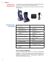
iridium SatDOCK 9555 Installation & User Manual Suitable for the Iridium 9555 Portable Satellite Telephone REMOTE SATELLITE SYSTEMS 1455 North Dutton Ave Suite A Santa Rosa, CA 95401 (888) 989-8199 www.remotesatellite.com [email protected] Beam Communications Pty Ltd iridium SatDOCK 9555 Installation and User Manual Version 1.0 Product name: SatDOCK 9555 Manual revision: 01 Part Number: USRMAN004501 Release date: March 2009 BEAM Communications Pty Ltd 8 Anzed Court, Mulgrave, Victoria, 3170, AUSTRALIA Information furnished by BEAM Communications Pty Ltd (BEAM) is believed to be accurate and reliable. However, no responsibility is assumed by BEAM for its use, or for any infringement of patents or other rights of third parties, which may result from its use. No license is granted by implication or otherwise under any patent or patent rights of BEAM. BEAM reserves the right to change specifications at any time without notice. Copyright © 2009 BEAM Communications Pty Ltd. All rights reserved Package Contents Check that your SatDOCK 9555 package contains: 1 x SatDOCK 9555 Docking Station 1 x Hands Free Interface (HFI) module 1 x Speaker 1 x Microphone 1 x 3-wire Power cable harness / 2 Fuses 1 x RAM bracket 3 x M4 Screws Mounting Adhesive / Velcro User Manual Quick Start Guide Optional Accessories The following optional accessories are available for your SatDOCK 9555 • Intelligent handset (uses RJ45 port) • Antenna Cable • Antenna See your Service Provider for pricing and availability of these quality BEAM accessories. User Information Please record your serial number here for future reference: Model: SatDOCK 9555 Serial no.: This number can be copied from the white label on the SatDOCK 9555 Eg. SK500001 BLANK PAGE 4 SatDOCK 9555 Installation & User Manual Contents Safety Information 6 About Beam Communications 11 About this Equipment 12 SATDOCK 9555 FEATURES 12 Installation Guidelines 14 EQUIPMENT OVERVIEW 15 UNPACKING & TESTING 17 INSTALLATION PROCEDURE 18 INSTALLING THE SATDOCK CRADLE 18 SATDOCK INSTALLATION STEPS 19 INSTALLING HANDSFREE INTERFACE UNIT (HFI) 19 ANTENNA CONNECTION 21 INSTALLING THE DIRECTIONAL MICROPHONE 22 INSTALLING THE SPEAKER 23 CHECKING PERFORMANCE AFTER INSTALLATION 23 SatDOCK 9555 Usage 25 OPERATION OF THE SATDOCK 26 REMOVING THE 9555 FROM VEHICLE 26 CHARGING THE IRIDIUM 9555 HANDSET IN SATDOCK 26 MUTE FUNCTIONALITY & EARPIECE-JACK MODE 27 SATDOCK INTERFACE LED 27 DATA COMMUNICATIONS 28 USING THE RS232 COMMUNICATION PORT 30 USING THE USB DATA PORT 31 USING THE LINE IN/OUT 32 CONNECTING AN INTELLIGENT HANDSET (OPTIONAL) 33 IRIDIUM 9555 DISPLAY DEFINITIONS 34 POWER-ON MESSAGES 35 Assuring Quality of Iridium Service 36 Specification Summary 38 ELECTRICAL & ENVIRONMENTAL SPECIFICATIONS 38 RS232 (COM PORT) SPECIFICATION 39 CRADLE MOUNTING DIMENSIONS (Millimeters) 40 HANDS FREE INTERFACE (HFI) MOUNTING DIMENSIONS (Millimeters) 41 Trouble Shooting 42 Beam Warranty Conditions 46 5 Safety Information NOTE: Please read the following information carefully before installing and using the Beam SatDOCK 9555. Failing to follow instructions may compromise the safety of the product and may result in personal injury and/or equipment damage. Please consult your supplier if you have any further questions. Your SatDOCK 9555 is a low power docking station for the 9555 handset; when ON, it will charge the 9555 handset whilst docked in the SatDOCK 9555. Refer to the appropriate section of this SatDOCK 9555 Installation & User Manual for additional safety information. • Store the system in a cool and dry area. • Do not submerge the system in water. • Do not place foreign metal objects or debris in the system. If debris fall into the system, please return to factory for service. WARNING: DO NOT open equipment. There are no user-serviceable parts inside. If a DC power supply is to be used, its output must comply with the Safety Extra Low Voltage (SELV) requirements of IEC60950. All connectors sockets must only be connected to equipment ports which comply with the Safety Extra Low Voltage (SELV) requirements of IEC60950. WARNING: POTENTIALLY EXPLOSIVE ATMOSPHERES 1. Turn your phone OFF and DO NOT remove your battery or remove the 9555 handset from the cradle when you are in any area with a potentially explosive atmosphere. 2. Turn your phone OFF and DO NOT remove your battery or remove the 9555 handset from the cradle when you are in any area with a potentially explosive atmosphere. 3. Obey all signs and instructions. 4. Sparks from your battery in such areas could cause an explosion or fire resulting in bodily injury or even death. 5. Areas with a potentially explosive atmosphere are often but not always clearly marked. They include, but are not limited to: • fuelling areas such as gasoline stations • below deck on boats; • fuel or chemical transfer or storage facilities; • areas where fuel odors are present (for example, if a gas/propane leak occurs in a car or home); • areas where the air contains chemicals or particles, such as grain, dust, or metal powders; • any other area where you normally would be advised to turn off your vehicle engine. 6 SatDOCK 9555 Installation & User Manual Safety – Iridium Transceiver 9555 • Your 9555 handset is a low power radio transmitter and receiver. When it is ON, it receives and also sends out radio frequency (RF) signals. • The Iridium 9555 handset has an in-built Iridium transceiver which is designed to be used with an external antenna. This antenna transmits RF energy. The Iridium antenna (fitted via an extension coaxial cable) must be located more than > 0.3 meters (1 foot) from human body (person) when in operation. • International agencies have set standards and recommendations for the protection of public exposure to RF electromagnetic energy. »» International Commission on Non-Ionizing Radiation Protection (ICNIRP) 1996 »» Verband Deutscher Elektrotechniker (VDE) DIN-0848 »» United States Federal Commission, Radio Frequency Exposure Guidelines (1996) »» National Radiological Protection Board of the United Kingdom, GS 11, 1988 »» American National Standards Institute (ANSI) IEEE. C95. 1-1992 These standards are based on extensive scientific review. For example, over 120 scientists, engineers, and physicians from universities, government health agencies, and industry reviewed the available body of research to develop the updated ANSI standard. • Do not operate your satellite telephone when a person is within 1 foot (30 centimeters) of the antenna. A person or object within 1 foot (30 centimeters) of the antenna could impair call quality and may cause the phone to operate at a higher power level than necessary and expose that person to RF energy in excess of that established by the FCC RF Exposure Guidelines. • As a precaution, please maintain maximum body distance as possible from the antenna during call transmission. • Use only the supplied or an approved replacement antenna. Unauthorized antennas, modifications, or attachments could damage the transceiver and may violate local agency regulations. Please refer to your Service Provider for further information. WARNING: ROAD SAFETY COMES FIRST! Do not use a hand-held cellular terminal or mobile when driving a vehicle, unless it is securely mounted in a holder for speakerphone operation. Before making a call with a hand-held terminal or mobile, park the vehicle stationary. Please obey local road laws for hands-free speakerphone operation. Speakerphones (hands-free) must be installed by qualified personnel. Faulty installation or operation can constitute a safety hazard. 7 IMPORTANT: Cellular & Satellite terminals or mobiles operate using radio signals and communication networks. Because of this, connection cannot be guaranteed at all times under all conditions. Therefore, you should never rely solely upon any wireless device for essential communications, for example emergency calls. Antenna Care Use only the supplied or an approved replacement antenna. Unauthorized antennas, modifications, or attachments could damage the phone and may violate local agency regulations. Please refer to your Service Provider for further information. Electronic Devices Most modern electronic equipment is shielded from RF signals. However, certain equipment may not be shielded against the RF signals from your wireless phone. Pacemakers The Health Industry Manufacturers Association recommends that a minimum separation of six inches (6”) be maintained between a wireless phone’s antenna and a pacemaker to avoid potential interference with the pacemaker. These recommendations are consistent with the independent research by and recommendations of Wireless Technology Research. Persons with pacemakers: • Should ALWAYS keep the phone more than six inches from their pacemaker when phone is turned ON • Should turn the phone OFF immediately if you have any reason to suspect interference is taking place Other Medical Devices If you use any other personal medical device, consult the manufacturer of your device to determine if it is adequately shielded from external RF energy. Your physician may be able to assist you in obtaining this information. Turn your phone OFF in health care facilities when any regulations posted in these areas instruct you to do so. Hospitals or health care facilities may be using equipment that could be sensitive to external RF energy. 8 SatDOCK 9555 Installation & User Manual Vehicles RF signals may affect improperly installed or inadequately shielded electronic systems in motor vehicles. Check with the manufacturer or its representative regarding your vehicle. You should also consult the manufacturer of any equipment that has been added to your vehicle. Performance of electronically controlled brake and/or guidance systems can, under certain unique conditions, be subject to interference by mobile radio operation. Although the transceiver exceeds all requirements regarding radio frequency emissions, you should mount the transceiver as far as possible from the guidance system and/or braking modulator box (usually located in the trunk) to minimize any interference. Posted Facilities Turn your phone OFF in any facility where posted notices require such as hospitals and onboard aircraft. Aircraft Airline regulations prohibit using your phone while in the air. Consult the local Aviation Authority for guidelines on use of the equipment on board an aircraft. For Vehicles Equipped with an Air Bag An air bag inflates with great force. Do NOT place objects, including both installed and portable wireless equipment, in the area over the air bag or in the air bag deployment area. If in-vehicle wireless equipment is improperly installed and the air bag inflates, serious injury could result. 9 Conventions in this Manual Warnings, cautions and notes appear throughout this manual and are represented by following conventions. WARNING / CAUTION: This symbol and associated text indicate a warning note providing information to prevent damage to equipment or personal injury. NOTE / IMPORTANT / TIP: This symbol and associated text indicate a note providing general operating information. INTERFERENCE: All wireless phones may get interference, which could affect performance. RECORD: Write details of your unit for easy reference when required. Ideal when troubleshooting. 10 SatDOCK 9555 Installation & User Manual About Beam Communications Beam Communications, a wholly owned subsidiary of World Reach Limited (WRR), listed on the Australian Stock Exchange, is a world leader in design, manufacture and distribution of specialized communications equipment for the Iridium Satellite Network. Beam’s commitment to be at the forefront has continued to increase its share of the global satellite communications market. Its premium distribution network spans the world. Recognized as a leading provider of satellite communication solutions, Beam specializes in Voice, Data, Tracking and customized solutions. Beam develops innovative products and services to meet market demands and niche applications. Beam’s leading edge products are deployed in a wide range of vertical markets including Maritime, Transport, Government, Defense, Mining, Construction, Forestry, Emergency Services, Relief Aid, Telemetry and Rural Telephony. Supported by a dedicated team of professionals, Beam has developed solid relationships with its peers and network of distributors worldwide. BEAM Communications Pty Ltd 8 Anzed Court, Mulgrave, Victoria, 3170, AUSTRALIA Web: Info: Support: Tel: Fax: www.beamcommunications.com [email protected] [email protected] +61 3 8588 4500 +61 3 9560 9055 11 About this Equipment SATDOCK 9555 FEATURES This guide outlines the details for installing the Beam SatDOCK 9555 in conjunction with an Iridium 9555 Portable Handset. This kit must not be used with any other device other than the Iridium 9555 Handset. • Full duplex hands-free operation • Supports Privacy Handset Modes • Integrated antenna & power connection • USB and serial Data Port interface • Sturdy Docking Cradle • High Quality Speaker • No moving parts • Handset charging • 10-32V DC input • Loud ring indicators • Superior Echo cancellation technology • Supports stereo integration • Enables connection to Horn alert • Easy & convenient installation • Universal mounting bracket • Auxiliary & constant power modes • Fully certified including RoHS • Wall or Vehicle mounting • Easy to install • 2 year Replacement Guarantee on cradle • Supports all voice & data services Full In-vehicle Integration The Beam SatDOCK 9555 allows for a quality semi-permanent installation to a vehicle. The antenna, microphone and speaker are installed in a convenient location within the vehicle following the instructions provided with the kit. The handset is seated in the SatDOCK 9555 cradle ready for use. 12 SatDOCK 9555 Installation & User Manual Suitable for Marine installation Not only is the SatDOCK 9555 suitable for various vehicle applications but also is suited to marine applications. Install in a small boat, right up to a large vessel and have your 9555 handset ready for use. Handset Charging When the 9555 is seated in the SatDOCK, the 9555 battery is charged whilst the vehicles ignition is on. 9555 Functionality The major advantage of the SatDOCK is the hands-free use, combined with a sturdy docking capability allowing the permanently installed antenna to increase call quality and signal penetration. The 9555 handset will support all the standard functionality whilst being used with the Beam In-vehicle kit, plus a single-touch mute function accessible from the front of the SatDOCK. Intelligent Handset Interface The SatDOCK supports the optional Beam Intelligent Handset, RST970 via the Hands-free Interface (HFI) module. The handset supports voice calls as well as utilizing the Iridium SMS service. The handset is compact and includes an in-built ring alert. The handset also enables a private in-vehicle conversation. USB Data Port A USB data port is provided on the bottom of the SatDOCK cradle. This USB port when used with the Iridium 9555 handset supplied USB driver creates a virtual COM port on your PC that can be addressed the same as the RS232 Data port on the HFI unit. RS232 Data Port A RS232 serial data port is provided via the “COM Port” on the HFI module, allowing data calls, or tracking / alerting modules or a PC to be connected. Refer to the AT commands guide on the Beam website www.beamcommunications.com/support for Iridium AT modem commands. 13 Installation Guidelines Wherever you install your equipment, follow these guidelines: • The units must be protected from dirt and moisture. • Ensure that each mounting surface is strong enough to support the component being mounted to prevent the component from loosening over time. • Leave space around the units to allow for cooling. • Select an area to mount components that do not interfere with driver or passenger seating or leg space. • Ensure that wires or cables are hidden away from the driver or passenger and do not interfere with seating or leg space. • Mount all components securely to prevent shifting that could cause injury or could interfere with safe vehicle operation. Always use the supplied mounting hardware. • The units can be easily removed. • The location allows for adequate clearances for cables • Only qualified personnel should install communication equipment. If necessary, contact the vehicle manufacturer for air bag information specific to the vehicle. CAUTION: Air bags inflate with great force. DO NOT place objects, including communication equipment, in the area over the air bag or in the air bag deployment area. If the communication equipment is improperly installed and the air bag inflates, serious injury could result. Routing Cables If your vehicle is equipped with wiring troughs in the doorsills, use them to simplify cable installation and to provide maximum protection for the cables. If wiring troughs are not available, route cables according to these guidelines: • Route cables so they are protected from pinching, sharp edges, and crushing • Where possible, avoid routing cables above the catalytic converter • Use grommets wherever a cable must pass through a hole in a metal panel • In a vehicle equipped with electronically controlled anti-skid brakes, route all cables on the opposite side of the vehicle from the braking modulator box to minimize possible interference from the phone. • Keep all in-line connectors accessible. • The suggested path for routing cables in vehicles without wiring troughs is alongside the drive shaft hump, under the carpet. 14 SatDOCK 9555 Installation & User Manual EQUIPMENT SatDOCK 9555 Installation Set Up OVERVIEW To Iridium Antenna SMA - Radio Mute 100mA max, O/C sink to ground. 3A Fuse + DC Input 10 - 32V DC - 10A Fuse (Optional) Horn 100mA max O/C sink to ground (use relay) O FF AC C Accessory Power 10-32V DC (must be connected to permanent B+, if ACC Power is unavailable) USB Data Port 1A Fuse Hands-free Interface Power LED Serial Data Port (D9 com DCE) DPL Handset (optional) Speaker Line In/Out (Optional) MIC 15 Guidelines for Electrical Connections The System is designed to operate in negative ground 10 to 32 Volt DC electrical systems only. • The best power connection point for the positive primary power leads is the positive terminal of the vehicle battery. Often, direct connection to the battery is inconvenient, and you may find it easier to connect the positive leads to the starter solenoid. Always select a point as close as possible to the battery. • Connect the negative primary power leads to a good ground point on the vehicle chassis or at the battery. If you must attach the negative primary power lead(s) directly to the negative pole of the battery, you must insert a 10-amp fuse (not included) into the ground line. Failure to insert a 10-amp fuse can cause equipment to overheat if a wiring fault exists. • Many parts of the vehicle can produce electrical noise that interferes with the electrical radio system operation. The ignition system is the most common source of electrical noise interference. Before you begin installation, ensure that the ignition wiring and connections to the vehicle battery are in good working condition. • Verify that low resistance connections are present between the battery negative terminal, the vehicle chassis, and the engine block. All wire connections should be clean and tight. At 13.6 volts, the phone draws less than 3 amps when transmitting. Confirm that the vehicle’s battery and alternator have sufficient current capacity to deliver at least 3 amps more than the maximum current that may be required by the vehicle and its other accessories. WARNING: Do not connect the SatDOCK interface cable to the Hands Free Interface unit until the full installation is completed. 16 SatDOCK 9555 Installation & User Manual UNPACKING & TESTING Preliminary Testing 1. Unpack all components and assemble them on a service bench. 2. Position the antenna several meters from the other components to avoid potential interference. 3. Using a bench power supply in place of the vehicle battery, verify that all components are functioning properly. Connecting Power to the Interface unit Caution: Failure to follow these steps may cause the accessory not to work properly and may cause damage to the phone. WARNING: Do not connect the terminal to the Battery Supply until the installation is complete. DO NOT replace any fuse with a higher amperage fuse. 1. Ensure the power and Interface cable to the HFI will reach from the SatDOCK unit to the point at which vehicle power is being sourced DO NOT connect to the interface box until after the installation is complete. 2. Route the power cable from the HFI unit to the connection point. 3. Prepare the fuse block. Remove all fuses, and tape them to their respective holders, before making any connection. DO NOT insert fuses until you have completed and inspected all connections. 4. Connect the BLACK Ground wire to negative battery / vehicle chassis (if negatively grounded chassis). 5. Connect the RED +Battery wire to the vehicle + Battery supply via a 3A fuse. 6. Connect the GREEN Accessory wire to the vehicle accessory power, via a 1A fuse. (This may be connected to Vehicle Ignition voltage if Accessory power is unavailable). The Accessory (or Ignition Sense) enables the SatDOCK 9555 to automatically power on and off as the vehicle key is enabled. 17 INSTALLATION PROCEDURE Install the components in the following order: 1. Mount/Install SatDOCK cradle 2. Mount/Install HFI box 3. Installing interface/antenna cables 4. Install directional microphone 5. Install speaker 6. Install External Iridium Antenna 7. Connect Power 8. Test installation INSTALLING THE SATDOCK CRADLE When selecting a location for the SatDOCK cradle, consider these guidelines: • Ensure that each mounting surface is strong enough to support the control unit. • Mount the handset so that it is within easy reach of the driver during normal vehicle operation. • Ensure that the SatDOCK is within cable distance of the HFI unit. • Position the handset and cables so that it does not interfere with vehicle operation or with driver or passenger seating or leg space. The SatDOCK is supplied with a universal RAM-mount bracket that enables mounting to any flat surface within a vehicle or on a wall if required. Mount the cradle/holder so that the handset is within easy reach of the driver during normal vehicle operation. Allow enough room so that you can easily insert the 9555 handset into and remove it from the cradle. Ensure sufficient room is allowed for the antenna and interface cables to be routed from the rear of the SatDOCK. Securely mount the cradle in the desired location, ensuring that it is not obstructing any of the vehicles controls or accessories. An optional mounting bracket may be used for more tailored installations. Various brackets can be obtained from Auto Electricians or automotive parts suppliers. 18 SatDOCK 9555 Installation & User Manual SATDOCK INSTALLATION STEPS INSTALLING HANDSFREE INTERFACE UNIT (HFI) 1. Remove base plates by loosening wing nut 2. Mount base plate in desired location 3. Affix other base to SatDOCK with M4 screws 4. Rejoin the two bases using the arm 5. SatDOCK is now ready to be wired in 6. For wall mounting use bases at right angles In many vehicles, the best location for these units is on the floor or the rear vertical panel of the trunk compartment. Alternate locations include under the dashboard, under the front or rear seat, or under the rear speaker deck panel. The best location for mounting the HFI Adapter Box is under the dashboard or front seat within cable distance of the SatDOCK 9555 once installed. 19 To install the HFI box, follow these steps: 1. Using the Hands Free Interface as a template, mark the hole locations. 2. Remove the bracket, and use an awl or similar device to start the holes at the marked locations. 3. Drill the holes & mount the HFI unit using six suitable screws. CAUTION: Always use the supplied mounting hardware for mounting the units. If not mounted properly, the transceiver may shift when the vehicle is moving, which can interfere with proper operation of the vehicle. Using the Connector Plugs The connector plugs can be removed from the Hands Free Interface for easy wiring and then connected once completed. The screw connector enables the cables to be securely fastened. Ensure that no wires are exposed once the screw is fastened to avoid blowing a fuse. The cables should only be connected as specified according to the below diagram. The external ring alert and the Mute connector are for optional wiring. Refer to the earlier section for details. 1 3 2 ELECTRICAL LEGEND 1 - RED = +12v (B+) 2 - BLACK = GND (B-) 3 - GREEN = Accessory Power (Acc) Radio Mute & Horn Alert: Output that switches to ground when active 20 SatDOCK 9555 Installation & User Manual Connecting the SatDOCK Cradle to the HFI Unit 1. Make sure the cable is routed correctly and will not be crushed or damaged during normal operation of the vehicle. 2. Plug the interface cable coming from the bottom of the SatDOCK into the Hands Free Interface Unit and fasten both thumbscrews to keep it secure. ANTENNA CONNECTION 1. Connect your antenna cable to the SMA connector location on the cable from the back of the SatDOCK. You may require a suitable SMA male to TNC female adapter to connect cables using the TNC connector. NOTE: Refer to the section “Assuring Quality of Iridium Service” for more information on antenna placement and installation. 21 INSTALLING THE DIRECTIONAL MICROPHONE Selecting a Location for the Microphone The hands-free directional microphone must be properly positioned in the vehicle to ensure optimum performance. When selecting a location for the microphone, consider these guidelines: • Mount the microphone near the centre of the vehicle, either on the driver-side sun visor or on the head-liner above the driver. • Do not position the microphone where it may be blocked by the visor. • Position the microphone so that it faces the user of the mobile when the user is seated normally. • Do NOT position the microphone near a window or in any location where road noise or any ambient background noise may be high (above 85 dB SPL). • Do NOT position the microphone where it will be affected by the output of the speaker (see below). NOTE: The microphone should be installed in a location that is no greater than 45cm / 1’6” away from the driver. Distance greater than this will cause an attenuated voice level to be received. 22 SatDOCK 9555 Installation & User Manual INSTALLING THE SPEAKER Follow these steps to mount the speaker: 1. Mount the speaker to the transmission hump or underneath the dashboard on the passenger side. 2. Do not mount the speaker so that it faces the microphone directly or this will cause heavy feedback within the system. 3. Route the cable carefully to ensure that it does not get crimped by any heavy objects or enclosures this will avoid damaging the cable. The speaker can be mounted in a convenient safe location where it does not obstruct the driver. The bracket attaches to the Speaker using the bolt supplied. The Bracket itself can be then mounted in a suitable position. Correct microphone/speaker positioning. It is advised the speaker be mounted under the dashboard, on the transmission hump, or in another suitable location, using the mounting bracket supplied with the speaker assembly. When selecting a location for the speaker, consider these guidelines: • Position the speaker so that it does not interfere with vehicle operation or with driver or passenger seating or leg space. • Avoid locating the speaker behind a sound-absorbing barrier (for example, facing upward under a seat or behind a dashboard panel). • Do NOT position the microphone where it will be affected by the output of the speaker: CHECKING PERFORMANCE AFTER INSTALLATION To confirm that the phone is working properly, follow the instructions in this section. 1. Make a call from the handset whilst in the SatDOCK 9555 and confirm operation. 2. Make a call to the handset and confirm operation. Accessory On/Off Feature The Hands-Free Interface module allows users to control the on/ off status of the SatDOCK. This input (green wire) can be connected to a vehicle’s accessories, ignition or other similar circuits to allow the user to control the on/off status of the SatDOCK in synchronization with a vehicles operation. 23 When installed in a marine application this accessory input (green wire) should be wired to a suitable panel switch that will allow the SatDOCK 9555 to be turned on and off when not in use or to dock or undock the 9555 handset. Wiring For a Marine Application When installed in a marine application the green wire (accessories) should be wired to a suitable panel switch which will allow the SatDOCK 9555 to be turned on and off when not in use or to dock or undock the 9555 handset. Entertainment Mute Feature (optional) The entertainment mute output connects to the mute input on your car radio, if the radio includes a mute function. The entertainment mute feature automatically mutes the radio system when you place or receive a call. This feature needs to supported by a car radio that supports this functionality. Note: This output signal from the “Mute” connector sinks a maximum of 100mA (0.1A) to ground. Horn Ring Alert Feature (optional) The Horn Ring Alert output connects to the horn of the vehicle or other device for alerting when an incoming call is received on the terminal. Local laws and regulations regarding the connection of Audible horn Alerts must be abided by. Please consult local authorities in your area prior to wiring in this feature. NOTE: This may be linked to the vehicle’s Accessory Power (ACC) to ensure that the horn does not sound while the vehicle is operating +12V (+B) +12V (+B) Horn Ring Alert Optional switch used to disable horn when ACC is ON GND (0V) NOTE: This output signal from the “Ring” connector sinks a maximum of 100mA (0.1A) to ground. Therefore it can only be used to drive a relay (maximum coil current of 100mA), which in turn activates the horn. DO NOT connect this output directly to the horn. Line In/Out (optional) The Line In/Out pluggable screw terminal allows interfacing to the vehicles’ existing communications system. See “Using the line In/ Out” section for more information. 24 SatDOCK 9555 Installation & User Manual SatDOCK 9555 Usage CAUTION: Ensure that the external antenna grommet at the rear of the 9555 handset is removed prior to inserting the handset into the SatDOCK cradle. 1. To dock the 9555 handset place the base of the 9555 handset into the seat if the SatDOCK ensuring that the pins on the bottom of the 9555 handset line up with that on the seat of the Sat DOCK cradle as illustrated below. 2. Push the top face of the handset to seat the handset base firmly into the SatDOCK cradle until the handset clicks and locks into place at the top of phone. Gently pull on the handset to confirm that it is docked correctly and won’t come loose. 3. When removing the 9555 handset from the SatDOCK cradle, reverse the above steps, ensuring you firmly press the “eject” button on top of the SatDOCK cradle. The phone will then pop forward into your hand and can then be removed from the cradle. ( the “eject” button requires firm force to disengage phone) 1. Place 9555 on the base of the cradle 2. Push 9555 phone into cradle until it clicks to lock position 3. Firmly press ‘Eject’ button to release phone from the cradle. WARNING: The SatDOCK requires that the 9555 is running firmware revision 9007 or greater. To check which version of firmware is operating in the 9555, undertake the following on the 9555 handset: 1. Press MENU 2. Navigate to SETUP and press OK 3. Navigate to PHONE INFORMATION and press OK Ensure that the 9555 reports F/w:HT09007 (or greater) If the 9555 is running firmware earlier than 9007 please visit h t t p : / / w w w. b e a m c o m m u n i c a t i o n s . c o m / 9 5 5 5 u p g r a d e for information on how to upgrade the 9555. 25 OPERATION OF THE SATDOCK 1. Ensure the 9555 handheld is switched OFF, and the vehicle ignition is OFF. 2. Retract the antenna on the 9555 handheld phone. 3. Place the handset into the SatDOCK as per the previous instructions. 4. Switch the vehicle ignition to ACC or ON position: phone and SatDOCK will automatically power up. Note: The phone may cycle it’s power twice during startup please be patient. 5. Wait for the unit to register on the network 6. You are now ready to make and receive calls. REMOVING THE 9555 FROM VEHICLE When removing the 9555 from the SatDOCK: 1. Ensure the vehicle is switched OFF and the 9555 handset is also OFF 2. Remove the SatDOCK 9555 handset from the 3. Extend the antenna of the 9555 handset (see image) The handset can now be powered on for normal mobile operation. NOTE: The 9555 handset can be removed whilst powered, however the handset will turn off automatically. CHARGING THE IRIDIUM 9555 HANDSET IN SATDOCK The Iridium 9555 Handset’s battery has a temperature limit whilst charging. This limit range is set from 0 to 40 degrees Celsius or 32 to 104 degrees Fahrenheit. It is important to note that IF the ambient temperature inside the vehicle or operating temperature of the SatDOCK exceeds this limit the handset’s battery will not charge until the temperature is reduced. 26 SatDOCK 9555 Installation & User Manual MUTE FUNCTIONALITY & EARPIECE-JACK MODE Mute functionality: The mute function of the SatDOCK, allows the user to mute the uplink (microphone) audio to the 9555 handset whilst docked in the SatDOCK. Press the Mute button on the face of the SatDOCK, a red light will illuminate the Mute button to visually confirm that the SatDOCK is muted. Mute Button To exit the mute mode, press the mute button once. Earpiece-Jack Mode: The Privacy Mode allows a user it utilise a Privacy Handset or earpiece plugged into the side of the 9555 handset in the 2.5mm jack and subsequently does not use the external microphone or speaker. To enable Privacy Mode, press and hold the Mute button for 1.5 seconds. The LED on the mute button will start flashing orange to indicate that the SatDOCK is in privacy mode, as opposed to being constant Red when in mute mode. To exit privacy mode, press the mute button once. NOTE: The 2.5mm jack can remain plugged into the 9555 handset whilst in normal or Earpiece-Jack mode. SATDOCK INTERFACE LED State Mute Mode Earpiece-jack Mode Incompatible handset/ Connection Error Normal Handsfree Mode Mute LED (Solid Red) (Flashing Orange - Slow) (Flashing Red - Fast) (Off) The following conditions apply: • When the vehicle ignition (ACC green wire) is switched off, the 9555 handset will turn OFF after a short delay. This power off delay is useful to avoid accidently powering off the system should a user inadvertently turn off ACC (green wire). • When ACC (green wire) is OFF and the phone has powered down, if the user then turns the phone ON via an Intelligent Handset the phone will commence its 20 minute timer immediately and/or after the completion of any voice calls made within this time. After 20 minutes the 9555 handset will switch OFF. 27 If during operation of the SatDOCK unit the 9555 does not turn ON or OFF try: 1. Turn vehicle Accessories OFF 2. Turn the 9555 OFF 3. Remove the 9555 from the SatDOCK (switch OFF if it was not possible to previously) 4. Wait 10 seconds 5. Return the 9555 to the SatDOCK 6. Turn ON the vehicle Accessories. The 9555 unit will now power on in Hands free mode. If it continues to exhibit out of the ordinary operations please repeat the above process. DATA COMMUNICATIONS The SatDOCK provides the convenience of accessing Iridium data services while the phone is docked in the cradle. You should consult your service provider for full details on the availability of this service with your account. Data communication with the Iridium 9555 provides the following: • Ability to issue AT commands directly to the 9555 • Undertake Circuit Switched Data (CSD), Short Burst Data (SBD) and Short Message Service (SMS) communication when services are provisioned. • Access the internet via Iridium Direct Internet 2 or through a Dial-Up connection The SatDOCK provides two data interface points: • Serial Port (DB9) »» Located on the Hands-Free Interface module this DB9 serial port allows for communication to the 9555 for data communication. • USB Port (mini connector) »» Located on the underside of the SatDOCK Cradle this mini-USB interface provides communication to the 9555 for data communication. TIP: Learn more about Data Services available at: www.beamcommunications.com 28 SatDOCK 9555 Installation & User Manual AT Commands When utilizing the data communication ports (USB and Serial DB9) the SatDOCK must ensure that users do not enter in AT commands that could interrupt the SatDOCK’s synchronization with the 9555 handset. Therefore the SatDOCK will block or limit AT commands that could cause any adverse effects to the functional operation of the cradle. The following AT commands are affected: AT Command Cradle State when docked Limitation AT+IPR 6,0 (default) Auto-baud is permanently disabled with the default baud rate set to 19200. See “Using the RS232 Communication Port” for further information. ATV0 1 Verbose is permanently enabled AT&C0 1 DCD indicates the connection status ATQ1 0 Quiet mode not allowed AT&F0 - Configures 9555 for optimal docking configuration AT&W1 - Blocked AT&Yn - Blocked AT+Key=0 =1 Key press notification is always on 29 USING THE RS232 COMMUNICATION PORT An RS232 serial data port is available via the “Comm Port” allowing data calls, or tracking / alerting modules or a PC to be connected. The DB9 Comm Port enables data devices to be connected to the Hands-free Interface unit. DB9 Comm Port To connect your PC/Laptop to the Comm port on the Hands-free Interface Unit use the following communication settings: Baud Rate: 19200 bps (Does not auto-baud) Data bits: 8 Parity: None Stop Bits: 1 Flow Control: Hardware Setting the Baud Rate If you wish to access the serial port at a different baud rate please issue the following AT command: AT+IPR=X,Y X 1 2 3 4 5 6 7 Y 0 0 0 0 0 0 0 BAUD RATE 1200 1200 2400 4800 9600 19200 38400 Example: AT+IPR=5,0 This will set the baud rate to 9600 bps and will take effect immediately. NOTE: The USB Data Port at the bottom of the cradle has priority over the Serial (DB9) interface. For the serial port to communicate correctly please ensure that the SatDOCK USB data port is not in use. 30 SatDOCK 9555 Installation & User Manual USING THE USB DATA PORT The SatDOCK 9555 provides a USB data port interface that allows a PC/Laptop to connect through to the docked 9555 for data communications. Mini-USB Data Port To connect a PC/Laptop to this USB port you will require a mini-USB-B to USB-A data cable. This cable is included in your original 9555 package. USB Driver Installation The SatDOCK 9555 USB data port requires an interface driver to be installed on the user’s computer prior to undertaking data communication. This driver supports the following operating systems: • Windows 2000 (Service Pack 4) • Windows XP • Windows Vista You can download Windows driver for the SatDOCK 9555 from http://www.beamcommunications.com/support Mac users who are running OS X do not require the installation of any device drivers. Iridium supplies Direct Internet 2 software only for the Microsoft Windows based operating systems. If you require access to the 9555 data services and you do not have a Microsoft Windows or Mac operating system, please use the serial port (DB9) interface. WARNING: When the 9555 is docked in the SatDOCK cradle DO NOT utilize the USB port on the side of the 9555. Please use the provided USB port on the underside of the cradle to ensure correct SatDOCK synchronization and operation. 31 USING THE LINE IN/OUT The Line In/Out pluggable screw-terminal allows interfacing to the vehicles’ existing communications system. The Line audio level of this interface is that of typical equipment being -10dBV, which is about 0.3V RMS (2V Peak to Peak Max) Input Impedance: 50k ohm Output Impedance: 1.2k ohm Line In/Out Pinout: 1 (left) = Line In (uplink audio) 2 (middle) = ground 3.(right) = Line Out (downlink audio) NOTE: It is recommended to use screened 2-core audio cable. It may be required to adjust the gains of the communications system that is being interfaced in order to achieve optimum audio levels. NOTE: The microphone port needs to be disabled if using the line-in by switching the slide switch to the right. Use the tip of a pen to gently click the slide switch over to the right. Slide Switch Left (Normal Operation Right (Line in/Out Mode) 32 SatDOCK 9555 Installation & User Manual CONNECTING AN INTELLIGENT HANDSET (OPTIONAL) The Hands-free interface is capable of supporting the use of an optional Intelligent handset. An optional Beam RST970 Intelligent Handset will simply connect to the Hands Free Interface Unit. When connecting the RST970 Intelligent Handset, make sure that the Vehicle Accessories is off and the 9555 handset is off prior to powering on the Intelligent Handset. Refer to the RST970 Intelligent Handset manual for more information. Beam Intelligent Handset Handset Cup (RST970) When the Beam RST970 Intelligent Handset is placed in the handset cup, the SatDOCK will automatically switch to hands-free mode. If the Beam RST970 Intelligent Handset is removed from the handset cup, the SatDOCK will switch off hands-free and divert audio to the speaker and microphone located inside Beam RST970 Intelligent Handset for private communication. NOTE: Only an approved Beam DPL Based Iridium Intelligent Handset should be installed with this Hands Free Interface. 33 IRIDIUM 9555 DISPLAY DEFINITIONS Display Status Indicators and Icons: The following icons will appear in your display to provide you with various information about the phones activity. MAIN SCREEN COMPONENTS MENU COMPONENTS 34 SatDOCK 9555 Installation & User Manual POWER-ON MESSAGES Once your phone is power on, you may see: Message Description Searching... Registering... Check Signal Invalid Account Enter Phone Unlock Code Enter PIN Insert Card Check Card Blocked ! Blocked Bad Card See Supplier Busy Try Later or Please Try Later Restricted Area Redial? The phone is attempting to establish communications with the satellite network. Your phone is registering with the network. When the process is complete, you will see Registered. Your phone is unable to establish registration with the satellite network. Move to a location with a clear unobstructed view of the sky. Contact your service provider. Your phone was locked after the last use. Enter your four-digit unlock code and press OK to proceed. Enter the four- to eight-digit SIM card PIN code provided by your service provider and press OK to proceed. Power off your phone, make sure your SIM card is inserted completely, and then power your phone on again. The SIM card is damaged or inserted the wrong way. If the SIM card PIN code is incorrectly entered three times in a row, your phone becomes blocked. Use **05* to proceed to enter the PUK code. If the SIM card PIN2 code is incorrectly entered three times in a row, some features (e.g., Fixed dialling) become blocked. Your SIM card has been damaged or incorrectly issued. Contact your Service Provider for information. The phone is unable to access the network. Try again in a few minutes. The phone is unable to access the network. Move to an area where calls are allowed. Press OK to redial the number automatically. Follow the installation directions for installing the Antenna system that will be provided with your antenna. Ensure that if an optional antenna was not supplied with this kit, that the antenna is an approved Iridium antenna. 35 Assuring Quality of Iridium Service Iridium is committed to providing subscribers around the world consistent, reliable, quality voice and data access all day every day. The Iridium satellite system is monitored for call performance from numerous locations 24 hours a day, 7 days a week in order to achieve this. There are conditions that can compromise the quality of the service you may receive. These include: »» Obstructions »» Cabling »» RF Interference 1. Obstructions The antenna must be able to “see” the entire sky from approximately 8 degrees above the horizon. Nearby tall buildings or similar structures, heavily leafed trees and mountains can all degrade performance as they block the signal between the antenna and the satellites. Having a completely open view of the sky plays a very important role in maximizing performance, as the Iridium satellites cross the sky from North horizon to South horizon during a connected call. All surrounding obstructions must be lower than the top of a fist extended at arms length and the bottom of the fist placed on the horizon. Iridium performance is immune from natural environments such as clouds, fog, rain, snow, wind and smoke. 2. Cabling Using an externally mounted antenna provides an ideal solution for many applications. If you have or plan to install an external antenna, it is very important that the cables used meet the Iridium guidelines established for proper performance. For optimal performance, we recommend using the shortest length of cable and the fewest number of connectors possible. 36 SatDOCK 9555 Installation & User Manual 3. RF Interference All wireless devices, including satellite telephones, are susceptible to RF (radio frequency) interference from other electronic devices. This problem is more evident when numerous antennas and broadcasting devices are located within close proximity to each other. Symptoms of RF Interference Symptoms of RF interference often resemble those that arise when an Iridium phone is being operated with an obstructed view of the sky. Some of these symptoms include; erratic or no signal strength indication dropped calls or warbled or otherwise distorted voice. These symptoms may be intermittent or persistent, depending largely on the interference source, its distance, strength and frequency relative to the Iridium unit. Mitigation of RF Interference Iridium Service degradation due to RF interference can be significantly improved by: »» Increasing the distance and moving the Iridium antenna off axis from the source of the interference, and »» Using an external band pass filter and an external antenna. 37 Specification Summary ELECTRICAL & ENVIRONMENTAL SPECIFICATIONS Electrical Power Average Power Consumption # (HFI & 9555 Cradle) Standby Mode (Charged) Standby Mode (Charging) Talk/Transmit Mode Sleep Mode # Optional DPL Handset Additional Interfaces Microphone Speaker Entertainment Mute Ring Alert Line In/Line Out Environmental 9555 Handset Operating Temperature Range SatDOCK 9555 Operating Temperature Range Charging Temperature range *** Operating Humidity Range Storage Temperature Weight (HFI + Cradle) Atmospheric Protection EMC Compliance RoHS WEEE Flame Retardant 10-32V DC 2.5A Current Power @ 12V Watts 0.23 A 1.0 A 1.5A 35mA Add +2.5 Watts 2.8W 11.9W 18W 2.5mm mono jack, voltage biased 3.5mm mono jack, 8-ohm, differential mode (10 Watt Output) Sinks 100mA (0.1A) to ground Sinks 100mA (0.1A) to ground -10dBV or 0.3V RMS (2V Peak to Peak Max) Input Impedance 50k Ohm Output Impedance 1.2k Ohm -10oC to +55oC -14oF to +131oF -20oC to +70oC -4oF to +158oF 0oC to 40oC 32oF to 104oF < 85% RH non-condensing -30oC to +70oC -22oF to +158oF 2.2 lbs / 1kg Conformal coating to circuit board assembly CE; IEC60945: 2002 (Sections 9 & 10) Full compliant RoHS Directive EU 2002/95/EC (All 6 substances) This symbol indicates that in EU countries, this product must be collected separately from household waste, as defined in each region. Products bearing this symbol must not be discarded together with household waste UL94.0 *** Derived from the charging temperature range of the Iridium 9555 handset battery. 38 SatDOCK 9555 Installation & User Manual RS232 (COM PORT) SPECIFICATION The HFI is provided with a RS232 serial port for data connection. It is a 9-pin D-type (female) socket, wired DCE for connection to a standard PC with a 1:1 cable. RS232 Port Pin-outs: Pin Signal Direction Description 1 2 3 4 5 6 DCD RXD TXD DTR GND DSR RST RST PC PC PC PC RST RST RST PC 7 8 9 RTS CTS RI PC PC RST RST RST PC Data Carrier Detect Received Data Transmitted Data Date Terminal Ready Signal Ground (Common) Data Set Ready (CTS & DCD) Request to Send Clear to Send Ring Indicate (7.5V on Log port) RS232 Port Signal Support and Handshaking The Data port supports full software XON/XOFF handshaking on data (AT commands bypass this as standard for Hayes modems) or full hardware handshaking on RTS/CTS with DCD carrier indication. RS232 Port Electrical Parameters The COM Port conforms to the RS232 interface specification with the following parameters: Parameter Specification Communication Rate 19,200 Baud Protocol 1 start bit, 8 data bits, no parity, 1 stop bit, asynchronous Voltage Levels and Sensitivity Rs232 compliant 39 CRADLE MOUNTING DIMENSIONS (Millimeters) 46.05 23.01 61.92 30.17 15.08 5.53 19.05 40 19.05 SatDOCK 9555 Installation & User Manual Ø9 HANDS FREE INTERFACE (HFI) MOUNTING DIMENSIONS (Millimeters) Acc Ring Vehicle Mute B (--) 174 In GND Out MIC Comm Port Mic Line Level 186 Transceiver B (+) 121 130 Ø4 27.3 Pwr LED Handset SPKR 41 Trouble Shooting 42 This chapter provides information to help you troubleshoot problems you may encounter while running the HFI and/or SatDOCK. Q No power on HFI A Check power is connected to the interface unit Check the vehicle ignition is in ACC or IGN or ON position Ensure the 9555 Handset had been powered on Ensure the Connector cable to the SatDOCK is firmly fitted Check all the connection cables to and from the interface units Q 9555 handset fails to register with the Iridium service after 30 seconds A Check the antenna cable is connected to the antenna Check the antenna cable is connected securely to the SatDOCK Ensure SIM is inserted in handset Remove the handset from the cradle and test 9555 handheld on its own outside of the vehicle Q I am unable to make a call A Check that the antenna cable is connected correctly to the SatDOCK Check the interface cable from the SatDOCK to the HFI Check the phone has power Check the phone is registered on the network Check that the 9555 handset is correctly seated in the SatDOCK cradle Try powering the handset on and off again whilst in the cradle connected Q I am unable to register on the network A Check the antenna cable is connected correctly to the SatDOCK Ensure the handset is correctly seated in the SatDOCK cradle Check the antenna is not obstructed in anyway Ensure the antenna has not been damaged Attempt to make a call outside of the vehicle using the 9555 in handheld mode Q The phone will not operate in handheld or in-vehicle mode A Check your SIM is inserted correctly in the handset Check your battery is charged Refer to your service provider Q The phone & cradle turn off after 20 minutes A The hands free kit is designed to turn off after 20 minutes to ensure the vehicles battery is not drained. Turn your accessories on or wire the accessories wire directly to the battery. See “Wiring for additional features” SatDOCK 9555 Installation & User Manual Q There a buzzing coming from the in-vehicle unit A Check the car radio is switched off whilst on a call Check there is no external interference from outside the vehicle, trains, large machinery, other communication equipment Check the microphone and antenna cabling Check the DC power input Q There is a lot of background noise on the call A Check the signal strength and that you have 5 bars to make a quality call. Check the location of the microphone, ensure it is not located near an air vent or too close to an open window Test on another call Q There is extreme echo on the call A Check the volume of the terminal is not on the highest setting as this will create echo, try turning it down a little Ensure the speaker and microphone are not positioned too close together Ensure that the microphone is not facing the speaker Relocate either or both if necessary Q Dropped calls A Keep in mind that this is a satellite network and when you are in motion form time the satellite signal may become obstructed by such things as buildings, bridges, tunnels, larger vehicles. Check the antenna connection Ensure the antenna cable has not been damaged Ensure that only approved antenna cable has been used Q Poor vice quality A Ensure the signal strength is at 5 bars on the handheld terminal Check your location and for interference Keep in mind that on hands-free calls there may be background interference from environmental noise Remember all satellite network have a slight delay in the call Q Battery not charging on the cradle A Check to make sure that the connector cable is connecting properly Ensure the 12V DC cable has not become loose or disconnected Ensure the 12V DC cable was installed correctly Ensure the ambient temperature is within the specifications for charging the battery. See “Charging the Iridium 9555 handset whilst in the SatDOCK” 43 44 Q Phone powers off once the ignition is switched off or the key is removed after 20 minutes. A This is normal operation; however connecting the ACC cable to a constant power source on the vehicle will rectify this, if such an operation scenario is required. Q There is no Audio from the Speaker A Check that the speaker connector is installed directly to the HFI kit. Check that the interface cable from the HFI to the SatDOCK is connected Check the signal strength on the intelligent handset Q Party B cannot hear your voice A Check that the microphone connector is installed directly to the HFI kit. Check that the interface cable from the HFI to the SatDOCK is connected Check that the SatDOCK is not in mute or privacy mode. Check the signal strength on the handset Q Your PIN is blocked A Enter the PIN unblocking key (PUK1) or contact your service provider Q You can’t make calls. A Check that the antenna is properly mounted. Check you have connected the Antenna adaptor correctly to the SatDOCK Do you have a clear view of the sky? Did you enter the number in international format? All calls made from the Iridium® System require a special calling sequence; please refer to your Service Provider for these details. Check the signal strength meter. If the signal is weak, move the vehicle to a more open area. Check the Network Selection settings. Check your Operator coverage map. Is Restricted displayed? Check the Call Barring setting. Has a new SIM card been inserted? Is it active? Q You can’t receive calls A Check to see that your phone is powered on. Check the antenna. Is it properly mounted? Do you have a clear view of the sky? Check the signal strength. If the signal is weak, move the vehicle to a more open area. Check the Call Forwarding and Call Barring settings. Check the Ringer setting. If it is off, there is no audible ringer. SatDOCK 9555 Installation & User Manual Q You can’t make international calls A Have you included the relevant codes? Press and hold the (+) key to display the international dialling prefix (+), and then enter the appropriate country code, followed by the phone number. Q Your PIN2 is locked A Enter the PIN2 unblocking key (PUK2) or contact your service provider. Q You can’t cancel call forwarding or call barring A Wait until you are in an area with good network coverage and try again Q Your SIM card won’t work A Is the card inserted the correct way? Is the gold chip visibly damaged or scratched? Return the card to your service provider. Check the SIM and phone contacts. If they are dirty, clean them with an antistatic cloth. Q Your PIN is blocked A Check Card or Insert Card. Check the card is inserted correctly Check the contacts of the card are clean Clean the chip with a soft cloth See your Service Provider if continues Q The 9555 handset is not charging when in the SatDOCK cradle A Check that the HFI has power. Check the cable between the HFI and the SatDOCK cradle is secure. Check that the SatDOCK has power. Check that the 9555 handset is seated correctly in the SatDOCK. For additional product support: BEAM Communications Pty Ltd 8 Anzed Court, Mulgrave Victoria, 3170, AUSTRALIA Web: Info: Support: Tel: Fax: www.beamcommunications.com [email protected] [email protected] +61 3 8588 4500 +61 3 9560 9055 45 Beam Warranty Conditions BEAM Communications gives this express warranty (along with extended warranty endorsements, where applicable) in lieu of all other warranties, express or implied, including (without limitation), warranties of merchantability and fitness for a particular purpose. This constitutes our sole warranty and obligation with regard to our products as well as the Customer’s sole remedy. BEAM Communications expressly disclaims all liability and responsibility for any special, indirect or consequential damages or any further loss of any kind whatsoever resulting from the use of our product(s). The Customer’s sole and exclusive remedy and the limit of BEAM liability for any loss whatsoever, shall not exceed the purchase price paid by the Customer for the product to which a claim is made. All products manufactured by BEAM Communications are warranted to be free from defects in material and workmanship in accordance with and subject to the following terms and conditions: 1. This warranty is limited to the original Customer only. It cannot be transferred or assigned to third parties unless the intent to transfer to a third party is expressly indicated in a purchase order and/or warranty-processing arrangements have been agreed upon in writing by BEAM. 2. BEAM Communications does not warrant any installation, maintenance or service of the Products not performed by BEAM, nor does it warrant the use of Products with unapproved ancillary products. 3. BEAM Communications will correct any defects in material or workmanship of products manufactured by BEAM which appear within (12) months and (24) months replacement warranty for SatDOCK cradle ONLY, from the date of shipment by BEAM Communications to the Customer. BEAM Communications will repair or replace, at our option, any defective product, provided that our analysis and/or inspection discloses that such defects developed under normal and proper use. 4. This warranty does not extend to goods subjected to liquid or particulate ingress, extreme humidity, misuse, neglect, accident or improper installation, or to maintenance or repair of products that have been altered or repaired by anyone except BEAM Communications unless otherwise stated in writing. 5. The warranty is a return-to-base warranty and freight is paid by the sender. 6. A charge of USD $125 including return freight will be made for testing returned product which is not defective or is found to be defective as the result of improper use, maintenance or neglect. 7. BEAM Communications will not accept responsibility for any invoiced goods or services that are not covered by a BEAM Communications written purchase order. Under no circumstances does BEAM Communications agree to pay for labour or other related expenses associated with the troubleshooting and/or repair of our product without prior specific written authorization. 8. Information in our descriptive literature is based on product specifications that are current at the time of publication. Product specifications, designs and descriptive literature are subject to change as improvements are introduced. Although we announce changes as they occur, we cannot guarantee notification to every Customer. BEAM Communications warrants delivered product to conform to the most current specifications, designs and descriptive literature. 9. This warranty policy may be expanded or limited, for particular categories of products or Customers, by information sheets published as deemed appropriate by BEAM Communications. The warranty for third party Products is that of the third party and not BEAM warranty. 46 SatDOCK 9555 Installation & User Manual NOTES 47 WEB: REMOTE SATELLITE SYSTEMS www.beamcommunications.com 1455 North Dutton Ave Suite A EMAIL: [email protected] (888) 989-8199 PHONE: +61 3 8588 4500 FAX: +61 3 8588 4599 Santa Rosa, CA 95401 www.remotesatellite.com [email protected] AFRICA | ASIA | AUSTRALIA | EUROPE | MIDDLE EAST | NORTH AMERICA | SOUTH AMERICA