1
Installation Instructions LDAT-Series Integrated Linear Thrusters Catalog Numbers LDAT Frame 30 LDAT Frame 50 LDAT Frame 75 LDAT Frame 100 LDAT Frame 150 LDAT-S03xxxx-DB LDAT-S05xxxx-DB LDAT-S07xxxx-DB LDAT-S10xxxx-DB LDAT-S15xxxx-DB LDAT-S03xxxx-DBS LDAT-S05xxxx-DBS LDAT-S07xxxx-DBS LDAT-S10xxxx-DBS LDAT-S15xxxx-DBS LDAT-S03xxxx-EB LDAT-S05xxxx-EB LDAT-S07xxxx-EB LDAT-S10xxxx-EB LDAT-S15xxxx-EB LDAT-S03xxxx-EBS LDAT-S05xxxx-EBS LDAT-S07xxxx-EBS LDAT-S10xxxx-EBS LDAT-S15xxxx-EBS LDAT-S03xxxx-DD LDAT-S05xxxx-DD LDAT-S07xxxx-DD LDAT-S10xxxx-DD LDAT-S15xxxx-DD LDAT-S03xxxx-DDS LDAT-S05xxxx-DDS LDAT-S07xxxx-DDS LDAT-S10xxxx-DDS LDAT-S15xxxx-DDS LDAT-S03xxxx-ED LDAT-S05xxxx-ED LDAT-S07xxxx-ED LDAT-S10xxxx-ED LDAT-S15xxxx-ED LDAT-S03xxxx-EDS LDAT-S05xxxx-EDS LDAT-S07xxxx-EDS LDAT-S10xxxx-EDS LDAT-S15xxxx-EDS Topic Page Important User Information 2 Safety Considerations 3 Catalog Number Explanation 7 About the LDAT-Series Integrated Linear Thruster 8 Before You Begin 9 Install the Linear Thruster 12 Dimensions 20 Connector Data 32 Commissioning 33 Maintenance 52 Troubleshooting 55 Accessories 57 Replacement Parts 59 Install Replacement Parts 60 Interconnect Diagrams 71 Specifications 75 Additional Resources 78 2 LDAT-Series Integrated Linear Thrusters Important User Information Solid state equipment has operational characteristics differing from those of electromechanical equipment. Safety Guidelines for the Application, Installation and Maintenance of Solid State Controls, publication SGI-1.1, available from your local Rockwell Automation® sales office or online at http://www.rockwellautomation.com/literature describes some important differences between solid state equipment and hard-wired electromechanical devices. Because of this difference, and also because of the wide variety of uses for solid state equipment, all persons responsible for applying this equipment must satisfy themselves that each intended application of this equipment is acceptable. In no event will Rockwell Automation, Inc. be responsible or liable for indirect or consequential damages resulting from the use or application of this equipment. The examples and diagrams in this manual are included solely for illustrative purposes. Because of the many variables and requirements associated with any particular installation, Rockwell Automation, Inc. cannot assume responsibility or liability for actual use based on the examples and diagrams. No patent liability is assumed by Rockwell Automation, Inc. with respect to use of information, circuits, equipment, or software described in this manual. Reproduction of the contents of this manual, in whole or in part, without written permission of Rockwell Automation, Inc., is prohibited. Throughout this manual, when necessary, we use notes to make you aware of safety considerations. WARNING: Identifies information about practices or circumstances that can cause an explosion in a hazardous environment, which may lead to personal injury or death, property damage, or economic loss. ATTENTION: Identifies information about practices or circumstances that can lead to personal injury or death, property damage, or economic loss. Attentions help you identify a hazard, avoid a hazard and recognize the consequences. SHOCK HAZARD: Labels may be on or inside the equipment, for example, a drive or motor, to alert people that dangerous voltage may be present. BURN HAZARD: Labels may be on or inside the equipment, for example, a drive or motor, to alert people that surfaces may reach dangerous temperatures. IMPORTANT Identifies information that is critical for successful application and understanding of the product. Rockwell Automation Publication LDAT-IN001A-EN-P - August 2012 LDAT-Series Integrated Linear Thrusters 3 Safety Considerations This section describes the safety issues encountered while using a linear thruster and the precautions you can take to minimize risk. Potential hazards discussed here are identified by labels affixed to the device. Labels Here you will find the safety and identification labels affixed to your linear thruster. To prevent injury and damage to the linear thruster, review the safety label and its details and location before using the actuator. Labels on the Linear Thruster B H W az A in ar R si D dedo NIN us is be co . vo G fo nn lta re ec ge op t enpo in wer g. A ION flush CAUT just below ation. B Ke n rin an i du St ch po ar Pit ep cle e N caus IO can tion. UT on n mo CA e moti ne is i i hin ch ac ma m n. en en tio wh dd era Su ury. clear g op inj d t. to to oper d screw n prior pecte r en set unex occu Loos slider motio free, may to free slider is ht shift n (20 lb·in) Whe n and weig N·m motio handling. to 2.3 g g t durin durin set screw men nce. ten Tigh nt movemaintena to preve n and llatio insta ING RN WA ng rts stro n ntai d exe mai be tic fiel rers e. gne ds wea anc ces can dist ICD h ma ap han Hig es. ker and300 mm andhsurfa or entr cts forc E ep Ke n rin an i St ch po ar du Pit cle e N caus IO can tion. UT on mo CA e moti e is in in hin ch ac ma m n. en en tio wh dd era Su ury. ar g op cle inj d t. D of ema pinc Pac imum al obje cut, min s, met and Tool cted rs. attra finge and W H az A in ar R si D dedo NIN us is be co . vo G fo nn lta re ec ge op t enpo in wer g. Product Nameplate C Rockwell Automation Publication LDAT-IN001A-EN-P - August 2012 4 LDAT-Series Integrated Linear Thrusters Title Location Safety Labels Strong Magnets A Label Details WARNING High magnetic field exerts strong forces. Pacemaker and ICD wearers maintain minimum of 300 mm distance. Tools, metal objects and surfaces can be attracted and cut, pinch or entrap hands and fingers. Pitch Point/ Motion Hazard B CAUTION Sudden machine motion can cause injury. Stand clear when machine is in motion. Pitch point. Keep clear during operation. Hot Surface C CAUTION The linear thruster slide uses strong magnets over its entire length. The magnetic field generated can disrupt the functionality of automatic implantable cardioverter defibrillators (AICD). People with cardiac pacemakers should not work near the linear thruster. The strong magnets of the linear thruster slider will attract metal objects that up are in its proximity. During handling and installation maintain distance between the linear thruster slider and metal mounting surfaces or structures. Refer to Remove the Linear Thruster from the Shipping Container on page 11 Maintenance personnel should avoid the use of metallic tools and secure items such as badge clips other personnel effect that could be attracted to the strong magnetic field. Strong magnets can erase magnetic media. Never let credit cards or electronic media contact or come near the linear thruster. The linear thruster is capable of sudden and fast motion. Never stand in the axis of motion when under power. Do not put fingers inside the slider. Lock out - tag out if access to the linear thruster is required during maintenance while the connectors are installed. Indicates that the surface can be hot enough to burn if touched. Hot surface. Do not touch. High Voltage D WARNING Hazardous voltage inside. Disconnect power before opening. Shipping/handling Set Screw E CAUTION Loosen set screw to just below flush to free slider motion prior to operation. When slider is free, unexpected motion and weight shift may occur during handling. Tighten set screw to 2.3 N·m (20 lb·in) to prevent movement during installation and maintenance. Do not open linear thruster covers or right angle connectors while the cables are connected. Lock out-tag out if access to the linear thruster is required during maintenance while the connectors are installed. When handling the linear thruster during maintenance or installation the set screw must be tightened to 2.3 N•m (20 lb•in) to prevent unexpected movement of the slide and weight shift of the linear thruster. After installation, loosen the set screw ed so that the slider is free to move for normal operation. The set screw is loose when the head of the screw is flush with the surface of the stator housing. High Energy Magnets Linear thruster magnet tracks contain high energy magnets that attract ferrous metals from a considerable distance. Precautions must be taken while unpacking, handling, and shipping by air. Rockwell Automation Publication LDAT-IN001A-EN-P - August 2012 LDAT-Series Integrated Linear Thrusters 5 Unpacking and Handling Leave protective wrapping, cardboard and flux containment plates in place until linear thruster is installed. Clear the inspection and repacking area of any ferrous metals that will be attracted to or attract the linear thruster. If you are working multiple linear thrusters, maintain a distance of 1.5 m (5 ft) between each linear thruster. Air Freight Restrictions When air freighting linear thruster special preparations and precautions must be taken. The following information outlines the basic requirements at the publication date of this document. However, regulations are subject to change and additional area or carrier restrictions may be imposed. Always check with your carrier or logistics specialist regarding current local, regional, and national transportation requirements when shipping this product. Linear thruster magnet track contain magnetized material, as classified by International Air Transport Association (IATA) Dangerous Goods Regulations. An IATA trained individual must be involved when shipping this product via domestic or international air freight. Packing Instruction 902 provides information regarding the preparation of this product for air transportation. Follow these regulations for general marking and labeling requirements, the application of specific Magnetized Material Handling Labels, and instructions for preparing the Shipper's Declaration for Dangerous Goods. As a minimum, refer to the following IATA Dangerous Goods Regulations: • Subsection 1.5: Training • Subsection 3.9.2.2: Classification as Magnetized Material • Subsection 4.2: Identification as UN 2807, Magnetized Material, Class 9, Packing Instruction 902 • • • • Subsection 7.1.5: Marking Subsection 7.2: Labeling Subsection 7.4.1: Magnetized Material Label Section 8: Shipper's Declaration for Dangerous Goods When shipped via ground in the United States, these products are not considered a U.S. D.O.T. Hazardous Material and standard shipping procedures apply. Rockwell Automation Publication LDAT-IN001A-EN-P - August 2012 6 LDAT-Series Integrated Linear Thrusters Vertical or Incline Installation A linear thruster driven system mounted vertically or on an incline will not maintain position when the power is removed. Under the influence of gravity the motion platform and its payload will fall to the low end of travel. Design engineers should allow for this by designing in controlled power down circuits or mechanical controls to prevent the linear thruster driven system and its payload from being damaged when the power fails. IMPORTANT Any person that teaches, operates, maintains, or repairs these linear thruster must be trained and demonstrate the competence to safely perform the assigned task. ATTENTION: Linear thrusters are capable of high accelerations, sudden and fast motion. Rockwell Automation is not responsible for misuse, or improper implementation of this equipment. ATTENTION: Linear thrusters driven systems must have the payload must be secured to the system such that it will not sheer off in the event of an impact in excess of the bumper ratings. ATTENTION: The Hall effect module and motor feedback encoder contain an electrostatic discharge (ESD) sensitive devises. Follow static-control precautions when you install, test, service, or repair this assembly. If you do not follow ESD control precautions, components can be damaged. If you are not familiar with static control precautions, refer to Guarding Against Electrostatic Damage, publication 8000-4.5.2, or any other applicable ESD awareness handbook. BURN HAZARD: When the linear thruster are running at their maximum rating the temperature of attached heat sink can reach 100 ºC (212 ºF). SHOCK HAZARD: An assembled linear thruster will generate power if the coil or magnet track is moved. Un-terminated power cables present an electrical shock hazard. Never handle flying leads or touch power pins while moving the motor. Rockwell Automation Publication LDAT-IN001A-EN-P - August 2012 LDAT-Series Integrated Linear Thrusters 7 Catalog Number Explanation This is the catalog explanation for the LDAT-Series integrated linear thruster. LDAT - x xx x xxx - x x x x x Lubrication Blank = Standard Bearing Seal Blank = Standard Bearing Protection Blank = No Cover S = Strip Cover Encoder Type B = Incremental, magnetic scale, 5 μm resolution D = Absolute, magnetic scale, hiperface (1) Winding D = High Speed E = Low Speed Travel 010 = 100 mm (3.94 in.) 060 = 600 mm (23.62 in.) 020 = 200 mm (7.87 in.) 070 = 700 mm (27.56 in.) 030 = 300 mm (11.81 in.) 080 = 800 mm (31.50 in.) 040 = 400 mm (15.75 in.) 090 = 900 mm (35.43 in.) 050 = 500 mm (19.68 in.) Motor Coil Length 1 = 100 mm (3.94 in.) 4 = 400 mm (15.75 in.) 2 = 200 mm (7.87 in.) 6 = 600 mm (23.62 in.) 3 = 300 mm (11.81 in.) Frame Size 03 = 030 10 = 100 05 = 050 15 = 150 07 = 075 Version S = Base Version Bulletin Number LDAT = LDAT-Series Integrated Linear Thruster (1) Magnetic strip has 1 mm pole pitch. Final resolution when used with a Kinetix® 300 servo drive is 0.488 μm. Absolute encoder is only compatible with Kinetix 300 single-axis drives. See Accessories on page 57 for accessory catalog numbers. Rockwell Automation Publication LDAT-IN001A-EN-P - August 2012 8 LDAT-Series Integrated Linear Thrusters About the LDAT-Series Integrated Linear Thruster LDAT-Series integrated linear thrusters feature high resolution encoders. The linear motor extends or retracts the slider within the linear thruster housing. The linear thrusters have been designed for exact positioning at high speeds. Top View of LDAT-Series Integrated Linear Thruster (LDAT-S73010xx is shown) 7 (X2) 6 8 5 9 14 (x4 sets) 15 (X6) 3 4 2 6 1 13 (X4 sets) 12 11 10 (X4) Bottom View of LDAT-Series Integrated Linear Thruster (LDAT-S73010xx is shown) Item Description Item Description 1 Power connector 9 Slider 2 Feedback connector 10 Clevis accessory threaded mounting holes 3 Encoder access panel 11 Side surface threaded direct-mount holes 4 Encoder alignment access 12 Shipping and handling set screw 5 Magnetic Encoder scale 13 Accessory feet bottom-mount threaded holes 6 Payload mounting surface 14 Accessory feet side -mount threaded holes 7 Grease access (not applicable on frame 30) 15 Bottom surface threaded direct-mount holes 8 Stator body ATTENTION: Magnetized tools can cause damage if they come too close to surface magnetic encoder scale tape. Rockwell Automation Publication LDAT-IN001A-EN-P - August 2012 LDAT-Series Integrated Linear Thrusters 9 Before You Begin ATTENTION: To avoid personal injury and structural damage to the linear thruster, never attempt lift or move the linear thruster by any means other than those listed in this publication. Keep the packaging material on the linear thruster to minimize the possibility of it tipping. Do not remove any of the corrugated or foam inserts until the linear thruster is at the installation area. Leave corrugated cardboard tube on slider until the linear thruster has been installed in its final location. If necessary for accessory installation cut the cardboard sleeve to gain access to the slider ends. Sliders shown without cardboard sleeve for demonstration purposes. Slider has Strong Magnetic Forces Pinch Point Hazard Ferrous Surface ATTENTION: High force magnets are located inside the corrugated cardboard tubes that cover the sliders. The corrugated tubes reduce, but does not eliminate magnetic attraction forces. Overhead lifting is the recommended method for removing the linear thruster from its container. Eye bolts are supplied with linear thrusters of frame 50 and larger and are taped to one of the slider protective tubes. ATTENTION: Be sure that the load ratings of the lifting device, slings, hooks and shackles have a lifting capacity rated equal to or greater than the load. Failure to do so may result in personal injury and/or equipment damage. For your system’s specific weight, refer to the system nameplate label or shipping weights on the packing slip. Rockwell Automation Publication LDAT-IN001A-EN-P - August 2012 10 LDAT-Series Integrated Linear Thrusters Planning Your Installation Refer to the Kinetix Linear Motion Specifications GMC-TD002, for the specifications and additional products referenced in this section: • Include unobstructed access to the linear thrusters shipping and handling setscrew in your application design. • This product can be operated in compliance with the relevant safety regulations, only if the maximum loading limits are observed. • If you are mounting your linear thruster in a vertical or sloping position, include safety measures that will control the work load, should the power fail. ATTENTION: Uncontrolled moving masses can cause injury or damage to property. If there is a power failure, the working mass will drop down. Check whether additional external safety measures are required to prevent damage in the event of a power failure. • Corrosive environments reduce the service life of linear thrusters. • Factory-manufactured feedback and power cables are available in standard cable lengths. They provide environmental sealing and shield termination. Contact your Allen-Bradley® sales office or refer to the Kinetix Motion Accessories Specifications, publication GMC-TD004, for additional information. General safety standards and requirements include, but are not limited to, the following: • UL 1740 Safety of Robots and Robotic Equipment • ANSI/RIA R15.06, Industrial Robots and Robot Systems Safety Requirements Teaching Multiple Robots • ANSI/NFPA 79, Electrical Standard for Industrial Machinery • CSA/CAN Z434, Industrial Robots and Robot Systems- General Safety Requirements • EN60204-1, Safety of Machinery. Electrical Equipment of Machines Rockwell Automation Publication LDAT-IN001A-EN-P - August 2012 LDAT-Series Integrated Linear Thrusters 11 Remove the Linear Thruster from the Shipping Container 1. Consider the weight of the linear thruster. Depending on the design, the linear thruster can weigh up to 106.7 kg (235.2 lb). ATTENTION: Linear thrusters that exceed 22.7 kg (50.0 lb) require a two man lift. Do not lift the linear thruster by the slider. Use supplied eye bolts when ever possible. 2. Attach two eye bolts to connector side of the linear thruster. 3. Select or adjust the rigging lengths to compensate for the weight distribution. ATTENTION: Do not pass ropes or cables through the eye bolts. Use hooks or shackles with load-rated slings. The angle between the lifting cables must not exceed 45° angle from vertical as shown. Maintain the linear thruster in a balanced position. 4. Test lift the linear thruster a minimal amount. Verify that it is properly secured and balanced before moving it further. The lift points may not be equidistant from the center of gravity. ATTENTION: Do not loosen the shipping and handling set screw until the linear thruster is installed in your application. The slider is free to move once the shipping set screw is loosened. Use additional care when working with the linear thruster after the set screw is loosened. Unexpected slider movement can cause personal injury. 5. Lift the linear thruster. 6. Visually inspect the linear thruster for damage. Closely examine the mounting surface, frame, and slider for defects. 7. Notify the carrier of shipping damage immediately. Rockwell Automation Publication LDAT-IN001A-EN-P - August 2012 12 LDAT-Series Integrated Linear Thrusters Prolonging Linear Thruster Life Thoughtful design and proper maintenance can increase the life of a linear thruster. Follow these guidelines to maximize the life of a linear thruster especially within a food processing environment: • Always provide a drip loop in each cable to carry liquids away from the connection to the motor. • If design requirements permit, provide shields that protect the motor housing, slider, and their junctions from contamination by foreign matter or fluids. • Inspect the bearings and strip cover, if equipped, for damage or wear on a regular basis. If damage or excessive wear is observed, replace the item. Preventing Electrical Noise Electromagnetic interference (EMI), commonly called electrical noise, can reduce linear thruster performance. Effective techniques to counter EMI include filtering the AC power by using shielded cables, separating signal cables from power wiring, and practicing good grounding techniques. Follow these guidelines to avoid the effects of EMI: • Isolate the power transformers or install line filters on all AC input power lines. • Separate signal cables from motor cabling and power wiring. Do not route signal cables with motor and power wires, or over the vent openings of servo drives. • Ground all equipment by using a single-point parallel ground system that employs ground bus bars or large straps. If necessary, use additional electrical noise reduction techniques to reduce EMI in noisy environments. Refer to System Design for Control of Electrical Noise Reference Manual, publication GMC-RM001, for additional information on reducing the effects of EMI. Install the Linear Thruster The installation must comply with all local and national safety and electrical codes and use of equipment and installation practices that promote electromagnetic compatibility and safety. Only qualified service personnel may install or service a linear thruster. ATTENTION: Do not loosen the shipping and handling set screw until the linear thruster is installed in its application. ATTENTION: Install linear thruster to avoid interference with buildings, structures, utilities other machines and equipment may create a trapping hazard or pinch points. Rockwell Automation Publication LDAT-IN001A-EN-P - August 2012 LDAT-Series Integrated Linear Thrusters 13 ATTENTION: Unmounted linear thrusters, disconnected mechanical couplings, and disconnected cables are dangerous if power is applied. Appropriately identify (tag-out) disassembled equipment, and restrict (lock-out) access to electrical power. Failure to observe these safety precautions could result in personal injury. Follow these steps to prepare the linear thruster for installation on the machine. 1. Provide sufficient clearances in the area of the linear thruster for it to stay within its specified operating temperature range. Refer to Specifications on page 75 for the operating temperature range. Do not enclose the linear thruster unless forced air is blown across the linear thruster for cooling. Keep other heat producing devices away from the linear thruster. 2. Make sure the mounting surface supports the linear thruster evenly so that it is free of mechanical stress and distortion. Evenness of the mounting surface must be within 0.127 mm (0.005 in.). 3. Attach mounting accessories, shown on page 57, to the linear thruster. 4. If you are installing with this accessory Refer to this table or procedure Clevis mount Install with Clevis Mount Accessory on page 16 Foot mount Install with Foot Mount Accessory on page 16 None Direct Mount the Linear Thruster on page 17 Attach slider-end accessories, see on page 58, to the work load as outlined below. Be sure the work load center of gravity is centric to the slider. ATTENTION: Damage may occur to the linear thruster bearings and the feedback device if sharp impact to the slider is applied during installation. Do not strike the slider with tools during installation or removal. Failure to observe these safety precautions could result in damage to the linear thruster and its components. Use these torque values to attach a rod eye, rod clevis or payload bracket to the slider. Cat. No. Torque, max (1) LDAT-S03 LDAT-S05 6.8 N•m (5 lb•ft) LDAT-S07 LDAT-S10 14.7 N•m (10.83 lb•ft) LDAT-S15 (1) Unless otherwise noted, torque specifications have a ±20% tolerance. Rockwell Automation Publication LDAT-IN001A-EN-P - August 2012 14 LDAT-Series Integrated Linear Thrusters If installing a counterbalance kit, install counter balance end bracket between slider end cap and slider-end accessory. Complete counter balance kit installation by following steps in Install Counterbalance Kit on page 14. Install Counterbalance Kit Follow these steps to install the counter balance kit. Unless otherwise noted, torque specifications have a ±20% tolerance. 1. Remove M8 set screws from stator body. 2. Install stator bracket with two M8 x 1.25 x 16 socket head cap screws (SHCS). Torque screw to 19.2 N•m (14.2 lb•ft). 3. Screw one 3/8 in. hex nut onto a spring anchor. 4. Install hex nut and spring anchor assemble in one of the three threaded mount locations. Torque nut to 33.9 N•m (25.0 lb•ft). 5. Remove three screws that secure the slider-end cap and discard. Rockwell Automation Publication LDAT-IN001A-EN-P - August 2012 LDAT-Series Integrated Linear Thrusters 15 6. Install the counter balance and slider-end cap the screws that came with the kit. 7. Torque to values shown in table. LDAT Frame Size S1 S1 Torque N•m (lb•in) S2 S2 Torque N•m (lb•in) 30 M8 x1.25 x 40 13.5 (10.0) M6 x1.0 x 30 9.0 (6.6) M10 x1.5 x 50 33.9 (25.0) M10 x1.5 x 30 33.9 (25.0) 100 M12 x1.75 x 60 54.8 (40.4) 150 M14 x2.05 x 60 84.7 (62.5) 50 75 8. Screw one 3/8 in. hex nut onto a spring anchor. 9. Install hex nut and spring anchor assemble in the counter balance bracket. Torque nut to 33.9 N•m (25.0 lb•ft). Attach your counter balance spring between the two spring anchor pins. Rockwell Automation Publication LDAT-IN001A-EN-P - August 2012 16 LDAT-Series Integrated Linear Thrusters Install with Clevis Mount Accessory Install the clevis mount accessory with screws included in the kit and torque to the values shown. Cat. No. Clevis Kit LDAT-S03 LDAT-03-CLVSM or LDAT-03-CLVSF LDAT-S05 LDAT-0507-CLVSM or LDAT-0507-CLVSF LDAT-S07 LDAT-S10 LDAT-S15 Torque, max 6.8 N•m (5.00 lb•ft) LDAT-1015-CLVSM or LDAT-1015-CLVSF 14.7 N•m (10.83 lb•ft) Install with Foot Mount Accessory Follow these steps to mount the linear thruster on your application with the foot mount accessory. 1. Verify the mounting surface flatness. The mounting surface must be flat or shimmed flat to the mounting surface of the linear thruster within 0.127 mm (0.005 in.) to avoid distortion and damage to the actuator housing. 2. Loosely install the all of the foot mounts on to your application with your fasteners. 3. Loosely install linear thruster to foot mounts by using two of the supplied screws per foot mount. 4. Tighten mounting fasteners to your application. 5. Torque the foot mount screw to linear thruster to the following values. Cat. No. Foot Mount Torque, max (1) LDAT-MID-FTMOUNT 4.5 N•m (3.33 lb•in) LDAT-LARGE-FTMOUNT 6.8 N•m (5.00 lb•in) LDAT-S03 LDAT-S05 LDAT-S07 LDAT-S10 LDAT-S15 (1) Unless otherwise noted, torque specifications have a ±20% tolerance. Rockwell Automation Publication LDAT-IN001A-EN-P - August 2012 LDAT-Series Integrated Linear Thrusters 17 Direct Mount the Linear Thruster Follow these steps to mount the linear thruster on directly on your machine. 1. Verify the mounting surface flatness. The mounting surface must be flat or shimmed flat to the mounting surface of the linear thruster within 0.127 mm (0.005 in.) to avoid distortion and damage to the actuator housing. 2. Install and evenly tighten the steel fasteners so the linear thruster. Torque the steel fasteners evenly to following values. Cat. No. Torque, max LDAT-S03 LDAT-S05 4.5 N•m (3.33 lb•in) LDAT-S07 LDAT-S10 6.8 N•m (5.00 lb•in) LDAT-S15 ATTENTION: When installed, pinch points with high forces are created that have the potential for causing physical damage. The risk area surrounding the linear thruster must be enclosed or clearly marked, including signage in accordance with national and international requirements. The risk area must be protected by a safety system that stops the equipment if anyone enters the risk area. Personnel who enter the risk area must be authorized, trained, and qualified for any task performed inside the risk area. Build and Route Cables Knowledgeable cable routing and careful cable construction improves system electromagnetic compatibility (EMC). To build and install cables, perform these steps. 1. Keep wire lengths as short as possible. 2. Route signal cables (encoder or serial) away from motor and power wiring. 3. Separate cables by 0.3 m (1 ft) minimum for every 9 m (30 ft) of parallel run. 4. Ground both ends of the encoder cable shield and twist the signal wire pairs to prevent electromagnetic interference (EMI) from other equipment. ATTENTION: High voltage can be present on the shield of a power cable, if the shield is not grounded. Make sure there is a connection to ground for any power cable shield. Failure to observe these safety precautions could result in personal injury or damage to equipment. Rockwell Automation Publication LDAT-IN001A-EN-P - August 2012 18 LDAT-Series Integrated Linear Thrusters The cable length from the linear thruster to the drive should be limited to 10 m (32.8 ft). If longer cables are necessary, a 1321-3Rx-x series line reactor is required. Refer to the 1321 Power Conditioning Products Technical Data, publication 1321- TD001, to choose a line reactor for applications requiring cable longer than 10 m (32.8 ft). Attach Motor Cables Use this procedure to attach the power and feedback cables after the linear thruster is mounted. 1. Carefully align each cable connector with the respective linear thruster connector as shown in the diagram. ATTENTION: Keyed connectors must be properly aligned and hand-tightened the recommended number of turns. Improper connector alignment is indicated by the need for excessive force to seat connectors. For example, the need to use tools to fully seat connectors. Failure to observe these safety precautions could result in damage to equipment. ATTENTION: When installing a threaded DIN cable with a M4 designation, an O-ring must be installed in the groove immediately adjacent to the body of the linear thruster connector. This O-ring dampens the effects of vibration at the cable-to-linear thruster connection. Cables requiring O-rings include 2090-XXNFMF-Sxx (standard, non-flex) feedback cables. ATTENTION: When installing cables with a SpeedTec DIN connector with M7 designation, remove the O-ring. 2. Fully seat the feedback connector and the power/brake connector. • Hand tighten the collar of a threaded DIN (M4) connector six turns. • Hand tighten the collar of a SpeedTec (M7) connector one-quarter turn. Power Connector Feedback Connector Flat Surface with Logo on Top Rockwell Automation Publication LDAT-IN001A-EN-P - August 2012 Flat Surface with Logo on Top Drip Loop LDAT-Series Integrated Linear Thrusters 19 ATTENTION: Make sure cables are installed and restrained to prevent uneven tension or flexing at the cable connectors. Excessive and uneven lateral force at the cable connectors may result in the connector’s environmental seal opening and closing as the cable flexes. Failure to observe these safety precautions could result in damage to the linear thruster motor and its components. 3. Form a drip loop in the cable to keep liquids away from the connectors. 4. Verify the continuity and functionality of the thermal switch signals, TS+ and TS-. These signals are transmitted through the feedback cable that connects the motor to its controlling drive. Change Connector Orientation You can rotate the circular DIN connector housings up to 180°. As Manufactured Follow these steps to rotate the DIN connectors. 1. Mount and fully seat a mating cable on the connector. 2. Grasp the connector and the cable plug by their housings and slowly rotate them to the outside of the motor. If necessary, repeat these steps for the other connector (feedback or power/brake). ATTENTION: Only apply force to the connectors; do not apply force to the cable. Do not use tools (for example, pliers and vise-grips) to assist with the rotation of the connector. Failure to observe these safety precautions could result in personal injury or damage to equipment. Rockwell Automation Publication LDAT-IN001A-EN-P - August 2012 55.00 (2.17) C Rockwell Automation Publication LDAT-IN001A-EN-P - August 2012 55.00 (2.17) B A 32.50 (1.28) Square 53.85 (2.120) 66.35 (2.612) 46.35 (1.82) To Stop (1) Typical both ends LDAT-MID-FTMOUNT optional foot mounting uses (4X) M8 x 1.25 x 20, min socket head cap screws. M LDAT-MID-FTMOUNT optional foot mounting uses (4X) M8 x1.25 x 20 min socket head cap screw. Shipping/ Handling Lockscrew A L M 25.10 (0.99) 130.00 (5.12) 165.00 (6.50) 14.56 (0.57) Typical 174.03 (6.85) 125.00 (4.92) 35.00 (1.38) 1.00 (0.04) 50.00 (1.97) Detail A Slider end mounting typical both ends 81.00 (3.19) 22.00 (0.87) Square Dimensions are in mm (in.) 60.48 (2.38) 52.50 (2.07) End View of Bottom Mounting ATTENTION: High magnetic field. Use caution with tools and loose hardware. Pacemaker wearers maintain 300 mm (12 in.) distance. 147.00 (5.79) 1/2 stroke (1) Typical both ends Optional Clevis Mounting Holes (4X) M6 x 1.0-6h x 7.0 112.00 (4.41) (1) Up to approximately 5 mm (0.2 in.) overtravel at each end. An additional 12.7 mm (0.5 in.) overtravel each end when stop is fully compressed in a crash condition. M6 x 1.0-6h x 7.0 Mounting Holesin N places 125.00 (4.92) Reference 35.00 (1.38) 26.35 (1.04) Typical 60.00 (2.36) Typical Bottom View of Bottom Mounting M6 x 1.0-6h x 7.0 Mounting Holes in N places. 90.00 (3.54) Reference 26.35 (1.04) Typical Bottom View of Side Mounting Linear Thruster Dimensions (frame 30) Dimensions Accessory Mounting Holes (4X) M6 x 1.0-6H x 9.0 (0.35) Dowel Pin Clearance (2X) M3 x 6.0 (0.24) Power and feedback connectors can rotate 180° Power Connector 90.00 (3.54) See Detail A Feedback Connector 20 LDAT-Series Integrated Linear Thrusters 300 (11.8) 400 (15.7) LDAT-S033030-xxx LDAT-S033040-xxx 200 (7.9) LDAT-S033020-xxx 300 400 (15.7) 100 (3.9) LDAT-S032040-xxx LDAT-S033010-xxx 300 (11.8) LDAT-S032030-xxx 200 (7.9) LDAT-S032020-xxx 200 400 (15.7) 100 (3.9) LDAT-S031040-xxx LDAT-S032010-xxx 300 (11.8) LDAT-S031030-xxx 200 (7.9) 100 LDAT-S031020-xxx Stroke mm (in.) 100 (3.9) Motor size (reference) LDAT-S031010-xxx Linear Thruster (frame 30) Cat. No. Dimensions (frame 30) 925.4 (36.43) 825.4 (32.50) 725.4 (28.56) 625.4 (24.62) 825.4 (32.50) 725.4 (28.56) 625.4 (24.62) 525.4 (20.69) 725.4 (28.56) 625.4 (24.62) 525.4 (20.69) 425.4 (16.75) L mm (in.) 432.70 (17.035) 332.70 (13.098) 232.70 (9.161) M mm (in.) 216.35 (8.518) — A mm (in.) 66.35 (2.612) 51.35 (2.022) B mm (in.) 53.85 (2.120) 38.85 (1.530) C mm (in.) 6 4 N LDAT-Series Integrated Linear Thrusters 21 Rockwell Automation Publication LDAT-IN001A-EN-P - August 2012 Rockwell Automation Publication LDAT-IN001A-EN-P - August 2012 70.00 (2.76) B 60.00 (2.36) Typical C A A 38.00 (1.50) Square 53.85 (2.120) 66.35 (2.612) 49.53 (1.95) To Stop (1) Typical both ends LDAT-MID-FTMOUNT optional foot mounting uses (4X) M8 x 1.25 x 20, min socket head cap screws. M LDAT-MID-FTMOUNT optional foot mounting uses (4X) M8 x 1.25 x 20, min socket head cap screws. Shipping/ Handling Lockscrew M L 142.00 160.00 (5.59) (6.30) ATTENTION: High magnetic field. Use caution with tools and loose hardware. Pacemaker wearers: maintain 300 mm (12 in.) distance. 162.00 180.00 (6.38) (7.09) 1/2 stroke (1) Typical both ends Optional Clevis Mounting Holes (4X) M6 x 1.0-6H x 7.0 (.35) 22.35 (0.88) (1) Up to approximately 5 mm (0.2 in.) overtravel at each end. An additional 12.7 mm (0.5 in.) overtravel each end when stop is fully compressed in a crash condition. M6 x 1.0-6h x 7.0 Mounting Holes in N places. 140.00 (5.51) Reference 35.00 (1.38) 26.35 (1.04) Typical Bottom View of Bottom Mounting M6 x 1.0-6h x 7.0 Mounting Holes in N places. 120.00 (4.72) 70.00 Reference (2.76) 26.35 (1.04) Typical Bottom View of Side Mounting Linear Thruster Dimensions (frame 50 and 75) 81.49 (3.21) 53.00 (2.09) 14.56 (0.57) Typical 63.00 (2.48) 1.00 (0.04) Detail A Slider end mounting typical both ends 50.00 (1.97) 92.00 (3.62) 38.00 (1.50) Square 140.00 (5.51) 189.03 (7.44) End View of Bottom Mounting Mounting Holes (4X) M6 x 1.0-6H x 9.0 Dowel Pin Clearance (2X) M3 x 6.0 [.24] Power and feedback connectors can rotate 180°. Power Connector 120.00 (4.72) See Detail A Feedback Connector 22 LDAT-Series Integrated Linear Thrusters 400 (15.7) 500 (19.7) LDAT-S054040-xxx 200 (7.9) 300 (11.8) LDAT-S054020-xxx LDAT-S054030-xxx LDAT-S054050-xxx 500 (19.7) 100 (3.9) LDAT-S053050-xxx LDAT-S054010-xxx 400 300 (11.8) 400 (15.7) LDAT-S053040-xxx 300 100 (3.9) 200 (7.9) LDAT-S053010-xxx LDAT-S053020-xxx LDAT-S053030-xxx 400 (15.7) 500 (19.7) LDAT-S052040-xxx 200 (7.9) 300 (11.8) LDAT-S052020-xxx LDAT-S052030-xxx LDAT-S052050-xxx 500 (19.7) 100 (3.9) LDAT-S051050-xxx LDAT-S052010-xxx 200 300 (11.8) 400 (15.7) LDAT-S051040-xxx 100 100 (3.9) 200 (7.9) LDAT-S051010-xxx LDAT-S051020-xxx LDAT-S051030-xxx Stroke mm (in.) Linear Thruster Motor size (frame 50) Cat. No. (reference) Dimensions (frame 50) 1131.8 (44.557) 1031.8 (40.620) 931.8 (36.683) 831.8 (32.746) 731.8 (28.809) 1031.8 (40.620) 931.8 (36.683) 831.8 (32.746) 731.8 (28.809) 631.8 (24.872) 931.8 (36.683) 831.8 (32.746) 731.8 (28.809) 631.8 (24.872) 531.8 (20.935) 831.8 (32.746) 731.8 (28.809) 631.8 (24.872) 531.8 (20.935) 431.8 (16.998) L mm (in.) — A mm (in.) 532.70 (20.972) 266.35 (10.486) 432.70 (17.035) 216.35 (8.518) 332.70 (13.098) 232.70 (9.161) M mm (in.) 66.35 (2.612) 51.35 (2.022) B mm (in.) 53.85 (2.120) 38.85 (1.530) C mm (in.) 5 4 N LDAT-Series Integrated Linear Thrusters 23 Rockwell Automation Publication LDAT-IN001A-EN-P - August 2012 100 (3.9) 200 (7.9) 300 (11.8) 400 (15.7) LDAT-S072010-xxx LDAT-S072020-xxx LDAT-S072030-xxx LDAT-S072040-xxx Rockwell Automation Publication LDAT-IN001A-EN-P - August 2012 700 (27.6) 400 (15.7) LDAT-S073040-xxx LDAT-S073070-xxx 300 (11.8) LDAT-S073030-xxx 600 (23.6) 200 (7.9) LDAT-S073020-xxx 500 (19.7) 100 (3.9) LDAT-S073010-xxx LDAT-S073060-xxx 700 (27.6) LDAT-S072070-xxx LDAT-S073050-xxx 600 (23.6) LDAT-S072060-xxx 300 500 (19.7) LDAT-S072050-xxx 200 Stroke mm (in.) Linear Thruster Motor size (frame 75) Cat. No. (reference) Dimensions (frame 75) 1231.8 (48.49) 1131.8 (44.56) 1031.8 (40.62) 931.8 (36.68) 831.8 (32.75) 731.8 (28.81) 631.8 (24.87) 1131.8 (44.56) 1031.8 (40.62) 931.8 (36.68) 831.8 (32.75) 731.8 (28.81) 631.8 (24.87) 531.8 (20.94) L mm (in.) 432.70 (17.035) 332.70 (13.098) M mm (in.) 216.35 (8.52) — A mm (in.) 66.35 (2.612) B mm (in.) 53.850 (2.120) C mm (in.) 5 4 N 24 LDAT-Series Integrated Linear Thrusters 700 (27.6) 400 (15.7) LDAT-S076040-xxx 600 (23.6) 300 (11.8) LDAT-S076030-xxx LDAT-S076070-xxx 200 (7.9) LDAT-S076020-xxx LDAT-S076060-xxx 100 (3.9) LDAT-S076010-xxx 500 (19.7) 700 (27.6) LDAT-S074070-xxx LDAT-S076050-xxx 600 (23.6) 600 500 (19.7) LDAT-S074060-xxx 400 (15.7) LDAT-S074040-xxx LDAT-S074050-xxx 300 (11.8) LDAT-S074030-xxx 400 100 (3.9) 200 (7.9) LDAT-S074010-xxx LDAT-S074020-xxx Stroke mm (in.) Linear Thruster Motor size (frame 75) Cat. No. (reference) Dimensions (frame 75) (continued) 1531.8 (60.31) 1431.8 (56.37) 1331.8 (52.43) 1231.8 (48.49) 1131.8 (44.56) 1031.8 (40.62) 931.8 (36.68) 1331.8 (52.43) 1231.8 (48.49) 1131.8 (44.56) 1031.8 (40.62) 931.8 (36.68) 831.8 (32.75) 731.8 (28.81) L mm (in.) 732.70 (28.85) 532.70 (20.97) M mm (in.) 366.350 (14.42) 266.350 (10.49) A mm (in.) 66.35 (2.612) B mm (in.) 53.850 (2.120) C mm (in.) 5 N LDAT-Series Integrated Linear Thrusters 25 Rockwell Automation Publication LDAT-IN001A-EN-P - August 2012 53.85 (2.120) A Rockwell Automation Publication LDAT-IN001A-EN-P - August 2012 66.35 (2.612) Typical A 52.70 (2.075) To Stop (1) Typical both ends LDAT-LARGE-FTMOUNT optional foot mounting uses quanitity S M10 x 1.5 x 20 min socket head cap screw. 62.00 (2.441) Typical M 56.50 (2.224) Square Shipping/ Handling Lockscrew M L 162.00 (6.378) 212.00 (8.346) 230.00 (9.055) 1/2 stroke (1) Typical both ends Optional Clevis Mounting Holes (4X) M8 x 1.25-6H x 12.0 23.10 (0.909) 180.00 (7.087) ATTENTION: High magnetic field. Use caution with tools and loose hardware. Pacemaker wearers: maintain 300 mm (12 in.) distance. (1) Up to approximately 5 mm (0.2 in.) overtravel at each end. An additional 12.7 mm (0.5 in.) overtravel each end when stop is fully compressed in a crash condition. M8 x 1.25-6H x 12.0 Mounting Holes in N places. 190.00 (7.480) 85.00 Reference (3.346) 52.50 (2.067) 26.35 (1.037) Typical Bottom View of Bottom Mounting LDAT-LARGE-FTMOUNT optional foot mounting uses quanitity S M10 x 1.5 x 20 min socket head cap screw. M8 x 1.25-6H x 12.0 Mounting Holes in N places. 140.00 85.00 (5.512) (3.346) Reference 26.35 (1.037) Typical Bottom View of Side Mounting Linear Thruster Dimensions (frame 100) 63.00 (2.480) 92.49 (3.641) 18.00 (0.709) Typical 1.00 (0.039) 84.00 (3.307) Detail A Slider end mounting typical both ends 50.00 (1.969) 135.00 (5.315) 45.00 (1.772) Square 239.12 (9.414) 190.00 (7.480) End View of Bottom Mounting Mounting Holes (4x) M8 x 1.25-6h x 12.0 Dowel Pin Clearance (2x) M3 x 6.0 (0.24) Power and feedback connectors can rotate 180°. Power Connector 140.00 (5.512) Feedback Connector See Detail A 26 LDAT-Series Integrated Linear Thrusters 800 (31.5) 900 (35.4) LDAT-S102090-xx 500 (19.7) LDAT-S103050-xx 700 (27.6) 400 (15.7) LDAT-S103040-xx LDAT-S102080-xx 300 (11.8) LDAT-S103030-xx LDAT-S103070-xx 200 (7.9) LDAT-S103020-xx 600 (23.6) 100 (3.9) LDAT-S103010-xx 300 900 (35.4) LDAT-S102090-xx LDAT-S103060-xx 800 (31.5) LDAT-S102080-xx 700 (27.6) LDAT-S102050-xx 600 (23.6) 500 (19.7) LDAT-S102040-xx LDAT-S102070-xx 400 (15.7) LDAT-S102030-xx LDAT-S102060-xx 200 (7.9) 300 (11.8) LDAT-S102020-xx 200 Stroke mm (in.) 100 (3.9) Motor size (reference) LDAT-S102010-xx Linear Thruster (frame 100) Cat. No. Dimensions (frame 100) 1438.1 (56.62) 1338.1 (52.68) 1238.1 (48.74) 1138.1 (44.81) 1038.1 (40.87) 938.1 (36.93) 838.1 (33.00) 738.1 (29.06) 638.1 (25.12) 1338.1 (52.68) 1238.1 (48.74) 1138.1 (44.81) 1038.1 (40.87) 938.1 (36.93) 838.1 (33.00) 738.1 (29.06) 638.1 (25.12) 538.1 (21.18) L mm (in.) 432.70 (17.035) 332.70 (13.098) M mm (in.) 216.35 (8.518) — A mm (in.) 6 4 N 4 S LDAT-Series Integrated Linear Thrusters 27 Rockwell Automation Publication LDAT-IN001A-EN-P - August 2012 600 800 (31.5) 900 (35.4) LDAT-S106090-xx LDAT-S106050-xx LDAT-S106080-xx 500 (19.7) LDAT-S106040-xx 700 (27.6) 400 (15.7) LDAT-S106030-xx 600 (23.6) 300 (11.8) LDAT-S106020-xx LDAT-S106070-xx 200 (7.9) LDAT-S106010-xx LDAT-S106060-xx 900 (35.4) 100 (3.9) LDAT-S104090-xx 800 (31.5) LDAT-S104080-xx 700 (27.6) 500 (19.7) LDAT-S104050-xx LDAT-S104070-xx 400 (15.7) LDAT-S104040-xx 600 (23.6) 300 (11.8) LDAT-S104030-xx 400 200 (7.9) LDAT-S104060-xx 100 (3.9) Stroke mm (in.) LDAT-S104020-xx Motor size (reference) LDAT-S104010-xx Linear Thruster (frame 100) Cat. No. Dimensions (frame 100) (continued) 1738.1 (68.43) 1638.1 (64.49) 1538.1 (60.55) 1438.1 (56.62) 1338.1 (52.68) 1238.1 (48.74) 1138.1 (44.81) 1038.1 (40.87) 938.1 (36.93) 1538.1 (60.55) 1438.1 (56.62) 1338.1 (52.68) 1238.1 (48.74) 1138.1 (44.81) 1038.1 (40.87) 938.1 (36.93) 838.1 (33.00) 738.1 (29.06) L mm (in.) 732.70 (28.846) 532.70 (20.972) M mm (in.) 366.35 (14.423) 266.35 (10.486) A mm (in.) 6 N 6 S LDAT-Series Integrated Linear Thrusters 28 Rockwell Automation Publication LDAT-IN001A-EN-P - August 2012 100.00 (3.937) 53.85 (2.120) Typical 130.00 (5.118) A A 56.50 (2.224) Square 62.00 (2.441) Typical M 52.70 (2.075) To Stop (1) Typical both ends 190.00 172.00 (7.480) (6.772) 280.00 262.00 (11.024) (10.315) 1/2 stroke (1) Typical both ends Optional Clevis Mounting Holes (4X) M8 x 1.25-6H x 12.0 23.10 (0.909) LDAT-LARGE-FTMOUNT optional foot mounting uses quanitity S M10 x 1.5 x 20 min socket head cap screw. Shipping/ Handling Lockscrew M L LDAT-LARGE-FTMOUNT optional foot ATTENTION: High magnetic field. Use caution with tools and loose hardware. mounting uses quanitity S M10 x 1.5 x 20 min socket head cap screw. Pacemaker wearers: maintain 66.35 300 mm (12 in.) distance. (2.612) Typical (1) Up to approximately 5 mm (0.2 in.) overtravel at each end. An additional 12.7 mm (0.5 in.) overtravel each end when stop is fully compressed in a crash condition. M8 x 1.25-6H x 12.0 Mounting Holes in N places. 240.00 (9.449) 55.00 (2.165) 26.35 (1.037) Typical Bottom View of Bottom Mounting M8 x 1.25-6H x 12.0 Mounting Holes in N places. 150.00 (5.906) Reference 26.35 (1.037) Typical Bottom View of Side Mounting Linear Thruster Dimensions (frame 150) 73.00 (2.874) 18.00 (0.709) Typical 96.49 (3.799) 109.50 (4.311) 50.00 (1.969) Dowel Pin Clearance (2X) M3 x 6.0 [.24] Power and feedback connectors can rotate 270° Power Connector 150.00 (5.906) Feedback Connector See Detail A Mounting Holes (4X) M8 x 1.25-6H x 12.0 45.00 (1.772) Square Detail A Slider end mounting typical for both ends. 1.00 (0.039) 179.00 (7.047) 289.02 (11.379) 240.00 (9.449) End View of Bottom Mounting LDAT-Series Integrated Linear Thrusters 29 Rockwell Automation Publication LDAT-IN001A-EN-P - August 2012 638.1 (25.12) 738.1 (29.06) 838.1 (33.00) 938.1 (36.93) 1038.1 (40.87) 1138.1 (44.81) 1238.1 (48.74) 1338.1 (52.68) 638.1 (25.12) 738.1 (29.06) 838.1 (33.00) 938.1 (36.93) 1038.1 (40.87) 1138.1 (44.81) 1238.1 (48.74) 1338.1 (52.68) 1438.1 (56.62) 200 (7.9) 300 (11.8) 400 (15.7) 500 (19.7) 600 (23.6) 700 (27.6) 800 (31.5) 900 (35.4) 100 (3.9) 200 (7.9) 300 (11.8) 400 (15.7) 500 (19.7) 600 (23.6) 700 (27.6) 800 (31.5) 900 (35.4) LDAT-S152020-xxx LDAT-S152030-xxx LDAT-S152040-xxx LDAT-S152060-xxx LDAT-S152070-xxx LDAT-S152080-xxx LDAT-S152090-xxx LDAT-S153010-xxx LDAT-S153020-xxx LDAT-S153030-xxx LDAT-S153040-xxx LDAT-S153050-xxx LDAT-S153060-xxx LDAT-S153070-xxx LDAT-S153080-xxx LDAT-S153090-xxx 300 200 538.1 (21.18) 100 (3.9) LDAT-S152010-xxx LDAT-S152050-xxx L mm (in.) Stroke mm (in.) Linear Thruster Motor size (frame 150) Cat. No. (reference) Dimensions (frame 150) A mm (in.) 432.70 (17.035) 216.35 (8.518) 332.70 (13.098) — M mm (in.) 6 4 N 4 4 S 30 LDAT-Series Integrated Linear Thrusters Rockwell Automation Publication LDAT-IN001A-EN-P - August 2012 838.1 (33.00) 938.1 (36.93) 1038.1 (40.87) 1138.1 (44.81) 1238.1 (48.74) 1338.1 (52.68) 1438.1 (56.62) 1538.1 (60.55) 938.1 (36.93) 1038.1 (40.87) 1138.1 (44.81) 1238.1 (48.74) 200 (7.9) 300 (11.8) 400 (15.7) 500 (19.7) 600 (23.6) 700 (27.6) 800 (31.5) 900 (35.4) 100 (3.9) 200 (7.9) 300 (11.8) 400 (15.7) LDAT-S154020-xxx LDAT-S154030-xxx LDAT-S154040-xxx LDAT-S154060-xxx LDAT-S154070-xxx LDAT-S154080-xxx LDAT-S154090-xxx LDAT-S156010-xxx LDAT-S156020-xxx LDAT-S156030-xxx LDAT-S156040-xxx LDAT-S156050-xxx 1338.1 (52.68) 1438.1 (56.62) 1538.1 (60.55) 1638.1 (64.49) 1738.1 (68.43) 500 (19.7) 600 (23.6) 700 (27.6) 800 (31.5) 900 (35.4) LDAT-S156060-xxx LDAT-S156070-xxx LDAT-S156080-xxx LDAT-S156090-xxx 600 400 738.1 (29.06) 100 (3.9) LDAT-S154010-xxx LDAT-S154050-xxx L mm (in.) Stroke mm (in.) Linear Thruster Motor size (frame 150) Cat. No. (reference) Dimensions (frame 150) (continued) A mm (in.) 732.7 (28.846) 366.35 (14.423) 532.70 (20.972) 266.35 (10.486) M mm (in.) 6 N 6 S LDAT-Series Integrated Linear Thrusters 31 Rockwell Automation Publication LDAT-IN001A-EN-P - August 2012 32 LDAT-Series Integrated Linear Thrusters Connector Data This table lists the signal descriptions for connector pins on the linear thruster. Feedback Power and Brake Pin Signal Name LDAT-xxxxxxx-xBx (incremental encoder) Signal Name LDAT-xxxxxxx-xDx (absolute encoder)(2) Pin (3) Signal Name 1 A+ Sin+ A Phase U 2 A- Sin- B Phase V 3 B+ Cos+ C Phase W 4 B- Cos- D Ground 5 Index+ Data+ E Reserved 6 Index- Data- F 7 Reserved Reserved G B 8 L C G F H D E Intercontec P/N BEDC091NN00000202000 H 9 +5V DC L 10 Common Common 11 Reserved +9V DC 12 Case Cable Shield and GND Reserved TS+ (1) 13 14 TS- 15 S1 16 S2 (1) 17 S3 Case Shield (1) A TS+ (1) TS- (1) 11 12 1 10 16 13 2 9 3 17 8 15 6 14 4 7 5 Reserved Intercontec P/N AEDC113NN00000202000 Shield The normally closed thermal switch opens at 100 °C (212 °F). (2) Absolute encoder is only compatible with Kinetix 300 single-axis drives. (3) Power pins A, B, C, and D may be labeled as U, V, W, and GND respectively. Reserved pins E and H may be numbered 1 or 2. ATTENTION: Be sure that cables are installed and restrained to prevent uneven tension or flexing at the cable connectors. Excessive and uneven lateral force at the cable connector may result in damage to the housing and contacts as the cable flexes. Failure to observe these safety precautions could result in damage to the motor and its components. Rockwell Automation Publication LDAT-IN001A-EN-P - August 2012 LDAT-Series Integrated Linear Thrusters 33 Commissioning This section provides guidelines for using RSLogix™ 5000 and MotionView software to configure your linear thruster servo drive system. Required Files Firmware revisions and software versions required to support the linear thrusters include the following. Drive Firmware Version min Software Software Version min Supplemental File min Kinetix 2000 with SERCOS 1.199 RSLogix 16.xx LDAT_7_6_12.cmf Kinetix 6000 with SERCOS 1.120 Ultra™ 3000 with SERCOS 1.52 Kinetix 6200 1.040 18.xx Kinetix 6500 2.006 19.xx Kinetix 300 1.067 MotionView n/a RSLogix software, version 17.xx with Add-on profiles (1) Ultra3000 1.52 Ultraware 1.84 Motion Database (.mdb) June 2012 Kinetix 3 2.10 (1) See Kinetix 300 EtherNet/IP Indexing Servo Drives User Manual, publication 2097-UM001. You can use Motion Analyzer software, version 6.0 or later as required. Download these files from http://www.rockwellautomation.com/support. Contact Rockwell Automation Technical Support at (440) 646-5800 for assistance. Rockwell Automation Publication LDAT-IN001A-EN-P - August 2012 34 LDAT-Series Integrated Linear Thrusters Configure Your Linear Thruster Configure the linear thruster by using the basic parameter settings described in this section. Use the procedure appropriate for your motion axis. LDAT-Sxxxxxx-xB linear thrusters with incremental encoders, are compatible with all Kinetix drives and have a default resolution of 5 μm. LDAT-Sxxxxxx-xD linear thrusters with absolute encoders are only compatible with Kinetix 300 drives. The type of Allen-Bradley drive connected to the linear thruster determines the configuration procedure. The following table to shows you the configuration procedures to follow. Drive Refer to: Kinetix 2000 Kinetix 6000 Kinetix 6200 Ultra3000 with SERCOS Configure and Commission Your SERCOS Servo Drive with RSLogix 5000 Software on page 35 Kinetix 6500 Configure Your Kinetix 6500 EtherNet/IP Servo Drive with RSLogix 5000 Software on page 40. Kinetix 300 Configure Your Kinetix 300 EtherNet/IP Servo Drive with MotionView Software on page 42 Ultra3000 and Kinetix 3 Configure Your Servo Drive with Ultraware Software on page 45. ATTENTION: Moving parts can cause injuries. Before running the linear thruster, make sure all components are secure and safe guards are in place to prevent access to the path of moving machinery. Safeguards should prevent access to the linear thruster until all motion has stopped. Check that the linear thruster is clear of foreign matter and tools. Objects hit by the moving thrust rod can become projectiles that can cause personal injury or damage to the equipment. IMPORTANT You must verify that the servo control system safely controls the linear thruster with regard to maximum force, acceleration, and speed. Positive Motion Direction Positive motion is defined as the slider extending from the stator body opposite the power and feedback connectors. Rockwell Automation Publication LDAT-IN001A-EN-P - August 2012 LDAT-Series Integrated Linear Thrusters 35 Configure and Commission Your SERCOS Servo Drive with RSLogix 5000 Software For each linear thruster that is powered by a Kinetix 2000, Kinetix 6000, Kinetix 6200, or an Ultra3000 servo drive, use the next four sections to configure, hookup test, tune, fine tune and set up homing for the linear thruster. These procedure assumes the linear thruster and a Kinetix 2000, Kinetix 6000, Kinetix 6200, or an Ultra3000 servo drive has been installed and wired as one axis of the motion system. For help using RSLogix 5000 software as it applies to setting up your linear thruster, refer to Additional Resources on page 78. This procedure assumes you are familiar with RSLogix 5000 software. Configure Follow these steps to configure your drive for the linear thruster. 1. Loosen shipping and handling set screw till it is just flush with the stator body surface. 2. Run the RSLogix 5000 software. 3. Complete the basic system configuration to create an axis. 4. Right-click on your axis and select Properties. 5. Set these values in the appropriate Axis Properties tab of RSLogix 5000 software. ATTENTION: Incorrect parameter settings may result in uncontrolled motion, with the potential for damage to the linear thruster. Setting the Positioning Mode to Rotary can cause damage to the linear thruster or the machine due to incorrect positioning. Axis Properties Tab Parameter Entry/Selection Drive/Motor Motor Catalog Number Select your linear thruster catalog number Drive Resolution 200,000 drive counts /motor millimeter Attribute 1 Position Error (recommended) Attribute 2 TorqueFeedback (recommended) Units Position Units mm Conversion Positioning Mode Linear Conversion Constant 200,000.0 drive counts /1.0 mm The LDAT linear thrusters display a different suffix depending on the servo drive you are using. Systems using a 230V drive show linear thruster with a _A suffix and those using a 460V drive will show _B suffix. EXAMPLE LDAT -S031020-Bx_A catalog numbers are shown when 230V drive is selected. LDAT -S031020-Bx_B catalog numbers are shown when 460V drive is selected. Rockwell Automation Publication LDAT-IN001A-EN-P - August 2012 36 LDAT-Series Integrated Linear Thrusters Hookup Test Run the hookup test before the linear thruster loads or fixtures are installed. Vertical loads or external forces of more than 10% of the rated load may prevent the hookup test from passing, even though the unit is wired correctly. Follow these steps to do the hookup test for the linear thruster. 1. From the Hookup Axis Properties tab enter the following Parameter Entry/Selection Test Increment 60 mm Drive Polarity Positive 2. Click Test Command & Feedback. Tune The linear thruster is a direct drive actuator. Tuning the linear thruster establishes a stable axis. ATTENTION: Before you tune your linear thruster read and understand Preventing Undetected and Repetitive High Energy Impacts and Preventing Reduced Dynamic Control Performance on page 39 Follow these steps to tune the linear thruster. 1. Attach your application load to the linear thruster. 2. From the Tune tab enter the following recommended tuning parameters. Parameter Entry/Selection Travel Limit 100 mm Speed 500 mm/s Torque/Force 100% Direction Forward/Bi-directional Damping Factor 0.8 (default) For preliminary Autotune do not check tune parameter boxes. 3. Click Start Tuning. You can fine tune the linear thruster for your specific application requirements by using the suggestions made in the next section. Rockwell Automation Publication LDAT-IN001A-EN-P - August 2012 LDAT-Series Integrated Linear Thrusters 37 Fine Tune Use the Gains tab to fine tune your linear thruster. The following bullets show you how to get the best results. • For precise positioning applications, add position integral gain and increase the position proportional gain as necessary. • For stiffer and more precise tracking of motion profiles, increase the velocity gain. • For stable operation increase the velocity gain until you hear the axis oscillate, and then reduce the velocity gain by one half. • For applications with very high acceleration, > 30 m/s/s (1.2 in/s/s), add acceleration feed forward. • For linear thrusters with long travel, > 500 mm (20 in.) or with large mass attached to the slider, you may notice the axis is vibrating or resonating after AutoTune. If it does, use the Output screen to add a low pass filter or a notch filter to remove the resonance. Set up Homing Enter these parameters to set up homing for the linear thruster. Parameter Entry/Selection Mode Active Position 0, typical Offset 10 mm(1) Sequence Torque Level-Marker Direction Reverse Bi-directional Torque Level 20%, min Greater if the system friction, force, or weight exceeds 30% of the Continuous Force Rating at any point in the range of motion Speed 5 mm/s Return Speed 10 mm/s (1) The 10mm offset sets the home position to an axis location clear of the spring stops. ATTENTION: Avoid excessive force while homing the linear thruster. Do not exceed 100 mm/s (4.0 in/s) during a home routine. Speeds greater than 100 mm/s (4.0 in/s) may damage the linear thruster when the slider reaches the end of travel. Rockwell Automation Publication LDAT-IN001A-EN-P - August 2012 38 LDAT-Series Integrated Linear Thrusters Preventing Undetected and Repetitive High Energy Impacts To prevent high energy impacts, take normal motion system precautions and make sure the Position Error Tolerance is suitable for your application. Normal motion system precautions include the following: • Interlocks for access • Range of motion hardware and software limits In addition you should complete these tasks: • Determine limit positions based on maximum speed and load, and stopping distance at peak capability of motor or drive. You can use Motion Analyzer to determine these positions • Program the position error fault action to Disable Drive (default) or Stop. • Program the Limits tab in Axis Properties to reduce the Position Error Tolerance. Typically, a value less than 10 mm (0.39 in.) is achievable without causing nuisance Position Error (E19) faults. • In higher speed applications, implement 100% Velocity Feed-forward on the Axis Properties Gains tab. This value reduces the Position Error during normal axis motion. • After performing an Auto-Tune, always set the Position Error Tolerance back to the established reduced values. ATTENTION: Motor capacity may be exceeded by load changes, obstructions or equipment dynamic responses. When a closed-loop servo system is operating, changes in loads, obstructions, or equipment dynamic response can cause motor capacity to be exceeded. Under these conditions, the Kinetix 6000 and Kinetix 2000 drives fold back the current to the motor to prevent thermal damage. Typically, the fold back causes a closed-loop servo system to operate with reduced dynamic control performance, particularly when accelerating and decelerating. If the reduced dynamic control results in undesirable Position Error and the Position Error Tolerance is set to a relatively large value, such as, the default value, the increase in Position Error may go undetected. If proper precautions are not in place, this could lead to equipment damage and/or serious injury. Rockwell Automation Publication LDAT-IN001A-EN-P - August 2012 LDAT-Series Integrated Linear Thrusters 39 Preventing Reduced Dynamic Control Performance To prevent reduced dynamic control, you should take normal motion system precautions and monitor the drive's motor capacity. Normal motion system precautions include: • Interlocks for access. • Range of motion hardware and software limits. • Use Motion Analyzer to size your Motor/Drive combination with sufficient margin. We recommend that you monitor motor capacity when commissioning the axis. Additionally, you should monitor the drive's motor capacity in case of unexpected obstruction or axis mechanical failures. Take the following steps to monitor the motor capacity: • • • • Make sure the Position Error Tolerance is set appropriately for your axis. Turn on Motor Capacity Real Time Attribute on the Axis Properties Drive/Motor tab. Determine your worst case expected axis.MotorCapacity during normal axis operation. In your application run-time code, monitor the axis.MotorCapacity real time attribute. Drive Foldback occurs when axis.MotorCapacity reaches 108% of rated continuous torque. • Implement a program that brings your axis to a controlled stop before axis.MotorCapacity reaches 100%. Rockwell Automation Publication LDAT-IN001A-EN-P - August 2012 40 LDAT-Series Integrated Linear Thrusters Configure Your Kinetix 6500 EtherNet/IP Servo Drive with RSLogix 5000 Software For each linear thruster that is powered by a Kinetix 6500 servo drive use the next four sections to configure, hookup test, tune, fine tune and set up homing for the linear thruster. These procedure assumes the linear thruster and a Kinetix 6500 servo drive has been installed and wired as one axis of the motion system. For help using RSLogix 5000 software as it applies to setting up your linear thruster, refer to Additional Resources on page 78. This procedure assumes you are familiar with RSLogix 5000 software. Configure Follow these steps to configure your drive for the linear thruster. 1. Loosen the shipping and handling set screw till it is just flush with the stator body surface. 2. Run the RSLogix 5000 software. 3. Complete the basic system configuration to create an axis. 4. From the Motor category click Change Catalog. 5. Select your linear thruster from the Change Catalog Number dialog box. 6. From the Scaling category set the Units to mm. Hookup Test If possible, run hookup test before the linear thruster loads or fixtures are installed. Vertical loads or external forces of more than 10% of the rated load may prevent hookup test from passing, even though the unit is wired correctly. Follow steps to do a hookup test for the linear thruster. 1. Set the Test Distance to 60 mm. 2. Click Start. 3. Verify that the Motor Polarity, Feedback Polarity and Motion Polarity are normal. Rockwell Automation Publication LDAT-IN001A-EN-P - August 2012 LDAT-Series Integrated Linear Thrusters 41 Tune The linear thruster is a direct drive actuator. Tuning the linear thruster establishes a stable axis. ATTENTION: Before you tune your linear thruster read and understand Preventing Undetected and Repetitive High Energy Impacts and Preventing Reduced Dynamic Control Performance on page 39 Follow these steps to tune the linear thruster. 1. Attach your application load to the linear thruster. 2. From the Autotune category enter the following recommended tuning parameters. Parameter Entry/Selection Application Type Basic Loop Response Medium Load Coupling Compliant 3. Click Start. Fine Tune Use the facilities in the Tune, Velocity, Position and Accelerations Loop categories to meet your specific application requirements. Home The Kinetix 6500 drive does not support Home-to-Torque homing. Use this link to the Sample Code Library to download the AOI file called CIP Home to Torque. http://samplecode.rockwellautomation.com/idc/groups/public/documents/webassets/sc_legal _info.hcst?dID=75636 Rockwell Automation Publication LDAT-IN001A-EN-P - August 2012 42 LDAT-Series Integrated Linear Thrusters Configure Your Kinetix 300 EtherNet/IP Servo Drive with MotionView Software For each linear thruster that is powered by a Kinetix 300 servo drive use the next four sections to configure, hookup test, tune, fine tune and set up homing for the linear thruster. These procedure assumes the linear thruster and a Kinetix 300 servo drive has been installed and wired as one axis of the motion system. Linear thrusters with the absolute encoder option require the use of the supplied feedback connector LDAT-CONKIT-ABS. For help using MotionView software as it applies to setting up your linear thruster, refer to Additional Resources on page 78. This procedure assumes you are familiar with MotionView software. Configure Follow these steps to configure your drive for linear thrusters. 1. Loosen the shipping and handling set screw till it is just flush with the stator body surface. 2. Run the MotionView software. 3. From the Motor category, click Change Motor. For linear thruster with absolute encoders skip to step 6. 4. From the Vendor pull-down menu, select Allen-Bradley Linear. 5. From the Motor Model pull-down menu, select your linear thruster catalog number. 6. Click Update Drive. 7. Click Yes. Hook up Test Follow these steps to do a hookup test for the linear thruster with an incremental encoder. ATTENTION: This procedure causes the linear thruster to move in the negative direction. 1. Position the slider in the center of travel. Rockwell Automation Publication LDAT-IN001A-EN-P - August 2012 LDAT-Series Integrated Linear Thrusters 43 2. From the Motor category, set the Feedback>Encoder parameters to the following. Parameter Value Resolution (x1) 20 μm Resolution (x4) 5 μm Halls order 3 Inverted Checked B lead A for forward Unchecked 3. From the Motor category, click Check Phasing. Tune with Absolute Encoder The linear thruster is a direct drive actuator. Tuning the linear thruster establishes a stable axis. ATTENTION: Before you tune your linear thruster read and understand Preventing Undetected and Repetitive High Energy Impacts and Preventing Reduced Dynamic Control Performance on page 39 Follow these steps to tune the linear thruster with an absolute encoder. 1. Attach your application load to the linear thruster. 2. From the General category, set the Drive Mode to Auto Tune. 3. From the Dynamics category, set the Feedback Filter to On. 4. Enable drive. 5. Click Autotuning. 6. We recommend you check Position Tuning and Velocity Tuning. 7. Set the Travel Limit to 50.0 User Units. 8. Click Start. The linear thruster will oscillate. 9. To accept the autotune parameters, click Yes. 10. Adjust the Gain Scaling by adding -1. 11. Set the Feed back Filter to Off Rockwell Automation Publication LDAT-IN001A-EN-P - August 2012 44 LDAT-Series Integrated Linear Thrusters Tune with Incremental Encoder The linear thruster is a direct drive actuator. Tuning the linear thruster establishes a stable axis. ATTENTION: Before you tune your linear thruster read and understand Preventing Undetected and Repetitive High Energy Impacts and Preventing Reduced Dynamic Control Performance on page 39 Follow these steps to tune the linear thruster with an incremental encoder. 1. Attach your application load to the linear thruster. 2. From the General category, set the Drive Mode to Auto Tune. 3. From the Dynamics category, set the Feedback Filter to On. 4. Set the Feedback Filter Time Constant to 1 ms. 5. Enable the drive. 6. Click Autotuning. 7. We recommend you check Position Tuning and Velocity Tuning. 8. Set the Travel Limit to 50.0 User Units. 9. Click Start. The linear thruster will oscillate. 10. To accept the autotune parameters, click Yes Fine Tune To increase the precision of the positioning of your linear thruster use the Position I-Gain and increase the Position I-Limit to a value > 1. Home To home your linear thruster with an incremental encoder you must have a home switch installed. We recommend you wire a home switch to Input B1. Follow these steps to home the linear thruster. 1. Disable the axis. 2. From the General category set Drive Mode to Indexing. Rockwell Automation Publication LDAT-IN001A-EN-P - August 2012 LDAT-Series Integrated Linear Thrusters 45 3. From the Homing category enter the following. Parameter Value Home Accel/Decel 1000 mm/s/s Home Offset 10 mm Home Velocity Fast 25 mm/s Home Velocity Slow 5 mm/s Home Method Switch - Marker (chose one appropriate for your application) Configure Your Servo Drive with Ultraware Software These steps assume that a linear thruster and a Ultra3000 or Kinetix 3 drive are installed and wired as one axis of a motion system. For help using Ultraware software as it applies to setting up your linear thruster, refer to Additional Resources on page 78. This procedure assumes you are familiar with Ultraware software. Configure Follow these steps to configure your drive for linear thrusters. 1. Connect a serial cable to your drive. 2. Apply AC input power to the drive. When communication with the drive is established, the motor database dialog box opens. 3. Click Cancel. Ultraware software begins scanning for online drives. When a drive is found, an Online Drive icon opens in the Workspace. 4. Double-click the Online Drive icon to view the main Drive setup dialog box. 5. From the Workspace, select Motor category. 6. Change the parameter Auto Motor Iden to Disabled. 7. From the Motor Model pull-down menu, select your linear thruster catalog number. Rockwell Automation Publication LDAT-IN001A-EN-P - August 2012 46 LDAT-Series Integrated Linear Thrusters Hookup Test Run the hookup test before the linear thruster loads or fixtures are installed. Vertical loads or external forces of more than 10% of the rated load may prevent the hookup test from passing, even though the unit is wired correctly. Follow these steps to do the hookup test for the linear thruster. 1. From the Motor category, click Commutation Diagnostics. 2. Set the parameter Test Current to 25%. 3. Click Start Test. The slider will move approximately 60 mm (2.4 in.). 4. Verify that the Test Status displays Test Success. 5. Verify that the Recommended Changes displays No Change Required. Tune The linear thruster is a direct drive actuator. Tuning the linear thruster establishes a stable axis. ATTENTION: Before you tune your linear thruster read and understand Preventing Undetected and Repetitive High Energy Impacts and Preventing Reduced Dynamic Control Performance on page 39 Follow these steps to tune the linear thruster. 1. From the Workspace, select Tuning. 2. Click Autotuning. 3. Set the parameters to the following values. Parameter Value Motor Direction Bi-Directional Maximum Distance 10000 counts Step Current 10% 4. Click Start Autotune. The Velocity Regulator Gains changes to reflect autotune values. The Autotune Complete status indicator turns yellow. Rockwell Automation Publication LDAT-IN001A-EN-P - August 2012 LDAT-Series Integrated Linear Thrusters 47 Home Follow these steps to home the linear thruster. 1. From the Workspace, select Mode Configuration>Homing. 2. Set the parameters to the following values. Parameter Value Home Type Home to Current Value/Back to Marker Auto Start Homing on Enable Inactive Home Sensor Back-off Inactive Homing Velocity -0.0100 m/s Homing Accel/Decel 1.0000 m/s/s Offset Move Distance 2000.0000 counts Stop Home Decel 1.0000 m/s/s Home Sensor Polarity Active Going Transition Home Position 0.000 counts Creep Velocity 0.0100 m/s Home Current Value 2.0000 Amps If linear thruster does not move to negative spring stop during homing it may be necessary to increase the Home Current Value. 3. From the Workspace, select Indexing. 4. Set the parameter Auto Start Index to Off. 5. Click Indexing Control Panel. 6. Click Enable Drive. 7. Click Start Homing. The linear thruster moves to the negative spring stop and returns to the home position. The In Position and At Home display indicators turn yellow. Rockwell Automation Publication LDAT-IN001A-EN-P - August 2012 48 LDAT-Series Integrated Linear Thrusters Setting Travel Limits Linear thrusters are designed to use the software overtravel limits available in RSLogix 5000 and Ultraware software. Overtravel limits should be set according to the maximum speed of the servo drive system and the payload of the application. The Deceleration Distance before the slide contacts the end-of-travel bumpers can be determined based on the Deceleration Rate of the load, and the available peak force from the stage-drive combination. Then use Motion Analyzer software to calculate the minimum deceleration distance at the maximum speed of your application. (1) Software overtravel limits are preferred for these reasons. • Hard-wired overtravel limit switches are typically located in a position that does not allow the linear stage to decelerate before mechanical damage occurs. • Software overtravel limit switches can be precisely set, based on maximum speed and load inertia. The stage will come to a complete stop before physical damage occurs. In addition to software overtravel limits, the end of travel bumpers for the linear stage will stop the carriage up to the ratings listed in the table. Bumper Stop Energy Limits for Linear Thruster End of Travel Cat. No. Energy Limit J (in•lb) LDAT-S03xxxx LDAT-S05xxxx 2.5 (22.48) Cat. No. Energy Limit J (in•lb) LDAT-S10xxxx 8.19 (72.50) LDAT-S15xxxx 19.2 (170.00) LDAT-S07xxxx ATTENTION: If energy greater than the bumper capacity is anticipated in the application, you must provide additional mechanical means for safely stopping the slider. To calculate kinetic energy of the carriage with your payload use the formula: J = 1--- M V 2 2 J = energy in Joules M = moving mass (linear carriage + payload) [kg] V = maximum velocity of stage in your application [m/s] (1) (1) Velocity and kinetic energy can be much higher due to uncontrolled, worst-case motion that is only constrained by the length of stroke and the power capacity of the motor-drive pairing. Rockwell Automation Publication LDAT-IN001A-EN-P - August 2012 LDAT-Series Integrated Linear Thrusters 49 Slider Moving Mass Frame 30 LDAT Cat. No. Slider Moving Mass kg (lb) LDAT Cat. No. Slider Moving Mass kg (lb) LDAT-S031010-xxx 2.8 (6.23) LDAT-S032030-xxx 4.6 (10.23) LDAT-S031020-xxx 3.4 (7.56) LDAT-S032040-xxx 5.2 (11.57) LDAT-S031030-xxx 4.0 (8.90) LDAT-S033010-xxx 4.0 (8.90) LDAT-S031040-xxx 4.6 (10.23) LDAT-S033020-xxx 4.6 (10.23) LDAT-S032010-xxx 3.4 (7.56) LDAT-S033030-xxx 5.2 (11.57) LDAT-S032020-xxx 4.0 (8.90) LDAT-S033040-xxx 5.9 (12.91) LDAT Cat. No. Slider Moving Mass kg (lb) LDAT Cat. No. Slider Moving Mass kg (lb) LDAT-S051010-xxx 4.5 (9.89) LDAT-S053010-xxx 6.4 (14.10) LDAT-S051020-xxx 5.4 (11.99) LDAT-S053020-xxx 7.4 (16.21) LDAT-S051030-xxx 6.4 (14.10) LDAT-S053030-xxx 8.3 (18.32) LDAT-S051040-xxx 7.4 (16.21) LDAT-S053040-xxx 9.3 (20.42) LDAT-S051050-xxx 8.3 (18.32) LDAT-S053050-xxx 10.2 (22.53) LDAT-S052010-xxx 5.4 (11.99) LDAT-S054010-xxx 7.4 (16.21) LDAT-S052020-xxx 6.4 (14.10) LDAT-S054020-xxx 8.3 (18.32) LDAT-S052030-xxx 7.4 (16.21) LDAT-S054030-xxx 9.3 (20.42) LDAT-S052040-xxx 8.3 (18.32) LDAT-S054040-xxx 10.2 (22.53) LDAT-S052050-xxx 9.3 (20.42) LDAT-S054050-xxx 11.2 (24.64) Slider Moving Mass kg (lb) LDAT Cat. No. Slider Moving Mass kg (lb) Frame 50 Frame 75 LDAT Cat. No. LDAT-S072010-xxx 7.1 (15.62) LDAT-S073070-xxx 15.6 (34.40) LDAT-S072020-xxx 8.3 (18.30) LDAT-S074010-xxx 9.5 (20.99) LDAT-S072030-xxx 9.5 (20.99) LDAT-S074020-xxx 10.7 (23.67) LDAT-S072040-xxx 10.7 (23.67) LDAT-S074030-xxx 12.0 (26.35) LDAT-S072050-xxx 12.0 (26.35) LDAT-S074040-xxx 13.2 (29.03) LDAT-S072060-xxx 13.2 (29.03) LDAT-S074050-xxx 14.4 (31.72) LDAT-S072070-xxx 14.4 (31.72) LDAT-S074060-xxx 15.6 (34.40) LDAT-S073010-xxx 8.3 (18.30) LDAT-S074070-xxx 16.8 (37.08) LDAT-S073020-xxx 9.5 (20.99) LDAT-S076010-xxx 12.0 (26.35) LDAT-S073030-xxx 10.7 (23.67) LDAT-S076020-xxx 13.2 (29.03) LDAT-S073040-xxx 12.0 (26.35) LDAT-S076030-xxx 14.4 (31.72) LDAT-S073050-xxx 13.2 (29.03) LDAT-S076040-xxx 15.6 (34.40) LDAT-S073060-xxx 14.4 (31.72) LDAT-S076050-xxx 16.8 (37.08) Rockwell Automation Publication LDAT-IN001A-EN-P - August 2012 50 LDAT-Series Integrated Linear Thrusters Frame 100 LDAT Cat. No. Slider Moving Mass kg (lb) LDAT Cat. No. Slider Moving Mass kg (lb) LDAT-S102010-xxx 11.3 (24.84) LDAT-S104010-xxx 15.2 (33.59) LDAT-S102020-xxx 13.3 (29.21) LDAT-S104020-xxx 17.2 (37.96) LDAT-S102030-xxx 15.2 (33.59) LDAT-S104030-xxx 19.2 (42.34) LDAT-S102040-xxx 17.2 (37.96) LDAT-S104040-xxx 21.2 (46.72) LDAT-S102050-xxx 19.2 (42.34) LDAT-S104050-xxx 23.2 (51.09) LDAT-S102060-xxx 21.2 (46.72) LDAT-S104060-xxx 25.2 (55.47) LDAT-S102070-xxx 23.2 (51.09) LDAT-S104070-xxx 27.1 (59.84) LDAT-S102080-xxx 25.2 (55.47) LDAT-S104080-xxx 29.1 (64.22) LDAT-S102090-xxx 27.1 (59.84) LDAT-S104090-xxx 31.1 (68.60) LDAT-S103010-xxx 13.3 (29.21) LDAT-S106010-xxx 19.2 (42.34) LDAT-S103020-xxx 15.2 (33.59) LDAT-S106020-xxx 21.2 (46.72) LDAT-S103030-xxx 17.2 (37.96) LDAT-S106030-xxx 23.2 (51.09) LDAT-S103040-xxx 19.2 (42.34) LDAT-S106040-xxx 25.2 (55.47) LDAT-S103050-xxx 21.2 (46.72) LDAT-S106050-xxx 27.1 (59.84) LDAT-S103060-xxx 23.2 (51.09) LDAT-S106060-xxx 29.1 (64.22) LDAT-S103070-xxx 25.2 (55.47) LDAT-S106070-xxx 31.1 (68.60) LDAT-S103080-xxx 27.1 (59.84) LDAT-S106080-xxx 33.1 (72.97) LDAT-S103090-xxx 29.1 (64.22) LDAT-S106090-xxx 35.1 (77.35) Rockwell Automation Publication LDAT-IN001A-EN-P - August 2012 LDAT-Series Integrated Linear Thrusters 51 Frame 150 LDAT Cat. No. Slider Moving Mass kg (lb) LDAT Cat. No. Slider Moving Mass kg (lb) LDAT-S152010-xxx 17.2 (37.85) LDAT-S154010-xxx 23.2 (51.23) LDAT-S152020-xxx 20.2 (44.54) LDAT-S154020-xxx 26.3 (57.92) LDAT-S152030-xxx 23.2 (51.23) LDAT-S154030-xxx 29.3 (64.61) LDAT-S152040-xxx 26.3 (57.92) LDAT-S154040-xxx 32.3 (71.30) LDAT-S152050-xxx 29.3 (64.61) LDAT-S154050-xxx 35.4 (77.99) LDAT-S152060-xxx 32.3 (71.30) LDAT-S154060-xxx 38.4 (84.68) LDAT-S152070-xxx 35.4 (77.99) LDAT-S154070-xxx 41.4 (91.36) LDAT-S152080-xxx 38.4 (84.68) LDAT-S154080-xxx 44.5 (98.05) LDAT-S152090-xxx 41.4 (91.36) LDAT-S154090-xxx 47.5 (104.74) LDAT-S153010-xxx 20.2 (44.54) LDAT-S156010-xxx 29.3 (64.61) LDAT-S153020-xxx 23.2 (51.23) LDAT-S156020-xxx 32.3 (71.30) LDAT-S153030-xxx 26.3 (57.92) LDAT-S156030-xxx 35.4 (77.99) LDAT-S153040-xxx 29.3 (64.61) LDAT-S156040-xxx 38.4 (84.68) LDAT-S153050-xxx 32.3 (71.30) LDAT-S156050-xxx 41.4 (91.36) LDAT-S153060-xxx 35.4 (77.99) LDAT-S156060-xxx 44.5 (98.05) LDAT-S153070-xxx 38.4 (84.68) LDAT-S156070-xxx 47.5 (104.74) LDAT-S153080-xxx 41.4 (91.36) LDAT-S156080-xxx 50.5 (111.43) LDAT-S153090-xxx 44.5 (98.05) LDAT-S156090-xxx 53.6 (118.12) Rockwell Automation Publication LDAT-IN001A-EN-P - August 2012 52 LDAT-Series Integrated Linear Thrusters Maintenance In this section, you will find information on lubrication, cleaning, and storing your linear thruster. Lubrication Your linear thruster has been lubricated at the factory and is ready for installation. Use the appropriate lubrication interval shown below for schedule estimates or use Motion Analyzer software to calculate the recommenced re-grease schedule for the linear thruster. Before You Begin You will need the following tools to clean and lubricate your linear stage. ATTENTION: Lockout and tagout input power before servicing. • Grease pump kit (catalog number MPAS-GPUMP) with tip type installed and primed • Grease cartridge (catalog number MPAS-CART), included in grease pump kit. • Lint free cloth • Isopropyl alcohol, as necessary for cleaning TIP A grease gun typically delivers one gram of lubricant for one pump of the gun. Recommended Maintenance Interval Recommended maintenance and lubrication interval for frame 50, 75, 100, and 150 linear thrusters is every 6 months or 5000 km of travel, whichever comes first. Frame 30 linear thrusters are lubricated for life. Rockwell Automation Publication LDAT-IN001A-EN-P - August 2012 LDAT-Series Integrated Linear Thrusters 53 Bearing Lubrication Lubricate the linear thruster bearings as shown and described below. Use the MP-Series™ Integrated Linear Stage grease pump kit, (catalog number MPAS-GPUMP), and additional grease cartridges as necessary. Lubrication Access LDAT-Series Integrated Linear Thruster (LDAT-S73010x-xxS is shown with strip cover removed) 1. If your linear thruster has the strip cover option, remove it by following the procedure on page 67 2. Clean grease from the bearing by using clean lint free cloth and isopropyl alcohol. 3. Place the grease pump on the grease fitting just inside the stator housing, pushing in until firm contact with the grease fitting is made. 4. Pump the handle until back pressure is felt, or a maximum of two strokes is made. 5. Repeat steps 1 and 3 on all grease fittings. If your linear thruster has a strip cover install it by following the next steps. 6. Carefully slide the slider cover the through the plastic end-caps centering it on the linear thruster. ATTENTION: The slider cover has sharp edges. Use care when handling. 7. Clean all screws and apply fresh Loctite 242 to them. 8. Install the end clamps with the M3 x 0.5 x 6 mm button head cap screws. 9. Install the stator cover with the M3 x 0.5 x 6 mm flat head cap screws. 10. Torque all screws to 1.1 N•m (10 lb•in). Rockwell Automation Publication LDAT-IN001A-EN-P - August 2012 54 LDAT-Series Integrated Linear Thrusters Strip Cover Cleaning Clean the strip cover, if installed, using a lint free cloth lightly saturated with isopropyl alcohol. IMPORTANT Replace the strip cover if it cannot be cleaned, or if an uneven or scored surface is detected during cleaning. A buildup of foreign material on the strip cover degrades the performance of the linear thruster. This buildup coupled with rapid movement of the slider and the resulting friction will score the surface and create a burnished appearance on the strip cover. Elements contributing to a typical buildup on the strip covers are dust, grease, and other contaminants normally encountered in any operating environment that is not strictly controlled. Storage Store your linear thruster for a minimal amount of time in a clean and dry location within the Environmental Specifications on page 77. Observe these conditions when storing the linear thruster: • Be sure the equipment is in good working order before storing. Perform repairs, maintenance, and inspections before storing equipment. • Store the equipment in a suitable storage position (horizontal) that will prevent damage to the connectors and electronics. • After six months of storage, cycle the linear thruster two complete strokes to redistribute the internal lubricants. • After storage for a period longer than two years without use, lubricant replacement is recommended, contact Rockwell Automation Technical Support. Rockwell Automation Publication LDAT-IN001A-EN-P - August 2012 LDAT-Series Integrated Linear Thrusters 55 Troubleshooting Use this table to troubleshoot your linear thruster. Troubleshooting Linear Thrusters Description Possible Cause Corrective Action Noises or vibrations Linear thruster mounting is not fastened properly. Verify correct mounting and torques Load or mounting accessory fixture is not fastened properly. Excess slider friction or rubbing No response from linear thruster Linear thruster is enabled but operating erratically or not at all. Linear thruster not tuned Tune linear thruster Bearing wear Replace bearings Linear thruster is not mounted to a flat rigid surface per mounting guidelines. Review mounting guidelines Improper fastening of mounting feet accessories. Review mounting instructions. Metal debris or hardware on magnet surface of slider. Remove debris. Debris on strip cover Clean strip cover Debris or loose hardware on slider bearings Remove debris from using masking tape Bearing wear Replace bearings Controller or drive not enabled Enable controller and drive Controller or drive faulted Reset the controller or drive Improper or failed wiring Verify correct wiring Motor Feedback Cable connection may be faulty or intermittent Run Hookup Test, verify wiring Encoder magnetic strip is damaged Verify function of linear encoder over full range of travel. If a particular location is malfunctioning, replace incremental encoder magnetic scale. If using an absolute encoder, return for repair. Rockwell Automation Publication LDAT-IN001A-EN-P - August 2012 56 LDAT-Series Integrated Linear Thrusters Troubleshooting Linear Thrusters (continued) Description Possible Cause Corrective Action Linear thruster is operating but is not up to rated force. Actuator is overheating. Unexpectedly high moving mass or acceleration Verify moving load mass and acceleration are within specification and adjust as necessary. Unexpectedly high force Verify mechanical alignment with external guidance. Incorrect drive Verify that the drive can support linear thruster continuous and peak current requirements. Incorrect motor catalog Number in RSLogix Software configuration Verify motor catalog number in software matches linear thruster nameplate Motor wiring Check motor power cable for short circuit. Incorrect motor catalog number in RSLogix software configuration Verify motor catalog number in software matches linear thruster nameplate Drive bus voltage is too low. Check drive has rated bus voltage. Force is too large for the capacity of the linear thruster and drive Verify force requirements Linear thruster is operating but is not up to rated speed. Linear thruster cannot move load Verify that the drive can support linear thruster continuous and peak current requirements. Kinetix 300 drive displays E07 while using linear thruster with absolute feedback option Incorrect motor catalog Number in RSLogix Software configuration Verify motor catalog number in software matches linear thruster nameplate Not using correct feedback connector accessory Install un-terminated motor feedback cable with LDAT-CONKIT-ABS connector kit Rockwell Automation Publication LDAT-IN001A-EN-P - August 2012 LDAT-Series Integrated Linear Thrusters 57 Accessories This diagram depicts the accessories available for the linear thrusters. Tables list the catalog number and weight for each accessory. Refer to the Kinetix Linear Motion Technical Data, publication GMC-TD002, for dimensions. Linear Thruster LDAT-S07xxxx and Accessories 4 5 6 Spring (1) 7 8 3 2 2 3 4 1 1 5 1 6 1 7 (1) Size and purchase spring according to your application needs. Guidance provided in Kinetix Linear Motion Technical Data, publication GMC-TD002. Mounting Accessories Accessory Item Frame 1 30 Foot Mount 50 Cat. No. Weight, approx g (oz) LDAT-SMID-FTMOUNT 30 (1.06) LDAT-SLARGE-FTMOUNT 40 (1.41) LDAT-S03-CLVSM 100 (3.53) LDAT-S0507-CLVSM 150 (5.29) LDAT-S1015-CLVSM 370 (13.05) 75 100 150 2 Clevis, Male 30 50 75 100 150 Rockwell Automation Publication LDAT-IN001A-EN-P - August 2012 58 LDAT-Series Integrated Linear Thrusters Mounting Accessories (continued) Accessory Item 3 Clevis, Female Frame Cat. No. Weight, approx g (oz) 30 LDAT-S03-CLVSF 75 (2.65) LDAT-S0507-CLVSF 100 (3.53) LDAT-S1015-CLVSF 250 (8.82) 50 75 100 150 Slider-end Accessories Accessory Item Frame Cat. No. Weight, approx g (oz) 4 30 LDAT-S03-RODCLVS 190 (6.70) LDAT-S0507-RODCLVS 320 (11.29) LDAT-S1015-RODCLVS 770 (27.16) LDAT-S03-RODEYE 150 (5.29) LDAT-S0507-RODEYE 260 (9.17) LDAT-S1015-RODEYE 590 (20.81) LDAT-S03-RODCPLR 290 (10.05) LDAT-S0507-RODCPLR 370 (13.05) LDAT-S1015-RODCPLR 1030 (36.33) LDAT-S03-HPBRKT 260 (9.17) LDAT-S0507-HPBRKT 430 (15.17) 100 LDAT-S10-HPBRKT 910 (32.10) 150 LDAT-S15-HPBRKT 1300 (54.86) 30 LDAT-S03-CBRKT 380 (13.4) LDAT-S0507-CBRKT 600 (21.2) 100 LDAT-S10-CBRKT 950 (33.5) 150 LDAT-S15-CBRKT 1160 (40.9) Rod Clevis Kit 50 75 100 150 5 Rod Eye Kit 30 50 75 100 150 6 Rod Coupler Kit 30 50 75 100 150 7 Horizontal Payload Mounting Bracket 30 50 75 8 Counterbalance Kit 50 75 Rockwell Automation Publication LDAT-IN001A-EN-P - August 2012 LDAT-Series Integrated Linear Thrusters 59 Replacement Parts This is the catalog explanation for the LDAT-Series linear thruster bearing and strip cover replacement parts. Bearing and Strip Cover Replacement Parts LDAT - S xx x xxx - xxx Bearing or Strip Cover Identifier BRG = Bearing STCVR = Strip Cover Travel 010 = 100 mm (3.94 in.) 060 = 600 mm (23.62 in.) 020 = 200 mm (7.87 in.) 070 = 700 mm (27.56 in.) 030 = 300 mm (11.81 in.) 080 = 800 mm (31.50 in.) 040 = 400 mm (15.75 in.) 090 = 900 mm (35.43 in.) 050 = 500 mm (19.68 in.) Motor Coil Length 1 = 100 mm (3.94 in.) 4 = 400 mm (15.75 in.) 2 = 200 mm (7.87 in.) 6 = 600 mm (23.62 in.) 3 = 300 mm (11.81 in.) Frame Size 03 = 030 10 = 100 05 = 050 15 = 150 07 = 075 Version S = Base Version Bulletin Number LDAT = LDAT-Series Integrated Linear Thruster Encoder Replacement Components Cat. No. Description LDAT-TTL-ENC TTL Incremental encoder LDAT-TTL-SCALE Encoder scale tape, 170 cm (67 in.) Cat. No. Description MPAS-GPUMP Grease pump kit MPAS-CART Grease cartridge Rockwell Automation Publication LDAT-IN001A-EN-P - August 2012 60 LDAT-Series Integrated Linear Thrusters Install Replacement Parts Be sure to have all replacement parts and tools available before starting this procedure. Read and understand procedures before attempting repair any part of the linear thruster. You will require a set of hex wrenches to preform most tasks. You will require a T10 Torx driver to replace the encoder. Replace the Bearing 1. Disassemble the linear thruster by following procedure on page 60. 2. Remove the bearing by following procedure on page 65. 3. Install the bearing by following procedure on page 65. 4. Assemble the linear thruster by following procedure on page 63. Replace the Encoder 1. Remove the encoder by following procedure on page 68. 2. Install the encoder by following procedure on page 68. 3. Check the encoder by following procedure on page 69. 4. Run the Hookup test by following procedure on page 70. Replace the Encoder Scale 1. Disassemble the linear thruster by following procedure on page 60. 2. Remove the encoder scale by following procedure on page 70. 3. Mount the encoder scale by following procedure on page 68. 4. Assemble the linear thruster by following procedure on page 63. 5. Check the encoder by following procedure on page 69. 6. Do the Hookup test by following procedure on page 70. Rockwell Automation Publication LDAT-IN001A-EN-P - August 2012 LDAT-Series Integrated Linear Thrusters 61 Disassemble the Linear Truster Follow this procedure to disassemble your linear thruster. TIP Use non-magnetic tools and hardware made of beryllium copper, 300 series stainless steel. If these tools are not available, proceed carefully as the magnet track attracts magnetic and ferrous items. 1. If your linear thruster has the strip cover, option follow Remove Strip Cover procedure on page 67. 2. Loosen the shipping and handling set screw. 3. Remove the coil screws. 4. Remove the bearing screws. There are four screws per bearing. Rockwell Automation Publication LDAT-IN001A-EN-P - August 2012 62 LDAT-Series Integrated Linear Thrusters 5. Remove the connector side stator end cap. There are five screws on the perimeter of the end cap. 6. Remove the slider end cap opposite the connector side. 7. Remove the end stop bracket. 8. Remove screws that mount the power and feedback connectors to the stator body. 9. Slide the connectors out of the stator body. Rockwell Automation Publication LDAT-IN001A-EN-P - August 2012 LDAT-Series Integrated Linear Thrusters 63 10. Slide the slider and coil assembly from the stator body until the internal encoder connector is exposed. Complete this step without affecting the position of the coil on the slider. ATTENTION: The coil is held to the magnet track on the slider by the magnetic forces. Do not allow it to move or attempt to move it while attempting repairs. Moving the coil will make reassembly difficult. 11. Disconnect the internal encoder connector. 12. Remove the slider assembly and coil completely from the stator body. Assemble the Linear Thruster Follow this procedure to assemble your linear thruster. Use the figures from the disassemble procedure as a reference. 1. Slide the slider and coil assembly into the stator body. 2. Connect the encoder connectors when they are close enough. 3. Carefully stuff the feedback then power cables into the stator body. ATTENTION: The coil is held to the magnet track on the slider by the magnetic forces. Do not allow it to move or attempt to move it while attempting repairs. Moving the coil will make reassembly difficult. Be sure the cables are not touching the slide assembly. ATTENTION: Be sure the cables do not come in contact with the slider assembly when completing the assembly. Contact with moving parts will cause damage to the cables and premature failure of the linear thruster. 4. Loosely attach the coil to the stator body. Rockwell Automation Publication LDAT-IN001A-EN-P - August 2012 64 LDAT-Series Integrated Linear Thrusters 5. Align the first bearing puck to the first set of bearing mounting holes on the connector side of the stator body. 6. Loosely install the bearing puck screws. 7. Slide another bearing puck on to the bearing rail. 8. Align with set mounting holes next to the previous bearing puck. 9. Loosely attach the bearing puck. 10. Repeat step 7…9 until all the bearing pucks are installed. 11. Torque the bearing puck screws to values shown. Mounting Screw Size Torque N•m (lb•in) M3 1.1 (10) M4 2.8 (25) M5 4.5 (40) M6 9.5 (84) M8 24 (212) 12. Torque the bearing rail screws to value shown in previous step. 13. Attach the connectors to the stator body. 14. Attach the end stop bracket to the slider assembly. 15. Check the cable clearance in stator body. Slide the slider assembly and verify the cables do not come in contact with it. 16. Attach the stator end cap. 17. If your linear thruster has the strip cover option, install the cover by following the Remove Strip Cover procedure on page 67 in reverse. Rockwell Automation Publication LDAT-IN001A-EN-P - August 2012 LDAT-Series Integrated Linear Thrusters 65 Remove Bearing 1. Remove the screws securing the bearing rail to the slider assembly. Position the bearing pucks out of your way as necessary. 2. Remove the bearing rail. Install Bearing 1. Clean the bearing mounting and banking surface with isopropyl alcohol and a soft clean cloth. 2. Loosely install the new bearing rail. Rockwell Automation Publication LDAT-IN001A-EN-P - August 2012 66 LDAT-Series Integrated Linear Thrusters 3. Bank the bearing rail against the bearing alignment surface. 4. Torque to values shown in the table starting from the center screws alternating each side. Bearing Screw Size Torque N•m (lb•ft) M3 0.9 (0.67) M4 1.7 (1.25) M5 4.5 (3.33) M6 6.8 (5.00) M7 14.7 (10.83) 5. Slide one bearing puck on to the bearing rail. IMPORTANT Bearing pucks for the frame 30 linear thruster do not have retained ball bearings. Leave the plastic bearing retainer in place until you are ready to assemble the puck to the rail. To assemble the frame 30 bearing pucks, do the following. a. Butt the plastic retainer against end of the rail. b. Slide the bearing from the retainer to the rail. Rockwell Automation Publication LDAT-IN001A-EN-P - August 2012 LDAT-Series Integrated Linear Thrusters 67 Remove Strip Cover Refer to this figure when removing the strip cover. Top View of LDAT-Series Integrated Linear Thruster (LDAT-S73010xx is shown) 1 2 4 5 3 4 Item Description Item Description 1 Stator cover 4 End clamp 2 Stator cover low friction tape 5 Slider cover 3 Stator body low friction tape 1. Remove the M3 x 0.5 x 6 mm flat-head cap screws and the stator cover. 2. Remove the M3 x 0.5 x 6 mm button-head cap screws and the end clamps. 3. Carefully slide the slider cover from the assembly. ATTENTION: The slider cover has sharp edges. Use care when handling. 4. If you are removing the strip cover to lubricate the linear thruster, you are finished. 5. If you are replacing the strip cover, do the following. Peel off the low-friction tape from the stator body and the stator cove and discard. Rockwell Automation Publication LDAT-IN001A-EN-P - August 2012 68 LDAT-Series Integrated Linear Thrusters Remove Encoder 1. Remove the Allen-Bradley decal from the encoder bracket. 2. Remove the six screws that secure the encoder bracket to the stator body by using a Torx T10 driver. IMPORTANT Use only the proper size and type of driver to remove the encoder bracket screws or you will damage the screw heads. 3. Remove the encoder bracket assembly. This exposes the encoder connector. 4. Disconnect the encoder. 5. Remove the encoder from encoder bracket. Install the Encoder 1. Remove the two M8 set screws furthermost from the connectors on top of stator body. This allows access to the encoder screws while encoder is installed. 2. Loosely install the new encoder on encoder bracket. Orient the encoder on the encoder bracket such that the cables exit towards the feedback connector. 3. Connect the encoder cable. 4. Install the encoder bracket assembly. Rockwell Automation Publication LDAT-IN001A-EN-P - August 2012 LDAT-Series Integrated Linear Thrusters 69 5. Slide the provided shim along the encoder scale, under the plastic seal into the linear thruster from the connector end. 6. Insert a tool through the encoder access hole and press the encoder against the shim. 7. Tighten the encoder screws with a 2.5 mm hex driver. 8. Remove the shim. It should be difficult to return the shim beneath the encoder once removed. 9. Move the slider from spring stop to spring stop to verify that the encoder does not rub the scale. 10. Replace the two M8 set screws. Check Encoder 1. Run RSlogix 5000 software. 2. Click Controller test category. 3. Click Controller tags. 4. Click [+] to expand the axis for you linear thruster. 5. Click Monitor Tags tab. 6. Locate the axis tag ActualPosition. You will monitor this tag while doing the next step. 7. Move the linear thruster through its entire range of motion. Verify the position readout does not miscount. Rockwell Automation Publication LDAT-IN001A-EN-P - August 2012 70 LDAT-Series Integrated Linear Thrusters Hookup Test 1. Run RSlogix 5000 software. 2. Double-click on the axis to show the Axis Properties for your linear thruster. 3. Click Hookup tab. 4. Set Test Increment to 60 mm. 5. Click Test Feedback. Follow prompts to complete the test. Remove Encoder Scale 1. Remove the scale and stainless steel backer. 2. Clean the scale alignment groove with isopropyl alcohol to remove all of the adhesive residue. 3. Dry thoroughly. Install Encoder Scale 1. Place the paper-backed scale into the groove. 2. Mark off a length that is 0.8 mm (0.03 in.) shorter than the encoder scale groove length. 3. Repeat step 2 with the stainless steel backer. 4. Remove the paper backing from the stainless steel backer and place the backer in the groove. IMPORTANT Lay the stainless steel backer flat to the slider. If the scale is not flat, the encoder scale will rub on the encoder. 5. Remove the paper backing from the encoder scale tape and place the scale tape on the stainless steel backer. Rockwell Automation Publication LDAT-IN001A-EN-P - August 2012 LDAT-Series Integrated Linear Thrusters 71 Interconnect Diagrams These wiring examples are for a linear thruster, specifically Allen-Bradley servo drives. Note Description 1 The preferred power cables are shown on illustration. These are alternate power cables that can be used with LDAT-Series linear thrusters: 2090-CPWM4DF-xxAFxx Continuous flex, threaded DIN, with power only 2090-XXNPMF-16Sxx Non-flex, threaded DIN, with power and brake 2090-CPBM7DF-16AAxx Non-flex, SpeedTek, with power and brake 2090-CPBM7DF-16AFxx Continuous flex, SpeedTek, with power and brake 2 The preferred incremental feedback cables are shown on illustration. 2090-CFBM4DF-CDAFxx continuous flex, threaded DIN for an absolute or incremental encoder is an alternate incremental feedback cables that can be used with LDAT-Series linear thrusters. 3 The preferred absolute feedback cables are shown on illustration. These are alternate absolute feedback cables that can be used with LDAT-Series linear thrusters: 2090-CFBM7DF-CDAFxx Continuous flex, SpeedTek for an absolute or incremental encoder 2090-XXNFMF-Sxx Non-flex, threaded DIN, for an absolute or incremental encoder 2090-CFBM4DF-CDAFxx Continuous flex, threaded DIN for an absolute or incremental encoder 4 Use motor power cables with 14 AWG conductors for these linear thruster catalog numbers: LDAT-S076xxx-Dxx LDAT-S106xxx-Dxx LDAT-S156xxx-Dxx All other linear thruster use power cables with 16 AWG conductors. Wiring Example of a Linear Thrusters to a Kinetix 3 Drive 2090-CPWM7DF-xxAAxx (standard) or 2090-CPWM7DF-xxAFx (continuous-flex) Motor Power Cable Note 1, 4 Kinetix 3 Drive 0 1 2 3 4 5 6 7 8 9 10 11 12 13 14 15 16 17 18 19 20 LDAT-Series Integrated Linear Thruster with Incremental Encoder LDAT-Sxxxxxx-xB Shield Motor Power (MP) Connector W V Green/Yellow D Blue C Black B Brown U A Cable Shield Clamp 2071-TBMF Motor Feedback Breakout Board 1 2 BLACK WHT/BLACK AM+ AM- 3 4 W 3 4 RED WHT/RED BM+ BM- 5 6 Motor Power U 5 6 9 10 11 13 GREEN WHT/GREEN GRAY WHT/GRAY IM+ IM+5VDC ECOM 7 8 20 1 ORANGE WHT/ORANGE – TS+ 2 BLUE WHT/BLUE TSS1 S2 S3 COM GND V Three-phase Motor Feedback Motor Feedback (MF) Connector Refer to Motor Feedback Breakout Board Installation Instruction Publication 2071-IN003 for proper grounding technique. Thermostat 14 15 16 17 12 YELLOW WHT/YELLOW 10 14 16 2090-XXNFMF-Sxx (standard) or 2090-CFBM7DAFxx (continuous-flex) (flying-lead) Feedback Cable Note 2 Rockwell Automation Publication LDAT-IN001A-EN-P - August 2012 72 LDAT-Series Integrated Linear Thrusters Wiring Example of a Linear Thrusters to a Kinetix 300 Drive 2090-CPWM7DF-xxAAxx (standard) or 2090-CPWM7DF-xxAFx (continuous-flex) Motor Power Cable Note 1, 4 Kinetix 300 Drive 0 1 2 Motor Power 3 (MP) Connector 4 5 6 7 Motor Feedback 8 (MF) Connector 9 10 11 12 13 14 15 W V U Shield Green/Yellow Blue Black Brown LDAT-Series Integrated Linear Thruster with Incremental Encoder LDAT-Sxxxxxx-xB Three-phase Motor Power D C B A W V U GND Motor Feedback Thermostat Cable Shield Clamp 2090-K2CK-D15M Connector Kit 1 2 BLACK WHT/BLACK 3 4 RED WHT/RED 5 6 9 10 11 13 GREEN WHT/GREEN 14 15 16 17 12 GRAY WHT/GRAY ORANGE WHT/ORANGE BLUE WHT/BLUE YELLOW WHT/YELLOW AM+ AMBM+ BMIM+ IM+5VDC ECOM – TS+ TSS1 S2 S3 COM 1 2 3 4 5 10 14 6 11 12 13 8 2090-XXNFMF-Sxx (standard) or 2090-CFBM7DAFxx (continuous-flex) (flying-lead) Feedback Cable Note 2 LDAT-Series Integrated Linear Thruster with Absolute Encoder LDAT-Sxxxxxx-xD Three-phase Motor Power 2090-CPWM7DF-xxAAxx (standard) or 2090-CPWM7DF-xxAFx (continuous-flex) Power Cable Same connection as above. Note 1, 4 D C B A W V U GND Motor Feedback Thermostat LDAT-CONKIT-ABS Connector Kit 1 2 3 4 5 6 9 10 11 13 BLACK WHT/BLACK RED WHT/RED GREEN WHT/GREEN GRAY WHT/GRAY ORANGE WHT/ORANGE 14 12 BLUE SIN+ SINCOS+ COSDATA+ DATA- 1 2 3 4 5 10 ECOM +9VDC TS+ 7 11 TSCOM 2090-CFBM7DF-CEAAxx (standard), 2090-CFBM7DD-CEAAxx (standard), 2090-CFBM7DF-CEAFxx (continuous-flex) 2090-CFBM7DD-CEAFxx (continuous-flex) (flying-lead) Feedback Cable Note 3 Rockwell Automation Publication LDAT-IN001A-EN-P - August 2012 LDAT-Series Integrated Linear Thrusters 73 Wiring Example for a Linear Thrusters and a Kinetix 2000 Drive Cable Shield Clamp Kit Kinetix 2000 IAM (inverter) or AM 0 1 2 3 4 5 6 7 8 9 10 11 12 13 14 15 LDAT-Series Integrated Linear Thruster with Incremental Encoder LDAT-Sxxxxxx-xB Motor Feedback (MF) Connector (IAM/AM) Shield Motor Power (MP) Connector Motor Feedback (MF) Connector W V U 4 Green/Yellow D 3 Blue W U Motor Power 2 Black C B 1 Brown A GND V Three-phase Motor Feedback 2090-CPWM7DF-xxAAxx (standard) or 2090-CPWM7DF-xxAFx (continuous-flex) Motor Power Cable Note 1,4 Thermostat 1 2 BLACK WHT/BLACK 3 4 RED WHT/RED 5 6 9 10 11 13 GREEN WHT/GREEN 14 15 16 17 12 GRAY WHT/GRAY ORANGE WHT/ORANGE BLUE WHT/BLUE YELLOW WHT/YELLOW AM+ AMBM+ BMIM+ IM+5VDC ECOM – TS+ TSS1 S2 S3 COM 1 2 3 4 5 10 14 6 11 12 13 8 2090-XXNFMF-Sxx (standard) or 2090-CFBM7DAFxx (continuous-flex) (flying-lead) Feedback Cable Note 2 Wiring Examples for a Linear Thruster and a Kinetix 6000 Drive 2090-CPWM7DF-xxAAxx (standard) or 2090-CPWM7DF-xxAFx (continuous-flex) Motor Power Cable Note 1, 4 Kinetix 6000 IAM (inverter) or AM Cable Shield Clamp Kit 0 1 2 3 Motor Power 4 (MP) Connector 5 6 7 Motor Feedback 8 (MF) Connector 9 10 11 12 13 14 15 LDAT-Series Integrated Linear Thruster with Incremental Encoder LDAT-Sxxxxxx-xB Shield W V U 4 3 2 1 Green/Yellow D Blue W GND Black C B V Three-phase Brown A U Motor Power Motor Feedback Thermostat Motor Feedback (MF) Connector (IAM/AM) 1 2 BLACK WHT/BLACK 3 4 RED WHT/RED 5 6 9 10 11 13 GREEN WHT/GREEN 14 15 16 17 12 GRAY WHT/GRAY ORANGE WHT/ORANGE BLUE WHT/BLUE YELLOW WHT/YELLOW AM+ AMBM+ BMIM+ IM+5VDC ECOM – TS+ TSS1 S2 S3 COM 1 2 3 4 5 10 14 6 11 12 13 8 2090-XXNFMF-Sxx (standard) or 2090-CFBM7DAFxx (continuous-flex) (flying-lead) Feedback Cable Note 2 Rockwell Automation Publication LDAT-IN001A-EN-P - August 2012 74 LDAT-Series Integrated Linear Thrusters Wiring Examples for a Linear Thruster to an Ultra3000 Drive 2090-CPWM7DF-xxAAxx (standard) or 2090-CPWM7DF-xxAFx (continuous-flex) Motor Power Cable Note 1, 4 Ultra3000 Digital Servo Drive Cable Shield Ground Clamp 0 1 2 3 4 5 6 7 8 9 10 11 12 13 14 15 LDAT-Series Integrated Linear Thruster with Incremental Encoder LDAT-Sxxxxxx-xB Shield Green/Yellow D 3 Blue C 2 Black B 1 Brown A 4 Motor Power (TB1) Connector W V U W GND V Three-phase Motor Power U Motor Feedback (CN2) Connector Motor Feedback Thermostat 2090-UXBB-DM15 Drive Mounted Connector 1 2 BLACK WHT/BLACK AM+ AM- 1 2 3 4 RED WHT/RED BM+ BM- 3 4 5 6 9 10 11 13 GREEN WHT/GREEN GRAY WHT/GRAY IM+ IM+5VDC ECOM 5 10 14 6 ORANGE WHT/ORANGE – TS+ 11 BLUE WHT/BLUE TSS1 S2 S3 COM 14 15 16 17 12 YELLOW WHT/YELLOW 2090-XXNFMF-Sxx (standard) or 2090-CFBM7DAFxx (continuous-flex) (flying-lead) Feedback Cable Note 2 Grounding Techniques for Feedback Cable Shield Use 2090-K2CK-D15M connector with these drives: Kinetix 2000 Kinetix 300 and linear thruster with incremental encoder Use LDAT-CONNKIT-ABS connector with the Kinetix 300 drive and a linear thruster with an absolute encoder. Use 2090-K6CK-D15M connector with the Kinetix 6000 drive. Clamp Expose shield secured under clamp. Clamp Screw (2) Turn clamp over to hold small cable secure. Use 2090-UXBB-DM15 connector with Ultra3000 drives. Exposed shield secured under clamp. Cable Tie Rockwell Automation Publication LDAT-IN001A-EN-P - August 2012 12 13 8 LDAT-Series Integrated Linear Thrusters 75 Specifications Linear Thruster Weights Linear Thruster (frame 30) Cat. No. Weight, approx kg (lb) Linear Thruster (frame 30) Cat. No. Weight, approx kg (lb) Linear Thruster (frame 30) Cat. No. Weight, approx kg (lb) LDAT-S031010-xx 6.9 (15.2) LDAT-S032010-xx 9.7 (21.5) LDAT-S033010-xx 12.6 (26.9) LDAT-S031020-xx 7.5 (16.6) LDAT-S032020-xx 10.3 (22.8) LDAT-S033020-xx 13.2 (30.4) LDAT-S031030-xx 8.1 (17.9) LDAT-S032030-xx 10.9 (24.1) LDAT-S033030-xx 13.8 (31.7) LDAT-S031040-xx 8.7 (19.2) LDAT-S032040-xx 11.6 (25.5) LDAT-S033040-xx 14.4 (31.7) Linear Thruster (frame 50) Cat. No. Weight, approx kg (lb) Linear Thruster (frame 50) Cat. No. Weight, approx kg (lb) Linear Thruster (frame 50) Cat. No. Weight, approx kg (lb) LDAT-S051010-xx 10.3 (22.7) LDAT-S052030-xx 16.5 (36.4) LDAT-S053050-xx 22.7 (50.1) LDAT-S051020-xx 11.3 (24.8) LDAT-S052040-xx 17.5 (38.5) LDAT-S054010-xx 23.3 (51.3) LDAT-S051030-xx 12.2 (26.9) LDAT-S052050-xx 18.4 (40.6) LDAT-S054020-xx 24.2 (53.4) LDAT-S051040-xx 13.2 (29.0) LDAT-S053010-xx 18.9 (41.6) LDAT-S054030-xx 25.2 (55.5) LDAT-S051050-xx 14.1 (31.7) LDAT-S053020-xx 19.8 (43.7) LDAT-S054040-xx 26.1 (57.6) LDAT-S052010-xx 14.6 (32.2) LDAT-S053030-xx 20.8 (45.8) LDAT-S054050-xx 27.1 (59.7) LDAT-S052020-xx 15.6 (34.3) LDAT-S053040-xx 21.8 (48.0) Linear Thruster (frame 75) Cat. No. Weight, approx kg (lb) Linear Thruster (frame 75) Cat. No. Weight approx kg (lb) Linear Thruster (frame 75) Cat. No. Weight approx kg (lb) LDAT-S072010-xx 17.7 (39.1) LDAT-S073040-xx 26.6 (58.7) LDAT-S074070-xx 35.5 (78.2) LDAT-S072020-xx 18.9 (41.8) LDAT-S073050-xx 27.8 (61.4) LDAT-S076010-xx 38.6 (85.1) LDAT-S072030-xx 20.2 (44.4) LDAT-S073060-xx 29.1 (64.1) LDAT-S076020-xx 39.8 (87.7) LDAT-S072040-xx 21.4 (47.1) LDAT-S073070-xx 28.2 (62.1) LDAT-S076030-xx 41.0 (90.4) LDAT-S072050-xx 22.6 (49.8) LDAT-S074010-xx 30.3 (66.8) LDAT-S076040-xx 42.2 (93.1) LDAT-S072060-xx 23.8 (52.2) LDAT-S074020-xx 29.4 (64.8) LDAT-S076050-xx 43.5 (95.8) LDAT-S072070-xx 25.0 (55.2) LDAT-S074030-xx 30.6 (67.5) LDAT-S076060-xx 44.7 (98.5) LDAT-S073010-xx 23.0 (50.7) LDAT-S074040-xx 31.8 (70.2) LDAT-S076070-xx 45.9 (101.2) LDAT-S073020-xx 24.2 (53.3) LDAT-S074050-xx 33.1 (72.9) LDAT-S073030-xx 25.4 (56.0) LDAT-S074060-xx 34.3 (75.6) Rockwell Automation Publication LDAT-IN001A-EN-P - August 2012 76 LDAT-Series Integrated Linear Thrusters Linear Thruster (frame 100) Cat. No. Weight, approx kg (lb) Linear Thruster (frame 100) Cat. No. Weight approx kg (lb) Linear Thruster (frame 100) Cat. No. Weight approx kg (lb) LDAT-S102010-xx 27.9 (61.5) LDAT-S103040-xx 42.0 (92.1) LDAT-S104070-xx 56.0 (123.3) LDAT-S102020-xx 29.9 (65.8) LDAT-S103050-xx 44.0 (96.9) LDAT-S104080-xx 58.0 (127.9) LDAT-S102030-xx 31.9. (70.2) LDAT-S103060-xx 45.9 (101.3) LDAT-S104090-xx 60.0 (132.3) LDAT-S102040-xx 33.8 (74.6) LDAT-S103070-xx 47.9 (105.6) LDAT-S106010-xx 60.2 (132.7) LDAT-S102050-xx 35.8 (79.0) LDAT-S102080-xx 49.9 (110.0) LDAT-S106020-xx 62.2 (137.1) LDAT-S102060-xx 37.8 (83.4) LDAT-S102090-xx 51.9 (114.4) LDAT-S106030-xx 64.2 (141.5) LDAT-S102070-xx 39.8 (87.7) LDAT-S104010-xx 44.1 (97.3) LDAT-S106040-xx 66.1 (145.8) LDAT-S102080-xx 41.8 (92.1) LDAT-S104020-xx 46.1 (101.7) LDAT-S106050-xx 68.1 (150.2) LDAT-S102090-xx 43.8 (96.9) LDAT-S104030-xx 48.1 (106.1) LDAT-S106060-xx 70.1 (154.6) LDAT-S103010-xx 36.0 (79.4) LDAT-S104040-xx 50.1 (110.4) LDAT-S106070-xx 72.1 (159.0) LDAT-S103020-xx 38.0 (83.8) LDAT-S104050-xx 52.1 (114.8) LDAT-S106080-xx 74.1 (163.3) LDAT-S103030-xx 40.0 (88.1) LDAT-S104060-xx 54.1 (119.2) LDAT-S106090-xx 76.1 (167.7) Linear Thruster (frame 150) Cat. No. Weight, approx kg (lb) Linear Thruster (frame 150) Cat. No. Weight approx kg (lb) Linear Thruster (frame 150) Cat. No. Weight approx kg (lb) LDAT-S152010-xx 38.6 (85.1) LDAT-S153040-xx 58.6 (129.2) LDAT-S154070-xx 78.6 (173.3) LDAT-S152020-xx 41.6 (91.7) LDAT-S153050-xx 61.7 (135.9) LDAT-S154080-xx 81.7 (180.0) LDAT-S152030-xx 44.6 (98.4) LDAT-S153060-xx 64.7 (142.6) LDAT-S154090-xx 84.7 (186.7) LDAT-S152040-xx 47.7 (105.1) LDAT-S153070-xx 67.7 (149.3) LDAT-S156010-xx 82.4 (181.7) LDAT-S152050-xx 50.7 (111.8) LDAT-S152080-xx 70.8 (156.0) LDAT-S156020-xx 85.5 (188.4) LDAT-S152060-xx 53.7 (118.5) LDAT-S152090-xx 73.8 (162.7) LDAT-S156030-xx 88.5 (195.1) LDAT-S152070-xx 56.8 (125.2) LDAT-S154010-xx 60.4 (133.2) LDAT-S156040-xx 91.5 (201.8) LDAT-S152080-xx 59.8 (131.9) LDAT-S154020-xx 63.4 (139.9) LDAT-S156050-xx 94.6 (208.5) LDAT-S152090-xx 62.9 (138.6) LDAT-S154030-xx 66.5 (146.6) LDAT-S156060-xx 97.6 (215.1) LDAT-S153010-xx 49.5 (109.2) LDAT-S154040-xx 69.5 (153.3) LDAT-S156070-xx 100.6 (221.8) LDAT-S153020-xx 52.6 (115.9) LDAT-S154050-xx 72.5 (159.9) LDAT-S156080-xx 103.7 (228.5) LDAT-S153030-xx 55.6 (122.6) LDAT-S154060-xx 75.6 (166.6) LDAT-S156090-xx 106.7 (235.2) Rockwell Automation Publication LDAT-IN001A-EN-P - August 2012 LDAT-Series Integrated Linear Thrusters 77 Environmental Specifications Attribute LDAT-Series Linear Thrusters Temperature, operating ambient 0…40 °C (32…104 °F) Temperature, storage ambient -30…70 °C (-22…158 °F) Humidity, relative (noncondensing) 5…95% Liquid/dust protection IP30 (strip cover option only) Shock, max 20 g peak, 6 ms duration Vibration, max (1) 2.5 g peak @ 30…2000 Hz (1) Tested for one hour per Rockwell Automation specification 10000056670. Contact your distributor for a copy of this specification. Rockwell Automation Publication LDAT-IN001A-EN-P - August 2012 78 LDAT-Series Integrated Linear Thrusters Additional Resources These documents contain additional information concerning related products from Rockwell Automation. Resource Description Kinetix Linear Motion Specifications, publication GMC-TD002 Specifications, motor/servo-drive system combinations, and accessories for Kinetix Motion Control products. Kinetix 3 Component Servo Drives, publication 2071-UM001 How to install, set up, and troubleshoot a servo-drive system. Kinetix 300 EtherNet/IP Indexing Servo Drives User Manual, publication 2097-UM001 Kinetix 2000 Multi-axis Servo Drives User Manual, publication 2093-UM001 Kinetix 6000 Multi-axis Servo Drives User Manual, publication 2094-UM001 Kinetix 6200 and Kinetix 6500 Modular Multi-axis Servo Drives User Manual, publication 2094-UM002 Ultra3000 Digital Servo Drives Installation Manual, publication 2098-IN003 Ultra3000 Digital Servo Drives Integration Manual, publication 2098-IN005 Motion Analyzer software, download at http;//www.rockwellautomation.com/en/e-tools Drive and motor sizing with application analysis software. SERCOS and Analog Motion Configuration User Manual, publication MOTION-UM001 Information on configuring and troubleshooting your ControlLogix® and CompactLogix™ SERCOS interface modules, and using the home to torque-level sequence. System Design for Control of Electrical Noise Reference Manual, publication GMC-RM001 Information, examples, and techniques designed to minimize system failures caused by electrical noise. You can view or download publications at http://www.rockwellautomation.com/literature. To order paper copies of technical documentation, contact your local Allen-Bradley distributor or Rockwell Automation sales representative. Rockwell Automation Publication LDAT-IN001A-EN-P - August 2012 LDAT-Series Integrated Linear Thrusters 79 Notes: Rockwell Automation Publication LDAT-IN001A-EN-P - August 2012 Rockwell Automation Support Rockwell Automation provides technical information on the Web to assist you in using its products. At http://www.rockwellautomation.com/support, you can find technical manuals, technical and application notes, sample code and links to software service packs, and a MySupport feature that you can customize to make the best use of these tools. You can also visit our Knowledgebase at http://www.rockwellautomation.com/knowledgebase for FAQs, technical information, support chat and forums, software updates, and to sign up for product notification updates. For an additional level of technical phone support for installation, configuration and troubleshooting, we offer TechConnectsm support programs. For more information, contact your local distributor or Rockwell Automation representative, or visit http://www.rockwellautomation.com/support/. Installation Assistance If you experience a problem within the first 24 hours of installation, please review the information that's contained in this manual. You can also contact a special Customer Support number for initial help in getting your product up and running. United States or Canada 1.440.646.3434 Outside United States or Canada Use the Worldwide Locator at http://www.rockwellautomation.com/support/americas/phone_en.html, or contact your local Rockwell Automation representative. New Product Satisfaction Return Rockwell Automation tests all of its products to ensure that they are fully operational when shipped from the manufacturing facility. However, if your product is not functioning and needs to be returned, follow these procedures. United States Contact your distributor. You must provide a Customer Support case number (call the phone number above to obtain one) to your distributor to complete the return process. Outside United States Please contact your local Rockwell Automation representative for the return procedure. Documentation Feedback Your comments will help us serve your documentation needs better. If you have any suggestions on how to improve this document, complete this form, publication RA-DU002, available at http://www.rockwellautomation.com/literature/. Allen-Bradley, ControlLogix, CompactLogix, Kinetix, MP-Series, Rockwell Software, RSLogix, Rockwell Automation, TechConnect, and Ultra are trademarks of Rockwell Automation, Inc. Rockwell Otomasyon Ticaret A.Ş., Kar Plaza İş Merkezi E Blok Kat:6 34752 İçerenköy, İstanbul, Tel: +90 (216) 5698400 Publication LDAT-IN001A-EN-P - August 2012 814072 Copyright © 2012 Rockwell Automation, Inc. All rights reserved. Printed in the U.S.A.
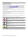
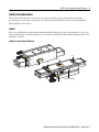
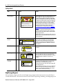

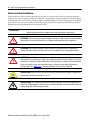
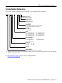
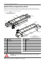
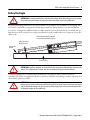
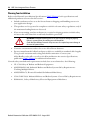
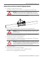

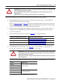
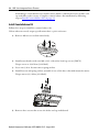
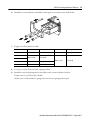

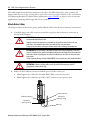
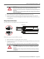
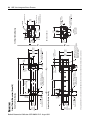

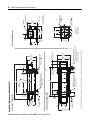
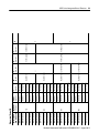
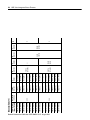
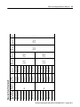
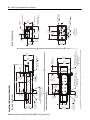
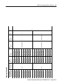
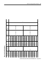
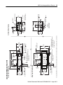
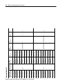
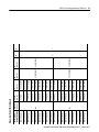
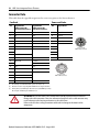
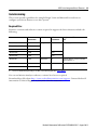
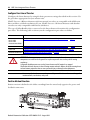
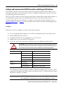


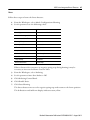
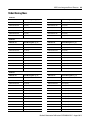


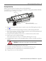

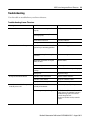
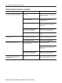
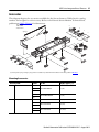
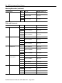
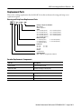
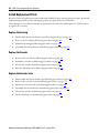

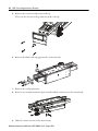

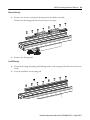
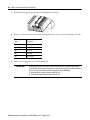

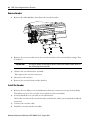
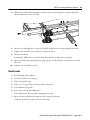
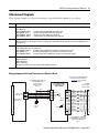
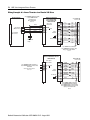
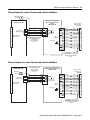
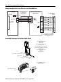
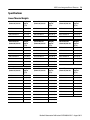
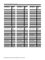
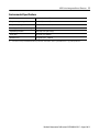
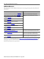


![902 09 05 Rev0 UM Panela Eletrica Super Chef R [780646]](http://vs1.manualzilla.com/store/data/006061438_1-f2c898753805fcda0c66c8333b63035c-150x150.png)