1
SINUMERIK
SINUMERIK 808D ADVANCED
Programming and Operating Manual (Turning)
User Manual
Legal information
Warning notice system
This manual contains notices you have to observe in order to ensure your personal safety, as well as to prevent damage to property. The
notices referring to your personal safety are highlighted in the manual by a safety alert symbol, notices referring only to property damage
have no safety alert symbol. These notices shown below are graded according to the degree of danger.
DANGER
indicates that death or severe personal injury will result if proper precautions are not taken.
WARNING
indicates that death or severe personal injury may result if proper precautions are not taken.
CAUTION
indicates that minor personal injury can result if proper precautions are not taken.
NOTICE
indicates that property damage can result if proper precautions are not taken.
If more than one degree of danger is present, the warning notice representing the highest degree of danger will be used. A notice warning of
injury to persons with a safety alert symbol may also include a warning relating to property damage.
Qualified Personnel
The product/system described in this documentation may be operated only by personnel qualified for the specific task in accordance with
the relevant documentation, in particular its warning notices and safety instructions. Qualified personnel are those who, based on their
training and experience, are capable of identifying risks and avoiding potential hazards when working with these products/systems.
Proper use of Siemens products
Note the following:
WARNING
Siemens products may only be used for the applications described in the catalog and in the relevant technical documentation. If products
and components from other manufacturers are used, these must be recommended or approved by Siemens. Proper transport, storage,
installation, assembly, commissioning, operation and maintenance are required to ensure that the products operate safely and without any
problems. The permissible ambient conditions must be complied with. The information in the relevant documentation must be observed.
© Siemens AG 2012 - 2013. All rights reserved
6FC5398-5DP10-0BA1, 08/2013
1
Preface
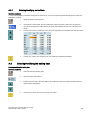
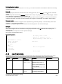
Applicable products
This manual is applicable to the following control system:
Control system
Softvare version
SINUMERIK 808D ADVANCED T (Turning)
V4.6
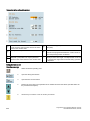
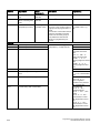
Documentation components and target groups
Component
Recommended target group
User documentation
Programming and Operating Manual (Turning)
Programmers and operators of turning machines
Programming and Operating Manual (Milling)
Programmers and operators of milling machines
Programming and Operating Manual (ISO Turning/Milling)
Programmers and operators of turning/milling machines
Programming and Operating Manual (Manual Machine Plus
Turning)
Programmers and operators of turning machines
Diagnostics Manual
Mechanical and electrical designers, commissioning
engineers, machine operators, and service and
maintenance personnel
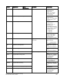
Manufacturer/service documentation
Commissioning Manual
Installation personnel, commissioning engineers, and
service and maintenance personnel
Function Manual
Mechanical and electrical designers, technical professionals
Parameter Manual
Mechanical and electrical designers, technical professionals
PLC Subroutines Manual
Mechanical and electrical designers, technical
professionals, and commissioning engineers
My Documentation Manager (MDM)
Under the following link you will find information to individually compile your documentation based on the Siemens content:
www.siemens.com/mdm
Standard scope
This manual only describes the functionality of the standard version. Extensions or changes made by the machine tool
manufacturer are documented by the machine tool manufacturer.
Technical support
Hotline:
● Global support hotline:
+49 (0)911 895 7222
● Support hotline in China:
+86 4008104288 (china)
Service and Support:
● Chinese Web site:
http://www.siemens.com.cn/808D
● Global Web site:
http://support.automation.siemens.com
EC Declaration of Conformity
The EC Declaration of Conformity for the EMC Directive can be found on the Internet at
http://support.automation.siemens.com
Here, enter the number 15257461 as the search term or contact your local Siemens office.
2
Programming and Operating Manual (Turning)
6FC5398-5DP10-0BA1, 08/2013
Table of contents
Preface................................................................................................................................................................... 2
1
Introduction............................................................................................................................................................. 7
1.1
1.1.1
1.1.2
SINUMERIK 808D ADVANCED operator panels .......................................................................................... 7
Overview ....................................................................................................................................................... 7
Control elements on the PPU........................................................................................................................ 7
1.2
1.2.1
1.2.2
Machine control panels ................................................................................................................................. 9
Overview ....................................................................................................................................................... 9
Control elements on the MCP ..................................................................................................................... 10
1.3
Screen layout .............................................................................................................................................. 12
1.4
Protection levels .......................................................................................................................................... 13
1.5
Setting user interface language .................................................................................................................. 14
2
Turning on, reference point approach .................................................................................................................... 14
3
Setting-up ............................................................................................................................................................. 15
4
5
3.1
Coordinate systems .................................................................................................................................... 15
3.2
3.2.1
3.2.2
3.2.3
3.2.4
3.2.5
3.2.6
3.2.7
Setting up tools ........................................................................................................................................... 17
Creating a new tool ..................................................................................................................................... 17
Activating the tool ........................................................................................................................................ 19
Assigning the handwheel ............................................................................................................................ 19
Activating the spindle .................................................................................................................................. 21
Measuring the tool (manually) ..................................................................................................................... 22
Verifying the tool offset result in "MDA" mode............................................................................................. 25
Entering/modifying the tool wear data ......................................................................................................... 26
3.3
Operating area overview ............................................................................................................................. 27
Part programming ................................................................................................................................................. 28
4.1
Creating a part program .............................................................................................................................. 29
4.2
Editing part programs .................................................................................................................................. 30
4.3
Managing part programs ............................................................................................................................. 32
Automatic machining............................................................................................................................................. 34
5.1
Performing the simulation ........................................................................................................................... 35
5.2
Program control .......................................................................................................................................... 37
5.3
Program test ............................................................................................................................................... 38
5.4
Starting and stopping/interrupting a part program ....................................................................................... 40
5.5
5.5.1
5.5.1.1
5.5.1.2
5.5.1.3
5.5.2
5.5.2.1
5.5.2.2
5.5.2.3
Executing/transferring a part program from external ................................................................................... 40
Executing/transferring through the RS232 interface ................................................................................... 40
Configuring RS232 communication ............................................................................................................. 40
Executing from external (through RS232 interface) .................................................................................... 41
Transferring from external (through RS232 interface) ................................................................................. 42
Executing/transferring through the Ethernet connection ............................................................................. 43
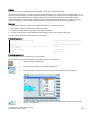
Configuring the Ethernet connection ........................................................................................................... 43
Executing from external (through Ethernet connection) .............................................................................. 46
Transferring from external (through Ethernet connection)........................................................................... 48
5.6
Machining at a specific point ....................................................................................................................... 50
6
Saving system data............................................................................................................................................... 51
7
Data backup ......................................................................................................................................................... 53
8
Programming principles ........................................................................................................................................ 54
8.1
Fundamentals of programming ................................................................................................................... 54
Programming and Operating Manual (Turning)
6FC5398-5DP10-0BA1, 08/2013
3
4
8.1.1
8.1.2
Program names .......................................................................................................................................... 54
Program structure ....................................................................................................................................... 55
8.2
8.2.1
8.2.2
8.2.3
8.2.4
8.2.5
8.2.6
8.2.7
8.2.8
8.2.8.1
8.2.8.2
Positional data ............................................................................................................................................ 55
Programming dimensions ........................................................................................................................... 55
Absolute/incremental dimensioning: G90, G91, AC, IC .............................................................................. 56
Dimensions in metric units and inches: G71, G70, G710, G700 ................................................................. 57
Radius/diameter dimensions: DIAMOF, DIAMON, DIAM90 ....................................................................... 57
Programmable work offset: TRANS, ATRANS ........................................................................................... 58
Programmable scaling factor: SCALE, ASCALE ........................................................................................ 61
Workpiece clamping - settable work offset: G54 to G59, G500, G53, G153 ............................................... 62
Kinematic transformation ............................................................................................................................ 62
Milling on turned parts (TRANSMIT) ........................................................................................................... 62
Cylinder surface transformation (TRACYL) ................................................................................................ 65
8.3
8.3.1
8.3.2
8.3.3
Linear interpolation ..................................................................................................................................... 71
Linear interpolation with rapid traverse: G0 ................................................................................................ 71
Feedrate F .................................................................................................................................................. 72
Linear interpolation with feedrate: G1 ......................................................................................................... 73
8.4
8.4.1
8.4.2
8.4.3
Circular interpolation ................................................................................................................................... 73
Circular interpolation: G2, G3 ..................................................................................................................... 73
Circular interpolation via intermediate point: CIP ........................................................................................ 77
Circle with tangential transition: CT ............................................................................................................ 77
8.5
8.5.1
8.5.2
8.5.3
8.5.4
Thread cutting ............................................................................................................................................. 77
Thread cutting with constant lead: G33 ...................................................................................................... 77
Programmable run-in and run-out path for G33: DITS, DITE...................................................................... 80
Thread cutting with variable lead: G34, G35............................................................................................... 81
Thread interpolation: G331, G332 .............................................................................................................. 82
8.6
8.6.1
8.6.2
Fixed point approach .................................................................................................................................. 83
Fixed point approach: G75 ......................................................................................................................... 83
Reference point approach: G74 .................................................................................................................. 83
8.7
8.7.1
8.7.2
8.7.3
Acceleration control and exact stop/continuous path .................................................................................. 84
Exact stop/continuous-path control mode: G9, G60, G64........................................................................... 84
Acceleration pattern: BRISK, SOFT............................................................................................................ 86
Dwell Time: G4 ........................................................................................................................................... 86
8.8
The third axis .............................................................................................................................................. 87
8.9
8.9.1
8.9.2
8.9.2.1
8.9.2.2
8.9.3
Spindle movements .................................................................................................................................... 87
Spindle speed S, directions of rotation ....................................................................................................... 87
Spindle positioning...................................................................................................................................... 88
Spindle positioning (SPOS, SPOSA, M19, M70, WAITS) ........................................................................... 88
Spindle positioning (SPOS, SPOSA, M19, M70, WAITS): Further information........................................... 93
Gear stages ................................................................................................................................................ 94
8.10
8.10.1
8.10.2
8.10.3
Special turning functions............................................................................................................................. 94
Constant cutting rate: G96, G97 ................................................................................................................. 94
Rounding, chamfer ..................................................................................................................................... 96
Contour definition programming ................................................................................................................. 98
8.11
8.11.1
8.11.2
8.11.3
8.11.4
8.11.5
8.11.6
8.11.7
8.11.8
8.11.9
Tool and tool offset ................................................................................................................................... 100
General information (turning) .................................................................................................................... 100
Tool T (turning) ......................................................................................................................................... 100
Tool offset number D (turning) .................................................................................................................. 101
Selecting the tool radius compensation: G41, G42 ................................................................................... 104
Corner behavior: G450, G451 .................................................................................................................. 105
Tool radius compensation OFF: G40 ........................................................................................................ 106
Special cases of the tool radius compensation ......................................................................................... 107
Example of tool radius compensation (turning)......................................................................................... 107
Special handling of tool compensation (turning) ....................................................................................... 108
8.12
Miscellaneous function M ......................................................................................................................... 109
8.13
H function ................................................................................................................................................. 109
8.14
8.14.1
Arithmetic parameters, LUD and PLC variables ....................................................................................... 110
Arithmetic parameter R ............................................................................................................................. 110
Programming and Operating Manual (Turning)
6FC5398-5DP10-0BA1, 08/2013
9
8.14.2
8.14.3
Local User Data (LUD) .............................................................................................................................. 111
Reading and writing PLC variables ........................................................................................................... 112
8.15
8.15.1
8.15.2
8.15.3
8.15.4
Program jumps .......................................................................................................................................... 113
Unconditional program jumps ................................................................................................................... 113
Conditional program jumps ....................................................................................................................... 113
Program example for jumps ...................................................................................................................... 115
Jump destination for program jumps ......................................................................................................... 115
8.16
8.16.1
8.16.2
8.16.3
Subroutine technique ................................................................................................................................ 116
General information................................................................................................................................... 116
Calling machining cycles (turning)............................................................................................................. 118
Executing external subroutines (EXTCALL) .............................................................................................. 118
8.17
8.17.1
8.17.2
Timers and workpiece counters ................................................................................................................ 119
Runtime timer............................................................................................................................................ 119
Workpiece counter .................................................................................................................................... 120
Cycles ................................................................................................................................................................ 122
9.1
Overview of cycles .................................................................................................................................... 122
9.2
Programming cycles.................................................................................................................................. 122
9.3
Graphical cycle support in the program editor........................................................................................... 123
9.4
9.4.1
9.4.2
9.4.3
9.4.4
9.4.5
9.4.6
9.4.7
9.4.8
9.4.9
9.4.10
9.4.11
9.4.12
Drilling cycles ............................................................................................................................................ 124
General information................................................................................................................................... 124
Requirements ............................................................................................................................................ 125
Drilling, centering - CYCLE81 ................................................................................................................... 127
Drilling, counterboring - CYCLE82 ............................................................................................................ 129
Deep-hole drilling - CYCLE83 ................................................................................................................... 131
Rigid tapping - CYCLE84 .......................................................................................................................... 134
Tapping with compensating chuck - CYCLE840 ....................................................................................... 138
Reaming1 - CYCLE85............................................................................................................................... 142
Boring - CYCLE86..................................................................................................................................... 144
Boring with stop 1- CYCLE87 ................................................................................................................... 146
Drilling with stop 2 - CYCLE88 .................................................................................................................. 148
Reaming 2 - CYCLE89.............................................................................................................................. 149
9.5
9.5.1
9.5.2
9.5.3
9.5.4
9.5.5
9.5.6
9.5.7
9.5.8
Turning cycles ........................................................................................................................................... 150
Requirements ............................................................................................................................................ 150
Cutoff - CYCLE92 ..................................................................................................................................... 152
Groove - CYCLE93 ................................................................................................................................... 154
Undercut (forms E and F to DIN) - CYCLE94 ........................................................................................... 161
Cutting with relief cut - CYCLE95 .............................................................................................................. 164
Thread undercut - CYCLE96..................................................................................................................... 177
Thread chaining - CYCLE98 ..................................................................................................................... 180
Thread cutting - CYCLE99 ........................................................................................................................ 185
9.6
9.6.1
9.6.2
9.6.3
9.6.4
Error messages and error handling ........................................................................................................... 191
General Information .................................................................................................................................. 191
Error handling in the cycles ....................................................................................................................... 191
Overview of cycle alarms .......................................................................................................................... 192
Messages in the cycles ............................................................................................................................. 192
10
Typical turning program ...................................................................................................................................... 192
A
Appendix ............................................................................................................................................................ 198
A.1
Creating a new cutting edge ..................................................................................................................... 198
A.2
A.2.1
Setting up the workpiece ........................................................................................................................... 199
Entering/modifying work offsets ................................................................................................................ 201
A.3
Entering/modifying the setting data ........................................................................................................... 201
A.4
Setting R parameters ................................................................................................................................ 204
A.5
Setting user data ....................................................................................................................................... 204
A.6
A.6.1
Other settings in "JOG" mode ................................................................................................................... 205
Setting the relative coordinate system (REL) ............................................................................................ 206
Programming and Operating Manual (Turning)
6FC5398-5DP10-0BA1, 08/2013
5
6
A.6.2
Setting the JOG data ................................................................................................................................ 207
A.7
The help system ....................................................................................................................................... 207
A.8
Operation wizard....................................................................................................................................... 209
A.9
Editing Chinese characters ....................................................................................................................... 210
A.10
Pocket calculator ...................................................................................................................................... 211
A.11
Calculating contour elements ................................................................................................................... 212
A.12
A.12.1
A.12.2
A.12.3
A.12.4
A.12.5
A.12.6
A.12.7
A.12.8
Free contour programming ....................................................................................................................... 216
Programming a contour ............................................................................................................................ 217
Defining a start point ................................................................................................................................. 218
Programming contour element ................................................................................................................. 219
Parameters for contour elements.............................................................................................................. 221
Undercuts for turning technology .............................................................................................................. 224
Specifying contour elements in polar coordinates..................................................................................... 224
Cycle support............................................................................................................................................ 226
Programming example for turning application .......................................................................................... 227
A.13
Word structure and address ..................................................................................................................... 231
A.14
Character set ............................................................................................................................................ 231
A.15
Block format.............................................................................................................................................. 232
A.16
List of instructions ..................................................................................................................................... 233
Programming and Operating Manual (Turning)
6FC5398-5DP10-0BA1, 08/2013
1
1.1
1.1.1
Introduction
SINUMERIK 808D ADVANCED operator panels
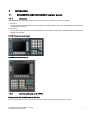
Overview
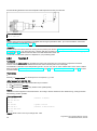
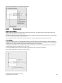
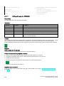
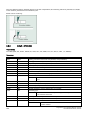
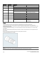
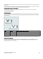
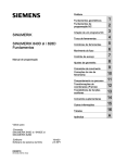
The SINUMERIK 808D ADVANCED PPU (Panel Processing Unit) is available in the following variants:
● PPU161.2
Horizontal panel layout, applicable for the SINUMERIK 808D ADVANCED T (turning) or SINUMERIK 808D ADVANCED
M (milling) control system
● PPU160.2
Vertical panel layout, applicable for the SINUMERIK 808D ADVANCED T (turning) or SINUMERIK 808D ADVANCED M
(milling) control system
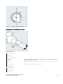
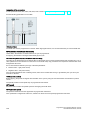
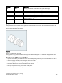
PPU161.2 (horizontal panel layout)
PPU160.2 (vertical panel layout)
1.1.2
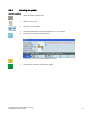
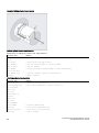
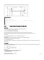
Control elements on the PPU
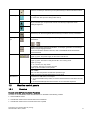
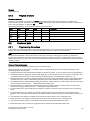
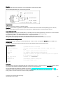
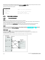
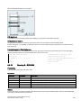
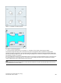
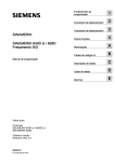
Elements on the PPU (Panel Processing Unit) front
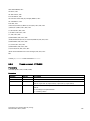
The following illustration uses PPU161.2 as an example to show control elements available on the PPU:
Programming and Operating Manual (Turning)
6FC5398-5DP10-0BA1, 08/2013
7
① Vertical and horizontal softkeys
⑦ On-board wizard key
② Return key
⑧ Help key
③ Menu extension key
⑨ Cursor keys *
④ Alphabetic and numeric keys *
⑩ Operating area keys *
⑤ Control keys *
⑪ USB interface *
⑥ Alarm cancellation key
⑫ Status LEDs *
Calls specific menu functions
Returns to the next higher-level menu
Opens the next lower-level menu or navigate between
the menus of the same level
Cancels alarms and messages that are marked with
this symbol
Provides step-by-step guides on basic commissioning
and operation procedures
Calls help information
* For more information, refer to the table below.
Further information
Alphabetic and
numeric keys
To enter the upper character on an alphabetic/numeric key, keep the following key
pressed:
The icons on the following keys are available only with PPU161.2 and PPU160.2.
The icon on the key is a hint that you can press both <CTRL> and this key as
shortcuts for capturing screens.
The icon on the key is a hint that you can press both <CTRL> and this key as
shortcuts for saving start-up archives.
The icon on the key is a hint that you can press both <CTRL> and this key as
shortcuts for showing pre-defined slides on the screen.
8
Programming and Operating Manual (Turning)
6FC5398-5DP10-0BA1, 08/2013
The icon on the key is a hint that you can press this key to call the calculator function.
● Toggles between entries in the input field
● Enters the "Set-up menu" dialog at NC start-up
Cursor keys
Icons on both keys are available only with PPU161.2 and PPU160.2. The icon on the
key is a hint that you can press both <CTRL> and the key to adjust the screen
backlight brightness.
Control keys
The icon on the key is available only with PPU161.2 and PPU160.2. The icon is a hint
that this key can be used together with another key to function as a key combination.
Operating area
keys
To open the system data management operating area, press the following key
combination:
+
Enables user-defined extension applications, for example, generation of user dialogs
with the EasyXLanguage function.
For more information about this function, refer to SINUMERIK 808D ADVANCED
Function Manual.
Status LEDs
LED "POK"
Lights up green: The power supply for the CNC is switched on.
LED "RDY"
Lights up green: The CNC is ready and the PLC is in running mode.
Lights up orange:
● On: The PLC is in stop mode.
● Flashing: The PLC is in power-up mode.
Lights up red: The CNC is in stop mode.
LED "TEMP"
Unlit: The CNC temperature is within the specified range.
Lights up orange: The CNC temperature is out of range.
USB interface
1.2
1.2.1
Connects to a USB device, for example:
● An external USB memory sticker, to transfer data between the USB sticker and the
CNC
● An external USB keyboard which functions as an external NC keyboard
Machine control panels
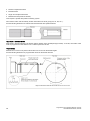
Overview
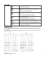
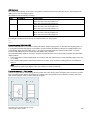
Elements on the MCP (Machine Control Panel) front
The MCP for the SINUMERIK 808D ADVANCED PPU is available in the following variants:
● Horizontal MCP variant
● Vertical MCP variant with a reserved slot for the handwheel
● Vertical MCP variant with an override switch for the spindle
Programming and Operating Manual (Turning)
6FC5398-5DP10-0BA1, 08/2013
9
Horizontal MCP
Vertical MCP with reserved handwheel slot
1.2.2
Vertical MCP with spindle override switch
Control elements on the MCP
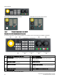
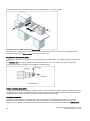
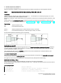
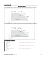
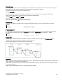
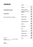
Elements on the MCP (Machine Control Panel) front
The following illustration uses a horizontal MCP as an example to show control elements available on the MCP:
① Reserved hole for emergency stop button
⑦ Axis traversing keys
② Handwheel key
⑧ Spindle override switch
③ Tool number display
⑨
④
⑩ Feedrate override switch
Controls the axis movement with external handwheels
Displays the current tool number
Operating mode keys
⑤ Program control keys
(unavailable for the vertical MCP with reserved
handwheel slot)
Spindle state keys
Traverses the selected axis at the specified feedrate
override
⑪ Keys for program start, stop, and reset
⑥ User-defined keys *
* For more information, refer to the table below.
10
Programming and Operating Manual (Turning)
6FC5398-5DP10-0BA1, 08/2013
Further information
User-defined keys
Pressing this in any operating mode switches on/off the lamp.
LED lit: The lamp is switched on.
LED unlit: The lamp is switched off.
Pressing this key in any operating mode switches on/off the coolant
supply.
LED lit: The coolant supply is switched on.
LED unlit: The coolant supply is switched off.
Pressing this key starts sequential tool changes (active only in "JOG"
mode).
LED lit: The machine starts sequential tool changes
LED unlit: The machine stops sequential tool changes
Pressing this key in any operating mode activates the chuck to
clamp/unclamp the workpiece.
LED lit: Activates the chuck to clamp the workpiece
LED unlit: Activates the chuck to unclamp the workpiece
Pressing this key only when the spindle stops operation.
LED lit: Activates the external chuck to clamp the workpiece inwards
LED unlit: Activates the internal chuck to clamp the workpiece outwards
Pressing this key in any operating mode advances/retracts the tailstock.
LED lit: Advances the tailstock towards the workpiece until it firmly
engages with the end of the workpiece
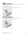
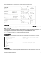
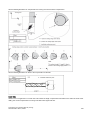
Pre-defined insertion strips
The MCP (machine control panel) package includes two sets (six pieces each) of pre-defined insertion strips. One set is for
the turning variant of the control system and is pre-inserted on the back of the MCP. The other set is for the milling variant of
the control system.
If your control system is of the SINUMERIK 808D ADVANCED milling variant, replace the pre-inserted strips with the millingspecific insertion strips.
Programming and Operating Manual (Turning)
6FC5398-5DP10-0BA1, 08/2013
11
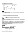
Customized insertion strips
The MCP package also includes an A4-sized blank plastic sheet with detachable strips. You can customize insertion strips if
the pre-defined strips can not meet your needs.
In the \examples\MCP folder of the Toolbox DVD for the SINUMERIK 808D ADVANCED, there is a symbol library file and an
insertion strip template file. To make customized insertion strips, follow the steps below:
1. Copy the desired symbols from the symbol library file to the desired locations in the insertion strip template.
2. Print the template to the A4-sized blank plastic sheet.
3. Detach the insertion strips from the blank plastic sheet.
4. Pull out the pre-inserted strips from the MCP.
5. Insert the customized strips on the back of the MCP.
Note
This manual assumes an 808D standard machine control panel (MCP). Should you use a different MCP, the operation
may be other than described herein.
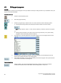
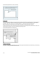
1.3
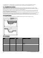
Screen layout
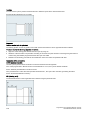
Alarms and messages
Displays active alarms with alarm text
The alarm number is displayed in white lettering on a red background. The
associated alarm text is shown in red lettering. An arrow indicates that
several alarms are active. The number to the right of the arrow indicates
the total number of active alarms. When more than one alarm is active, the
display scrolls through the alarms in sequence. An acknowledgement
symbol indicates the alarm cancel criterion.
Displays messages from NC programs
Messages from NC programs do not have numbers and appear in green
lettering.
12
Programming and Operating Manual (Turning)
6FC5398-5DP10-0BA1, 08/2013
1.4
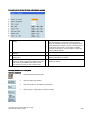
Protection levels
Overview
The SINUMERIK 808D ADVANCED provides a concept of protection levels for enabling data areas. Different protection
levels control different access rights.
The control system delivered by SIEMENS is set by default to the lowest protection level 7 (without password). If the
password is no longer known, the control system must be reinitialized with the default machine/drive data. All passwords are
then reset to default passwords for this software release.
Note
Before you boot the control system with default machine/drive data, make sure that you have backed up your machine/drive
data; otherwise, all data are lost after rebooting with default machine/drive data.
Protection level
Locked by
Area
0
1
2
Siemens password
Manufacturer password
Reserved
Siemens, reserved
Machine manufacturers
3-6
End user password
(Default password: "CUSTOMER")
No password
End users
7
End users
Protection level 1
Protection level 1 requires a manufacturer password. With this password entry, you can perform the following operations:
● Entering or changing part of the machine data and drive data
● Conducting NC and drive commissioning
Protection level 3-6
Protection level 3-6 requires an end user password. With this password entry, you can perform the following operations:
● Entering or changing part of the machine data and drive data
● Editing programs
● Setting offset values
● Measuring tools
Protection level 7
Protection level 7 is set automatically if no password is set and no protection level interface signal is set. The protection level
7 can be set from the PLC user program by setting the bits in the user interface.
In the menus listed below the input and modification of data depends on the set protection level:
● Tool offsets
● Work offsets
● Setting data
● RS232 settings
● Program creation/program correction
The number of machine data and drive data which can be read or modified depends on the protection level. You can set the
protection level for these function areas with the display machine data (USER_CLASS...).
Setting password
You can set the desired password through the following operating area:
+
→
Programming and Operating Manual (Turning)
6FC5398-5DP10-0BA1, 08/2013
13
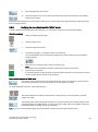
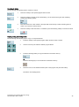
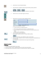
1.5
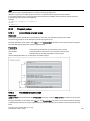
Setting user interface language
Operating sequence
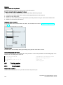
1.
Select the desired operating area.
2.
Press this softkey to open the user interface language selection window.
3.
Use the cursor keys to select the desired language.
4.
Press this softkey to confirm your selection.
+
Note:
The HMI (Human Machine Interface) is automatically restarted when a new language is
selected.
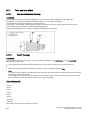
2
Turning on, reference point approach
Note
When turning on the CNC and the machine, also observe the machine tool manufacturer's documentation, since turning-on
and reference point approach are machine-dependent functions.
Operating sequence
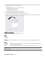
1.
Switch on the power supply for the control system and the machine.
2.
Release all emergency stop buttons on the machine.
By default, the control system is in the "REF POINT" window after booting.
shown next to the axis identifier indicates that the axis is not yet referenced. If an axis is
The symbol
not referenced, the symbol is always visible in the current (machining) operating area.
14
Programming and Operating Manual (Turning)
6FC5398-5DP10-0BA1, 08/2013
3.
Press the corresponding axis traversing keys on the MCP to traverse each axis to the reference point.
If the axis is referenced, a symbol (
POINT" window.
) appears next to the axis identifier and is visible only in the "REF
Note that axis traversing directions and axis key functions are defined by the machine manufacturer.
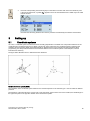
3
3.1
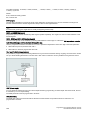
Setting-up
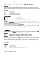
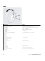
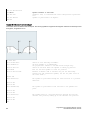
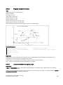
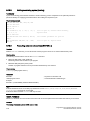
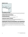
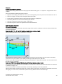
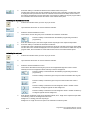
Coordinate systems
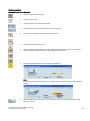
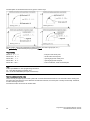
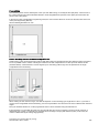
As a rule, a coordinate system is formed from three mutually perpendicular coordinate axes. The positive directions of the
coordinate axes are defined using the so-called "3-finger rule" of the right hand. The coordinate system is related to the
workpiece and programming takes place independently of whether the tool or the workpiece is being traversed. When
programming, it is always assumed that the tool traverses relative to the coordinate system of the workpiece, which is
intended to be stationary.
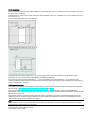
The figure below illustrates how to determine the axis directions.
Machine coordinate system (MCS)
The orientation of the coordinate system relative to the machine depends on the machine type. It can be rotated in different
positions.
The directions of the axes follow the "3-finger rule" of the right hand. Seen from the front of the machine, the middle finger of
the right hand points in the opposite direction to the infeed of the spindle.
Programming and Operating Manual (Turning)
6FC5398-5DP10-0BA1, 08/2013
15
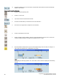
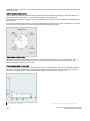
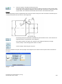
The figure below shows an example of the machine coordinate system of a turning machine.
The origin of this coordinate system is the machine zero.
This point is only a reference point which is defined by the machine manufacturer. It does not have to be approachable.
The traversing range of the machine axes can be in the negative range.
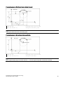
Workpiece coordinate system (WCS)
To describe the geometry of a workpiece in the workpiece program, a right-handed, right-angled coordinate system is also
used.
The workpiece zero can be freely selected by the programmer in the Z axis. In the X axis, it lies in the turning center.
The figure below shows an example of the workpiece coordinate system.
Relative coordinate system (REL)
In addition to the machine and workpiece coordinate systems, the control system provides a relative coordinate system. This
coordinate system is used to set reference points that can be freely selected and have no influence on the active workpiece
coordinate system. All axis movements are displayed relative to these reference points.
Clamping the workpiece
For machining, the workpiece is clamped on the machine. The workpiece must be aligned such that the axes of the
workpiece coordinate system run in parallel with those of the machine. Any resulting offset of the machine zero with
reference to the workpiece zero is determined along the Z axis and entered in a data area intended for the settable work
16
Programming and Operating Manual (Turning)
6FC5398-5DP10-0BA1, 08/2013
offset. In the NC program, this offset is activated during program execution, for example, using a programmed G54
command.
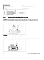
The figure below shows an example of the workpiece clamped on the machine.
Current workpiece coordinate system
The programmed work offset TRANS (Page 58) can be used to generate an offset with reference to the workpiece
coordinate system, resulting in the current workpiece coordinate system.
3.2
3.2.1
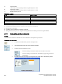
Setting up tools
Creating a new tool
Note
The control system supports a maximum of 64 tools or 128 cutting edges.
Operating sequence
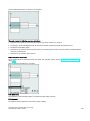
1.
Select the desired operating area.
2.
Open the tool list window.
3.
Open the lower-level menu for tool type selection.
4.
Select a desired tool type with the corresponding softkey.
Programming and Operating Manual (Turning)
6FC5398-5DP10-0BA1, 08/2013
17
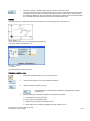
5.
Enter the tool number (value range: 1 to 31999; preferentially enter a value less than 100) and
select the corresponding tool edge position code according to the actual tool point direction in the
following windows:
● Available edge positions for turning tool and grooving tool: 1, 2, 3 and 4 (taking new turning tool
as an example)
● Available edge positions for drilling tool, tapping tool and milling tool: 5, 6, 7 and 8 (taking new
milling tool as an example)
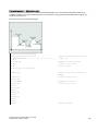
6.
7.
18
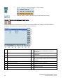
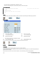
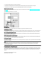
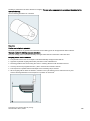
Use this softkey to confirm your settings. The window below shows the information of the new tool
created.
①
②
Tool type
Tool radius
Tool number
⑤
⑥
③
④
Cutting edge number
⑦
Cutting edge direction
Tip width of the cutting edge, which is
only active for the grooving tool
Tool length in the X and Z axes
Enter the tool radius data or tool tip width as desired and confirm your settings.
Programming and Operating Manual (Turning)
6FC5398-5DP10-0BA1, 08/2013
3.2.2
Activating the tool
Operating sequence
3.2.3
1.
Select the desired operating area.
2.
Switch to "JOG" mode.
3.
Open the "T, S, M" window.
4.
Enter the desired tool number (for example, 1) in the "T, S, M" window.
5.
Use this key or move the cursor to confirm your entries.
6.
Press this key on the MCP to activate the tool.
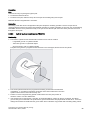
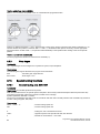
Assigning the handwheel
Method 1: Assigning through the MCP
1.
Select the desired operating area.
2.
Press this key on the MCP to control the axis movement with external handwheels.
3.
Press the desired axis traversing key with the handwheel icon. The handwheel is assigned.
Method 2: Assigning through the PPU
1.
Select the desired operating area.
2.
Open the machine data window.
+
Programming and Operating Manual (Turning)
6FC5398-5DP10-0BA1, 08/2013
19
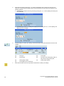
3.
Press this softkey to open the basic machine data list.
4.
Use the cursor keys or the following softkey to search for the general machine data "14512
USER_DATA_HEX[16]".
5.
Select "Bit7" by using the following key and cursor keys:
Press the following softkey to confirm your input.
6.
Press this vertical softkey to activate the value change. Note that the control system restarts to
accept the new value.
7.
After the control system has booted, select the desired operating area.
8.
Press this key on the MCP.
9.
Press this vertical softkey to open the handwheel assignment window.
10.
Select the desired handwheel number with the cursor left/right key.
11.
Press the relevant axis softkey for handwheel assignment or deselection.
The symbol "☑" that appears in the window indicates a handwheel has been assigned to the
specific axis.
12.
Select the required override increment. The selected axis can now be moved with the
handwheel.
The override increment is 0.001 mm.
The override increment is 0.010 mm.
The override increment is 0.100 mm.
20
Programming and Operating Manual (Turning)
6FC5398-5DP10-0BA1, 08/2013
3.2.4
Activating the spindle
Operating sequence
1.
Select the desired operating area.
2.
Switch to "JOG" mode.
3.
Open the "T, S, M" window.
4.
Enter the desired value for the spindle speed in the "T, S, M" window.
5.
Press this key to select the spindle direction.
6.
Use this key or move the cursor to confirm your entries.
7.
Press this key on the MCP to activate the spindle.
Programming and Operating Manual (Turning)
6FC5398-5DP10-0BA1, 08/2013
21
3.2.5
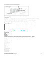
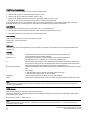
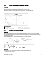
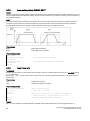
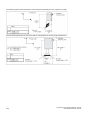
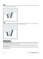
Measuring the tool (manually)
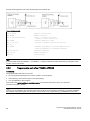
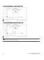
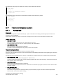
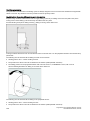
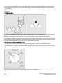
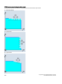
Overview
The geometries of the machining tool must be taken into consideration when you execute a part program. These are stored
as tool offset data in the tool list. Each time the tool is called, the control considers the tool offset data.
You can determine the tool offset data, including the length, radius and diameter by either measuring the tool or entering the
values in the tool list (see Section "Creating a new tool (Page 17)" for more information).
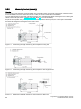
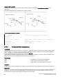
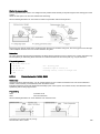
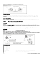
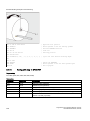
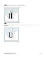
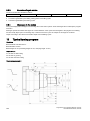
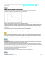
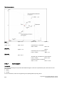
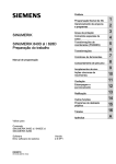
As per the actual position of the point F (the machine coordinate) and the reference point, the control system can calculate
the offset value assigned to the lengths for the X and Z axes.
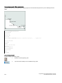
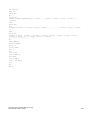
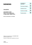
Figure 3-1
Determining the length offsets using the example of a turning tool
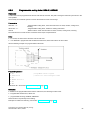
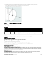
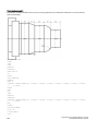
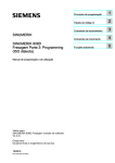
Figure 3-2
Determining the length offsets using the example of a drill: Length 1/Z axis
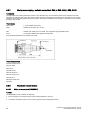
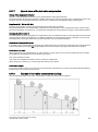
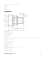
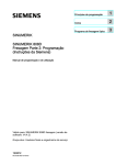
Figure 3-3
Determining the length offsets using the example of a milling tool
22
Programming and Operating Manual (Turning)
6FC5398-5DP10-0BA1, 08/2013
Operating sequence
Measuring the tool in the X direction
1.
Select the desired operating area.
2.
Switch to "JOG" mode.
3.
Open the manual tool measurement window.
4.
Press this vertical softkey to measure the tool in the X direction.
5.
Move the tool to approach the workpiece in the X direction.
6.
Switch to handwheel control mode.
7.
Select a suitable override feedrate, and then use the handwheel to move the tool to scratch the
required workpiece edge (or the edge of the setting block, if it is used).
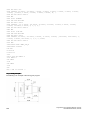
8.
Enter the workpiece diameter in the "Ø" field (for example, 50).
...
Note:
For a milling tool with edge position 5 or 7, the radius of the tool itself is displayed in the following
window:
9.
Save the length value in the X axis. The tool diameter, radius, and cutting edge position are all
taken in to account.
Programming and Operating Manual (Turning)
6FC5398-5DP10-0BA1, 08/2013
23
10.
Press this softkey and you can see that the compensation data values have been automatically
added to the tool data.
Measuring the tool in the Z direction
1.
Select the desired operating area.
2.
Switch to "JOG" mode.
3.
Open the manual tool measurement window.
4.
Press this vertical softkey to measure the tool in the Z direction.
5.
Move the tool to approach the workpiece in the Z direction.
6.
Switch to handwheel control mode.
7.
Select a suitable override feedrate, and then use the handwheel to move the tool to scratch the
required workpiece edge (or the edge of the setting block, if it is used).
8.
Enter the distance between the tool tip and the workpiece edge in the "Z0" field, for example, "0".
(This value is the thickness of a setting block if it is used.)
...
Note:
For a milling tool with edge position 6 or 8, the radius of the tool itself is displayed in the following
window:
24
Programming and Operating Manual (Turning)
6FC5398-5DP10-0BA1, 08/2013
9.
Save the length value in the Z axis.
10.
Press this softkey and you can see that the compensation data values have been automatically
added to the tool data.
Repeat the above operations for other tools and make sure you measure all the tools before machining, which also eases
the tool changing process.
3.2.6
Verifying the tool offset result in "MDA" mode
In order to ensure the machine safety and correctness, you must test the results of the tool offset appropriately.
Operating sequence
1.
Select the desired operating area.
2.
Switch to "MDA" mode.
3.
Press this softkey on the PPU.
4.
Enter the test program, for example: G500 T1 D1 G00 X0 Z5.
You can alternatively load an existing part program from a system directory using the following
softkey if desired:
5.
Press this key to ensure the "ROV" function is active (lit up).
Note:
The "ROV" function activates the feedrate override switch under the G00 function.
6.
Press this key on the MCP.
Increase the feedrate override gradually to avoid accidents caused by an axis moving too fast and
observe whether the axis moves to the set position.
Further softkey functions in "MDA" mode
This window displays important G functions whereby each G function is assigned to a group and has a
fixed position in the window. To close the window, press this softkey once again.
To display additional G functions, use the following keys:
This window displays the auxiliary and M functions currently active. To close the window, press this
softkey once again.
This softkey opens the file saving window where you can specify a name and a storage medium for the
program displayed in the MDA window. To save your program, either enter a new program name in the
input field or select an existing program for overwriting.
Note: If you do not save with this softkey, the program edited in "MDA" mode is actually a temporary file.
Programming and Operating Manual (Turning)
6FC5398-5DP10-0BA1, 08/2013
25
Pressing this softkey deletes all the blocks displayed in the MDA window.
This softkey opens a window where you can select an existing program file from a system directory to
load into the MDA buffer.
For the explanation of other softkeys in this mode, refer to Section "Other settings in "JOG" mode (Page 205)".
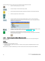
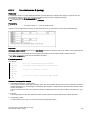
3.2.7
Entering/modifying the tool wear data
Note
You must distinguish the direction of tool wear compensation clearly.
Operating sequence
1.
Select the desired operating area.
2.
Open the tool wear window.
3.
Use the cursor keys to select the required tools and their edges.
4.
Enter the tool length wear parameter of axis X and axis Z as well as the tool radius wear parameter.
Positive value: The tool moves away from the workpiece.
Negative value: The tool moves closer to the workpiece.
5.
26
Press this key or move the cursor to activate the compensation.
Programming and Operating Manual (Turning)
6FC5398-5DP10-0BA1, 08/2013
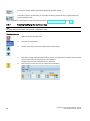
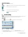
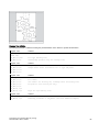
3.3
Operating area overview
When working with the CNC, you need to set up the machine and the tools, etc. as follows:
● Create the tools and cutting edges.
● Enter/modify the tool and work offsets.
● Enter the setting data.
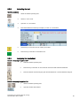
Softkey functions
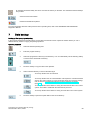
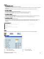
Pressing this key on the PPU allows you to open the following window:
①
Displays and modifies the tool offsets
⑦
②
Displays and modifies the tool wear data
⑧
③
Displays and modifies the work offsets
④
Displays and modifies the R variables
⑩
Removes the currently selected tool from the tool list
⑤
Configures and displays lists of setting data
⑪
Searches for your desired tool with the tool number
⑥
Displays the defined user data
Programming and Operating Manual (Turning)
6FC5398-5DP10-0BA1, 08/2013
⑨
Measures the tool manually
Creates a new tool
For more information, see Section "Creating a new
tool (Page 17)".
Opens a lower-level menu for cutting edge settings
For more information, see Section "Creating a new
cutting edge (Page 198)".
27
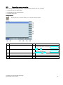
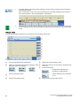
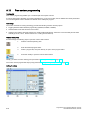
4
Part programming
The SINUMERIK 808D ADVANCED control system can store a maximum of 300 part programs which include those created
by the control system for certain functions such as MM+, TSM, and so on.
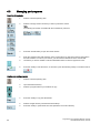
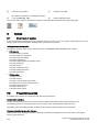
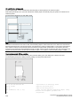
Softkey functions
Pressing this key on the PPU allows you to open the following window:
①
Stores the NC programs for subsequent operations
⑨
Executes the selected file. No editing is allowed in the
execution process
②
Manages and transfers the manufacturer cycles
⑩
Creates new files or directories
③
Reads in/out files via the USB drive and executes the
program from the external storage media
⑪
Searches for files
④
Reads in/out files via the RS232 interface and
executes the program from an external PC/PG
⑫
Selects all files for the subsequent operations
⑤
Reads in/out files via the Ethernet interface and
executes the program from an external PC/PG
⑬
Copies the selected file(s) to the clipboard
⑥
Backs up manufacturer files
⑭
Pastes the selected file(s) from the clipboard to the
current directory
⑦
Backs up user files
⑮
Restores the deleted file(s)
⑧
Shows the recently accessed files
⑯
Opens the second-level softkeys, for example:
28
Programming and Operating Manual (Turning)
6FC5398-5DP10-0BA1, 08/2013
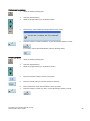
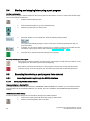
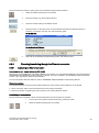
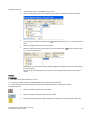
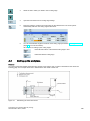
4.1
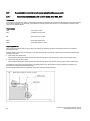
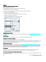
Creating a part program
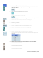
Operating sequence
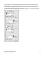
To create a part program, follow these steps:
1.
Select the desired operating area.
2.
Enter the folder for the new program to be created.
3.
If you desire to directly create a new program file, press this softkey and proceed to Step 4.
Note:
If you desire to create a new program directory first, press this softkey and proceed as follows
before you go to Step 4:
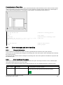
①
Press this softkey to activate the window for creating a new directory.
②
③
Enter a desired name for the new directory.
④
Select the new directory with the cursor keys.
⑤
Press this key on the PPU to open the directory.
Press this softkey to confirm your entry.
4.
Press this softkey to activate the window for creating a new program.
5.
Enter the name of the new program. If you desire to create a main program, it is unnecessary to
enter the file extension ".MPF". If you desire to create a subprogram, you must enter the file
extension ".SPF". The character length of a program name is limited to 24 English characters or 12
Chinese characters. It is recommended that you do not use any special characters in the program
name.
6.
Press this softkey to confirm your entry. The part program editor window opens. Enter the blocks in
the window, which are saved automatically.
Programming and Operating Manual (Turning)
6FC5398-5DP10-0BA1, 08/2013
29
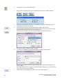
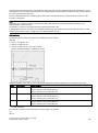
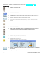
4.2
Editing part programs
Overview
A part program or sections of a part program can only be edited if currently not being executed. Any modifications to the part
program are stored immediately.
Operating sequence
1.
Select the desired operating area.
2.
Enter the program directory.
3.
Select the program file you desire to edit. You can also search for a file or directory by either:
● Pressing the following softkey and specifying the desired criteria in the search dialog:
Note: the file extension ".MPF" or ".SPF" must be entered if you desire to search for a program
file.
Or:
● Entering the first character on the main screen of the program directory. The system directly
navigates to the first file starting with that character.
4.
Press this key to open the program file. The system switches over to the program editor window.
5.
Edit the blocks in the window as required. Any program changes are automatically stored. See
below for the detailed description of the editing options.
6.
After finishing the editing, you can press this softkey to execute the program. The system switches
to the "AUTO" mode in the machining area.
Renumbering blocks
With this softkey, the system automatically assigns block numbers to each block. The block
numbers are inserted in front of each block in the ascending order in a step of 10.
30
Programming and Operating Manual (Turning)
6FC5398-5DP10-0BA1, 08/2013
Searching for blocks
Proceed through the following steps to search for a block:
1.
Press this softkey in the opened program editor window.
2.
Press this softkey to search via text. Alternatively, you can search with a given line number by
pressing the following softkey:
2.
Enter the search text or line number in the input field. Press this key to select a starting point for
search if you choose to search via text.
4.
Press this softkey to start the search, or otherwise, press the following softkey to cancel the search:
Copying, cutting, and pasting blocks
Proceed through the following steps to copy, cut, and paste blocks:
1.
Press this softkey in the opened program editor window to insert a marker.
2
Use the cursor keys to select the desired program blocks.
3.
Press the following softkey to copy the selection to the buffer memory:
Or
Press the following key to cut the selection to the buffer memory:
4.
Place the cursor on the desired insertion point in the program and press this softkey.
The data is successfully pasted.
Programming and Operating Manual (Turning)
6FC5398-5DP10-0BA1, 08/2013
31
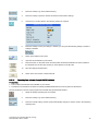
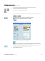
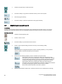
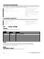
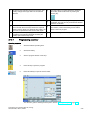
4.3
Managing part programs
Searching for programs
1.
Select the desired operating area.
2.
Select the storage medium in which you wish to perform the search.
Note:
The following two folders are visible with the manufacturer password:
3.
Press this vertical softkey to open the search window.
4.
Enter the complete name with extension of the program file to be searched in the first input field in
the search window. To narrow your search, you can enter the desired text in the second field.
5.
Use this key to choose whether to include subordinate folders or observe upper/lower case.
6.
Press this softkey to start the search, or otherwise, press the following softkey to cancel the search:
Copying and pasting programs
32
1.
Select the desired operating area.
2.
Open the desired directory.
3.
Select the program file that you would like to copy.
4.
Press this softkey to copy the selected file.
5.
Select the target directory with the horizontal softkeys.
6.
Press this softkey to paste the file from the clipboard to the current directory.
Programming and Operating Manual (Turning)
6FC5398-5DP10-0BA1, 08/2013
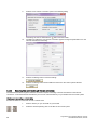
Deleting/restoring programs
1.
Select the desired operating area.
2.
Open the desired directory.
3.
Select the program file that you would like to delete.
4.
Press this key, and the following message appears on the screen:
5.
Press this softkey to confirm the deletion, or press the following softkey to cancel:
If you want to restore the last deleted file, press the following softkey:
Renaming programs
1.
Select the desired operating area.
2.
Open the desired directory.
3.
Select the program file that you would like to rename.
4.
Press the extension softkey to access more options.
5.
Press this vertical softkey to open the window for renaming.
6.
Enter a desired new name with the extension in the input field.
7.
Press this softkey to confirm your entry, or press the following softkey to cancel:
Programming and Operating Manual (Turning)
6FC5398-5DP10-0BA1, 08/2013
33
Viewing and executing recent programs
1.
Select the desired operating area.
2.
Press this softkey to open the list of recent files. Note that even the deleted files are also displayed
in the list.
3.
Select the program file that you would like to execute.
4.
Press this vertical softkey to start executing the selected program.
To clear the current file list, press the following softkey:
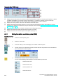
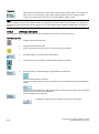
5
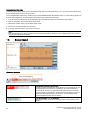
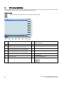
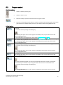
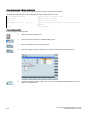
Automatic machining
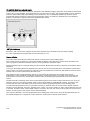
Overview
The machine must have been set up for "AUTO" mode according to the specifications of the machine manufacturer. You can
perform such operations as program start, stop, control, block search, and real-time simulation, etc.
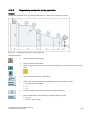
Softkey functions
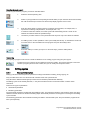
Pressing
①
②
34
key on the PPU and then
key on the MCP allows you to open the following window:
Zooms in the actual value window
Performs the program test, dry run, conditional stop,
block skipping, and auxiliary function lock
⑥
⑦
Displays important G functions
Displays currently active auxiliary and M functions
Programming and Operating Manual (Turning)
6FC5398-5DP10-0BA1, 08/2013
③
Finds the desired block location
⑧
Displays the axis feedrate in the selected coordinate
system
④
Activates the simulation function
⑨
Displays the information of part machining time (part
timer) and part counter
⑤
Corrects a wrong program block. Any changes will be
stored immediately.
⑩
Switches over the coordinate system in the actual value
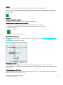
window
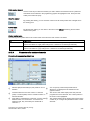
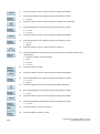
Parameters
① Displays the axes that exist in the machine coordinate
system (MCS), workpiece coordinate system (WCS), or
relative coordinate system(REL).
③ Displays the remaining distance for the axes to
traverse.
② Displays the current position of the axes in the selected ④ Displays seven subsequent blocks of the currently
coordinate system.
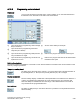
5.1
active part program. The display of one block is limited
to the width of the window.
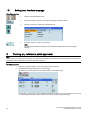
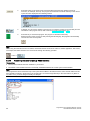
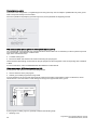
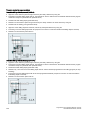
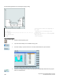
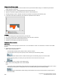
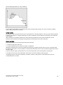
Performing the simulation
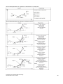
Functionality
By using the broken-line graphics, the programmed tool path can be traced. Before the automatic machining, you need to
perform the simulation to check whether the tool moves in the right way.
Operating sequence
1.
Select the desired operating area.
2.
Select a part program for simulation.
3.
Press this key to open the program.
4.
Switch to "AUTO" mode.
Programming and Operating Manual (Turning)
6FC5398-5DP10-0BA1, 08/2013
35
5.
Press this softkey to open the program simulation window, and the program control mode PRT is
automatically activated.
If the control system is not in the correct operating mode, a message will appear at the bottom of
the screen as follows. If this message appears, repeat Step 4.
6.
Press this key to start the standard simulation for the execution of the selected part program. Note
that the simulation function can be executed only when the control system is in "AUTO" operating
mode!
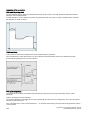
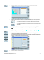
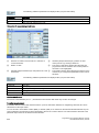
Softkey functions
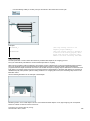
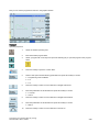
The following describes the functions of the softkeys on the simulation main screen.
①
②
⑤
Enters the lower-level menu for block displaying. Three ⑥
Shows the simulation track automatically.
Deletes the current simulation track.
displaying options are available:
Makes the cross hair move in large or small steps with
the cursor.
⑦
Shows more options:
Enables the material removal
simulation of a defined blank
③
Zooms in the whole screen.
④
Zooms out the whole screen.
36
Selects whether to show the blocks
or not
⑧
Returns to the program editor window.
Programming and Operating Manual (Turning)
6FC5398-5DP10-0BA1, 08/2013
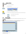
5.2
Program control
Operating sequence
1.
Select the desired operating area.
2.
Switch to "AUTO" mode.
3.
Press this softkey to open the lower-level menu for program control.
4.
Press the corresponding vertical softkey to activate or deactivate the desired program control option
(see table below for detailed softkey functions). The softkeys selected are highlighted in blue.
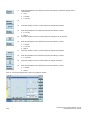
Softkey functions
Disables the output of setpoints to axes and spindles. The setpoint display "simulates" the traverse
movements.
It functions the same as pressing the following key:
After activating this option, the icon "PRT" appears immediately in the program status bar and this
softkey is highlighted in blue.
For more information of the program test, refer to Section "Program test (Page 38)".
All traversing motions are performed with the feedrate setpoint specified via the "Dry run feed" setting
data. Instead of the programmed motion commands, the dry run feed rate is effective.
After activating this option, the icon "DRY" appears immediately in the program status bar and this
softkey is highlighted in blue.
Stops processing of the program at every block in which miscellaneous function M01 is programmed.
It functions the same as pressing the following key:
After activating this option, the icon "M01" appears immediately in the program status bar and this
softkey is highlighted in blue.
Skips program blocks that are identified with a slash in front of the block number (e.g. "/N100").
After activating this option, the icon "SKP" appears immediately in the program status bar and this
softkey is highlighted in blue.
Available only in the following state:
Each block is decoded separately, and a stop is performed at each block. However, for the thread
blocks without dry run feedrate, a stop is only performed at the end of the current thread block.
It functions the same as pressing the following key:
After activating this option, the icon "SBL" appears immediately in the program status bar and this
softkey is highlighted in blue.
Programming and Operating Manual (Turning)
6FC5398-5DP10-0BA1, 08/2013
37
The feedrate override switch also acts on the rapid traverse override.
It functions the same as pressing the following key:
After activating this option, the icon "ROV" appears immediately in the program status bar and this
softkey is highlighted in blue.
Performs program test before real machining by checking the axis movement on the machine. It
disables the output of setpoints to spindles and suppresses all auxiliary functions.
After activating this option, the icon "AFL" appears immediately in the program status bar and this
softkey is highlighted in blue.
Note that the display is toggled between "AFL" and "PRT" by pressing the corresponding softkey. Only
one of these two functions can be active at the same time.
5.3
Program test
You can test a part program using three different methods before machining pieces.
Testing the program with dry run
With dry run, all programmed motion commands are replaced by a defined dry run feedrate (refer to Section
"Entering/modifying the setting data (Page 201)"). Before executing the dry run, first remove the workpiece from the
machine.
Proceed as follows to test a part program with dry run.
1.
Select the desired operating area.
2.
Switch to "AUTO" mode.
3.
Press this softkey to open the lower-level menu for program control.
4.
Press this vertical softkey to activate the feedrate settings for the dry run.
5.
Press this key on the MCP to close the door in the machine (if you do not use this function, just
close the door in the machine manually).
6.
Make sure the feedrate override is 0%. Check that correct tool is in spindle before continuing.
7.
Press this key on the MCP to run the program.
8.
Turn the feedrate override switch slowly to the desired value.
9.
Press this key to stop the program test.
Testing the program with PRT
In PRT mode, you can simply check the correctness of your part program with no axis or spindle movement.
Proceed as follows to test a part program in PRT mode.
1.
38
Select the desired operating area.
Programming and Operating Manual (Turning)
6FC5398-5DP10-0BA1, 08/2013
2.
Switch to "AUTO" mode.
3.
Press this key on the MCP to activate the PRT mode.
Alternatively, you can also activate PRT through the following softkey operations:
→
4.
Press this key on the MCP to run the program. The setpoint display "simulates" the traverse
movements.
5.
Press this key to stop the program test.
Testing the program with AFL
The AFL (auxiliary function lock) function disables the spindle and suppresses all auxiliary functions.
Auxiliary function
Address
Tool selection
T
Tool offset
D, DL
Feedrate
F
Spindle speed
S
M functions
M
H functions
H
When the AFL is active, you can test the part program by checking the axis movement. Only one of the functions PRT and
AFL can be active at the same time. Before starting the program test, first remove the workpiece from the machine.
Proceed as follows to test a part program in AFL mode.
1.
Select the desired operating area.
2.
Switch to "AUTO" mode.
3.
Press this softkey to open the lower-level menu for program control.
4.
Press this vertical softkey to activate the AFL function.
5.
Press this key on the MCP to close the door in the machine (if you do not use this function, just
close the door in the machine manually). Make sure the feedrate override is 0%.
6.
Press this key on the MCP to run the program.
7.
Turn the feedrate override switch slowly to the desired value.
8.
Press this key to stop the program test.
Programming and Operating Manual (Turning)
6FC5398-5DP10-0BA1, 08/2013
39
5.4
Starting and stopping/interrupting a part program
Starting a part program
Before starting a program, make sure that both the control system and the machine are set up. Observe the relevant safety
notes of the machine manufacturer.
1.
Select the desired operating area.
2.
Press a horizontal softkey to go to the desired directory.
3.
Select the program that you desire to start.
4.
Press this softkey. For some directories, press the following softkey instead:
The system automatically changes to "AUTO" mode in the machining operating area after you
press the softkey.
5.
If desired, you can use this softkey to specify how you want the program to be executed (for more
information of the program control, refer to Section "Program control (Page 37)").
6.
Press this key to start the automatic machining of the program.
Stopping/interrupting a part program
Press this key to stop the execution of a part program. The program currently running is aborted. On the
next program start, the machining starts from the beginning.
Press this key to interrupt the execution of a part program. The axes stop running while the spindle
continues running. On the next program start, the machining is resumed from the interruption point.
5.5
5.5.1
5.5.1.1
Executing/transferring a part program from external
Executing/transferring through the RS232 interface
Configuring RS232 communication
Communication tool - SinuComPCIN
To enable the RS232 communication between a SINUMERIK 808D ADVANCED and a PC/PG, you must have the RS232
communication tool SinuComPCIN installed on your PC/PG. This tool is available in the SINUMERIK 808D ADVANCED
Toolbox.
RS232 communication settings
Proceed as follows to configure the communication settings for the RS232 interface:
40
1.
Connect the control system with the PC/PG using an RS232 cable.
2.
Select the desired operating area on the PPU.
Programming and Operating Manual (Turning)
6FC5398-5DP10-0BA1, 08/2013
5.5.1.2
3.
Press this softkey to go to the RS232 directory.
4.
Press this softkey to open the window for RS232 communication settings.
5.
Use this key to set the values in the following window as required:
6.
Press this softkey to save your settings. If desired, you can press the following softkey to reset the
settings to defaults:
7.
Return to the RS232 main screen.
8.
Open the SinuComPCIN on your PC/PG.
9.
Press this button on the main screen and then select the desired baudrate from the list. Note that
this baudrate must be the same as that you have selected on the NC side.
10.
Save the settings with this button.
11.
Return to the main screen of SinuComPCIN.
Executing from external (through RS232 interface)
Prerequisites:
● The tool SinuComPCIN has been installed on your PC/PG.
● The RS232 communication has been successfully established between the control system and the PC/PG.
Proceed as follows to execute a part program from external through the RS232 interface:
1.
Select the desired operating area on the PPU.
2.
Press this softkey to go to the RS232 directory.
3.
Press this vertical softkey, and the system automatically changes to "AUTO" mode in the machining
operating area.
Programming and Operating Manual (Turning)
6FC5398-5DP10-0BA1, 08/2013
41
4.
Press this button on the main screen of SinuComPCIN and select the desired program for
execution, for example, Test.mpf. The program is transferred to the buffer memory on the control
system and then displayed in the following window:
5.
If desired, you can use this softkey to specify how you want the program to be executed (for more
information of the program control, refer to Section "Program control (Page 37)") .
6.
Press this key to execute the program. The program is reloaded continuously.
Either at the end of the program or after pressing the following key, the program is automatically
removed from the control system:
Note
When using the external execution via RS232, the RS232 interface must not be active for another application. This means,
for example, the RS232 interface must not be active through the following operation:
> "PLC" >
5.5.1.3
.
Transferring from external (through RS232 interface)
Prerequisites:
● The tool SinuComPCIN has been installed on your PC/PG.
● The RS232 communication has been successfully established between the control system and the PC/PG.
Note
The program files can be transferred only to the system drive N:\MPF or N:\CMA; therefore, before transfer make sure the
drive identifier contained in the first line in the program file is "N" and the target directory in the second line is "N_MPF" or
"N_CMA". If not, you must change manually, for example:
42
Programming and Operating Manual (Turning)
6FC5398-5DP10-0BA1, 08/2013
Proceed as follows to transfer a part program from external through the RS232 interface:
1.
Select the desired operating area on the PPU.
2.
Press this softkey to go to the RS232 directory.
3.
Press this vertical softkey in the RS232 window.
4.
Press this button on the main screen of SinuComPCIN and select the desired program for
execution, for example, Test.mpf. The data transferring starts.
On the NC side:
On the SinuComPCIN side:
5.
5.5.2
Wait until SinuComPCIN has finished data transfer, and click this button.
Executing/transferring through the Ethernet connection
5.5.2.1
Configuring the Ethernet connection
Communication tool - Access MyMachine P2P (AMM)
With the tool Access MyMachine P2P (AMM) installed on your PC/PG, you can enable the Ethernet connection between a
SINUMERIK 808D ADVANCED control system and a PC/PG. This tool is available in the SINUMERIK 808D ADVANCED
Toolbox and is supported by Windows XP/Vista/Win 7.
For more information about the AMM tool, refer to SINUMERIK 808D ADVANCED Commissioning Manual.
Ethernet connections
The following Ethernet connections are possible between the control system and the AMM tool on the PC/PG:
● Direct connection: direct connection between the control system and PC/PG
● Network connection: integrating the control system into an existing Ethernet network
Establishing a direct connection
Proceed as follows to establish a direct connection between the control system and a PC/PG:
1.
Connect the control system with the PC/PG using an Ethernet cable.
2.
Select the desired operating area on the PPU.
+
Programming and Operating Manual (Turning)
6FC5398-5DP10-0BA1, 08/2013
43
3.
Press this key to view the extended softkeys.
4.
Set up a direct connection on the control system through the following softkey operations:
→
→
The following dialog pops up on the screen:
5.
Start the Access MyMachine P2P (PC) on your PC/PG. A password setting dialog appears
when the tool is started for the first time.
6.
Enter a desired password in the input fields and then click this button to save.
This password ensures that all the connection data for AMM is encrypted. The password can
be subsequently changed at any time from the menu bar.
7.
Select the direct connection option in the following dialog and then click this button.
An attempt is made to establish a direct connection.
8.
If you have not established any authentication data, the following dialog appears:
Select the log-on details and enter the corresponding password or alternatively select a key
file in the dialog.
If the authentication data for the direct connection has already been saved, a connection to the
control system will be set up immediately.
9.
44
Click this button and the AMM tool connects to the control system selected.
Programming and Operating Manual (Turning)
6FC5398-5DP10-0BA1, 08/2013
Establishing a network connection
Proceed as follows to establish a network connection:
1.
Connect the control system with the local network using an Ethernet cable.
2.
Select the desired operating area on the PPU.
3.
Press this key to view the extended softkeys.
4.
Enter the main screen of the service control options through the following softkey operations:
+
→
5.
Press this softkey to enter the window for the network configuration.
Note: make sure the following vertical softkey is not selected:
6.
Configure the network as required in the following window:
You can configure the DHCP with the following key:
Note: if you select "No" for DHCP, you must enter the IP address (which must belong to the
same network as that of your PC/PG) and subnet mask manually.
7.
Press this softkey to save the configuration. If you select "Yes" for DHCP, you also need to
restart the control system to activate the network configuration.
8.
Start the AMM on your PC/PG.
Programming and Operating Manual (Turning)
6FC5398-5DP10-0BA1, 08/2013
45
9.
Select the new network connection option in the following dialog:
This dialog can also be called with the
5.5.2.2
button from the toolbar.
10.
The dialog for setting the new network connection appears. Assign the parameters for a new
network connection in this dialog:
11.
Select the following button to save the settings:
12.
Select the following button and the AMM tool connects to the control system selected.
Executing from external (through Ethernet connection)
The external execution through the Ethernet connection requires connecting a network drive based on the network
connection. A connected network drive allows you to access a shared directory on your PC/PG from the control system.
Creating and connecting a network drive
Proceed as follows to create and connect a network drive:
1.
Share a directory on your local disk on your PC/PG.
2.
Select the desired operating area on the PPU of the control system.
+
46
Programming and Operating Manual (Turning)
6FC5398-5DP10-0BA1, 08/2013
3.
Press this key to view the extended softkeys.
4.
Enter the network configuration window through the following softkey operations:
→
→
5.
Press this softkey to go to the window for configuring the network drives.
6.
Place the cursor on a free drive using the cursor keys.
7.
Press this key to move the cursor to the following input fields:
Specify the three input fields as required:
8.
●
①: The user name of your Windows account
●
②: The logon password (case sensitive) of your Windows account
●
③: The IP address of the server and the share name of the shared directory on your
PC/PG
Example: //140.231.196.90/808D_T
Press this softkey to add the network drive.
You can delete a selected network drive using the following softkey:
Note that a network drive can be deleted only when it is disconnected.
9.
Press this softkey to establish the server connection and assign the local shared directory to
the network drive.
You can disconnect a selected network drive using the following softkey:
Executing from external
Prerequisites:
● The AMM tool has been installed on your PC/PG.
● A network connection has been established between the control system and the PC/PG.
● A network drive (which includes the part program to be executed) has been created and connected.
Programming and Operating Manual (Turning)
6FC5398-5DP10-0BA1, 08/2013
47
Proceed as follows to execute a part program from external through the Ethernet connection:
1.
Select the desired operating area on the PPU.
2.
Press this softkey to view the network drive(s) created.
3.
Enter the desired network drive (which includes the part program to be executed) with this key.
4.
Select the program file you desire to execute.
5.
Press this softkey and the system automatically switches to "AUTO" mode in the machining
operating area. The program is transferred to the buffer memory on the control system and then
displayed in the following window:
6.
If desired, you can use this softkey to specify how you want the program to be executed. For more
information of the program control, refer to Section "Program control (Page 37)" .
7.
Press this key to execute the program. The program is reloaded continuously.
Either at the end of the program or after pressing the following key, the program is automatically
removed from the control system:
5.5.2.3
Transferring from external (through Ethernet connection)
There are two methods available for transferring a program file from an external PC to the control system through the
Ethernet connection.
Method 1
Prerequisites:
● The AMM tool has been installed on your PC.
● An Ethernet connection (either direct connection or network connection) has been established between the control
system and the PC.
After an Ethernet connection is established, you can have a remote access to the NC file system with the AMM tool.
48
Programming and Operating Manual (Turning)
6FC5398-5DP10-0BA1, 08/2013
Operating sequence:
1.
Open the main screen of the AMM tool on your PC.
2.
Select a desired program file to be transferred (for example, Test.mpf) from the PC file system.
3.
Copy the program file with the toolbar button
, keyboard shortcuts (Ctrl + C), or from the context
menu.
4.
5.
Select the program directory in the NC file system.
Paste the copied file into the current directory with the toolbar button
, keyboard shortcuts (Ctrl +
V), or from the context menu.
Alternatively, you can transfer the file by simply dragging and dropping it from the PC file system to
the NC file system.
After the file is successfully pasted, you can find it in the corresponding directory on the control
system.
Method 2
Prerequisites:
● The AMM tool has been installed on your PC.
● A network connection has been established between the control system and the PC.
● A network drive (which includes the part program to be transferred) has been created and connected.
Operating sequence:
1.
Select the desired operating area on the PPU.
2.
Press this softkey to view the network drive(s) created.
3.
Enter the desired network drive (which includes the part program to be transferred) with this key.
Programming and Operating Manual (Turning)
6FC5398-5DP10-0BA1, 08/2013
49
5.6
4.
Select the program file you desire to transfer.
5.
Press this softkey to copy the file to the buffer memory on the control system.
6.
Enter the program directory.
7.
Press this softkey to paste the copied file into the program directory.
Machining at a specific point
Functionality
The block search function provides advance of the program to the required block in the part program. You can start
machining from a specified program block after stopping/interrupting the program execution or during remachining.
Operating sequence
1.
Select the desired operating area.
2.
Switch to "AUTO" mode.
3.
Press this softkey to open the block search window.
4.
Search for the required starting point with cursor keys or the following softkey:
If the part program is stopped/interrupted in the last machining operation, you can press the
following softkey to load the interruption point as required:
5.
Press one of the following softkeys to set the condition for the block search:
After the block search, the program will continue from the line before the
interruption point. The same calculations of the basic conditions (for example:
tool and cutting edge numbers, M functions, feedrate and spindle speed) are
carried out as during normal program operation, but the axes do not move.
After the block search, the program will continue from the line with the
interruption point. The same calculations of the basic conditions are carried out
as during normal program operation, but the axes do not move.
Block search without calculation of the basic conditions.
6.
50
Make sure the feedrate override is 0%. Check that correct tool is in spindle before continuing.
Programming and Operating Manual (Turning)
6FC5398-5DP10-0BA1, 08/2013
6
7.
Press this key on the MCP, and then an alarm 010208 appears for your confirmation whether to
continue.
8.
Press this key again to execute the program.
9.
Turn the feedrate override switch on the MCP slowly to the desired value.
Saving system data
Saving data
This function saves the NC and PLC data of the volatile memory into a non-volatile memory area.
Prerequisite:
● A valid system password has been set on the control system.
● There is no program currently executing.
Proceed through the following steps to save data:
1.
Select the desired operating area.
2.
Open the window for data saving.
3.
Press this softkey to start saving. Do not carry out any operator actions while the data
backup is running.
+
There are two methods to call the saved data.
Method 1:
1.
Press this key while the control system is booting.
2.
Select "Reload saved user data" in the setup menu.
3.
Press this key to confirm.
Method 2:
1.
Select the desired operating area.
2.
Open the window for selecting the start up modes.
3.
Select this softkey.
+
Programming and Operating Manual (Turning)
6FC5398-5DP10-0BA1, 08/2013
51
4.
Use the cursor keys to select the third start up mode as follows:
5.
Press this softkey to confirm. The control system restarts with the saved data.
Overview of the system data management operating area
+
Pressing the above key combination allows you to open the following window. This operating area includes functions
required for parameterizing and analyzing the NCK, the PLC, and the drive.
①
Sets the NC, PLC and HMI start up modes
⑨
Enters the corresponding password (manufacturer
password, and end user password) for different
access levels
②
Sets the system machine data
⑩
Changes the password as per the corresponding
access levels
③
Configures the connected drives and motors
⑪
Deletes the current password
④
Provides PLC commissioning and diagnostics
⑫
Selects the user interface language. Note that the
HMI is automatically restarted when a new language
is selected.
⑤
Sets the system date and time and adjusts the
brightness of the screen
⑬
Configures the access right for the remote control
through the Ethernet connection
⑥
Backs up and restores system data
⑭
Switches to the ISO programming mode
⑦
Creates and restores startup archives, data archive
⑮
Saves the contents of the volatile memory into a nonvolatile memory area
⑧
Performs the axis optimization
52
Programming and Operating Manual (Turning)
6FC5398-5DP10-0BA1, 08/2013
An extended horizontal softkey bar can be accessed via this key on the PPU. Two extended horizontal softkeys
are provided:
Views the service information
Defines the maintenance planner
For more information about the softkey functions in this operating area, refer to the SINUMERIK 808D ADVANCED
Diagnostics Manual.
7
Data backup
Backing up files by copying and pasting
In the program management operating area, program files or directories can be copied into another directory or onto a
different drive by means of copying and pasting operations.
Operating sequence
1.
Select the desired operating area.
2.
Enter the program directory.
3.
Select the program file or directory to be backed up. You can alternatively use the following softkey
to search for the desired file or directory:
4.
Press this softkey to copy the data to the clipboard.
5.
Select a desired directory or drive as the data target.
To back up the files onto an USB stick.
To back up the files onto an external PC/PG. This requires a connected network
drive on the control system. For more information about the connection settings,
refer to Section "Executing/transferring through the Ethernet connection
(Page 43)".
To back up the files in the folder for storing the manufacturer files on the control
system. This folder is visible with the manufacturer password.
To back up the files in the folder for storing end user files on the control system.
6.
Press this softkey to paste the copied data into the current directory.
Programming and Operating Manual (Turning)
6FC5398-5DP10-0BA1, 08/2013
53
Backing up files via RS232 interface
The program files can be backed up onto an external PC/PG via the RS232 interface.
Operating sequence
1.
Connect the control system with the PC/PG using an RS232 cable.
2.
Configure the communication settings for the RS232 interface (see Section "Configuring RS232
communication (Page 40)").
3.
Press this button on the main screen of SinuComPCIN and input the name for the text file, for
example, Test.txt.
4.
Select the desired operating area on the PPU.
5.
Enter the program directory.
6.
Select the program file you desire to back up.
7.
Press this softkey to copy it to the clipboard.
8.
Enter the RS232 directory.
9.
Press this vertical softkey in the RS232 window. The file transferring starts.
10.
Wait until SinuComPCIN has finished data transfer, and click this button.
For more information, refer to SINUMERIK 808D ADVANCED Diagnostics Manual.
8
8.1
8.1.1
Programming principles
Fundamentals of programming
Program names
Each program must have a program name. The program name must follow the conventions below:
● Use a maximum of 24 letters or 12 Chinese characters for a program name (the character length of the file extension
excluded)
● Separate the file extension only with a decimal point
● Enter the file extension ".SPF" if the current default program type is MPF (main program) and you desire to create a
subprogram
● Enter the file extension ".MPF" if the current default program type is SPF (subprogram) and you desire to create a main
program
● Do not enter the file extension if you desire to take the current default program type
● Avoid using special characters for program names.
54
Programming and Operating Manual (Turning)
6FC5398-5DP10-0BA1, 08/2013
Example
WORKPIECE527
8.1.2
Program structure
Structure and content
The NC program consists of a sequence of blocks (see the table below). Each block represents a machining step.
Instructions are written in the blocks in the form of words. The last block in the execution sequence contains a special word
for the end of the program, for example, M2.
The following table shows you an example of the NC program structure.
Block
Word
Word
Word
...
; Comment
Block
N10
G0
X20
...
; First block
Block
N20
G2
Z37
...
; Second block
Block
N30
G91
...
...
; ...
Block
N40
...
...
...
Block
N50
M2
8.2
8.2.1
; End of program
Positional data
Programming dimensions
In this section you will find descriptions of the commands, with which you can directly program dimensions taken from a
drawing. This has the advantage that no extensive calculations have to be made for NC programming.
Note
The commands described in this section stand in most cases at the start of a NC program. The way, in which these
functions are combined, is not intended to be a patent remedy. For example, the choice of working plane may be made at
another point in the NC program. The real purpose of this and the following sections is to illustrate the conventional structure
of an NC program.
Overview of typical dimensions
The basis of most NC programs is a drawing with concrete dimensions.
When implementing in a NC program, it is helpful to take over exactly the dimensions of a workpiece drawing into the
machining program. These can be:
●
Absolute dimension, G90 modally effective applies for all axes in the block, up to revocation by G91 in a following block.
●
Absolute dimension, X=AC(value) only this value applies only for the stated axis and is not influenced by G90/G91. This
is possible for all axes and also for SPOS, SPOSA spindle positionings, and interpolation parameters I, J, K.
●
Absolute dimension, X=DC(value) directly approaching the position by the shortest route, only this value applies only for
the stated rotary axis and is not influenced by G90/G91. This is also possible for SPOS, SPOSA spindle positionings.
●
Absolute dimension, X=ACP(value) approaching the position in positive direction, only this value is set only for the rotary
axis, the range of which is set to 0... < 360 degrees in the machine data.
●
Absolute dimension, X=ACN(value) approaching the position in negative direction, only this value is set only for the
rotary axis, the range of which is set to 0... < 360 degrees in the machine data.
●
Incremental dimension, G91 modally effective applies for all axes in the block, until it is revoked by G90 in a following
block.
●
Incremental dimension, X=IC(value) only this value applies exclusively for the stated axis and is not influenced by
G90/G91. This is possible for all axes and also for SPOS, SPOSA spindle positionings, and interpolation parameters I, J,
K.
●
Inch dimension, G70 applies for all linear axes in the block, until revoked by G71 in a following block.
●
Metric dimension, G71 applies for all linear axes in the block, until revoked by G70 in a following block.
●
Inch dimension as G70, however, G700 applies also for feedrate and length-related setting data.
●
Metric dimension as G71, however, G710 applies also for feedrate and length-related setting data.
Programming and Operating Manual (Turning)
6FC5398-5DP10-0BA1, 08/2013
55
●
Diameter programming, DIAMON on
●
Diameter programming, DIAMOF off
Diameter programming, DIAM90 for traversing blocks with G90. Radius programming for traversing blocks with G91.
8.2.2
Absolute/incremental dimensioning: G90, G91, AC, IC
Functionality
With the instructions G90/G91, the written positional data X, Z, ... are evaluated as a coordinate point (G90) or as an axis
position to traverse to (G91). G90/91 applies for all axes.
Irrespective of G90/G91, certain positional data can be specified for certain blocks in absolute/incremental dimensions using
AC/IC.
These instructions do not determine the path by which the end points are reached; this is provided by a G group (G0, G1,
G2 and G3...). For more information, refer to Sections "Linear interpolation (Page 71)" and "Circular interpolation (Page 73)".
Programming
G90
; Absolute dimension data
G91
; Incremental dimension data
Z=AC(...)
; Absolute dimensioning for a certain axis (here: Z axis), non-modal
Z=IC(...)
; Incremental dimensioning for a certain axis (here: Z axis), non-modal
See the following different dimensioning types in the drawing:
Absolute dimensioning G90
With absolute dimensioning, the dimensioning data refers to the zero of the coordinate system currently active (workpiece
or current workpiece coordinate system or machine coordinate system). This is dependent on which offsets are currently
active: programmable, settable, or no offsets.
Upon program start, G90 is active for all axes and remains active until it is deselected in a subsequent block by G91
(incremental dimensioning data) (modally active).
Incremental dimensioning G91
With incremental dimensioning, the numerical value of the path information corresponds to the axis path to be traversed.
The leading sign indicates the traversing direction.
G91 applies to all axes and can be deselected in a subsequent block by G90 (absolute dimensioning).
Specification with =AC(...), =IC(...)
After the end point coordinate, write an equality sign. The value must be put in round brackets.
Absolute dimensioning is also possible for center points using =AC(...). Otherwise, the reference point for the circle center is
the circle starting point.
Programming example
N10 G90 X20 Z90
; Absolute dimensions
N20 X75 Z=IC(-32)
; X-dimensions remain absolute, incremental Z dimension
N180 G91 X40 Z2
; Switch-over to incremental dimensioning
N190 X-12 Z=AC(17)
; X-remains incremental dimensioning, Z-absolute
56
Programming and Operating Manual (Turning)
6FC5398-5DP10-0BA1, 08/2013
8.2.3
Dimensions in metric units and inches: G71, G70, G710, G700
Functionality
If workpiece dimensions that deviate from the base system settings of the control system are present (inch or mm), the
dimensions can be entered directly in the program. The required conversion into the base system is performed by the control
system.
Programming
G70
; Inch dimensions
G71
; Metric dimensions
G700
; Inch dimensions, also for feedrate F
G710
; Metric dimensions, also for feedrate F
Programming example
N10 G70 X10 Z30
; Inch dimensions
N20 X40 Z50
;G70 continues to act
N80 G71 X19 Z17.3
; metric dimensioning from this point on
Information
Depending on the default setting you have chosen, the control system interprets all geometric values as either metric or
inch dimensions. Tool offsets and settable work offsets including their displays are also to be understood as geometrical
values; this also applies to the feed F in mm/min or inch/min.
The default setting can be set in machine data.
All examples provided in this manual assume the metric default setting.
G70 or G71 evaluates all geometrical data that directly refer to the workpiece, either as inches or metric units, for example:
● Positional data X, Z, ... for G0,G1,G2,G3,G33, CIP, CT
● Interpolation parameters I, K (also thread lead)
● Circle radius CR
● Programmable work offset (TRANS, ATRANS)
All remaining geometric parameters that are not direct workpiece parameters, such as feedrates, tool offsets, and settable
work offsets, are not affected by G70/G71.
G700/G710, however, also affects the feedrate F (inch/min, inch/rev. or mm/min, mm/rev.).
8.2.4
Radius/diameter dimensions: DIAMOF, DIAMON, DIAM90
Functionality
For machining parts, the positional data for the X–axis (transverse axis) is programmed as diameter dimensioning. When
necessary, it is possible to switch to radius dimensioning in the program.
DIAMOF or DIAMON assesses the end point specification for the X axis as radius or diameter dimensioning. The actual
value appears in the display accordingly for the workpiece coordinate system.
For DIAM90, irrespective of the traversing method (G90/G91), the actual value of the transverse axis is always displayed as
a diameter. This also applies to reading of actual values in the workpiece coordinate system with MEAS, MEAW, $P_EP[x]
and $AA_IW[x].
Programming
DIAMOF
; Radius dimensioning
DIAMON
; Diameter dimensioning
DIAM90
; diameter dimensioning for G90, radius dimensioning for G91
Programming and Operating Manual (Turning)
6FC5398-5DP10-0BA1, 08/2013
57
See the following diameter and radius dimensioning for the traverse axis:
Programming example
N10 G0 X0 Z0
;Approach starting point
N20 DIAMOF
Diameter input off
N30 G1 X30 S2000 M03 F0.8
; X-axis = traverse axis active
; traverse to radius position X30
N40 DIAMON
; Diameter dimensions active
N50 G1 X70 Z-20
; Traverse to diameter position X70 and Z-20
N60 Z-30
N70 DIAM90
; diameter programming for absolute dimension and
; radius programming for incremental dimension
N80 G91 X10 Z-20
Incremental dimension
N90 G90 X10
Absolute dimensions
N100 M30
;End of program
Note
A programmable offset with TRANS X... or ATRANS X... is always evaluated as radius dimensioning. Description of this
function: see the next section.
8.2.5
Programmable work offset: TRANS, ATRANS
Functionality
The programmable work offset can be used:
● for recurring shapes/arrangements in various positions on the workpiece
● when selecting a new reference point for the dimensioning
● as a stock allowance when roughing
This results in the current workpiece coordinate system. The rewritten dimensions use this as a reference.
The offset is possible in all axes.
Note
In the X-axis, the workpiece zero should be in the turning center due to the functions of diameter programming (DIAMON)
and constant cutting speed (G96). For this reason, use no offset or only a small offset (e.g. as allowance) in the X axis.
58
Programming and Operating Manual (Turning)
6FC5398-5DP10-0BA1, 08/2013
See the following effect of the programmable offset:
Programming
TRANS Z...
; programmable offset, deletes old instructions for offsetting, rotation, scaling factor, mirroring
ATRANS Z...
; programmable offset, additive to existing instructions
TRANS
; without values: clears old instructions for offset, rotation, scaling factor, mirroring
The instructions that contain TRANS or ATRANS each require a separate block.
Programming example1
N10 G54
N20 TRANS Z5
; programmable offset, 5 mm in Z-axis
N30 L10
; Subroutine call; contains the geometry to be offset
N40 ATRANS X10
; programmable offset, 10 mm in x-axis
N50 TRANS
; offset cleared
N60 M30
Subroutine call: Refer to Section "Subroutine technique (Page 116)".
Programming example2
G90 G18 G500
T3D1
M4S1500
G0X50 Z10
CYCLE95( "CON1:CON1_E", 0.50000, 0.20000, 0.20000, ,0.20000, 0.20000, 0.15000, 9, , ,2.00000)
M4S1200
G0X100Z-10
R0=46
LAB1:
TRANS X=R0 Z-25
AROT RPL=-10
R1=-45
R2=14
R3=34
LAB:
TRANS X=R0 Z-25
AROT RPL=10
R5=R2*COS(R1)
R6=R3*SIN(R1)
Programming and Operating Manual (Turning)
6FC5398-5DP10-0BA1, 08/2013
59
G1 Z=R5 X=R6
R1=R1-0.5
IF R1>=-151 GOTOB LAB
R0=R0-0.5
IF R0>=40 GOTOB LAB1
G0X80
Z50
AROT
TRANS
G500
T5D1
M4S1000
G1F0.1
CYCLE93( 58.00000, -36.00000, 22.00000, 0.90000, , , , , , , ,0.10000, 0.10000, 0.50000, 0.10000, 5, 2.00000)
G0X80
Z50
T3D1
M4S1500
R0=29
BB:
TRANS Z-52 X=R0
DIAMOF
R4=720
LL:
R1=(3.14159*R4)/180
R2=SIN(R4)
G1 X=R2 Z=R1
R4=R4-0.5
IF R4>=0 GOTOB LL
DIAMON
R0=R0-0.5
IF R0>=27 GOTOB BB
G0X80
Z50
M30
;*************CONTOUR************
CON1:
X42Z0
X54Z-13
X58
Z-60
X60
M02
CON1_E:;************* CONTOUR ENDS ************
60
Programming and Operating Manual (Turning)
6FC5398-5DP10-0BA1, 08/2013
8.2.6
Programmable scaling factor: SCALE, ASCALE
Functionality
A scale factor can be programmed for all axes with SCALE, ASCALE. The path is enlarged or reduced by this factor in the
axis specified.
The currently set coordinate system is used as the reference for the scale change.
Programming
SCALE X... Z...
; Programmable scaling factor, clears old instructions for offset, rotation, scaling factor,
mirroring
ASCALE X... Z...
; Programmable scaling factor, additive to existing instructions
SCALE
; Without values: clears old instructions for offset, rotation, scaling factor, mirroring
The instructions that contain SCALE or ASCALE each require a separate block.
Notes
● For circles, the same factor should be used in both axes.
● If an ATRANS is programmed with SCALE/ASCALE active, these offset values are also scaled.
See the following example of a programmable scale factor:
Programming example
N10 L10
; Programmed contour original
N20 SCALE X2 Z2
; contour in X and Z enlarged 2 times
N30 L10
N40 ATRANS X2.5 Z1.8
N50 L10
N60 M30
Subroutine call - see Section "Subroutine technique (Page 116)".
Information
In addition to the programmable offset and the scale factor, the following functions exist:
● Programmable rotation ROT, AROT and
● programmable mirroring, MIRROR, AMIRROR.
These functions are primarily used in milling.
Examples of rotation and mirroring: see Section "List of instructions (Page 233)".
Programming and Operating Manual (Turning)
6FC5398-5DP10-0BA1, 08/2013
61
8.2.7
Workpiece clamping - settable work offset: G54 to G59, G500, G53, G153
Functionality
The adjustable work offset specifies the position of the workpiece zero on the machine (offset of the workpiece zero with
respect to the machine zero point). This offset is determined upon clamping of the workpiece into the machine and must be
entered in the corresponding data field by the operator. The value is activated by the program by selection from six possible
groupings: G54 to G59.
Programming
G54 to G59
; 1. to 6th settable work offset
G500
; Settable work offset OFF - modal
G53
; settable work offset OFF non-modal, also suppresses programmable offset
G153
; As with G53; additionally suppresses base frame
See the following illustration for settable work offset:
Programming example
N10 G54 G0 X50 Z135
N20 X70 Z160
N30 T1 D1
N40 M3 S1000
N50 G0 X20 Z130
N60 G01 Z150 F0.12
N70 X50 F0.1
N80 G500 X100 Z170
N90 M30
8.2.8
8.2.8.1
Kinematic transformation
Milling on turned parts (TRANSMIT)
Function
The TRANSMIT function enables the following:
● Face machining on turned parts in the turning clamp (drill-holes, contours).
● A cartesian coordinate system can be used to program these machining operations.
62
Programming and Operating Manual (Turning)
6FC5398-5DP10-0BA1, 08/2013
● The controller maps the programmed traversing movements of the Cartesian coordinate system onto the traversing
movements of real machine axes (standard situation):
– Rotary axis:
The main spindle functions here as the machine rotary axis.
– Infeed axis perpendicular to rotary axis
– Longitudinal axis parallel to rotary axis
– The linear axes are positioned perpendicular to one another.
● A tool center offset relative to the turning center is permitted.
● The velocity control makes allowance for the limits defined for the rotations.
● In addition to the tool length compensation, it is also possible to work with the tool radius compensation (G41, G42).
TRANSMIT transformation type
TRANSMIT in the standard case with (TRAFO_TYPE_n = 256)
Syntax
TRANSMIT
TRAFOOF
Rotary axis
The rotary axis cannot be programmed as it is occupied by a geometry axis and thus cannot be programmed directly as
channel axis.
Meaning
TRANSMIT:
Activates the first declared TRANSMIT function. This function is also designated as polar transformation.
TRAFOOF:
Deactivates an active transformation.
OFFN:
Offset contour normal: Distance of the face machining from the programmed reference contour.
Note
An active TRANSMIT transformation is likewise deactivated if one of the other transformations is activated in the relevant
channel (e.g. TRACYL).
Programming and Operating Manual (Turning)
6FC5398-5DP10-0BA1, 08/2013
63
Example
Program code
Comment
N10 T1 D1 G54 G17 G90 F1000 G94
; Tool selection
N20 G0 X20 Z10 SPOS=45
; Approach the starting position
N30 SETMS(2)
; Set the second spindle as the main spindle
N40 M3 S2000
; Run the spindle
N50 TRANSMIT
; Activate TRANSMIT function
N60 ROT RPL=–45
; Set frame
N70 DIAMOF
N80 G1 X10 Y–10 G41 OFFN=1OFFN
; Square roughing; 1 mm tolerance
N90 X–10
N100 Y10
N110 X10
N120 Y–10
N130 G1 Z20 G40 OFFN=0
; Tool change
N140 T2 D1 X15 Y–15
N150 Z10 G41
N160 G1 X10 Y–10
; Square finishing
N170 X–10
N180 Y10
N190 X10
N200 Y–10
N210 Z20 G40
; Deselect frame
N220 TRAFOOF
N230 SETMS(1)
; Set the first spindle back
N240 G0 X20 Z10 SPOS=45
; Approach the starting position
N250 M30
64
Programming and Operating Manual (Turning)
6FC5398-5DP10-0BA1, 08/2013
Description
Pole
There are two ways of passing through the pole:
● Traverse the linear axis alone
● Traverse to the pole, rotate the rotary axis at the pole and traveling away from the pole
Make the selection using MD 24911 and 24951.
Information
The turning center with X0/Y0 is designated as the pole. Workpiece machining operations close to the pole are not
recommended since these may require sharp feedrate reductions to prevent overloading of the rotary axis. Avoid selecting
TRANSMIT when the tool is positioned exactly on the pole. Ensure that the path of the tool center point does not travel
through the X0/Y0 pole.
8.2.8.2
Cylinder surface transformation (TRACYL)
Functionality
● The TRACYL cylinder surface transformation function can be used to machine:
– Longitudinal grooves on cylindrical bodies
– Transverse grooves on cylindrical objects
– Grooves with any path on cylindrical bodies
The path of the grooves is programmed with reference to the unwrapped, level surface of the cylinder.
● The control system transforms the programmed traversing movements in the Cartesian
coordinate X, Y, Z system into traversing movements of the real machine axes. The main
spindle functions here as the machine rotary axis.
● TRACYL must be configured using special machine data. The rotary axis position at
which the value Y=0 is also defined here.
● If the machine has a real machine Y-axis(YM), an expanded TRACYL variant can also be configured. This allows
grooves with groove wall offset to be produced: the groove wall and base are perpendicular to each other - even if the
milling tool's diameter is smaller than the groove width. This is otherwise only possible with exact fitting milling cutters.
Programming and Operating Manual (Turning)
6FC5398-5DP10-0BA1, 08/2013
65
TRACYL transformation types
There are three forms of cylinder surface coordinate transformation:
● TRACYL without groove wall offset (TRAFO_TYPE_n=512)
● TRACYL with groove wall offset: (TRAFO_TYPE_n=513)
● TRACYL with additional linear axis and groove wall offset: (TRAFO_TYPE_n=514)
The groove wall offset is parameterized with TRACYL using the third parameter.
For cylinder peripheral curve transformation with groove side compensation, the axis used for compensation should be
positioned at zero (y=0), so that the groove centric to the programmed groove center line is finished.
Axis utilization
The following axes cannot be used as a positioning axis or a reciprocating axis:
● The geometry axis in the peripheral direction of the cylinder peripheral surface (Y axis)
● The additional linear axis for groove side compensation (Z axis).
Programming
TRACYL(d) or TRACYL(d, n) or for transformation type 514
TRACYL(d, n, groove side offset)
TRAFOOF
Rotary axis
The rotary axis cannot be programmed as it is occupied by a geometry axis and thus cannot be programmed directly as
channel axis.
Meaning
TRACYL(d)
TRACYL (d, n)
D
n
Slot side compensation
TRAFOOF
OFFN
Activates the first TRACYL function specified in the channel machine data.
d is the parameter for the working diameter.
Activates the n-th TRACYL function specified in the channel machine data.
The maximum for n is 2, TRACYL(d,1) corresponds to TRACYL(d).
Value for the working diameter. The working diameter is double the distance between the
tool tip and the turning center. This diameter must always be specified and be larger than 1.
Optional 2nd parameter for the TRACYL data block 1 (preselected) or 2.
Optional 3rd parameter whose value for TRACYL is preselected using the mode for machine
data.
Value range:
0: Transformation type 514 without groove wall offset as previous
1: Transformation type 514 with groove wall offset
Transformation OFF (BCS and MCS are once again identical).
Offset contour normal: Distance of the groove side from the programmed reference contour.
Note
An active TRACYL transformation is likewise deactivated if one of the other transformations is activated in the relevant
channel (e.g. TRANSMIT).
OFFN address
Distance from the groove side wall to the programmed path.
The groove center line is generally programmed. OFFN defines the (half) groove width for activated milling cutter radius
compensation (G41, G42).
Programming: OFFN=...; distance in mm
Note
Set OFFN=0 once the groove has been completed. OFFN is also used outside of TRACYL - for offset programming in
combination with G41, G42.
66
Programming and Operating Manual (Turning)
6FC5398-5DP10-0BA1, 08/2013
Example: Tool definition
The following example is suitable for testing the parameterization of the TRACYL cylinder transformation:
Program code
Comment
Tool parameters
Meaning
Number (DP)
$TC_DP1[1,1]=120
Tool type (Milling tool)
$TC_DP2[1,1]=0
Cutting edge position (Only for turning tools)
Program code
Comment
Geometry
Length compensation
$TC_DP3[1,1]=8.
Length offset vector (Calculation acc. to type and plane)
$TC_DP4[1,1]=9.
$TC_DP5[1,1]=7.
Program code
Comment
Geometry
Radius
$TC_DP6[1,1]=6.
Tool radius
$TC_DP7[1,1]=0
Slot width b for slotting saw, rounding radius for milling tools
$TC_DP8[1,1]=0
Projection k (For slotting saw only)
$TC_DP9[1,1]=0
$TC_DP10[1,1]=0
$TC_DP11[1,1]=0
Angle for taper milling tools
Program code
Comment
Wear
Length and radius compensation
$TC_DP12[1,1]=0
Remaining parameters to $TC_DP24=0 (Tool base dimension/adapter)
Programming and Operating Manual (Turning)
6FC5398-5DP10-0BA1, 08/2013
67
Example: Making a hook-shaped groove
Activate cylinder surface transformation:
Required tool: T1 milling tool, radius=3 mm, edge position=8.
Program code
Comment
N10 T1 D1 G54 G90 G94
F1000
; Tool selection, clamping compensation
N20 SPOS=0
; Approach the starting position
N30 SETMS(2)
; Set the second spindle as the main spindle
N40 M3 S2000
; Run the spindle
N50 DIAMOF
; Change the diameter dimensioning to radius dimensioning
N60 G0 X23 Z105
N70 TRACYL (20)
; Activate cylinder surface ;transformation
N80 G19
; Plane selection
Machining a hook-shaped groove:
Program code
Comment
N90 G1 Y0 Z-10
; Approach starting position
N100 G42 OFFN=-4.5
; Tool radius compensation right of contour on
N110 X19 F500
N120 Z-25
N130 Y30
N140 OFFN=-3.5
N150 Y0
N160 Z-10
N170 X25
N180 TRAFOOF
N190 DIAMON
; Diameter dimensioning
N200 G40
; Tool radius compensation off
N210 G0 X80 Z100
; Retraction in rapid traverse
N220 M30
; End of program
68
Programming and Operating Manual (Turning)
6FC5398-5DP10-0BA1, 08/2013
Description
Without groove wall offset (transformation type 512)
The controller transforms the programmed traversing movements of the cylinder coordinate system to the traversing
movements of the real machine axes:
● Rotary axis
● Infeed axis perpendicular to rotary axis
● Longitudinal axis parallel to rotary axis
The linear axes are positioned perpendicular to one another. The infeed axis cuts the rotary axis.
With groove wall offset (transformation type 513)
Kinematics as above, but an additional longitudinal axis parallels to the peripheral direction.
The linear axes are positioned perpendicular to one another.
The velocity control makes allowance for the limits defined for the rotations.
Programming and Operating Manual (Turning)
6FC5398-5DP10-0BA1, 08/2013
69
Groove traversing-section
In the case of axis configuration 1, longitudinal grooves along the rotary axis are subject to parallel limits only if the groove
width corresponds exactly to the tool radius.
Grooves in parallel to the periphery (transverse grooves) are not parallel at the beginning and end.
With additional linear axis and groove wall offset (transformation type 514)
On a machine with a second linear axis, this transformation variant makes use of redundancy in order to perform improved
tool compensation. The following conditions then
apply to the second linear axis:
● A smaller working area
● The second linear axis should not be used for traversing the part program.
Certain machine data settings are assumed for the part program and the assignment of the corresponding axes in the BCS
or MCS.
For more information, refer to SINUMERIK 808D ADVANCED Function Manual.
Offset contour normal OFFN (transformation type 513)
To mill grooves with TRACYL, the following is programmed:
● Groove center line in the part program
● Half the groove width programmed using OFFN.
To avoid damage to the groove side OFFN acts only when the tool radius compensation is active. Furthermore, OFFN
should also be >= the tool radius to avoid damage occurring to the opposite side of the groove.
A part program for milling a groove generally comprises the following steps:
1. Selecting a tool
70
Programming and Operating Manual (Turning)
6FC5398-5DP10-0BA1, 08/2013
2. Select TRACYL
3. Select suitable coordinate offset (frame)
4. Positioning
5. Program OFFN
6. Select TRC
7. Approach block (position TRC and approach groove side)
8. Groove center line contour
9. Deselect TRC
10. Retraction block (retract TRC and move away from groove side)
11. Positioning
12. Deselect OFFN
13. TRAFOOF
14. Re-select original coordinate shift (frame)
Special features
● TRC selection:
TRC is not programmed in relation to the groove side, but relative to the programmed groove center line. To prevent the
tool traveling to the left of the groove side, G42 is entered (instead of G41). You avoid this if in OFFN, the groove width is
entered with a negative sign.
● OFFN acts differently with TRACYL than it does without TRACYL. As, even without TRACYL, OFFN is included when
TRC is active, OFFN should be reset to zero after TRAFOOF.
● It is possible to change OFFN within a part program. This could be used to shift the groove center line from the center
(see diagram).
● Guiding grooves:
TRACYL does not create the same groove for guiding grooves as it would be with a tool with the diameter producing the
width of the groove. It is basically not possible to create the same groove side geometry with a smaller cylindrical tool as
it is with a larger one. TRACYL minimizes the error. To avoid problems of accuracy, the tool radius should only be slightly
smaller than half the groove width.
Note
OFFN and TRC
With TRAFO_TYPE_n = 512, the value is effective under OFFN as an allowance for TRC. With TRAFO_TYPE_n = 513, half
the groove width is programmed in OFFN. The contour is retracted with OFFN-TRC.
8.3
8.3.1
Linear interpolation
Linear interpolation with rapid traverse: G0
Functionality
The rapid traverse movement G0 is used for fast positioning of the tool, however, not for direct workpiece machining.
All axes can be traversed simultaneously - on a straight path.
For each axis, the maximum speed (rapid traverse) is defined in machine data. If only one axis traverses, it uses its rapid
traverse. If two axes are traversed simultaneously, the path velocity (resulting velocity) is selected to achieve the maximum
possible path velocity in consideration of both axes.
Any programmed feedrates (F word) are not relevant for G0.
G0 remains active until canceled by another instruction from this G group (G0, G1, G2, G3, ...).
Programming and Operating Manual (Turning)
6FC5398-5DP10-0BA1, 08/2013
71
See the following illustration for linear interpolation with rapid traverse from point P1to P2:
Programming example
N10 G0 X100 Z65
Note
Another option for linear programming is available with the angle specification ANG=. (For more information, see Section
"Contour definition programming (Page 98)".)
Information
Another group of G functions exists for moving into the position (see Section "Exact stop/continuous-path control mode: G9,
G60, G64 (Page 84)"). For G60 exact stop, a window with various precision values can be selected with another G group.
For exact stop, an alternative instruction with non-modal effectiveness exists: G9.
You should consider these options for adaptation to your positioning tasks.
8.3.2
Feedrate F
Functionality
The feed F is the path velocity and represents the value of the geometric sum of the velocity components of all axes
involved. The axis velocities are determined from the share of the axis path in the overall path.
The feedrate F is effective for the interpolation types G1, G2, G3, CIP, and CT and is retained until a new F word is written.
Refer to Sections "Linear interpolation with feedrate: G1 (Page 73)" and "Circular interpolation: G2, G3 (Page 73)" to learn
more information.
Programming
F...
Remark: For integer values, the decimal point is not required, e.g.: F300
Unit of measure for F with G94, G95
The dimension unit for the F word is determined by G functions:
●
G94 F as feedrate in mm/min
●
G95 F as feedrate in mm/rev. (only relative to the spindle speed!)
Remark:
This unit of measure applies to metric dimensions. According to Section "Metric and inch dimensioning", settings with inch
dimensioning are also possible.
Programming example
N10 G94 F310
N20 G01 X60 Z60
N30 M5
N40 S200 M3
N50 G95 F0.8
N60 G01 X100 Z100
; Feedrate in mm/min
; Spindle rotation
; Feedrate in mm/revolution
N70 M30
Remark: Write a new F word if you change G94 - G95.
72
Programming and Operating Manual (Turning)
6FC5398-5DP10-0BA1, 08/2013
Information
The G group with G94, G95 also contains the functions G96, G97 for the constant cutting rate. These functions also
influence the S word.
8.3.3
Linear interpolation with feedrate: G1
Functionality
The tool moves from the starting point to the end point along a straight path. For the path velocity, is determined by the
programmed F word.
All the axes can be traversed simultaneously.
G1 remains active until canceled by another instruction from this G group (G0, G2, G3...).
See the following illustration for linear interpolation with G1:
Programming example
N05 G54 G0 G90 X40 Z200 S500 M3
; The tool traverses in rapid traverse, spindle speed
= 500 r.p.m., clockwise
N10 G1 Z120 F0.15
; Linear interpolation with feedrate 0.15
mm/revolution
N15 X45 Z105
N20 Z80
N25 G0 X100
; Retraction in rapid traverse
N30 M2
; End of program
Note: Another option for linear programming is available with the angle specification ANG=.
8.4
8.4.1
Circular interpolation
Circular interpolation: G2, G3
Functionality
The tool moves from the starting point to the end point along a circular path. The direction is determined by the G function:
Programming and Operating Manual (Turning)
6FC5398-5DP10-0BA1, 08/2013
73
The description of the desired circle can be given in various ways:
G2/G3 remains active until canceled by another instruction from this G group (G0, G1...).
The path velocity is determined by the programmed F word.
Programming
G2/G3 X... Y... I... J...
; End point and center point
G2/G3 CR=... X... Y...
; Circle radius and end point
G2/G3 AR=... I... J...
; Opening angle and center point
G2/G3 AR=... X... Y...
; Opening angle and end point
G2/G3 AP=... RP=...
; Polar coordinates, circle around the pole
Note
Further possibilities for circle programming result from:
CT - circle with tangential connection and
CIP - circle via intermediate point (see next sections).
Entering tolerances for the circle
Circles are only accepted by the control system with a certain dimensional tolerance. The circle radius at the starting and
end points are compared here. If the difference is within the tolerance, the center point is exactly set internally. Otherwise,
an alarm message is issued.
The tolerance value can be set via machine data.
74
Programming and Operating Manual (Turning)
6FC5398-5DP10-0BA1, 08/2013
Programming example: Definition of center point and end point
N5 G90 Z30 X40
; Starting point circle for N10
N10 G2 Z50 X40 K10 I-7
; End point and center point
Note
Center point values refer to the circle starting point!
Programming example: End point and radius specification
N5 G90 Z30 X40
; Starting point circle for N10
N10 G2 Z50 X40 CR=12.207
; End point and radius
Note
With a negative leading sign for the value with CR=-..., a circular segment larger than a semicircle is selected.
Programming and Operating Manual (Turning)
6FC5398-5DP10-0BA1, 08/2013
75
Programming example: Definition of end point and aperture angle
N5 G90 Z30 X40
; Starting point circle for N10
N10 G2 Z50 X40 AR=105
; Opening angle and end point
Programming example: Definition of center point and aperture angle
N5 G90 Z30 X40
; Starting point circle for N10
N10 G2 K10 I-7 AR=105
; Opening angle and center point
Note
Center point values refer to the circle starting point!
76
Programming and Operating Manual (Turning)
6FC5398-5DP10-0BA1, 08/2013
8.4.2
Circular interpolation via intermediate point: CIP
Functionality
The direction of the circle results here from the position of the intermediate point (between starting and end points).
Specification of intermediate point: I1=... for the X axis, K1=... for the Z axis.
CIP remains active until canceled by another instruction from this G group (G0, G1...).
The configured dimensional data G90 or G91 applies to the end point and the intermediate point.
See the following illustration for circle with end point and intermediate point specification:
Programming example
N5 G90 Z30 X40
; Starting point circle for N10
N10 CIP Z50 X40 K1=40 I1=45
; End point and intermediate point
8.4.3
Circle with tangential transition: CT
Functionality
With CT and the programmed end point in the current plane (G18: Z/X plane), a circle is produced which tangentially
connects to the previous path segment (circle or straight line).
This defines the radius and center point of the circle from the geometric relationships of the previous path section and the
programmed circle end point.
See the following illustration for circle with tangential transition to the previous path section:
8.5
8.5.1
Thread cutting
Thread cutting with constant lead: G33
Functionality
The function G33 can be used to machine threads with constant lead of the following type:
● Thread on cylindrical structures
Programming and Operating Manual (Turning)
6FC5398-5DP10-0BA1, 08/2013
77
● Thread on tapered structures
● External thread
● Single- and multiple-start thread
● Multi-block thread (series of threads)
This requires a spindle with position measuring system.
G33 remains active until canceled by another instruction from this G group (G0, G1, G2, G3...).
See the following illustration for external and internal thread with cylindrical thread:
Right-hand or left-hand thread
Right-hand or left-hand thread is set with the rotation direction of the spindle (M3 right, M4 left). To do this, the rotation value
must be programmed under address S or a rotation speed must be set.
Programming
Remark: Run-in and run-out paths must be taken into account for the thread lengths.
See the following illustration for programmable values for the thread with G33:
78
Programming and Operating Manual (Turning)
6FC5398-5DP10-0BA1, 08/2013
See the following illustration for lead assignment for cylindrical, tapered and transversed thread:
Tapered thread
For tapered threads (2 axis values required), the required lead address I or K of the axis with the larger travel (longer thread)
must be used. A second lead is not defined.
Starting point offset SF=
A starting point offset is required for the spindle if a multiple-start thread or a thread in offset sections is to be machined. The
starting point offset is programmed in the thread block with G33 under the address SF (absolute position).
If no starting point offset SF is written, the value from the setting data "Starting angle of thread" is active (SD 4200:
THREAD_START_ANGLE) is active.
Please note: A programmed value for SF must always be entered in the setting data.
Programming example
Cylindrical thread, double-thread, starting point offset 180 degrees, thread length (including run-in and run-out) 100 mm,
thread lead 4 mm/rev.
N10 G54 G0 G90 X50 Z0 S500 M3
; Approach starting point, clockwise spindle
rotation
N20 G33 Z-100 K4 SF=0
;Lead: 4 mm/rev
N30 G0 X54
N40 Z0
N50 X50
N60 G33 Z-100 K4 SF=180
; 2nd thread, offset by 180 degrees
N70 G0 X54
N80 Z0
N90 G0X50Z50
N100 M30
Multi-block thread
If multiple thread blocks are programmed consecutively (multi-block thread), it only makes sense to define a starting point
offset in the 1st thread block. The value is only used here.
Programming and Operating Manual (Turning)
6FC5398-5DP10-0BA1, 08/2013
79
Multi-block threads are connected automatically in G64 continuous path mode.
See the following example of multi-block thread chaining:
Axis velocity
With G33 threads, the velocity of the axes for the thread length is determined on the basis of the spindle speed and the
thread lead. The feedrate F is not relevant. It is, however, stored. However, the maximum axis velocity (rapid traverse)
defined in the machine data can not be exceeded. This will result in an alarm.
Information
Important
● The spindle speed override switch should remain unchanged for thread machining.
● The feedrate override switch has no meaning in this block.
8.5.2
Programmable run-in and run-out path for G33: DITS, DITE
Functionality
The run-in and run-out path must also be traversed to the required thread with thread G33. The starting and braking of the
axis (both axes in case of a tapered thread) are performed in these areas. This path depends on the thread lead, spindle
speed, and the axis dynamics (configuration).
If the available path for run-in or run-out is limited, it may be necessary to reduce the spindle speed so that this path is
sufficient.
In this case, the run-in and run-out paths can be specified separately in the program to achieve favorable cutting values and
short machining times or to simplify the handling of this issue. If no values are specified, the values from the setting data
(SD) apply. The specifications in the program are written into SD42010: THREAD_RAMP_DISP[0] ... [1].
If this path is not sufficient for the traversing with the configured axis acceleration, the axis is overloaded in terms of
acceleration. Alarm 22280 ("Programmed run-in path too short") is then issued for the thread run-in. The alarm is purely for
information and has no effect on part program execution.
The run-out path acts as a rounding clearance at the end of the thread. This achieves a smooth change in the axis
movement when retracting.
Programming
DITS=...
; Run-in path of thread for G33
DITE=...
; Run-out path of thread for G33
Values for DITS and DITE or SD42010: THREAD_RAMP_DISP
-1 ... < 0:
Starting/braking of the feed axis is carried out with the configured acceleration.
Jerk according to current BRISK/SOFT programming.
0:
Abrupt starting/braking of the feedrate axis on thread cutting.
> 0:
The run-in/run-out path of the thread is predefined for G33.
To avoid alarm 22280, the acceleration limits of the axis must be observed in case of very small run-in and
run-out paths.
Note: The value of SD42010 after reset/program start is -1.
80
Programming and Operating Manual (Turning)
6FC5398-5DP10-0BA1, 08/2013
See the following illustration for run-in path and run-out path with corner rounding:
Programming example
N10 G54
N20 G90 G0 Z100 X10 M3 S500
N30 G33 Z50 K5 SF=180 DITS=4 DITE=2
; run-in 4 mm, run-out 2 mm
N40 G0 X30
N50 G0 X100 Z100
N60 M5
N70 M30
8.5.3
Thread cutting with variable lead: G34, G35
Functionality
Threads with variable lead can be produced in one block with G34 or G35:
● G34 ; Thread with (linearly) increasing lead
● G35 ; Thread with (linearly) decreasing lead.
Both functions otherwise have the same functionality as G33 and have the same prerequisites.
G34 or G35 remain active until canceled by another instruction from this G group (G0, G1, G2, G3, G33...).
Thread lead:
● I or K; Starting thread lead in mm/rev., associated with X or Z axis
Lead change:
In the block with G34 or G35, the address F contains the meaning of the lead change:
The lead (mm per revolution) changes per revolution.
● F ; lead change in mm/rev.2.
Note: Outside of G34, G35, the address F also indicates the feed or the dwell time for G4. The values programmed there
remain saved.
Determining F
If you already know the starting and final lead of a thread, you can calculate the thread lead change F to be programmed
according to the following equation:
Explanation:
Ke Thread lead of the axis end point coordinate [mm/rev]
Ka Initial thread lead (under I, K progr.) [mm/U]
LG Thread length in [mm]
Programming and Operating Manual (Turning)
6FC5398-5DP10-0BA1, 08/2013
81
Programming
G34 Z... K... F...
;Cylindrical thread with increasing lead
G35 X... I... F...
;Face thread with decreasing lead
G35 Z... X... K... F...
;Taper thread with decreasing lead
Programming example
Table 8-1
Cylindrical thread, subsequently with decreasing lead
N10 M3 S40
; Switch on spindle
N20 G0 G54 G90 G64 Z10 X60
; Approach starting point
N30 G33 Z-100 K5 SF=15
;Thread, constant lead 5mm/rev,
; Activation point at 15 degrees
N40 G35 Z-150 K5 F0.16
;Starting pitch 5 mm/rev,
; Pitch decrease 0.16 mm/rev,
; Thread length 50 mm,
;Desired lead at end of block 3 mm/rev
N50 G0 X80
; Retraction in X
N60 Z120
N100 M2
8.5.4
Thread interpolation: G331, G332
Functionality
A position-controlled spindle with position measuring system is required.
With G331/G332, threads without compensating chuck can be drilled, if the dynamic response of the spindle and the axis
allow this.
If a compensating chuck is used nevertheless, the position differences to be compensated for by the compensating chuck
are reduced. This allows thread grinding at higher spindle speeds.
G331 applies for grinding, G332 for grinding in opposite direction.
The grinding depth is specified through the axis, e.g. Z; the thread lead through the corresponding interpolation parameter
(here: K).
For G332, the same lead is programmed as for G331. The spindle direction of rotation is automatically reversed.
The spindle speed is programmed with S; without M3/M4.
Before thread grinding with G331/G332, the spindle must be brought into the closed-loop position controlled mode using
SPOS=... .
Right-hand or left-hand thread
The sign of the thread lead determines the direction of spindle rotation:
positive: right-hand (as with M3)
Negative: Left-hand (as with M4)
Axis velocity
For G331/G332, the velocity of the axis for the thread length results from the spindle speed and the thread lead. The
feedrate F is not relevant. It is, however, stored. However, the maximum axis velocity (rapid traverse) defined in the machine
data can not be exceeded. This will result in an alarm.
Programming example
Metric thread 5,
lead according to the table: 0.8 mm/rev., hole already premachined:
N10 G54 G0 G90 X10 Z5
; Approach starting point
N30 G331 Z-25 K0.8 S600
; Thread grinding, K positive = Clockwise rotation of spindle,
end point -25 mm
N20 SPOS=0
N40 G332 Z5 K0.8
N50 G0 X10 Z5
;Spindle in position control
; Retraction
N60 M30
82
Programming and Operating Manual (Turning)
6FC5398-5DP10-0BA1, 08/2013
8.6
8.6.1
Fixed point approach
Fixed point approach: G75
Functionality
By using G75, a fixed point on the machine, e.g. tool change point, can be approached. The position is stored permanently
in the machine data for all axes. A maximum of four fixed points can be defined for each axis.
No offset is effective. The velocity of each axis is its rapid traverse.
G75 requires a separate block and acts non-modal. The machine axis identifier must be programmed!
In the part program block after G75, the previous G command of the "Interpolation type" group (G0, G1,G2, ...) is active
again.
Programming
G75 FP=<n> X=0 Z=0
Note
FPn is referencing with axis machine date MD30600 $MA_FIX_POINT_POS[n-1]. If no FP is programmed, then the first
fixed point is selected.
Command
Significance
G75
Fixed point approach
FP=<n>
Fixed point that is to be approached. The fixed point number is specified: <n>
Value range of <n>: 1, 2, 3, 4
MD30610$NUM_FIX_POINT_POS should be set if fixed point number 3 or 4 is to be used.
If no fixed point number is specified, fixed point 1 is approached automatically.
X=0 Z=0
Machine axes to be traversed to the fixed point.
Specify the axes with value "0" with which the fixed point is to be approached simultaneously.
Each axis is traversed with the maximum axial velocity.
Programming example
N05 G75 FP=1 X=0
; Approach fixed point 1 in X
N10 G75 FP=2 Z=0
; Approach fixed point 2 in Z, e. g. for tool
change
N30 M30
; End of program
Note
The programmed position values for X, Z (any value, here = 0) are ignored, but must still be written.
8.6.2
Reference point approach: G74
Functionality
The reference point can be approached in the NC program with G74. The direction and speed information of each axis is
stored in the machine data.
G74 needs a separate block and is active based on the block mode. The machine axis identifier must be programmed!
In the block after G74, the previous G command of the "Interpolation type" group (G0, G1,G2, ...) is active again.
Programming example
N10 G74 X=0 Z=0
Note
The programmed position values for X, Z (here = 0) are ignored, but must still be written.
Programming and Operating Manual (Turning)
6FC5398-5DP10-0BA1, 08/2013
83
8.7
8.7.1
Acceleration control and exact stop/continuous path
Exact stop/continuous-path control mode: G9, G60, G64
Functionality
G functions are provided for optimum adaptation to different requirements to set the traversing behavior at the block borders
and for block advancing. For example, you would like to quickly position with the axes or you would like to machine path
contours over multiple blocks.
Programming
G60
; Exact stop, modal
G64
; Continuous-path mode
G9
; Exact stop, non-modal
G601
; Exact stop window fine
G602
; Exact stop window coarse
Exact stop G60, G9
If the exact stop function (G60 or G9) is active, the velocity for reaching the exact end position at the end of a block is
decelerated to zero.
Another modal G group can be used here to set when the traversing movement of this block is considered ended and the
next block is started.
● G601 Exact stop window fine
Block advance takes place when all axes have reached the "Exact stop window fine" (value in the machine data).
● G602 Exact stop window coarse
Block advance takes place when all axes have reached the "Exact stop window coarse" (value in the machine data).
The selection of the exact stop window has a significant influence on the total time if many positioning operations are
executed. Fine adjustments require more time.
See the following illustration for comparison of the G60 and G64 velocity behavior:
84
Programming and Operating Manual (Turning)
6FC5398-5DP10-0BA1, 08/2013
Programming example
N5 G602
; Exact stop window coarse
N10 G0 G60 Z10
; Exact stop modal
N20 X20 Z0
;G60 continues to act
N30 X30 Z-40
N40 M3 S1000
N50 G1 G601 X35 Z-50 F0.12
; Exact stop window fine
N60 G64 Z-65
;Switching over to continuous-path mode
N70 X40 Z-70
N80 G0 G9 Z-80
; Exact stop acts only in this block
N90 X45 Z-90
;Again continuous-path mode
N100 M30
Remark: The G9 command only generates exact stop for the block in which it is programmed; G60, however, is effective
until it is canceled by G64.
Continuous-path control mode G64
The objective of the continuous-path control mode is to avoid deceleration at the block boundaries and to switch to the next
block with a path velocity as constant as possible (in the case of tangential transitions). The function works with look-ahead
velocity control over several blocks.
For non-tangential transitions (corners), the velocity can be reduced rapidly enough so that the axes are subject to a
relatively high velocity change over a short period of time. This may lead to a significant jerk (acceleration change). The size
of the jerk can be limited by activating the SOFT function.
Programming example
N10 G64 G1 Z5 F0.15 M3 S800
; Continuous-path mode
N20 X20 Z0
; Continuous-path control mode continues to be active
N30 Z-40
N40 G60 X30 Z-50
; Switching over to exact stop
N50 X45 Z-70
N60 M30
Look-ahead velocity control
In the continuous-path control mode with G64, the control system determines the velocity control for several NC blocks in
advance automatically. This enables acceleration and deceleration across multiple blocks with approximately tangential
transitions. For paths that consist of short travels in the NC blocks, higher velocities can be achieved than without look
ahead.
Programming and Operating Manual (Turning)
6FC5398-5DP10-0BA1, 08/2013
85
8.7.2
Acceleration pattern: BRISK, SOFT
BRISK
The axes of the machine change their velocities using the maximum permissible acceleration value until reaching the final
velocity. BRISK allows time-optimized working. The set velocity is reached in a short time. However, jumps are present in
the acceleration pattern.
SOFT
The axes of the machine accelerate with nonlinear, constant curves until reaching the final velocity. With this jerk-free
acceleration, SOFT allows for reduced machine load. The same behavior can also be applied to braking procedures.
See the following illustration for principle course of the path velocity when using BRISK or SOFT:
Programming
BRISK
; Jerking path acceleration
SOFT
; Jerk-limited path acceleration
Programming example
N10 M3 S200
N20 SOFT G1 X30 Z84 F6.5
; Jerk-limited path acceleration
N40 BRISK X87 Z104
; continuing with jerking path acceleration
N30 X46 Z92
N50 X95 Z110
N60 M30
8.7.3
Dwell Time: G4
Functionality
Between two NC blocks you can interrupt the machining process for a defined period by inserting your own block with G4;
e.g. for relief cutting.
Words with F... or S... are only used for times in this block. Any previously programmed feedrate F or a spindle speed S
remain valid.
Programming
G4 F...
; Dwell time in seconds
G4 S...
; Dwell time in spindle revolutions
Programming example
N5 G1 F3.8 Z-50 S300 M3
N10 G4 F2.5
N20 Z70
N30 G4 S30
N40 X20
N50 M30
;Feed F; spindle speed S
; Dwell time 2.5 seconds
;dwelling 30 revolutions of the spindle, corresponds at
; S=300 rpm and 100 % speed override to: t=0.1 min
;Feed and spindle speed remain effective
Remark
G4 S.. is only possible if a controlled spindle is available (if the speed specifications are also programmed via S...).
86
Programming and Operating Manual (Turning)
6FC5398-5DP10-0BA1, 08/2013
8.8
The third axis
Prerequisite
The control system itself must be designed for three axes.
Functionality
Depending on the machine design, the third axis can be required. These axes can be implemented as linear or rotary axes.
The identifier for these axes is defined by the machine manufacturer (e.g. C).
For rotary axes, the traversing range can be configured between 0 ...<360 degrees (modulo behavior) or -360 degrees/+360
degrees if there is no modulo axis is present.
With an appropriate machine design, a 3rd axis can be traversed linear simultaneously with the remaining axes. If the axis is
traversed in a block with G1 or G2/G3 with the remaining axes (X, Z), it does not receive a component of the feedrate F. Its
speed conforms to the path time of axes X, Z. Its movement begins and ends with the remaining path axes. However, the
speed cannot exceed the defined limit value.
If a block is programmed with this 3rd axis only, the axis will traverse using the active feedrate F when the G1 function is
executed. If the axis is a rotary axis, the unit of measurement for F is degrees/min with G94 or degrees/rev. of the spindle
with G95.
For these axes, offsets can be set (G54 ... G59) and programmed (TRANS, ATRANS).
Programming example
The 3rd axis is a rotary axis with the axis identifier C
N5 G94
; feedrate F in mm/min or degrees/min
N10 G0 X10 Z30 C45
; X-Z traverse path with rapid traverse, C at the same time
N20 G1 X12 Z33 C60 F400
; X-Z traverse path at 400 mm/min, C at the same time
N30 G1 C90 F3000
; Axis C traverses alone to position 90 degrees at a speed of 3000
degrees/min
Special instructions for rotary axes: DC, ACP, ACN
For example, for rotary axis A:
A=DC(...)
; Absolute dimensions, approach position directly (on the shortest
path)
A=ACP(...)
; Absolute dimensions, approach position in positive direction
A=ACN(...)
; Absolute dimensions, approach position in negative direction
Example:
N10 A=ACP(55.7)
8.9
8.9.1
; approach absolute position 55.7 degrees in positive direction
Spindle movements
Spindle speed S, directions of rotation
Functionality
The spindle speed is programmed under the address S in revolutions per minute, if the machine has a controlled spindle.
The direction of rotation and the beginning or end of the movement are specified via M commands.
Programming
M3
; Spindle clockwise
M4
; Spindle counter-clockwise
M5
; Spindle stop
Remark: For integer S values, the decimal point can be omitted, e.g. S270.
Programming and Operating Manual (Turning)
6FC5398-5DP10-0BA1, 08/2013
87
Information
If you write M3 or M4 in a block with axis movements, the M commands become active before the axis movements.
Standard setting: Axis movements will only start once the spindle has accelerated to speed (M3, M4). M5 is also issued
before the axis movement. However, it does not wait for the spindle to stop. Axis motion already starts before the spindle
comes to a standstill.
The spindle is stopped with the end of the program or with the following key:
At the beginning of the program, the spindle speed is zero (S0).
Note: Other settings can be configured via machine data.
Programming example
N10 G1 X70 Z20 F3 S270 M3
; before the axis traversing X, Z the spindle accelerates to 270
r.p.m., clockwise
N20 X90 Z0
N30 Z-40
N40 M5
N50 M4 S290
N60 G1 X100 Z50
N70 S450 Z100
; Speed change
N80 X150 Z150
N90 G0 Z180 M5
; Z movement, spindle comes to a stop
N100 M30
8.9.2
8.9.2.1
Spindle positioning
Spindle positioning (SPOS, SPOSA, M19, M70, WAITS)
Functionality
SPOS, SPOSA or M19 can be used to set the spindle to specific angular positions, e.g. during tool change.
SPOS, SPOSA and M19 induce a temporary switchover to position-controlled mode until the next M3/M4/M5/M41 to M45.
88
Programming and Operating Manual (Turning)
6FC5398-5DP10-0BA1, 08/2013
Positioning in axis mode
The spindle can also be operated as a path axis, synchronized axis or positioning axis at the address defined in the machine
data. When the axis identifier is specified, the spindle is in axis mode. M70 switches the spindle directly to axis mode.
End of positioning
The end-of-motion criterion when positioning the spindle can be programmed using FINEA, CORSEA, or IPOENDA.
The program advances to the next block if the end of motion criteria for the spindle or axes programmed in the current block
plus the block change criterion for path interpolation are fulfilled.
Synchronization
In order to synchronize spindle movements, WAITS can be used to wait until the spindle position is reached.
Conditions
The spindle to be positioned must be capable of operation in position-controlled mode.
Programming
Position spindle:
SPOS=<value>
SPOSA=<value>
M19/M<n>=19
Switch spindle over to axis mode:
M70/M<n>=70
Define end-of-motion criterion:
FINEA/FINEA[S<n>]
COARSEA/COARSEA[S<n>]
IPOENDA/IPOENDA[S<n>]
IPOBRKA/IPOBRKA(<axis>[,<instant in time>]) ; Programming in a separate NC block.
Synchronize spindle movements:
WAITS/WAITS(<n>,<m>) ; Programming in a separate NC block.
Significance
SPOS/SPOSA:
Set spindle to specified angle
SPOS and SPOSA have the same functionality but differ in their block change behavior:
● SPOS delays the enabling of the NC block until the position has been reached.
● SPOSA enables the NC block even if the position has not been reached.
<value>: Angular position to which the spindle is to be set.
Unit: degrees
Type: REAL
The following options are available about programming the position approach mode:
=AC(<value>): Absolute dimensions
Range of values: 0 … 359,9999
=IC(<value>): Incremental dimensions
Range of values: 0 … ±99 999,999
=DC(<value>): Approach absolute value directly
=ACN(<value>): Absolute dimension, approach in negative direction
=ACP(<value>): Absolute dimension, approach in positive direction
=<value>: as DC(<value>)
Programming and Operating Manual (Turning)
6FC5398-5DP10-0BA1, 08/2013
89
M<n>=19:
Set the spindle (M19 or M0=19) or spindle number <n> (M<n>=19) to the angular position preset with
SD43240 $SA_M19_SPOS with the position approach mode preset in
SD43250 $SA_M19_SPOSMODE.
The NC block is not enabled until the position has been reached.
M<n>=70:
Switch the spindle (M70 or M0=70) or spindle number <n> (M<n>=70) over to axis mode.
FINEA:
Motion end when "Exact stop fine" reached
IPOENDA:
End of motion on reaching "interpolator stop"
No defined position is approached. The NC block is enabled after the switchover has been performed.
COARSEA:
Motion end when "Exact stop coarse" reached
IPOBRKA:
A block change is possible in the braking ramp.
<axis>: Channel axis identifier
<instant in time>: Instant in time of the block change with reference to the braking ramp
Unit: Percent
Range of values: 100 (application point of the braking ramp) to 0 (end of the braking ramp)
If a value is not assigned to the <instant in time> parameter, the current value of the setting data
is applied:
SD43600 $SA_IPOBRAKE_BLOCK_EXCHANGE
WAITS:
Note:
IBOBRKA with an instant in time of "0" is identical to IPOENDA.
Synchronization command for the specified spindle
The subsequent blocks are not processed until the specified spindle programmed in a previous NC
block with SPOSA has reached its end position (with exact stop fine).
WAITS after M5: Wait for the spindle to come to a standstill.
WAITS after M3/M4: Wait for the spindle to reach its setpoint speed.
<n>,<m>: Number of the spindle to which the synchronization command is to be applied.
If the spindle number is not specified or if the spindle number is set to "0", WAITS will be applied to the
spindle.
Note
Three spindle positions are possible for each NC block.
Note
With incremental dimensions IC(<value>), spindle positioning can take place over several revolutions.
Note
If position control was activated with SPCON prior to SPOS, this remains active until SPCOF is issued.
Note
The control system detects the transition to axis mode automatically according to the program sequence. Explicit
programming of M70 in the part program is, therefore, essentially no longer necessary. However, M70 can continue to be
programmed, e.g to increase the legibility of the part program.
Programming examples
Example 1: Position spindle with negative direction of rotation
Spindle 1 is to be positioned at 250° with negative direction of rotation:
N10 SPOSA[1]=ACN(250)
90
The spindle is decelerated if necessary and accelerated in the
opposite direction to that of the positioning movement.
Programming and Operating Manual (Turning)
6FC5398-5DP10-0BA1, 08/2013
Figure 8-1
Position specified in degrees
Example 2: Spindle positioning in axis mode
Program variant 1:
N10 G0 X100 Z100
N20 M3 S500
N30 G0 X80 Z80
N40 G01 X60 Z60 F0.25
N50 SPOS=0
Position control on, spindle 1 positioned to 0, axis mode can be
used in the next block.
N60 X50 C180
Spindle(C axis) is traversed with linear interpolation synchronous
to X.
N70 Z20 SPOS=90
Spindle is positioned to 90 degrees.
N80 M30
Program variant 2:
N10 G0 X100 Z100
N20 M3 S500
N30 G0 X80 Z80
Programming and Operating Manual (Turning)
6FC5398-5DP10-0BA1, 08/2013
91
N40 G01 X60 Z60 F0.25
N50 M2=70
Spindle switches to axis mode.
N60 X50 C180
Spindle(C axis) is traversed with linear interpolation synchronous
to X.
N70 Z20 SPOS=90
Spindle is positioned to 90 degrees.
N80 M30
Example 3: Drill cross holes in turned part
Cross holes are to be drilled in this turned part. The running spindle is stopped at zero degrees and then successively turned
through 90°, stopped and so on.
G0 X100 Z100
N110 S2=1000 M2=3
Switch on cross drilling attachment.
N120 SPOSA=DC(0)
Set main spindle to 0° immediately,
the program will advance to the next block straight away.
N125 G0 X34 Z-35
Switch on the drill while the spindle is taking up position.
N130 WAITS
Wait for the main spindle to reach its position.
N135 G1 G94 X10 F250
Feedrate in mm/min (G96 is suitable only for the multi-edge
turning tool and synchronous spindle, but not for power tools on
the cross slide.)
N140G0 X34
N145 SPOS=IC(90)
The spindle is positioned through 90° with read halt in a positive
direction.
N150 G1 X10
N155 G0 X34
N160 SPOS=AC(180)
The spindle is positioned at 180° relative to the spindle zero
point.
N165 G1 X10
N170 G0 X34
N175 SPOS=IC(90)
The spindle turns in a positive direction through 90° from the
absolute 180° position, ending up in the absolute 270° position.
N180 G1 X10
N185 G0 X50
M30
92
Programming and Operating Manual (Turning)
6FC5398-5DP10-0BA1, 08/2013
8.9.2.2
Spindle positioning (SPOS, SPOSA, M19, M70, WAITS): Further information
Further information
Positioning with SPOSA
The block step enabling or program execution is not affected by SPOSA. The spindle positioning can be performed during
execution of subsequent NC blocks. The program moves onto the next block if all the functions (except for spindle)
programmed in the current block have reached their block end criterion. The spindle positioning operation may be
programmed over several blocks (see WAITS).
Note
If a command, which implicitly causes a preprocessing stop, is read in a following block, execution of this block is delayed
until the positioning spindle is stationary.
Positioning with SPOS/M19
The block step enabling condition is met when all functions programmed in the block reach their end-of-block criterion (e.g.
all auxiliary functions acknowledged by the PLC, all axes at their end point) and the spindle reaches the programmed
position.
Velocity of the movements:
The velocity and the delay response for positioning are stored in the machine data. The configured values can be modified
by programming or by synchronized actions.
Specification of spindle positions:
As the G90/G91 commands are not effective here, the corresponding dimensions apply explicitly, e.g. AC, IC, DC, ACN, ACP.
If no specifications are made, traversing automatically takes place as for DC.
Synchronize spindle movements with WAITS
WAITS can be used to identify a point at which the NC program waits until the spindle programmed with SPOSA in a previous
NC block reaches its position.
Example:
N10 SPOSA[1]=180 SPOSA[1]=0
G01 X34
G00 X10
N40 WAITS(1)
;The block waits until the spindle 1 has reached the
position specified in block N10.
WAITS can be used after M5 to wait until the spindle(s) has (have) stopped. WAITS can be used after M3/M4 to wait until the
spindle has reached the specified speed/direction of rotation.
Note
If the spindle has not yet been synchronized with synchronization marks, the positive direction of rotation is taken from the
machine data (state on delivery).
Programming and Operating Manual (Turning)
6FC5398-5DP10-0BA1, 08/2013
93
Position spindle from rotation (M3/M4)
When M3 or M4 is active, the spindle comes to a standstill at the programmed value.
There is no difference between DC and AC dimensioning. In both cases, rotation continues in the direction selected by M3/M4
until the absolute end position is reached. With ACN and ACP, deceleration takes place if necessary, and the appropriate
approach direction is taken. With IC, the spindle rotates additionally to the specified value starting at the current spindle
position.
Position a spindle from standstill (M5)
The exact programmed distance is traversed from standstill (M5).
8.9.3
Gear stages
Functionality
Up to 5 gear stages can be configured for a spindle for speed / torque adaptation.
Programming
The relevant gear stage is selected in the program via M commands:
M40
; Automatic gear stage selection
M41 to M45
; Gear stages 1 to 5
8.10
8.10.1
Special turning functions
Constant cutting rate: G96, G97
Functionality
Requirement: A controlled spindle must be present.
With activated G96 function, the spindle speed is adapted to the currently machined workpiece diameter (transverse axis)
such that a programmed cutting rate S remains constant on the tool edge:
Spindle speed times diameter = constant.
The S word is evaluated as the cutting rate as of the block with G96. G96 is modally effective until cancellation by another G
function of the group (G94, G95, G97).
Programming
G96 S... LIMS=... F...
G97
; Constant cutting speed ON
; Constant cutting speed OFF
S
LIMS=
F
; Cutting rate, unit of measurement m/min.
; Upper limit speed of the spindle with G96, G97 effective
; Feedrate in mm/revolution – as for G95
94
Programming and Operating Manual (Turning)
6FC5398-5DP10-0BA1, 08/2013
Remark:
If G94 instead of G95 was active before, a new appropriate F value must be written.
See the following illustration for constant cutting rate G96:
Rapid traverse
With rapid traverse G0, there is no change in speed.
Exception: If the contour is approached at rapid traverse and the next block contains an interpolation type G1 or G2, G3,
CIP, CT (contour block), then the speed for the contour block is applied already in the approach block with G0.
Upper speed limit LIMS=
During machining from large to small diameters, the spindle speed can increase significantly. In this case, it is recommended
to program the upper spindle speed limitation LIMS=... . LIMS is only effective with G96 and G97.
By programming LIMS=..., the value entered into the setting data (SD 43230:
SPIND_MAX_VELO_LIMS) is overwritten. This SD takes effect when LIMS is not written.
The upper limit speed programmed with G26 or defined via machine data cannot be overwritten with LIMS=.
Deactivate constant cutting rate: G97
The function "Constant cutting rate" is deactivated by G97. If G97 is active, a programmed S word is given in RPM as the
spindle speed .
If no new S word is programmed, the spindle turns at the last defined speed with G96 function active.
Programming example
N10 M3 S1000
; Spindle's direction of rotation
N20 G96 S120 LIMS=2500
; Activate constant cutting speed, 120 m/min, speed limit 2,500
r.p.m.
N30 G0 X150
; no change in speed, because block N31 with G0
N40 X50 Z20
; no change in speed, because block N32 with G0
N50 X40
; Approach on contour, new speed is automatically set as is required
for the beginning of block N40
N60 G1 F0.2 X32 Z25
; Feedrate 0.2 mm/revolution
N70 X50 Z50
N80 G97 X10 Z20
; Deactivating constant cutting rate
N90 S600
; new spindle speed, r.p.m.
N100 M30
Information
The G96 function can also be deactivated with G94 or G95 (same G group). In this case, the last programmed spindle speed
S is active for the remaining machining sequence if no new S word is programmed.
The programmable offset TRANS or ATRANS (see Section "Programmable work offset: TRANS, ATRANS (Page 58)")
should not be used on the transverse axis X or used only with low values. The workpiece zero point should be located at the
turning center. Only then is the exact function of G96 guaranteed.
Programming and Operating Manual (Turning)
6FC5398-5DP10-0BA1, 08/2013
95
8.10.2
Rounding, chamfer
Functionality
You can insert the chamfer (CHF or CHR) or rounding (RND) elements into a contour corner. If you wish to round several
contour corners sequentially by the same method, use "Modal rounding" (RNDM).
You can program the feedrate for the chamfer/rounding with FRC (non-modal) or FRCM (modal). If FRC/FRCM is not
programmed, the normal feedrate F is applied.
Programming
CHF=...
; Insert chamfer, value: Length of chamfer
CHR=...
; Insert chamfer, value: Side length of the chamfer
RND=...
; Insert rounding, value: Radius of chamfer
RNDM=...
; Modal rounding:
Value >0: Radius of chamfer, modal rounding ON
This rounding is inserted in all contour corners.
Value = 0: Modal rounding OFF...
FRC=...
; Non-modal feedrate for chamfer/rounding
Value >0, feedrate in mm/min (G94) or mm/rev. (G95)
FRCM=...
; Modal feedrate for chamfer/rounding:
Value >0: Feedrate in mm/min (G94) or mm/rev. (G95),
Modal feedrate for chamfer/rounding ON
Value = 0: Modal feedrate for chamfer/rounding OFF
Feedrate F applies to the chamfer/rounding.
Information
The chamfer/rounding functions are executed in the current planes G18 to G19.
The appropriate instruction CHF= ... or CHR=... or RND=... or RNDM=... is written in the block with axis movements leading
to the corner.
The programmed value for chamfer and rounding is automatically reduced if the contour length of an involved block is
insufficient.
No chamfer/rounding is inserted, if
● more than three blocks in the connection are programmed that do not contain any information for traversing in the plane,
● or a plane change is carried out.
F, FRC,FRCM are not active when a chamfer is traversed with G0.
If the feedrate F is active for chamfer/rounding, it is by default the value from the block which leads away from the corner.
Other settings can be configured via machine data.
96
Programming and Operating Manual (Turning)
6FC5398-5DP10-0BA1, 08/2013
Chamfer CHF or CHR
A linear contour element is inserted between linear and circle contours in any combination. The edge is broken.
See the following illustration for inserting a chamfer with CHF using the example: between two straight lines.
See the following illustration for inserting a chamfer with CHR using the example: Between two straight lines.
Programming examples of chamfer
N10 G0 X100 Z100 G94 F100
N20 G1 X80 CHF=5
; Insert chamfer with chamfer length of 5 mm
N30 X50 Z60
N40 X40 Z50
N50 G1 X30 CHR=7
; Insert chamfer with leg length of 7 mm
N60 X10 Z20
N70 X0 Z0
N80 G1 FRC=200 X100 CHR=4
; Insert chamfer with feedrate FRC
N90 X120 Z20
N100 M30
Programming and Operating Manual (Turning)
6FC5398-5DP10-0BA1, 08/2013
97
Rounding RND or RNDM
A circle contour element can be inserted with tangential connection between the linear and circle contours in any
combination.
See the following illustration for examples for inserting roundings:
Programming examples for rounding
N10 G0 X100 Z100 G94 F100
N20 G1 X80 RND=8
N30 X60 Z70
N40 X50 Z50
N50 G1 X40 FRCM= 200 RNDM=7.3
N60 G1 X20 Z10
N70 G1 X0 Z-45 RNDM=0
N80 M30
8.10.3
; Insert 1 rounding with radius 8 mm, feedrate F
; Modal rounding, radius 7.3 mm with special feedrate FRCM
(modal)
; continue inserting this rounding - to N70
; Modal rounding OFF
Contour definition programming
Functionality
If direct end point values for the contour are not visible in a machining drawing, angle values can also be used for straight
line determination. In a contour corner, you can insert the elements chamfer or rounding. The corresponding instruction
CHR= ... or RND=... is written in the block that leads to the corner.
Contour definition programming can be used in blocks with G0 or G1.
Theoretically, any number of straight-line blocks can be combined and a rounding or chamfer inserted in between. Every
straight line must be clearly identified by point values and/or angle values.
Programming
ANG=...
; Specification of angle to define a straight line
RND=...
; Insert rounding, value: Radius of chamfer
CHR=...
; Insert chamfer, value: Side length of the chamfer
Information
If radius and chamfer are programmed in one block, only the radius is inserted regardless of the programming sequence.
Angle ANG=
An angle can be entered to uniquely define the straight line path if only one end point coordinate of the plane is known for a
straight line or for contours across multiple blocks the cumulative end point. The angle is always referred to the Z axis
(normal case: G18 active). Positive angles are aligned counter-clockwise.
98
Programming and Operating Manual (Turning)
6FC5398-5DP10-0BA1, 08/2013
See the following illustration for angle value for determination of a straight line:
See the following illustration for examples of multi-block contours:
Programming and Operating Manual (Turning)
6FC5398-5DP10-0BA1, 08/2013
99
8.11
8.11.1
Tool and tool offset
General information (turning)
Functionality
During program creation for the workpiece machining, you do not have to take tool lengths or cutting radius into
consideration. You program the workpiece dimensions directly, e.g. according to the drawing.
The tool data must be entered separately in a special data area.
In the program, you will merely call the required tool with its offset data. The control system performs the required path
compensations based on the data to create the described workpiece.
See the following illustration for machining a workpiece with different tool dimensions:
8.11.2
Tool T (turning)
Functionality
The tool selection takes place when the T word is programmed. Whether this is a tool change or only a preselection is
defined in the machine data:
● A tool change (tool call) takes place directly with the T word (e.g. typical for tool turrets on turning machines)
or
● The change takes place after the preselection with the T word by an additional instruction M6.
Note:
If a certain tool was activated, it remains stored as an active tool even beyond the end of the program and after switching
off/switching on the control system.
If you change a tool manually, input the change also in the control system so that the control system 'knows' the correct
tool. For example, you can start a block with the new T word in MDA mode.
Programming example
Tool change without M6
N10 T1
N20 T3
N30 T2
N40 T6
N50 T7
N60 T5
N70 T588
N80 M30
The control system can store a maximum of 64 tools.
100
Programming and Operating Manual (Turning)
6FC5398-5DP10-0BA1, 08/2013
8.11.3
Tool offset number D (turning)
Functionality
It is possible to assign 1 to 9 data fields with different tool offset blocks (for multiple cutting edges) to a specific tool. If a
special cutting edge is required, then it can be programmed using D and the appropriate number.
If a D word is not written, D1 is automatically effective.
If D0 is programmed, the offsets for the tool are ineffective.
Programming
D...
; Tool offset number: 1 ... 9, D0: No offsets active!
A maximum of 64 data fields (D numbers) for tool offset blocks can be stored in the control system simultaneously:
Information
Tool length compensations become effective immediately when the tool is active; when no D number was programmed with
the values of D1.
The compensation is retracted with the first programmed traversing of the associated length compensation axis.
A tool radius compensation must also be activated by G41/G42.
Programming example
Tool change:
N10 T1
; Tool 1 is activated with the associated D1
N20 G0 X100
; The length offset compensation is overlaid here
N30 Z100
N40 T4 D2
; Load tool 4, D2 from T4 is active
N50 X50 Z50
N60 G0 Z62
N70 D1
; D1 for tool 4 active, only cutting edge changed
N80 M30
Contents of a compensation memory
● Geometrical dimensions: Length, radius.
They consist of several components (geometry, wear). The control system takes into account the components to obtain a
resulting dimension (e.g. overall length 1, total radius). The respective overall dimension becomes active when the offset
memory is activated.
The way in which these values are computed in the axes is determined by the tool type and the current plane G17, G18,
G19.
● Tool type
The tool type (drill or turning tool) determines which geometry data are required and how they will be calculated.
● Cutting edge position
For the "turning tool" tool type, you must also enter the cutting edge position.
Programming and Operating Manual (Turning)
6FC5398-5DP10-0BA1, 08/2013
101
The following figures provide information on the required tool parameters for the respective tool type.
See the following illustration for turning tool with two cutting edges D1 and D2_length compensation:
102
Programming and Operating Manual (Turning)
6FC5398-5DP10-0BA1, 08/2013
See the following illustration for compensations for turning tool with tool radius compensation:
See the following illustration for effect of the compensation for the drill:
Center hole
Switch to G17 for application of a center hole. This makes the length compensation take effect for the drill in the Z axis. After
drilling, the normal compensation for turning tools takes effect again with G18.
Programming and Operating Manual (Turning)
6FC5398-5DP10-0BA1, 08/2013
103
Programming example
N10 T3 D1
N20 G17 G1 F1 Z0 M3 S100
N30 Z-15
N40 G18 M30
8.11.4
;Drill
; Tool length offset effective in Z axis
; Drilling terminated
Selecting the tool radius compensation: G41, G42
Functionality
A tool with a corresponding D number must be active. The tool radius offset (cutting edge radius offset) is activated by
G41/G42. The controller automatically calculates the required equidistant tool paths for the programmed contour for the
respective current tool radius.
G18 must be active.
See the following illustration for tool radius compensation (cutter radius compensation):
Programming
G41 X... Z...
; Tool radius compensation left of contour
G42 X... Z...
; Tool radius compensation right of contour
Remark: The selection can only be made for linear interpolation (G0, G1).
Program both axes. If you only specify one axis, the second axis is automatically completed with the last programmed value.
See the following illustration for compensation to the right/left of the contour:
104
Programming and Operating Manual (Turning)
6FC5398-5DP10-0BA1, 08/2013
Starting the compensation
The tool approaches the contour on a straight line and positions itself vertically to the path tangent in the starting point of the
contour.
Select the start point so as to ensure collision-free traversing.
See the following illustration for start of the tool radius compensation with the example G42:
The tool tip goes around the left of the workpiece when the tool runs clockwise using G41; The tool tip goes around the right
of the workpiece when the tool runs counter-clockwise using G42.
Information
As a rule, the block with G41/G42 is followed by the block with the workpiece contour. However, the contour description may
be interrupted by an intervening block that does not contain information for the contour path, e.g. only M command.
Programming example
N10 T4 D1 M3 S1000 F0.15
N20 G0 X0 Z0
; P0 - starting point
N30 G1 G42 X50 Z50
; Selection right of contour, P1
N40 X0 Z0 G40 G1
; Starting contour, circle or straight line
N50 M30
8.11.5
Corner behavior: G450, G451
Functionality
Using the functions G450 and G451, you can set the behavior for non-continuous transition from one contour element to
another contour element (corner behavior) when G41/G42 is active.
Internal and external corners are detected automatically by the control system. For internal corners, the intersection of the
equidistant paths is always approached.
Programming
G450
;Transition circle
G451
;Point of intersection
See the following illustration for corner behavior at an external corner:
Programming and Operating Manual (Turning)
6FC5398-5DP10-0BA1, 08/2013
105
See the following illustration for corner behavior at an internal corner:
Transition circle G450
The tool center point travels around the workpiece external corner in an arc with the tool radius. In view of the data, for
example, as far as the feedrate value is concerned, the transition circle belongs to the next block containing traversing
movements.
Point of intersection G451
For a G451 intersection of the equidistant paths, the point (intersection) that results from the center point paths of the tool
(circle or straight line) is approached.
8.11.6
Tool radius compensation OFF: G40
Functionality
The compensation mode (G41/G42) is deselected with G40. G40 is also the switch-on position at the beginning of the
program.
The tool ends the block before G40 in the normal end position (compensation vector vertical to the tangent in the end point);
independently of the start angle.
If G40 is active, the reference point is the tool tip. The tool tip then travels to the programmed point upon deselection.
Always select the end point of the G40 block such that collision-free traversing is guaranteed!
Programming
G40 X... Z...
; Tool radius compensation OFF
Remark: The compensation mode can only be deselected with linear interpolation (G0, G1).
Program both axes. If you only specify one axis, the second axis is automatically completed with the last programmed value.
See the following illustration for ending the tool radius compensation with G40:
Programming example
N10 T4 D1 M3 S1000 F0.1
N20 G0 X50 Z50
N30 G1 G42 X30 Z40
N40 G2 X20 Z20 R15
N50 G1 X10 Z10
N60 G40 G1 X0 Z0
N70 M30
106
;Last block on the contour, circle or straight line, P1
;Switch off tool radius compensation,P2
Programming and Operating Manual (Turning)
6FC5398-5DP10-0BA1, 08/2013
8.11.7
Special cases of the tool radius compensation
Change of the compensation direction
The G41 ⇄ G42 compensation direction can be changed without writing G40 in between.
The last block that uses the old compensation direction will end at the normal end position of the compensation vector in the
end point. The new compensation direction is executed as a compensation start (default setting at starting point).
Repetition of G41, G41 or G42, G42
The same compensation can again be programmed without writing G40 in between.
The last block before the new compensation call will end at the normal positon of the compensation vector in the end point.
The new compensation is carried out as a compensation start (behavior as described for change in compensation direction).
Changing the offset number D
The offset number D can be changed in the compensation mode. A modified tool radius is active with effect from the block in
which the new D number is programmed. Its complete modification is only achieved at the end of the block. In other words:
The modification is traversed continuously over the entire block, also for circular interpolation.
Cancellation of compensation by M2
If the offset mode is canceled with M2 (program end) without writing the command G40, the last block with coordinates ends
in the normal offset vector setting. No compensating movement is executed. The program ends with this tool position.
Critical machining cases
When programming, pay special attention to cases where the contour path for inner corners is smaller than the tool radius;
and smaller than the diameter for two successive inner corners.
Such cases should be avoided.
Also check over multiple blocks that the contour contains no "bottlenecks".
When carrying out a test/dry run, use the largest tool radius you are offered.
Acute contour angles
If very sharp outside corners occur in the contour with active G451 intersection, the control system automatically switches to
transition circle. This avoids long idle motions.
8.11.8
Example of tool radius compensation (turning)
See the following example of tool radius compensation, cutting edge radius shown magnified:
Programming and Operating Manual (Turning)
6FC5398-5DP10-0BA1, 08/2013
107
Programming example
N1
; Contour cut
N2 T1
; Tool 1 with offset D1
N10 DIAMOF F0.15 S1000 M3
; Radius dimension, technological values
N15 G54 G0 G90 X100 Z15
N20 X0 Z6
N30 G1 G42 G451 X0 Z0
; Start compensation mode
N40 G91 X20 CHF=(5* 1.1223 )
; Insert chamfer, 30 degrees
N50 Z-25
N60 X10 Z-30
N70 Z-8
N80 G3 X20 Z-20 CR=20
N90 G1 Z-20
N95 X5
N100 Z-25
N110 G40 G0 G90 X100
; Terminate compensation mode
N120 M2
8.11.9
Special handling of tool compensation (turning)
Influence of setting data
With the use of the following setting data, the operator/programmer can influence the calculation of the length compensation
of the tool used:
● SD 42940: TOOL_LENGTH_CONST
(Assignment of tool-length components to geometry axes)
● SD 42950: TOOL_LENGTH_TYPE
(Assignment of the tool-length components independent of tool type)
Note
The modified setting data will become effective with the next cutting edge selection.
Examples
With SD 42950: TOOL_LENGTH_TYPE =2
a milling tool used is taken into account in length compensation as a turning tool:
● G17: Length 1 in Y axis, length 2 in X axis
● G18: Length 1 in X axis, length 2 in Z axis
● G19: Length 1 in Z axis, length 2 in Y axis
With SD 42940: TOOL_LENGTH_CONST =18
the length assignment is performed in all planes G17 to G19 as for G18:
● Length 1 in X axis, length 2 in Z axis
Setting data in the program
In addition to setting of setting data via operator input, these can also be written in the program.
Programming example
N10 $MC_TOOL_LENGTH_TYPE=2
N20 $MC_TOOL_LENGTH_CONST=18
108
Programming and Operating Manual (Turning)
6FC5398-5DP10-0BA1, 08/2013
8.12
Miscellaneous function M
Functionality
The miscellaneous function M initiates switching operations, such as "Coolant ON/OFF" and other functions.
A small part of M functions have already been assigned a fixed functionality by the CNC manufacturer. The functions not yet
assigned fixed functions are reserved for free use of the machine manufacturer.
Programming
M...
;Max. 5 M functions per block
Effect
Activation in blocks with axis movements:
If the functions M0, M1, M2 are contained in a block with traversing movements of the axes, these M functions become
effective after the traversing movements.
The functions M3, M4, M5 are output to the internal interface (PLC) before the traversing movements. The axis movements
only begin once the controlled spindle has ramped up for M3, M4. For M5, however, the spindle standstill is not waited for.
The axis movements already begin before the spindle stops (default setting).
The remaining M functions are output to the PLC with the traversing movements.
If you would like to program an M function directly before or after an axis movement, insert a separate block with this M
function.
Note
The M function interrupts the G64 continuous path mode and generates exact stop:
Programming example
N10 S1000
N20 G1 X50 F0.1 M3
;M function in the block with axis movement, spindle
accelerates before the X axis movement
N180 M78 M67 M10 M12 M37
;Max. 5 M functions in the block
M30
Note
In addition to the M and H functions, T, D, and S functions can also be transferred to the PLC (Programmable Logic
Controller). In all, a maximum of 10 such function outputs are possible in a block.
8.13
H function
Functionality
With H functions, floating point data (REAL data type - as with arithmetic parameters, see Section "Arithmetic parameter R
(Page 110)") can be transferred from the program to the PLC.
The meaning of the values for a given H function is defined by the machine manufacturer.
Programming
H0=... to H9999=...
;Max. 3 H functions per block
Programming example
N10 H1=1.987 H2=978.123 H3=4
;3 H functions in block
N20 G0 X71.3 H99=-8978.234
;With axis movements in block
N30 H5
;Corresponds to H0=5.0
Programming and Operating Manual (Turning)
6FC5398-5DP10-0BA1, 08/2013
109
Note
In addition to the M and H functions, T, D and S functions can also be transferred to PLC (Programmable Logic Controller).
In all, a maximum of 10 function outputs of this type are possible in a part program block.
8.14
8.14.1
Arithmetic parameters, LUD and PLC variables
Arithmetic parameter R
Functionality
The arithmetic parameters are used if an NC program is not only to be valid for values assigned once, or if you must
calculate values. The required values can be calculated or set by the control system during program execution.
Another possibility consists of setting the arithmetic parameter values by operator inputs. If values have been assigned to
the arithmetic parameters, they can be assigned to other variable-setting NC addresses in the program.
Programming
R0=... to R299=...
;Assign values to the arithmetic parameters
R[R0]=...
;Indirect programming: Assign a value to the arithmetic parameter R, whose number can be
found, e.g. in R0
X=R0
;Assign arithmetic parameters to the NC addresses, e.g. for the X axis
Value assignments
You can assign values in the following range to the R parameters:
±(0.000 0001 ... 9999 9999)
(8 decimal places, arithmetic sign, and decimal point)
The decimal point can be omitted for integer values. A plus sign can always be omitted.
Example:
R0=3.5678 R1=-37.3 R2=2 R3=-7 R4=-45678.123
Use the exponential notation to assign an extended range of numbers:
± (10-300 ... 10+300)
The value of the exponent is written after the EX characters; maximum total number of characters: 10 (including leading
signs and decimal point)
Range of values for EX: -300 to +300
Example:
R0=-0.1EX-5
;Meaning: R0 = -0.000 001
R1=1.874EX8
;Meaning: R1 = 187 400 000
Note
There can be several assignments in one block incl. assignments of arithmetic expressions.
Assignments to other addresses
The flexibility of an NC program lies in assigning these arithmetic parameters or expressions with arithmetic parameters to
other NC addresses. Values, arithmetic expressions and arithmetic parameters can be assigned to all addresses; Exception:
addresses N, G, and L.
When assigning, write the " = " sign after the address character. It is also possible to have an assignment with a minus sign.
A separate block is required for assignments to axis addresses (traversing instructions).
Example:
N10 G0 X=R2
110
;Assignment to X axis
Programming and Operating Manual (Turning)
6FC5398-5DP10-0BA1, 08/2013
Arithmetic operations/arithmetic functions
When operators/arithmetic functions are used, it is imperative to use conventional mathematical notation. Machining
priorities are set with round brackets. Otherwise, multiplication and division take precedence over addition and subtraction.
Degrees are used for the trigonometric functions.
Programming example: Calculating with R parameters
N10 R1= R1+1
;The new R1 is calculated from the old R1 plus 1
N20 R1=R2+R3 R4=R5-R6 R7=R8*R9 R10=R11/R12
N30 R13=SIN(25.3)
;R13 equals sine of 25.3 degrees
N40 R14=R1*R2+R3
;Multiplication and division take precedence over
addition or subtraction R14=(R1*R2)+R3
N50 R14=R3+R2*R1
;Result, the same as block N40
N60 R15=SQRT(R1*R1+R2*R2)
;Meaning:
N70 R1= -R1
;The new R1 is the negative old R1
Programming example: Assign R parameters to the axes
N10 G1 G91 G94 X=R1 Z=R2 F300
;Separate blocks (traversing blocks)
N20 Z=R3
N30 X=-R4
N40 Z= SIN(25.3)-R5
;With arithmetic operations
M30
Programming example: Indirect programming
N10 R1=5
;Assigning R1 directly value 5 (integer)
R2=6
R1=R2-1
N100 R[R1]=27.123
;Indirectly assign R5 the value 27.123
M30
8.14.2
Local User Data (LUD)
Functionality
The operator/programmer (user) can define his/her own variable in the program from various data types (LUD = Local User
Data). These variables are only available in the program in which they were defined. The definition takes place immediately
at the start of the program and can also be associated with a value assignment at the same time. Otherwise the starting
value is zero.
The name of a variable can be defined by the programmer. The naming is subject to the following rules:
● A maximum of 31 characters can be used.
● It is imperative to use letters for the first two characters; the remaining characters can be either letters, underscore or
digits.
● Do not use a name already used in the control system (NC addresses, keywords, names of programs, subroutines, etc.).
Programming / data types
DEF BOOL varname1
DEF CHAR varname2
;Boolean type, values: TRUE (=1), FALSE (=0)
;Char type, 1 ASCII code character: "a", "b", ...
;Numerical code value: 0 ... 255
DEF INT varname3
;Integer type, integer values, 32 bit value range:
;-2 147 483 648 through +2 147 483 647 (decimal)
DEF REAL varname4
;Real type, natural number (like arithmetic parameter R),
;Value range: ±(0.000 0001 ... 9999 9999)
Programming and Operating Manual (Turning)
6FC5398-5DP10-0BA1, 08/2013
111
;(8 decimal places, arithmetic sign and decimal point) or
;Exponential notation: ± (10 to power of -300 ... 10 to power of +300)
DEF STRING[string length] varname41
; STRING type, [string length]: Maximum number of characters
Each data type requires its own program line. However, several variables of the same type can be defined in one line.
Example:
DEF INT PVAR1, PVAR2, PVAR3=12, PVAR4
;4 type INT variables
Example for STRING type with assignment:
DEF STRING[12] PVAR="Hello"
; Define variable PVAR with a maximum of 12
characters and assign string "Hello"
Fields
In addition to the individual variables, one or two-dimensional fields of variables of these data types can also be defined:
DEF INT PVAR5[n]
;One-dimensional field, type INT, n: integer
DEF INT PVAR6[n,m]
;Two-dimensional field, type INT, n, m: integer
Example:
DEF INT PVAR7[3]
;Field with 3 elements of the type INT
Within the program, the individual field elements can be reached via the field index and can be treated like individual
variables. The field index runs from 0 to a small number of the elements.
Example:
N10 PVAR7[2]=24
;The third field element (with index 2) is assigned the value
24.
Value assignment for field with SET instruction:
N20 PVAR5[2]=SET(1,2,3)
;After the 3rd field element, different values are assigned.
Value assignment for field with REP instruction:
N20 PVAR7[4]=REP(2)
8.14.3
;After field element [4] - all are assigned the same value,
here 2.
Reading and writing PLC variables
Functionality
To allow rapid data exchange between NC and PLC, a special data area exists in the PLC user interface with a length of 512
bytes. In this area, PLC data are compatible in data type and position offset. In the NC program, these compatible PLC
variables can be read or written.
To this end, special system variables are provided:
$A_DBB[n]
;Data byte (8-bit value)
$A_DBW[n]
;Data word (16-bit value)
$A_DBD[n]
;Data double-word (32-bit value)
$A_DBR[n]
;REAL data (32-bit value)
"n" stands here for the position offset (start of data area to start of variable) in bytes
Programming example
R1=$A_DBR[4]
;Reading a REAL value, offset 4 (starts at byte 4 of range)
Note
The reading of variables generates a preprocessing stop (internal STOPRE).
112
Programming and Operating Manual (Turning)
6FC5398-5DP10-0BA1, 08/2013
Note
Writing of PLC tags is generally limited to a maximum of three tags (elements).
Where PLC tags are to be written in rapid succession, one element will be required per write operation.
If more write operations are to be executed than there are elements available, then block transfer will be required (a
preprocessing stop may need to be triggered).
Example:
$A_DBB[1]=1 $A_DBB[2]=2 $A_DBB[3]=3
STOPRE
$A_DBB[4]=4
8.15
8.15.1
Program jumps
Unconditional program jumps
Functionality
NC programs process their blocks in the sequence in which they were arranged when they were written.
The processing sequence can be changed by introducing program jumps.
The jump destination can be a block with a label or with a block number. This block must be located within the program.
The unconditional jump instruction requires a separate block.
Programming
GOTOF label
;Jump forward (in the direction of the last block of the program)
GOTOB label
;Jump backwards (in the direction of the first block of the program)
Label
;Selected string for the label (jump label) or block number
See the following illustration for an example of unconditional jumps:
8.15.2
Conditional program jumps
Functionality
Jump conditions are formulated after the IF instruction. If the jump condition (value not zero) is satisfied, the jump takes
place.
The jump destination can be a block with a label or with a block number. This block must be located within the program.
Conditional jump instructions require a separate block. Several conditional jump instructions can be located in the same
block.
Programming and Operating Manual (Turning)
6FC5398-5DP10-0BA1, 08/2013
113
By using conditional program jumps, you can also considerably shorten the program, if necessary.
Programming
IF condition GOTOF label
IF condition GOTOB label
GOTOF
GOTOB
Label
IF
Condition
;Jump forward
;Jump backwards
;Jump direction forward (in the direction of the last block of the program)
;Jump direction backwards (in the direction of the first block of the program)
;Selected string for the label (jump label) or block number
;Introduction of the jump condition
;Arithmetic parameter, arithmetic expression for formulating the condition
Comparison operations
Operators
Meaning
==
<>
>
Equal to
Not equal to
greater than
<
>=
<=
less than
greater than or equal to
less than or equal to
The comparison operations support formulating of a jump condition. Arithmetic expressions can also be compared.
The result of comparison operations is "satisfied" or "not satisfied." "Not satisfied" sets the value to zero.
Programming example for comparison operators
R1>1
;R1 greater than 1
R1<R2+R3
;R1 less than R2 plus R3
1 < R1
R6>=SIN( R7*R7)
;1 less than R1
; R6 greater than or equal to SIN (R7) squared
Programming example
N10 IF R1 GOTOF LABEL1
G0 X30 Z30
N90 LABEL1: G0 X50 Z50
N100 IF R1>1 GOTOF LABEL2
G0 X40 Z40
;If R1 is not null then go to the block having LABEL1
;If R1 is greater than 1 then go to the block having
LABEL2
N150 LABEL2: G0 X60 Z60
G0 X70 Z70
N800 LABEL3: G0 X80 Z80
G0 X100 Z100
N1000 IF R45==R7+1 GOTOB LABEL3
M30
;If R45 is equal to R7 plus 1 then go to the block
having LABEL3
Several conditional jumps in the block:
N10 MC1: G0 X20 Z20
N20 G0 X0 Z0
N30 IF R1==1 GOTOB MC1 IF R1==2 GOTOF MA2 ...
N40 G0 X10 Z10
N50 MA2: G0 X50 Z50
N60 M30
Note
The jump is executed for the first fulfilled condition.
114
Programming and Operating Manual (Turning)
6FC5398-5DP10-0BA1, 08/2013
8.15.3
Program example for jumps
Task
Approaching points on a circle segment:
Existing conditions:
Start angle: 30° in R1
Circle radius: 32 mm in R2
Position spacing: 10° in R3
Number of points: 11 in R4
Position of circle center in Z: 50 mm in R5
Position of circle center in X: 20 mm in R6
See the following illustration for linear approach of points on a circle segment:
Programming example
N10 R1=30 R2=32 R3=10 R4=11 R5=50 R6=20
;Assignment of initial values
N20 MC1: G0 Z=R2*COS (R1)+R5 X=R2*SIN(R1)+R6
;Calculation and assignment to axis addresses
N30 R1=R1+R3 R4= R4-1
N40 IF R4 > 0 GOTOB MC1
N50 M2
Explanation
In block N10, the starting conditions are assigned to the corresponding arithmetic parameters. The calculation of the
coordinates in X and Z and the processing takes place in N20.
In block N30, R1 is incremented by the clearance angle R3, and R4 is decremented by 1.
If R4 > 0, N20 is executed again; otherwise, N50 with End of program.
8.15.4
Jump destination for program jumps
Functionality
A label or a block number serve to mark blocks as jump destinations for program jumps. Program jumps can be used to
branch to the program sequence.
Labels can be freely selected, but must contain a minimum of 2 and a maximum of 8 letters or numbers of which the first two
characters must be letters or underscore characters.
Programming and Operating Manual (Turning)
6FC5398-5DP10-0BA1, 08/2013
115
Labels that are in the block that serves as the jump destination are ended by a colon. They are always at the start of a block.
If a block number is also present, the label is located after the block number.
Labels must be unique within a program.
Programming example
N10 LABEL1: G1 X20
;LABEL1 is the label, jump destination
N20 G0 X10 Z10
TR789: G0 X10 Z20
;TR789 is the label, jump destination
G0 X30 Z30
- No block number existing
N100 G0 X40 Z40
;Block number can be jump target
M30
8.16
Subroutine technique
8.16.1
General information
Usage
Basically, there is no difference between a main program and a subroutine.
Frequently recurring machining sequences are stored in subroutines, e.g. certain contour shapes. These subroutines are
called at the appropriate locations in the main program and then executed.
One form of a subroutine is the machining cycle. Machining cycles contain universally valid machining scenarios. By
assigning values via included transfer parameters, you can adapt the subroutine to your specific application.
Layout
The structure of a subroutine is identical to that of a main program (see Section "Program structure (Page 55)"). Like main
programs, subroutines contain M2 - end of program in the last block of the program sequence. This means a return to the
program level where the subroutine was called from.
End of program
The end instruction RET can also be used instead of the M2 program end in the subroutine.
The RET instruction is used when G64 continuous-path mode is not to be interrupted by a return. With M2, G64 is
interrupted and exact stop is initiated.
See the following example of a sequence when a subroutine is called in a two-channel manner:
116
Programming and Operating Manual (Turning)
6FC5398-5DP10-0BA1, 08/2013
Subroutine name
The subprogram is given a unique name allowing it to be selected from several subroutines. When you create the program,
the program name may be freely selected provided the following conventions are observed:
The same rules apply as for the names of main programs.
Example: BUCHSE7
It is also possible to use the address word L... in subroutines. The value can have 7 decimal places (integers only).
Please observe: With address L, leading zeros are meaningful for differentiation.
Example: L128 ist nicht L0128 oder L00128 !
Dies sind 3 verschiedene Unterprogramme.
Note: The subroutine name LL6 is reserved for tool change.
Subroutine call
Subroutines are called in a program (main or subprogram) with their names. To do this, a separate block is required.
Example:
N10 L785
; Subprogram call L785
N20 SHAFT7
; Subprogram call SHAFT7
Program repetition P...
If a subroutine is to be executed several times in succession, write the number of times it is to be executed in the block of
the call after the subroutine name under the address P. A maximum of 9,999 cycles are possible (P1 ... P9999).
Example:
N10 L785 P3
; Subprogram call L785, 3 cycles
Nesting depth
Subroutines can also be called from a subroutine, not only from a main program. In total, up to 8 program levels are
available for this type of nested call, including the main program level.
See the following illustration for execution with 8 program levels:
Information
Modal G functions can be changed in the subroutine, e.g. G90 -> G91. When returning to the calling program, ensure that all
modal functions are set the way you need them to be.
Please make sure that the values of your arithmetic parameters used in upper program levels are not inadvertently changed
in lower program levels.
When working with SIEMENS cycles, up to 7 program levels are needed.
Programming and Operating Manual (Turning)
6FC5398-5DP10-0BA1, 08/2013
117
8.16.2
Calling machining cycles (turning)
Functionality
Cycles are technology subroutines that realize a certain machining process. Adaptation to the particular problem is
performed directly via supplying parameters/values when calling the respective cycle.
Programming example
N10 DEF REAL RTP, RFP, SDIS, DP, DTB
N20 G18 X100 Z100
N30 M3 S100 F0.1
N40 G17 X0
N50 CYCLE83(110, 90, 0, -80, 0, -10, 0,
0, 0, 0, 1, 0)
;Call of cycle 83, transfer values directly,
separate block
N60 G0 X100 Z100
N70 RTP=100 RFP= 95.5 SDIS=2.4, DP=-20,
DTB=3
;Set transfer parameters for cycle 82
N80 CYCLE82(RTP, RFP,SDIS, DP, , DTB)
;Call of cycle 82, separate block
N90 M30
8.16.3
Executing external subroutines (EXTCALL)
Function
With the EXTCALL command, you can reload and execute programs stored on an external USB memory stick.
Machine data
The following machine data is used for the EXTCALL command:
● MD10132 $MN_MMC_CMD_TIMEOUT
Monitoring time for the command in part program
● MD18362 $MN_MM_EXT_PROG_NUM
Number of program levels that can be processed simultaneously from external
Programming
EXTCALL ("<path\program name>")
Parameter
EXTCALL
; Keyword for subroutine call
<Path\program name>
; Constant/variable of STRING type
Example:
EXTCALL ("D:\EXTERNE_UP\RECHTECKTASCHE")
Note
External subroutines must not contain jump statements such as GOTOF, GOTOB, CASE, FOR, LOOP, WHILE, or REPEAT.
IF-ELSE-ENDIF constructions are possible.
Subroutine calls and nested EXTCALL calls may be used.
RESET, POWER ON
RESET and POWER ON cause external subroutine calls to be interrupted and the associated load memory to be erased.
Example
Processing of external customer USB memory stick
118
Programming and Operating Manual (Turning)
6FC5398-5DP10-0BA1, 08/2013
The "Main.mpf" main program is stored in NC memory and is selected for execution:
N010 PROC MAIN
N020 G0 X0 Z0
N030 EXTCALL ("N:\EXTERNE_UP\BOHRUNG")
N040 G0 X100 Z100
N050 M30
The "BOHRUNG.SPF" subprogram to be reloaded is located on the USB memory sticker:
N010 PROC BOHRUNG
N020 G1 F1000 G94
N030 X=10 Z=1O
N040 G0 X50 Z50
...
...
N999999 M17
8.17
8.17.1
Timers and workpiece counters
Runtime timer
Functionality
The timers are prepared as system variables ($A...) that can be used for monitoring the technological processes in the
program or only in the display.
These timers are read-only. There are timers that are always active. Others can be deactivated via machine data.
Timers - always active
● $AN_SETUP_TIME
Time since the last control power-up with default values (in minutes)
It is automatically reset in the case of a "Control power-up with default values".
● $AN_POWERON_TIME
Time since the last control power-up (in minutes)
It is reset to zero automatically after each power-up of the control system.
Timers that can be deactivated
The following timers are activated via machine data (default setting).
The start is timer-specific. Each active run-time measurement is automatically interrupted in the stopped program state or for
feedrate-override-zero.
The behavior of the activated timers for active dry run feedrate and program testing can be specified using machine data.
● $AC_OPERATING_TIME
Total execution time in seconds of NC programs in "AUTO" mode
In "AUTO" mode, the runtimes of all programs between program start and end are summed up. The timer is zeroed with
each power-up of the control system.
● $AC_CYCLE_TIME
Runtime of the selected NC program (in seconds)
The runtime between program start and end is measured in the selected NC program. The timer is reset with the start of
a new NC program.
● $AC_CUTTING_TIME
Tool action time (in seconds)
The runtime of the path axes is measured in all NC programs between program start and end without rapid traverse
active and with the tool active (default setting).
Programming and Operating Manual (Turning)
6FC5398-5DP10-0BA1, 08/2013
119
The measurement is interrupted when a dwell time is active.
The timer is automatically set to zero after each power-up of the control system.
Programming example
N10 IF $AC_CUTTING_TIME>=R10 GOTOF WZZEIT
; Tool operation time limit value?
G0 X50 Z50
N80 WZZEIT:G0 X60 Z60
N90 MSG("Tool action time: Limit value reached")
N100 M0
M30
Display
The content of the active system variables is visible on the window opened through the following key operations:
→
→
Window display:
①
②
③
= $AC_TOTAL_PARTS
= $AC_REQUIRED_PARTS
=$AC_ACTUAL_PARTS
⑤
⑥
⑦
= $AC_CYCLE_TIME
⑧
= $AN_POWERON_TIME
= $AC_CUTTING_TIME
= $AN_SETUP_TIME
$AC_SPECIAL_PARTS is not available for display.
④
= $AC_OPERATING_TIME
You can also view the time counter information through the following operating area:
→
8.17.2
→
Workpiece counter
Functionality
The "Workpiece counter" function provides counters for counting workpieces.
These counters exist as system variables with write and read access from the program or via operator input (observe the
protection level for writing!).
Machine data can be used to control counter activation, counter reset timing and the counting algorithm.
120
Programming and Operating Manual (Turning)
6FC5398-5DP10-0BA1, 08/2013
Counters
● $AC_REQUIRED_PARTS
Number of workpieces required (workpiece setpoint)
In this counter you can define the number of workpieces at which the actual workpiece counter $AC_ACTUAL_PARTS is
reset to zero.
The generation of the display alarm 21800 "Workpiece setpoint reached" can be activated via machine data.
● $AC_TOTAL_PARTS
Total number of workpieces produced (total actual)
The counter specifies the total number of all workpieces produced since the start time.
The counter is set to zero upon every booting of the control system automatically.
● $AC_ACTUAL_PARTS
Number of actual workpieces (actual)
This counter registers the number of all workpieces produced since the starting time. When the workpiece setpoint is
reached ( $AC_REQUIRED_PARTS, value greater than zero), the counter is automatically zeroed.
● $AC_SPECIAL_PARTS
Number of workpieces specified by the user
This counter allows users to make a workpiece counting in accordance with their own definition. Alarm output can be
defined for the case of identity with $AC_REQUIRED_PARTS (workpiece target). Users must reset the counter
themselves.
Programming example
N10 IF $AC_TOTAL_PARTS==R15 GOTOF SIST
; Count reached?
G0 X50 Z50
N80 SIST:G0 X60 Z60
N90 MSG("Workpiece setpoint reached")
N100 M0
M30
Display
The content of the active system variables is visible on the window opened through the following key operations:
→
→
Window display:
①
②
= $AC_TOTAL_PARTS
= $AC_REQUIRED_PARTS
Programming and Operating Manual (Turning)
6FC5398-5DP10-0BA1, 08/2013
⑤
⑥
= $AC_CYCLE_TIME
= $AC_CUTTING_TIME
121
③
=$AC_ACTUAL_PARTS
⑦
= $AN_SETUP_TIME
⑧
= $AN_POWERON_TIME
$AC_SPECIAL_PARTS is not available for display.
④
= $AC_OPERATING_TIME
You can also select whether to activate the workpiece counter function through the following operating area:
→
9
9.1
→
Cycles
Overview of cycles
Cycles are generally applicable technology subroutines that you can use to carry out a specific machining process, such as
tapping. These cycles are adapted to individual tasks by parameter assignment.
Drilling cycles and turning cycles
The following standard cycles can be carried out using the SINUMERIK 808D ADVANCED control system:
● Drilling cycles
CYCLE81: Drilling, centering
CYCLE82: Drilling, counterboring
CYCLE83: Deep-hole drilling
CYCLE84: Rigid tapping
CYCLE840: Tapping with compensating chuck
CYCLE85: Reaming 1
CYCLE86: Boring
CYCLE87: Drilling with stop 1
CYCLE88: Drilling with stop 2
CYCLE89: Reaming 2
● Turning cycles
CYCLE92: Cut-off
CYCLE93: Recess
CYCLE94: Undercut (DIN form E and F)
CYCLE95: Stock removal with relief cutting
CYCLE96: Thread undercut
CYCLE98: Thread chain
CYCLE99: Thread cutting
9.2
Programming cycles
A standard cycle is defined as a subroutine with name and parameter list.
Call and return conditions
The G functions effective prior to the cycle call and the programmable offsets remain active beyond the cycle.
The machining plane G17 for drilling cycles or G18 for turning cycles is defined before calling the cycle.
With drilling cycles, the drilling operation is carried out in the axis standing vertically to the current plane.
Messages output during execution of a cycle
During various cycles, messages that refer to the state of machining are displayed on the screen of the control system
during program execution.
122
Programming and Operating Manual (Turning)
6FC5398-5DP10-0BA1, 08/2013
These messages do not interrupt the program execution and continue to be displayed on the screen until the next message
appears.
The message texts and their meaning are listed together with the cycle to which they refer.
Block display during execution of a cycle
The cycle call is displayed in the current block display for the duration of the cycle.
Cycle call and parameter list
The defining parameters for the cycles can be transferred via the parameter list when the cycle is called.
Note
Cycle calls must always be programmed in a separate block.
Basic instructions with regard to the assignment of standard cycle parameters
Each defined parameter of a cycle has a certain data type. The parameter being used must be specified when the cycle is
called. The following can be transferred in the parameter list:
● R parameters (only numerical values)
● Constants
If R parameters are used in the parameter list, they must first be assigned values in the calling program. Proceed as follows
to call the cycles:
● with an incomplete parameter list
or
● by leaving out parameters.
If transfer parameters are omitted at the end of the parameter list, the parameter list must be prematurely ended with ")". If
any parameters are to be omitted within the list, a comma "..., ,..." must be written as a placeholder.
No plausibility checks are made for parameter values with a limited range of values unless an error response has been
specifically described for a cycle.
When calling the cycle, if the parameter list contains more entries than parameters are defined in the cycle, the general NC
alarm 12340 "Too many parameters" is displayed and the cycle is not executed.
Note
Axis-specific and channel-specific machine data of the spindle must be configured.
Cycle call
The individual methods for writing a cycle are shown in the programming examples provided for the individual cycles.
Simulation of cycles
Programs with cycle calls can be tested first in simulation.
During simulation, the traversing movements of the cycle are visualized on the screen.
9.3
Graphical cycle support in the program editor
The program editor in the control system provides programming support to add cycle calls to the program and to enter
parameters.
Function
The cycle support consists of three components:
1. Cycle selection
2. Input screens for parameter assignment
3. Help display per cycle
Programming and Operating Manual (Turning)
6FC5398-5DP10-0BA1, 08/2013
123
Operating the cycle support
To add a cycle call to the program, proceed as described below:
1.
Select the desired operating area.
2.
Select a cycle type with the corresponding horizontal softkey to open the lower-level vertical softkey
bar until the desired input screen form with the help display appears on the screen.
3.
Enter the values directly (numerical values) or indirectly (R parameters, for example, R27, or
expressions consisting of R parameters, for example, R27 + 10).
If numerical values are entered, the control system will automatically perform a check to see
whether the value lies within the permitted range.
4.
Use this key to select values for some parameters that may have only a few values for selection.
5.
For drilling cycles, it is also possible to call a cycle modally with this key. To deselect the modal call,
move the cursor to the next blank line of the program and press the softkey below:
6.
Press this softkey to confirm your input. To cancel the input, press the softkey below:
Recompiling
Recompiling of program codes serves to make modifications to an existing program using the cycle support.
Position the cursor on the line to be modified and press this softkey. This reopens the input screen from
which the program piece has been created, and you can modify and accept the values.
9.4
9.4.1
Drilling cycles
General information
Drilling cycles are motional sequences specified according to DIN 66025 for drilling, boring, tapping, etc.
They are called in the form of a subroutine with a defined name and a parameter list.
They all follow a different technological procedure and are therefore parameterized differently.
The drilling cycles can be modally effective, i.e. they are executed at the end of each block which contains motion
commands.
There are two types of parameters:
● Geometrical parameters
● Machining parameters
The geometrical parameters are identical with all drilling cycles. They define the reference and retraction planes, the safety
clearance and the absolute or relative final drilling depth. Geometrical parameters are assigned once during the first drilling
cycle CYCLE82.
The machining parameters have a different meaning and effect in the individual cycles. They are therefore programmed in
each cycle separately.
124
Programming and Operating Manual (Turning)
6FC5398-5DP10-0BA1, 08/2013
See the following illustration for geometrical parameters:
9.4.2
Requirements
Call and return conditions
Drilling cycles are programmed independently of the actual axis names. The drilling position must be approached in the
higher-level program before the cycle is called.
The required values for feedrate, spindle speed and direction of spindle rotation must be programmed in the part program if
there are no defining parameters in the drilling cycle.
The G functions and the current data record active before the cycle was called remain active beyond the cycle.
Plane definition
In the case of drilling cycles, it is generally assumed that the current workpiece coordinate system in which the machining
operation is to be performed is to be defined by selecting plane G17 and activating a programmable offset. The drilling axis
is always the axis of this coordinate system which stands vertically to the current plane.
A tool length compensation must be selected before the cycle is called. Its effect is always perpendicular to the selected
plane and remains active even after the end of the cycle.
In turning, the drilling axis is thus the Z axis. Drilling is performed to the end face of the workpiece.
See the following illustration for drilling axis when turning:
Programming and Operating Manual (Turning)
6FC5398-5DP10-0BA1, 08/2013
125
Dwell time programming
The parameters for dwell times in the drilling cycles are always assigned to the F word and must therefore be assigned with
values in seconds. Any deviations from this procedure must be expressly stated.
Special features when using drilling cycles on a turning machine
Simple turning machines without driven tools can apply drilling cycles only for drilling on the end face (with Z-axis) in the
turning center. These drilling cycles must always be called in the G17 plane.
See the following example for drilling centering _drilling on turning center without tool:
Turning machines with driven tools can also drill off-center on the end face or on the peripheral surface if the machine setup
permits this.
The following must be observed when drilling off-center on the end face:
● Working plane is G17 - Z is the resulting tool axis.
● The spindle of the driven tool must be declared to the master spindle (SETMS command).
● The drilling position can be programmed either with X and the C-axis or, if TRANSMIT is active, with Y and Z.
See the following illustration for drilling on end face with a driven tool:
The following must be observed when drilling on the peripheral surface:
● Working plane is G19 - X is the resulting tool axis.
● The spindle of the driven tool must be declared to the master spindle (SETMS command).
126
Programming and Operating Manual (Turning)
6FC5398-5DP10-0BA1, 08/2013
● The drilling position can be programmed either with Z and the C-axis or, if TRACYL is active, with X and Z.
See the following illustration for drilling on peripheral surface with a driven tool:
9.4.3
Drilling, centering - CYCLE81
Programming
CYCLE81 (RTP, RFP, SDIS, DP, DPR)
Parameters
Parameter
Data type
Description
RTP
RFP
SDIS
DP
REAL
REAL
REAL
REAL
Retraction plane (absolute)
Reference plane (absolute)
Safety clearance (enter without sign)
Final drilling depth (absolute)
DPR
REAL
Final drilling depth relative to the reference plane (enter without sign)
Function
The tool drills at the programmed spindle speed and feedrate to the entered final drilling depth.
Sequence
Position reached prior to cycle start:
The drilling position is the position in the two axes of the selected plane.
The cycle creates the following sequence of motions:
Approach of the reference plane brought forward by the safety clearance by using G0
● Traversing to the final drilling depth at the feedrate programmed in the calling program (G1)
● Retraction to the retraction plane with G0
Explanation of the parameters
RFP and RTP (reference plane and retraction plane)
Normally, reference plane (RFP) and return plane (RTP) have different values. The cycle assumes that the retraction plane
precedes the reference plane. This means that the distance from the retraction plane to the final drilling depth is larger than
the distance from the reference plane to the final drilling depth.
SDIS (safety clearance)
The safety clearance (SDIS) acts with reference to the reference plane. This is brought forward by the safety clearance.
The direction in which the safety clearance is active is automatically determined by the cycle.
Programming and Operating Manual (Turning)
6FC5398-5DP10-0BA1, 08/2013
127
DP and DPR (final drilling depth)
The final drilling depth can be specified either absolute (DP) or relative (DPR) to the reference plane.
With relative specification, the cycle will calculate the resulting depth automatically using the positions of reference and
retraction planes.
See the following illustration for final drilling depth:
Note
If a value is entered both for DP and for DPR, the final drilling depth is derived from DPR. If this differs from the absolute
depth programmed via DP, the message "Depth: Corresponding to value for relative depth" is output in the message line.
If the values for reference and retraction planes are identical, a relative depth specification is not permitted. The error
message 61101 "Reference plane defined incorrectly" is output and the cycle is not executed. This error message is also
output if the retraction plane is located after the reference plane, i.e. its distance to the final drilling depth is smaller.
Programming example: Drilling_centering
This program produces three drill holes using the CYCLE81 drilling cycle. The drilling axis is always the Z axis.
See the following example for drilling centering_drilling on turning center without tool:
N10 G0 G17 G90 F200 S300 M3
N20 D1 T3 Z110
N30 X0
N40 CYCLE81(110, 100, 2, 35,)
M30
128
; Specification of technology values
; Approach retraction plane
; Approach drilling position
; Cycle call with absolute end drilling depth, safety
clearance and incomplete parameter list
; Program end
Programming and Operating Manual (Turning)
6FC5398-5DP10-0BA1, 08/2013
9.4.4
Drilling, counterboring - CYCLE82
Programming
CYCLE82 (RTP, RFP, SDIS, DP, DPR, DTB)
Parameters
Parameter
Data type
Description
RTP
REAL
Retraction plane (absolute)
RFP
SDIS
DP
REAL
REAL
REAL
Reference plane (absolute)
Safety clearance (enter without sign)
Final drilling depth (absolute)
DPR
DTB
REAL
REAL
Final drilling depth relative to the reference plane (enter without sign)
Dwell time at final drilling depth (chip breakage)
Function
The tool drills at the programmed spindle speed and feedrate to the entered final drilling depth. A dwell time can be allowed
to elapse when the final drilling depth has been reached.
Sequence
Position reached prior to cycle start:
The drilling position is the position in the two axes of the selected plane.
The cycle creates the following sequence of motions:
● Approach of the reference plane brought forward by the safety clearance by using G0
● Traversing to the final drilling depth with the feedrate (G1) programmed prior to the cycle call
● Dwell time at final drilling depth
● Retraction to the retraction plane with G0
Explanation of the parameters
For an explanation of the parameters RTP, RFP, SDIS, DP, and DPR, refer to Section "Drilling, centering - CYCLE81
(Page 127)".
See the following parameters for CYCLE82:
DTB (dwell time)
The dwell time to the final drilling depth (chip breakage) is programmed under DTB in seconds.
Programming and Operating Manual (Turning)
6FC5398-5DP10-0BA1, 08/2013
129
Programming example 1: Boring_counterboring
The program machines a single hole of a depth of 20 mm at position X0 with cycle CYCLE82.
The dwell time programmed is 3 s, the safety clearance in the drilling axis Z is 2.4 mm.
N10 G0 G90 G54 F2 S300 M3
; Specification of technology values
N20 D1 T6 Z50
; Approach retraction plane
N30 G17 X0
; Approach drilling position
N40 CYCLE82 (3, 1.1, 2.4, -20, , 3)
; Cycle call with absolute final drilling depth and safety
clearance
N50 M2
; End of program
Programming example 2
Proceed through the following steps:
130
1.
Select the desired operating area.
2.
Open the vertical softkey bar for available drilling cycles.
3.
Press this softkey from the vertical softkey bar.
4.
Press this softkey to open the window for CYCLE82. Parameterize the cycle as desired.
5.
Confirm your settings with this softkey. The cycle is then automatically transferred to the program
editor as a separate block.
Programming and Operating Manual (Turning)
6FC5398-5DP10-0BA1, 08/2013
9.4.5
Deep-hole drilling - CYCLE83
Programming
CYCLE83 (RTP, RFP, SDIS, DP, DPR, FDEP, FDPR, DAM, DTB, DTS, FRF, VARI, AXN, MDEP, VRT, DTD, DIS1)
Parameters
Parameter
Data type
Description
RTP
REAL
Retraction plane (absolute)
RFP
SDIS
DP
REAL
REAL
REAL
Reference plane (absolute)
Safety clearance (enter without sign)
Final drilling depth (absolute)
DPR
FDEP
FDPR
DAM
REAL
REAL
REAL
REAL
Final drilling depth relative to the reference plane (enter without sign)
First drilling depth (absolute)
First drilling depth relative to the reference plane (enter without sign)
Amount of degression (enter without sign)
Values:
DTB
REAL
>0: degression as value
<0: degression factor
=0: no degression
Dwell time at drilling depth (chip breakage)
Values:
DTS
REAL
FRF
REAL
VARI
INT
AXN
INT
>0: in seconds
<0: in revolutions
Dwell time at starting point and for chip removal
Values:
>0: in seconds
<0: in revolutions
Feedrate factor for the first drilling depth (enter without sign) Range of values: 0.001
... 1
Machining type: Chip breakage=0, Chip removal=1
Tool axis
Values:
1: 1st geometrical axis
2: 2nd geometrical axis
3: 3rd geometrical axis
MDEP
VRT
REAL
REAL
Minimum drilling depth (only in connection with degression factor)
Variable retraction value for chip breakage (VARI=0)
Values:
>0: if traction value
=0: retraction value 1mm set
DTD
REAL
Dwell time at final drilling depth
Values:
>0: in seconds
<0: in revolutions
=0: value same as DTB
DIS1
REAL
Programmable limit distance for reinsertion in the drill hole (for chip removal VARI=1)
Values:
>0: programmable value applies
=0: automatic calculation
Function
The tool drills at the programmed spindle speed and feedrate to the entered final drilling depth.
Deep hole drilling is performed with a depth infeed of a maximum definable depth executed several times, increasing
gradually until the final drilling depth is reached.
The drill can either be retracted to the reference plane + safety clearance after every infeed depth for swarf removal or
retracted by 1 mm each time.
Sequence
Position reached prior to cycle start:
The drilling position is the position in the two axes of the selected plane.
Programming and Operating Manual (Turning)
6FC5398-5DP10-0BA1, 08/2013
131
The cycle creates the sequence below:
Deep-hole drilling with chip removal (VARI=1):
● Approach of the reference plane brought forward by the safety clearance by using G0
● Traversing to the first drilling depth with G1, the feedrate for which is derived from the feedrate defined with the program
call which is subject to parameter FRF (feedrate factor)
● Dwell time at final drilling depth (parameter DTB)
● Retraction to the reference plane brought forward by the safety clearance for swarf removal by using G0
● Dwell time at the starting point (parameter DTS)
● Approach of the drilling depth last reached, reduced by anticipation distance by using G0
● Traversing to the next drilling depth with G1 (sequence of motions is continued until the final drilling depth is reached)
● Retraction to the retraction plane with G0
Deep-hole drilling with chip breakage (VARI=0):
●
Approach of the reference plane brought forward by the safety clearance by using G0
●
Traversing to the first drilling depth with G1, the feedrate for which is derived from the feedrate defined with the program
call which is subject to parameter FRF (feedrate factor)
●
Dwell time at final drilling depth (parameter DTB)
●
Retraction by 1 mm from the current drilling depth with G1 and the feedrate programmed in the calling program (for chip
breaking)
●
Traversing to the next drilling depth with G1 and the programmed feedrate (sequence of motions is continued until the
final drilling depth is reached)
●
Retraction to the retraction plane with G0
132
Programming and Operating Manual (Turning)
6FC5398-5DP10-0BA1, 08/2013
Explanation of the parameters
For an explanation of the parameters RTP, RFP, SDIS, DP, and DPR, refer to Section "Drilling, centering - CYCLE81
(Page 127)".
Interrelation of the parameters DP (or DPR), FDEP (or FDPR) and DAM
The intermediate drilling depth are calculated in the cycle on the basis of final drilling depth, first drilling depth and amount of
degression as follows:
● In the first step, the depth parameterized with the first drilling depth is traversed as long as it does not exceed the total
drilling depth.
● From the second drilling depth on, the drilling stroke is obtained by subtracting the amount of degression from the stroke
of the last drilling depth, provided that the latter is greater than the programmed amount of degression.
● The next drilling strokes correspond to the amount of degression, as long as the remaining depth is greater than twice
the amount of degression.
● The last two drilling strokes are divided and traversed equally and are therefore always greater than half of the amount of
degression.
● If the value for the first drilling depth is incompatible with the total depth, the error message 61107 "First drilling depth
defined incorrectly" is output and the cycle is not executed.
The FDPR parameter has the same effect in the cycle as the DPR parameter. If the values for the reference and retraction
planes are identical, the first drilling depth can be defined as a relative value.
If the first drilling depth is programmed larger than the final drilling depth, the final drilling depth is never exceeded. The cycle
will reduce the first drilling depth automatically as far as the final drilling depth is reached when drilling only once, and will
therefore drill only once.
DTB (dwell time)
The dwell time to the final drilling depth (chip breakage) is programmed under DTB in seconds.
DTS (dwell time)
The dwell time at the starting point is only performed if VARI=1 (chip removal).
FRF (feedrate factor)
With this parameter, you can enter a reduction factor for the active feedrate which only applies to the approach to the first
drilling depth in the cycle.
VARI (machining type)
If parameter VARI=0 is set, the drill retracts 1 mm after reaching each drilling depth for chip breaking. If VARI=1 (for chip
removal), the drill traverses in each case to the reference plane shifted by the amount of the safety clearance.
Note
The anticipation distance is calculated internally in the cycle as follows:
● If the drilling depth is 30 mm, the value of the anticipation distance is always 0.6 mm.
● For larger drilling depths, the formula drilling depth /50 is used (maximum value 7 mm).
AXN (tool axis)
By programming the drilling axis via AXN, it is possible to omit the switchover from plane G18 to G17 when the deep-hole
drilling cycle is used on turning machines.
The identifiers have the following meanings:
AXN=1
AXN=2
AXN=3
First axis of the current plane
Second axis of the current plane
Third axis of the current plane
For example, to machine a center hole (in Z) in the G18 plane, you program:
G18
AXN=1
Programming and Operating Manual (Turning)
6FC5398-5DP10-0BA1, 08/2013
133
MDEP (minimum drilling depth)
You can define a minimum drilling depth for drill stroke calculations based on a degression factor. If the calculated drilling
stroke becomes shorter than the minimum drilling depth, the remaining depth is machined in strokes equaling the length of
the minimum drilling depth.
VRT (variable retraction value for chip breakage with VARI=0)
You can program the retraction path for chip breaking.
DTD (dwell time at final drilling depth)
The dwell time at final drilling depth can be entered in seconds or revolutions.
DIS1 (programmable limit distance for VARI=1)
The limit distance after re-insertion in the hole can be programmed.
The limit distance is calculated within the cycle as follows:
● Up to a drilling depth of 30 mm, the value is set to 0.6 mm.
● For larger drilling depths, the limit distance is the result of
(RFP + SDIS – current depth) / 50. If this calculated value >7, a limit of 7 mm, maximum, is applied.
Programming example: Deep-hole drilling
This program executes the cycle CYCLE83 at the position X0. The first drill hole is drilled with a dwell time zero and
machining type chip breaking. The final drilling depth and the first drilling depth are entered as absolute values. The drilling
axis is the Z axis.
N10 G0 G54 G90 F5 S500 M4
;Specification of technology values
N20 D1 T6 Z50
; Approach retraction plane
N30 G17 X0
; Approach drilling position
N40 CYCLE83(3.3, 0, 0, -80, 0, -10, 0, 0, 0, 0, 1, 0)
;Call of cycle, depth parameters with
absolute values
N50 M2
; End of program
9.4.6
Rigid tapping - CYCLE84
Programming
CYCLE84 (RTP, RFP, SDIS, DP, DPR, DTB, SDAC, MPIT, PIT, POSS, SST, SST1, AXN, 0, 0, VARI, DAM, VRT)
Parameters
Parameter
Data type
Description
RTP
REAL
Retraction plane (absolute)
RFP
REAL
Reference plane (absolute)
SDIS
REAL
Safety clearance (enter without sign)
DP
REAL
Final drilling depth (absolute)
DPR
REAL
Final drilling depth relative to the reference plane (enter without sign)
DTB
REAL
Dwell time at thread depth (chip breakage)
SDAC
INT
Direction of rotation after end of cycle
Values: 3, 4 or 5 (for M3, M4 or M5)
MPIT
REAL
Thread lead as a thread size (signed):
Range of values 3 (for M3) to 48 (for M48); the sign determines the direction
of rotation in the thread
PIT
REAL
Thread lead as a value (signed)
Range of values: 0.001 ... 2000.000 mm); the sign determines the direction of
rotation in the thread
POSS
REAL
Spindle position for oriented spindle stop in the cycle (in degrees)
SST
REAL
Speed for tapping
134
Programming and Operating Manual (Turning)
6FC5398-5DP10-0BA1, 08/2013
Parameter
Data type
Description
SST1
REAL
Speed for retraction
AXN
INT
Tool axis
Values 1):
1: 1st axis of the current plane
2: 2nd axis of the current plane
3: 3rd axis of the current plane
PSYS
INT
Internal parameter; only the default value 0 is possible
PSYS
INT
Internal parameter; only the default value 0 is possible
VARI
INT
Machining type
Values:
0: Tapping in one pass
1: Deep-hole tapping with chip breakage
2: Deep-hole tapping with chip removal
DAM
REAL
Incremental drilling depth
value range: 0 <= Max. value
VRT
REAL
Variable retraction value for chip breakage
value range: 0 <= Max. value
1)
The definition of the 1st, 2nd, and 3rd axes depends upon the current plane selected.
Function
The tool drills at the programmed spindle speed and feedrate to the entered final thread depth.
CYCLE84 can be used to make tapped holes without compensating chuck. For tapping with compensating chuck, a
separate cycle CYCLE840 is provided.
Note
CYCLE84 can be used if the spindle to be used for the boring operation is technically able to be operated in the positioncontrolled spindle operation.
Sequence
Position reached prior to cycle start:
The drilling position is the position in the two axes of the selected plane.
The cycle creates the following sequence of motions:
● Approach of the reference plane brought forward by the safety clearance by using G0
● Oriented spindle stop (value in the parameter POSS) and switching the spindle to axis mode
● Tapping to final drilling depth and speed SST
● Dwell time at thread depth (parameter DTB)
● Retraction to the reference plane brought forward by the safety clearance, speed SST1 and direction reversal
● Retraction to the retraction plane with G0; spindle mode is reinitiated by reprogramming the spindle speed active before
the cycle was called and the direction of rotation programmed under SDAC
Programming and Operating Manual (Turning)
6FC5398-5DP10-0BA1, 08/2013
135
Explanation of the parameters
For the parameters RTP, RFP, SDIS, DP, DPR, refer to Section "Drilling, centering - CYCLE81 (Page 127)".
See the following parameters for CYCLE84:
DTB (dwell time)
The dwell time must be programmed in seconds. When tapping blind holes, it is recommended that you omit the dwell time.
SDAC (direction of rotation after end of cycle)
Under SDAC, the direction of rotation after end of cycle is programmed.
For tapping, the direction is changed automatically by the cycle.
MPIT and PIT (thread lead as a thread size and as a value)
The value for the thread lead can be defined either as the thread size (for metric threads between M3 and M48 only) or as a
value (distance from one thread turn to the next as a numerical value). Any parameters not required are omitted in the call or
assigned the value zero.
RH or LH threads are defined by the sign of the lead parameters:
● Positive value → right (same as M3)
● Negative value → left (same as M4)
If the two lead parameters have conflicting values, alarm 61001 "Thread lead wrong" is generated by the cycle and cycle
execution is aborted.
POSS (spindle position)
Before tapping, the spindle is stopped with orientation in the cycle by using the command SPOS and switched to position
control.
The spindle position for this spindle stop is programmed under POSS.
SST (speed)
Parameter SST contains the spindle speed for the tapping block with G331.
SST1 (retraction speed)
The speed for retraction from the tapped hole is programmed under SST1.
If this parameter is assigned the value zero, retraction is carried out at the speed programmed under SST.
136
Programming and Operating Manual (Turning)
6FC5398-5DP10-0BA1, 08/2013
AXN (tool axis)
By programming the drilling axis via AXN, it is possible to omit the switchover from plane G18 to G17 when the deep-hole
drilling cycle is used on turning machines.
The identifiers have the following meanings:
Plane
Designation
Infeed direction
X/Y
G17
Z/X
G18
AXN=1: 1st axis of the current plane is X
AXN=2: 2nd axis of the current plane is Y 1)
AXN=3: 3rd axis of the current plane is Z
AXN=1: 1st axis of the current plane is Z
AXN=2: 2nd axis of the current plane is X
AXN=3: 3rd axis of the current plane is Y 1)
Y/Z
G19
1)
AXN=1: 1st axis of the current plane is Y 1)
AXN=2: 2nd axis of the current plane is Z
AXN=3: 3rd axis of the current plane is X
If Y-axis is present.
For example, to machine a center hole (in Z) in the G17 plane, you can program:
G17
AXN=3
Deep-hole tapping: VARI, DAM, VRT
With the VARI parameter, it is possible to distinguish between simple tapping (VARI = 0) and deep-hole tapping (VARI ≠ 0).
In conjunction with deep-hole tapping, it is possible to choose between chip breaking (retraction by variable distance from
current drilling depth, parameter VRT, VARI = 1) and chip removal (withdrawal from reference plane VARI = 2). These
functions work analogously to the normal deep-hole drilling cycle CYCLE83.
The incremental drilling depth for one pass is specified via parameter DAM. The cycle internally calculates the intermediate
depth as follows:
●
The programmed incremental drilling depth is executed in each step until the rest up to the final drilling depth is less than
(<) 2 x DAM
●
The remaining drilling depth is halved and executed in two steps. Thus, the minimum drilling depth is not smaller than
DAM / 2.
Note
The direction of rotation when tapping in the cycle is always reversed automatically.
Programming example 1: Rigid tapping
A thread is tapped without compensating chuck at position X30 Y35 in the XY plane; the tapping axis is the Z axis. No dwell
time is programmed; the depth is programmed as a relative value. The parameters for the direction of rotation and for the
lead must be assigned values. A metric thread M5 is tapped.
Programming and Operating Manual (Turning)
6FC5398-5DP10-0BA1, 08/2013
137
N10 G0 G90 T11 D1
; Specification of technology values
N20 G17 X30 Y35 Z40
; Approach drilling position
N30 CYCLE84(40, 36, 2, , 30, , 3, 5, , 90, 200, 500, 3, 0,
0,0, ,0.00000)
Cycle call; parameter PIT has been
omitted; no value is entered for the
absolute depth or the dwell time; spindle
stop at 90 degrees; speed for tapping is
200, speed for retraction is 500
N40 M02
; End of program
Programming example 2
Proceed through the following steps:
9.4.7
1.
Select the desired operating area.
2.
Open the vertical softkey bar for available drilling cycles.
3.
Press this softkey to open the lower-level softkey bar.
4.
Press this softkey to open the window for CYCLE84. Parameterize the cycle as desired.
5.
Confirm your settings with this softkey. The cycle is then automatically transferred to the program
editor as a separate block.
Tapping with compensating chuck - CYCLE840
Programming
CYCLE840 (RTP, RFP, SDIS, DP, DPR, DTB, SDR, SDAC, ENC, MPIT, PIT, AXN)
Parameters
Parameter
Data type
Description
RTP
RFP
SDIS
REAL
REAL
REAL
Retraction plane (absolute)
Reference plane (absolute)
Safety clearance (enter without sign)
DP
DPR
DTB
REAL
REAL
REAL
Final drilling depth (absolute)
Final drilling depth relative to the reference plane (enter without sign)
Dwell time at thread depth (chip breakage)
138
Programming and Operating Manual (Turning)
6FC5398-5DP10-0BA1, 08/2013
Parameter
Data type
Description
SDR
INT
SDAC
INT
ENC
INT
MPIT
REAL
PST
REAL
Direction of rotation for retraction
Values: 0 (automatic direction reversal), 3 or 4 (for M3 or M4)
Direction of rotation after end of cycle
Values: 3, 4 or 5 (for M3, M4 or M5)
Tapping with/without encoder
Values: 0 = with encoder, 1 = without encoder
Thread lead as a thread size (signed):
Range of values: 0 (for M0) to 48 (for M48)
Thread lead as a value (signed)
Range of values: 0.001 ... 2000.000 mm
AXN
INT
1)
Tool axis
Values 1):
1: 1st axis of the current plane
2: 2nd axis of the current plane
3: 3rd axis of the current plane
The definition of the 1st, 2nd, and 3rd axes depends upon the current plane selected.
Function
The tool drills at the programmed spindle speed and feedrate to the entered final thread depth.
You use this cycle to perform tapping with the compensating chuck:
●
without encoder
●
with encoder
Sequence
Tapping with compensating chuck without encoder
Position reached prior to cycle start:
The drilling position is the position in the two axes of the selected plane.
The cycle creates the sequence of motions below:
●
Approach of the reference plane brought forward by the safety clearance by using G0
●
Tapping to the final drilling depth
●
Dwell time at tapping depth (parameter DTB)
●
Retraction to the reference plane brought forward by the safety clearance
●
Retraction to the retraction plane with G0
See the following parameters for CYCLE840 without encoder:
Programming and Operating Manual (Turning)
6FC5398-5DP10-0BA1, 08/2013
139
Sequence
Tapping with compensating chuck with encoder
Position reached prior to cycle start:
The drilling position is the position in the two axes of the selected plane.
The cycle creates the sequence of motions below:
● Approach of the reference plane brought forward by the safety clearance by using G0
● Tapping to the final drilling depth
● Dwell time at thread depth (parameter DTB)
● Retraction to the reference plane brought forward by the safety clearance
● Retraction to the retraction plane with G0
See the following parameters for CYCLE840 with encoder:
Explanation of the parameters
For an explanation of the parameters RTP, RFP, SDIS, DP, and DPR, refer to the topic "Drilling, centering - CYCLE81
(Page 127)".
DTB (dwell time)
The dwell time must be programmed in seconds. It is only effective in tapping without encoder.
SDR (direction of rotation for retraction)
SDR=0 must be set if the spindle direction is to reverse automatically.
If the machine data is defined such that no encoder is set (in this case, machine data MD30200 $MA_NUM_ENCS is 0), the
parameter must be assigned the value 3 or 4 for the direction of rotation; otherwise, alarm 61202 "No spindle direction
programmed" is output and the cycle is aborted.
SDAC (direction of rotation)
Because the cycle can also be called modally (see Section "Graphical cycle support in the program editor (Page 123)"), it
requires a direction of rotation for tapping further threaded holes. This is programmed in parameter SDAC and corresponds
to the direction of rotation programmed before the first call in the higher-level program. If SDR=0, the value assigned to
SDAC has no meaning in the cycle and can be omitted in the parameterization.
ENC (tapping)
If tapping is to be performed without encoder although an encoder exists, parameter ENC must be assigned value 1.
If, however, no encoder is installed and the parameter is assigned the value 0, it is ignored in the cycle.
MPIT and PIT (thread lead as a thread size and as a value)
The parameter for the lead is only relevant if tapping is performed with encoder. The cycle calculates the feedrate from the
spindle speed and the lead.
140
Programming and Operating Manual (Turning)
6FC5398-5DP10-0BA1, 08/2013
The value for the thread lead can be defined either as the thread size (for metric threads between M3 and M48 only) or as a
value (distance from one thread turn to the next as a numerical value). The parameter not required in each case is omitted in
the call or is assigned the value zero.
If the two lead parameters have conflicting values, alarm 61001 "Thread lead wrong" is generated by the cycle and cycle
execution is interrupted.
Note
Depending on the settings in machine data MD30200 $MA_NUM_ENCS, the cycle selects whether tapping is to be
performed with or without encoder.
The direction of rotation for the spindle must be programmed with M3 or M4.
In thread blocks with G63, the values of the feedrate override switch and spindle speed override switch are frozen to 100%.
A longer compensating chuck is usually required for tapping without encoder.
AXN (tool axis)
The following figure presents the options for the drilling axes to be selected.
With G18:
●
AXN=1 ;Corresponds to Z
●
AXN=2 ;Corresponds to X
●
AXN=3 ;Corresponds to Y (if Y axis is present)
See the following illustration for drilling axis of G18:
Using AXN (number of the drilling axis) to program the drilling axis enables the drilling axis to be directly programmed.
Plane
Designation
Infeed direction
X/Y
G17
Z/X
G18
AXN=1: 1st axis of the current plane is X
AXN=2: 2nd axis of the current plane is Y1)
AXN=3: 3rd axis of the current plane is Z
AXN=1: 1st axis of the current plane is Z
AXN=2: 2nd axis of the current plane is X
AXN=3: 3rd axis of the current plane is Y1)
Y/Z
G19
1)
AXN=1: 1st axis of the current plane is Y1)
AXN=2: 2nd axis of the current plane is Z
AXN=3: 3rd axis of the current plane is X
If Y-axis is present.
For example, to machine a center hole (in Z) in the G17 plane, you program:
G17
AXN=3
Programming and Operating Manual (Turning)
6FC5398-5DP10-0BA1, 08/2013
141
Programming example: Tapping without encoder
Tapping is carried out without encoder at position X0; the drilling axis is the Z axis. The parameters SDR and SDAC for the
direction of rotation must be assigned; parameter ENC is assigned the value 1, the value for the depth is the absolute value.
Lead parameter PIT can be omitted. A compensating chuck is used in machining.
N10 G90 G0 G54 D1 T6 S500 M3
; Specification of technology values
N20 G17 X0 Z60
; Approach drilling position
N30 G1 F200
; Setting the path feedrate
N40 CYCLE840(3, 0, , -15, 0, 1, 4, 3, 1, , ,3)
; Cycle call; dwell time 1 s; direction
of rotation for retraction M4; direction
of rotation after cycle M3; no safety
clearance
The MPIT and PIT parameters have been
omitted.
N50 M2
; End of program
Programming example: Tapping with encoder
This program is used for tapping with encoder at position X0. The drilling axis is the Z axis. The lead parameter must be
defined, automatic reversal of the direction of rotation is programmed. A compensating chuck is used in machining.
N10 G90 G0 G54 D1 T6 S500 M3
; Specification of technology values
N20 G17 X0 Z60
; Approach drilling position
N30 G1 F200
; Setting the path feedrate
N40 CYCLE840(3, 0, , -15, 0, 0, , ,0, 3.5, ,3)
; Cycle call without safety clearance
N50 M2
; End of program
9.4.8
Reaming1 - CYCLE85
Programming
CYCLE85 (RTP, RFP, SDIS, DP, DPR, DTB, FFR, RFF)
Parameters
Parameter
Data type
Description
RTP
REAL
Retraction plane (absolute)
RFP
REAL
Reference plane (absolute)
SDIS
REAL
Safety clearance (enter without sign)
DP
REAL
Final drilling depth (absolute)
DPR
REAL
Final drilling depth relative to the reference plane (enter without sign)
DTB
REAL
Dwell time at final drilling depth (chip breakage)
FFR
REAL
Feedrate
RFF
REAL
Retraction feedrate
Function
The tool drills at the programmed spindle speed and feedrate velocity to the entered final drilling depth.
The inward and outward movement is performed at the feedrate assigned to FFR and RFF respectively.
This cycle can be used for reaming of bore holes.
Sequence
Position reached prior to cycle start:
The drilling position is the position in the two axes of the selected plane.
142
Programming and Operating Manual (Turning)
6FC5398-5DP10-0BA1, 08/2013
See the following illustration for sequence of operations:
The cycle creates the following sequence of motions:
● Approach of the reference plane brought forward by the safety clearance by using G0
● Traversing to the final drilling depth with G1 and at the feedrate programmed under the parameter FFR
● Dwell time at final drilling depth
● Retraction to the reference plane brought forward by the safety clearance with G1 and the retraction feedrate defined
under the parameter RFF
● Retraction to the retraction plane with G0
Explanation of the parameters
For an explanation of the parameters RTP, RFP, SDIS, DP, and DPR, refer to Section "Drilling, centering - CYCLE81
(Page 127)".
See the following parameters for CYCLE85:
DTB (dwell time)
The dwell time to the final drilling depth is programmed under DTB in seconds.
FFR (feedrate)
The feedrate value programmed under FFR is active in drilling.
Programming and Operating Manual (Turning)
6FC5398-5DP10-0BA1, 08/2013
143
RFF (retraction feedrate)
The feedrate value programmed under RFF is active when retracting from the hole to the reference plane + safety
clearance.
Programming example: First boring pass
CYCLE85 is called at Z70 X0. The drilling axis is the Z axis. The value for the final drilling depth in the cycle call is
programmed as a relative value; no dwell time is programmed. The workpiece upper edge is at Z0.
N10 G90 G0 S300 M3
N20 T3 G17 G54 Z70 X0
; Approach drilling position
N30 CYCLE85(10, 2, 2, , 25, , 300, 450)
; Cycle call, no dwell time programmed
N40 M2
; End of program
9.4.9
Boring - CYCLE86
Programming
CYCLE86 (RTP, RFP, SDIS, DP, DPR, DTB, SDIR, RPA, 0, RPAP, POSS)
Parameters
Parameter
Data type
Description
RTP
REAL
Retraction plane (absolute)
RFP
REAL
Reference plane (absolute)
SDIS
REAL
Safety clearance (enter without sign)
DP
REAL
Final drilling depth (absolute)
DPR
REAL
Final drilling depth relative to the reference plane (enter without sign)
DTB
REAL
Dwell time at final drilling depth (chip breakage)
SDIR
INT
Direction of rotation
Values: 3 (for M3), 4 (for M4)
RPA
INT
Retraction path along the 1st axis of the plane (incremental, enter with sign)
PSYS
INT
Internal parameter; only the default value 0 is possible
RPAP
REAL
Retraction path along the boring axis (incremental, enter with sign)
POSS
REAL
Spindle position for oriented spindle stop in the cycle (in degrees)
Function
The cycle supports the boring of holes with a boring bar.
The tool drills at the programmed spindle speed and feedrate velocity up to the entered drilling depth.
With boring 2, oriented spindle stop is activated once the drilling depth has been reached. Then, the programmed retraction
positions are approached in rapid traverse and, from there, the retraction plane.
CYCLE86 can be applied on a turning machine only with TRANSMIT in the G17 plane and with a driven tool. Fore more
information about TRANSMIT function, see Section "Milling on turned parts (TRANSMIT) (Page 62)" .
Sequence
Position reached prior to cycle start:
The drilling position is the position in the two axes of the selected plane.
The cycle creates the following sequence of motions:
● Approach of the reference plane brought forward by the safety clearance by using G0
● Traversing to final drilling depth with G1 and the feedrate programmed prior to the cycle call
● Dwell time to final drilling depth
● Oriented spindle stop at the spindle position programmed under POSS
144
Programming and Operating Manual (Turning)
6FC5398-5DP10-0BA1, 08/2013
● Traverse retraction path in up to three axes with G0
● Retraction in the boring axis to the reference plane brought forward by the safety clearance by using G0
● Retraction to the retraction plane with G0 (initial drilling position in both axes of the plane)
Explanation of the parameters
For the explanation of the parameters RTP, RFP, SDIS, DP, and DPR, refer to Section "Drilling, centering - CYCLE81
(Page 127)".
See the following parameters for CYCLE86:
DTB (dwell time)
The dwell time to the final drilling depth (chip breakage) is programmed under DTB in seconds.
SDIR (direction of rotation)
With this parameter, you determine the direction of rotation with which boring is performed in the cycle. If values other than 3
or 4 (M3/M4) are generated, alarm 61102 "No spindle direction programmed" is generated and the cycle is not executed.
RPA (retraction path along the 1st axis)
Use this parameter to define a retraction motion along the 1st axis (abscissa), which is performed after reaching the final
drilling depth and oriented spindle stop.
RPAP (retraction path along the boring axis)
You use this parameter to define a retraction movement along the drilling axis, which is executed after the final drilling axis
has been reached and oriented spindle stop has been performed.
POSS (spindle position)
Use POSS to program the spindle position for the oriented spindle stop in degrees, which is performed after the final drilling
depth has been reached.
Note
It is possible to stop the active spindle with orientation. The angular value is programmed using a transfer parameter.
Cycle CYCLE86 can be used if the spindle to be used for the boring operation is technically able to go into positioncontrolled spindle operation.
Programming example: Second boring pass
CYCLE86 will be used to drill on the end face in the X-Y plane at position X20 Y20. The drilling axis is the Z axis. The final
drilling depth is programmed as an absolute value; no safety clearance is specified. The dwell time at the final drilling depth
is 2 s. The top edge of the workpiece is positioned at Z10. In the cycle, the spindle is to rotate with M3 and to stop at 45
degrees.
Programming and Operating Manual (Turning)
6FC5398-5DP10-0BA1, 08/2013
145
See the following example of second boring:
N10 G0 G90 X0 Z100 SPOS=0
; Approach start position
N15 SETMS(2)
; Master spindle is now the milling spindle
N20 TRANSMIT
; Activate TRANSMIT function
N35 T10 D1
; Load tool
N50 G17 G0 G90 X20 Y20
; Drilling position
N60 S800 M3 F500
N70 CYCLE86(112, 110, , 77, 0, 2, 3, -1, 0, 1,
45)
; Cycle call with absolute drilling depth
N80 G0 Z100
N90 TRAFOOF
; Switch off TRANSMIT
N95 SETMS
; Master spindle is now the main spindle again
N200 M2
; End of program
9.4.10
Boring with stop 1- CYCLE87
Programming
CYCLE87 (RTP, RFP, SDIS, DP, DPR, SDIR)
Parameters
Parameter
Data type
Description
RTP
REAL
Retraction plane (absolute)
RFP
REAL
Reference plane (absolute)
SDIS
REAL
Safety clearance (enter without sign)
DP
REAL
Final drilling depth (absolute)
DPR
REAL
Final drilling depth relative to the reference plane (enter without sign)
SDIR
INT
Direction of rotation
Values: 3 (for M3), 4 (for M4)
146
Programming and Operating Manual (Turning)
6FC5398-5DP10-0BA1, 08/2013
Function
The tool drills at the programmed spindle speed and feedrate to the entered final drilling depth.
During boring 3, a spindle stop without orientation M5 is generated after reaching the final drilling depth, followed by a
programmed stop M0. Pressing the following key continues the retraction movement at rapid traverse until the retraction
plane is reached:
Sequence
Position reached prior to cycle start:
The drilling position is the position in the two axes of the selected plane.
The cycle creates the following sequence of motions:
● Approach of the reference plane brought forward by the safety clearance by using G0
● Traversing to final drilling depth with G1 and the feedrate programmed prior to the cycle call
● Spindle stop with M5
● Press the following key:
● Retraction to the retraction plane with G0
Explanation of the parameters
For an explanation of the parameters RTP, RFP, SDIS, DP, and DPR, refer to Section "Drilling, centering - CYCLE81
(Page 127)".
See the following parameters for CYCLE87:
SDIR (direction of rotation)
This parameter determines the direction of rotation with which the drilling operation is carried out in the cycle.
If values other than 3 or 4 (M3/M4) are generated, alarm 61102 "No spindle direction programmed" is generated and the
cycle is aborted.
Programming example: Third boring
CYCLE87 is called at position X0 in the XY plane. The drilling axis is the Z axis. The final drilling depth is specified as an
absolute value. The safety clearance is 2 mm.
Programming and Operating Manual (Turning)
6FC5398-5DP10-0BA1, 08/2013
147
N10 G0 G17 G90 F200 S300 X0
;Specification of technology values and
drilling position
N20 D3 T3 Z13
; Approach retraction plane
N30 CYCLE87 (13, 10, 2, -7, , 3)
;Cycle call with programmed direction of
rotation of spindle M3
N40 M2
; End of program
9.4.11
Drilling with stop 2 - CYCLE88
Programming
CYCLE88 (RTP, RFP, SDIS, DP, DPR, DTB, SDIR)
Parameters
Parameter
Data type
Description
RTP
REAL
Retraction plane (absolute)
RFP
REAL
Reference plane (absolute)
SDIS
REAL
Safety clearance (enter without sign)
DP
REAL
Final drilling depth (absolute)
DPR
REAL
Final drilling depth relative to the reference plane (enter without sign)
DTB
REAL
Dwell time at final drilling depth (chip breakage)
SDIR
INT
Direction of rotation
Values: 3 (for M3), 4 (for M4)
Function
The tool drills at the programmed spindle speed and feedrate to the entered final drilling depth. During boring pass 4, a dwell
time, a spindle stop without orientation M5 and a programmed stop M0 are generated when the final drilling depth is
reached. Pressing the following key traverses the outward movement at rapid traverse until the retraction plane is reached:
Sequence
Position reached prior to cycle start:
The drilling position is the position in the two axes of the selected plane.
The cycle creates the following sequence of motions:
● Approach of the reference plane brought forward by the safety clearance by using G0
● Traversing to final drilling depth with G1 and the feedrate programmed prior to the cycle call
● Dwell time at final drilling depth
● Spindle and program stop with M5 M0. After program stop, press the following key:
● Retraction to the retraction plane with G0
Explanation of the parameters
For an explanation of the parameters RTP, RFP, SDIS, DP, and DPR, refer to Section "Drilling, centering - CYCLE81
(Page 127)".
148
Programming and Operating Manual (Turning)
6FC5398-5DP10-0BA1, 08/2013
See the following parameters for CYCLE88:
DTB (dwell time)
The dwell time to the final drilling depth (chip breakage) is programmed under DTB in seconds.
SDIR (direction of rotation)
The programmed direction of rotation is active for the distance to be traversed to the final drilling depth.
If values other than 3 or 4 (M3/M4) are generated, alarm 61102 "No spindle direction programmed" is generated and the
cycle is aborted.
Programming example: Fourth boring pass
CYCLE88 is called at X0. The drilling axis is the Z axis. The safety clearance is programmed with 3 mm; the final drilling
depth is specified relative to the reference plane. M4 is active in the cycle.
N10 G17 G54 G90 F1 S450 M3 T1
; Specification of technology values
N20 G0 X0 Z10
;Approach drilling position
N30 CYCLE88 (5, 2, 3, , 72, 3, 4)
; Cycle call with programmed direction of
rotation of spindle M4
N40 M2
; End of program
9.4.12
Reaming 2 - CYCLE89
Programming
CYCLE89 (RTP, RFP, SDIS, DP, DPR, DTB)
Parameters
parameters
Data type
Description
RTP
REAL
Retraction plane (absolute)
RFP
REAL
Reference plane (absolute)
SDIS
REAL
Safety clearance (enter without sign)
DP
REAL
Final drilling depth (absolute)
DPR
REAL
Final drilling depth relative to the reference plane (enter without sign)
DTB
REAL
Dwell time at final drilling depth (chip breakage)
Function
The tool drills at the programmed spindle speed and feedrate to the entered final drilling depth. When the final drilling depth
is reached, a dwell time can be programmed.
Programming and Operating Manual (Turning)
6FC5398-5DP10-0BA1, 08/2013
149
Sequence
Position reached prior to cycle start:
The drilling position is the position in the two axes of the selected plane.
The cycle creates the following sequence of motions:
● Approach of the reference plane brought forward by the safety clearance by using G0
● Traversing to final drilling depth with G1 and the feedrate programmed prior to the cycle call
● Dwell time to final drilling depth
● Retraction up to the reference plane brought forward by the safety clearance using G1 and the same feedrate value
● Retraction to the retraction plane with G0
Explanation of the parameters
For an explanation of the parameters RTP, RFP, SDIS, DP, and DPR, refer to Section "Drilling, centering - CYCLE81
(Page 127)".
See the following parameters for CYCLE89:
DTB (dwell time)
The dwell time to the final drilling depth (chip breakage) is programmed under DTB in seconds.
Programming example: Fifth boring
At X0, the CYCLE89 drilling cycle is called with a safety clearance of 5 mm and specification of the final drilling depth as an
absolute value. The drilling axis is the Z axis.
N10 G90 G17 F100 S450 M4
; Specification of technology values
N20 G0 X0 Z107
;Approach drilling position
N30 CYCLE89(107, 102, 5, 72, ,3)
; Cycle call
N40 M2
; End of program
9.5
9.5.1
Turning cycles
Requirements
Call and return conditions
The G functions effective prior to the cycle call remain active beyond the cycle.
150
Programming and Operating Manual (Turning)
6FC5398-5DP10-0BA1, 08/2013
Plane definition
The machining plane must be defined prior to the cycle call. With turning, it is usually the G18 (ZX plane). The two axes of
the current plane in turning are hereinafter referred to as the longitudinal axis (first axis of this plane) and transverse axis
(second axis of this plane).
In the turning cycles, with diameter programming active, the second axis is taken into account as the transverse axis in all
cases (see Programming Manual).
See the following illustration for G18:
Contour monitoring relative to the clearance angle of the tool
Certain turning cycles in which traversing motions with relief cutting are generated monitor the clearance angle of the active
tool for a possible contour violation. This angle is entered in the tool compensation as a value (in the D offset under the
parameter DP24). A value between 1 and 90 degrees (0=no monitoring) without sign must be specified for the angle.
Longitudinal contour monitoring:
When entering the tool clearance angle, note that this depends on the machining type 'longitudinal' or 'face'. If you want to
use one tool for longitudinal and face machining, two tool compensations must be used in the case of different tool clearance
angles.
The cycle will check whether or not the programmed contour can be machined using the selected tool.
If the machining is not possible using this tool, the cycle will abort and an error message is output (in stock removal); or
alternatively, the contour is continued to be machined and a message is output (with undercut cycles). In this case, the
contour is determined by the cutting edge geometry.
Programming and Operating Manual (Turning)
6FC5398-5DP10-0BA1, 08/2013
151
If the tool clearance angle is specified with zero in the tool compensation, this monitoring will not be performed. For details
on the reactions, please refer to the individual cycles.
Planar contour monitoring:
9.5.2
Cutoff - CYCLE92
Programming
CYCLE92 (SPD, SPL, DIAG1, DIAG2, RC, SDIS, SV1, SV2, SDAC, FF1, FF2, SS2, 0, VARI, 1, 0, AMODE)
Parameters
Parameter
Data type
Description
SPD
REAL
Starting point in the transverse axis (absolute, always diameter)
SPL
REAL
Starting point in the longitudinal axis (absolute)
DIAG1
REAL
Depth for speed reduction ∅ (absolute)
DIAG2
REAL
Final depth ∅ (absolute)
RC
REAL
Chamfer width or rounding radius
SDIS
REAL
Safety clearance (to be added to the reference point; enter without sign)
SV1
REAL
Constant cutting rate V
SV2
REAL
Maximum speed at constant cutting speed
SDAC
INT
Direction of spindle rotation
Values:
3: M3
4: M4
FF1
REAL
Feed to depth for speed reduction
FF2
REAL
Reduced feed up to final depth, mm/rev
SS2
REAL
Reduced spindle speed as far as final depth
PSYS
INT
Internal parameter; only the default value 0 is possible
VARI
INT
Machining type
Values:
0: Retraction to the reference plane brought forward by SPD and SDIS
1: No retraction at the end
PSYS
INT
Internal parameter; only the default value 1 is possible
PSYS
INT
Internal parameter; only the default value 0 is possible
AMODE
INT
Alternate mode: radius or chamfer
Values:
10000: radius
11000: chamfer
152
Programming and Operating Manual (Turning)
6FC5398-5DP10-0BA1, 08/2013
Function
CYCLE92 is used to cut off balanced parts (for example, screws, bolts, or pipes) dynamically.
You can program a chamfer or rounding on the edge of the machined part. You can machine at a constant cutting rate V or
speed S up to a depth DIAG1, from which point the workpiece is machined at a constant speed. As of depth DIAG2, you can
also program a reduced feedrate FF2 or a reduced speed SS2, in order to adapt the velocity to the smaller diameter.
Use parameter DIAG2 to enter the final depth that you wish to reach with the cut-off. With pipes, for example, you do not
need to cut-off until you reach the center; cutting off slightly more than the wall thickness of the pipe is sufficient.
Sequence
1. The tool first moves to the starting point calculated internally in the cycle at rapid traverse.
2. The chamfer or radius is machined at the machining feedrate.
3. Cut-off down to depth DIAG1 is performed at the machining feedrate.
4. Cut-off is continued down to depth DIAG2 at reduced feedrate FF2 and reduced spindle speed SS2.
5. The tool moves back to the safety distance at rapid traverse.
Programming example 1
N10 G0 G90 Z30 X100 T5 D1 S1000 M3
N20 G95 F0.2
N30 CYCLE92(60, -30, 40, -2, 2, 1, 800, 200,3,1,1,300, 0,
0, 1, 0, 11000)
N40 G0 G90 X100 Z30
N50 M02
;Starting point before the beginning of
the cycle
; Specification of technology values
; Cycle call
; Next position
; End of program
Programming example 2
The easiest way to part off a component is to use CYCLE92.
The cycle can be found and parameterized from the main screen of the turning cycles.
1.
Select the desired operating area.
2.
Open the vertical softkey bar for available turning cycles.
3.
Press this softkey to open the window for CYCLE 92. Parameterize the cycle as desired.
4.
Confirm your settings with this softkey. The cycle is then automatically transferred to the program
editor as a separate block.
Programming and Operating Manual (Turning)
6FC5398-5DP10-0BA1, 08/2013
153
9.5.3
Groove - CYCLE93
Programming
CYCLE93 (SPD, SPL, WIDG, DIAG, STA1, ANG1, ANG2, RCO1, RCO2, RCI1, RCI2, FAL1, FAL2, IDEP, DTB, VARI,
_VRT)
Parameters
Parameter
Data type
Description
SPD
REAL
Starting point in the transverse axis
SPL
REAL
Starting point in the longitudinal axis
WIDG
REAL
Groove width (enter without sign)
DIAG
REAL
Groove depth (enter without sign)
STA1
REAL
Longitudinal: 0<=STA<=180, face: STA=90
ANG1
REAL
Flank angle 1: on the side of the groove determined by the starting point (enter
without sign)
Range of values: 0<=ANG1<89.999 degrees
ANG2
REAL
Flank angle 2: on the other side (enter without sign)
Range of values: 0<=ANG2<89.999
RCO1
REAL
Radius/chamfer 1, externally: on the side determined by the starting point
RCO2
REAL
Radius/chamfer 2, externally
RCI1
REAL
Radius/chamfer 1, internally: on the starting point side
RCI2
REAL
Radius/chamfer 2, internally
FAL1
REAL
Finishing allowance at the recess base
FAL2
REAL
Finishing allowance at the flanks
IDEP
REAL
Infeed depth (enter without sign)
DTB
REAL
Dwell time at recess base
VARI
INT
Machining type
_VRT
REAL
Range of values: 1...8 and 11...18
Variable retraction distance from contour, incremental (enter without sign)
Function
The grooving cycle can be used to carry out symmetrical and asymmetrical grooves for longitudinal and face machining at
any straight contour elements. External and internal grooves can be produced.
Sequence
The infeed in the depth (towards the groove base) and in the width (from groove to groove) are calculated in the cycle
internally and distributed equally with the maximum possible value.
When grooving at oblique faces, the tool will traverse from one groove to the next on the shortest path, that is, parallel to the
cone at which the groove is machined. During this process, a safety clearance to the contour is calculated internally in the
cycle.
154
Programming and Operating Manual (Turning)
6FC5398-5DP10-0BA1, 08/2013
1. Step
Paraxial roughing down to the base of the groove in single infeed steps.
After each infeed, the tool is retracted for chip breaking.
2. Step
The groove is machined vertically to the infeed direction in one or several steps whereby each step, in turn, is divided
according to the infeed depth. From the second cut along the groove width onwards, the tool will retract by 1 mm before
each retraction.
Programming and Operating Manual (Turning)
6FC5398-5DP10-0BA1, 08/2013
155
3. Step
Machining of the flanks in one step if angles are programmed under ANG1 or ANG2. Infeed along the groove width is carried
out in several steps if the flank width is larger.
4. Step
Stock removal of the finishing allowance parallel to the contour from the edge to the groove center. During this operation, the
tool radius compensation is selected and deselected by the cycle automatically.
Explanation of parameters
SPD and SPL (starting point)
These coordinates can be used to define the starting point of a groove starting from which the form is calculated in the cycle.
The cycle determines its own starting point. For an external groove, movement begins in the direction of the longitudinal
axis, for an internal groove in the direction of the facing axis.
Grooves at bent contour elements can be realized differently. Depending on the form and radius of the bend, either a
paraxial straight line can be laid over the maximum of the bend or a tangential oblique line can be created in a point of the
edge points of the groove.
Radii and chamfers at the groove edge make sense with bent contours only if the appropriate edge point is on the straight
line specified for the cycle.
156
Programming and Operating Manual (Turning)
6FC5398-5DP10-0BA1, 08/2013
See the following illustration for the parameters for CYCLE93:
WIDG and DIAG (groove width and groove depth)
The parameters groove width (WIDG) and groove depth (DIAG) are used to define the form of the groove. In its calculation,
the cycle always assumes the point programmed under SPD and SPL.
If the groove width is larger than that of the active tool, the width is removed in several steps. When doing so, the whole
width is distributed by the cycle equally. The maximum infeed is 95% of the tool width after deduction of the cutting edge
radii. This provides a cutting overlap.
If the programmed groove width is smaller than the real tool width, the error message 61602 "Tool width defined incorrectly"
and machining is aborted. The alarm will also appear if a cutting edge width equal to zero is detected in the cycle.
G90G95G18 ; Absolute dimensioning in the Z/X plane , revolutional feedrate
T8 ; Tool call
M01 ; Optional stop
M3S1000 ; Spindle speed
M08 ; Coolant ON
G0X50Z10 ; Starting point before the beginning of the cycle
G1F0.1 ; Specification of technology values
Programming and Operating Manual (Turning)
6FC5398-5DP10-0BA1, 08/2013
157
CYCLE93 (30.00000, -24.00000, 7.00000, 5.00000, , , ,1.00000, 1.00000, , , 0.20000, 0.20000, 1.50000, 0.20000, 5,
1.00000) ; Cycle call
G0X50
Z100 ; Retraction safety position
M9 ; Coolant OFF
STA1 (angle)
Use the STA1 parameter to program the angle of the oblique line at which the groove is to be machined. The angle can
assume values between 0 and 180 degrees and always refers to the longitudinal axis.
Note
For transverse grooving, the angle STA1 is usually 90 degrees (paraxial case).
ANG1 and ANG2 (flank angle)
Asymmetric grooves can be described by flank angles specified separately. The angles can assume values between 0 and
89.999 degrees.
RCO1, RCO2 and RCI1, RCI2 (radius/chamfer)
The form of the groove can be modified by entering radii/chamfers at the margin or at the base. It is imperative to enter the
radii with positive sign, and the chamfers with negative sign.
How the programmed chamfers are taken into account is specified in dependence of the tens digit of the VARI parameter.
● With VARI<10 (tens=0) Chamfers with CHF=...
● With VARI>10 chamfers programmed with CHR
FAL1 and FAL2 (finishing allowance)
It is possible to program separate finishing allowances for groove base and flanks. During roughing, stock removal is carried
out up to these finishing allowances. The same tool is then used to machine a contour-parallel cut along the final contour.
IDEP (infeed depth)
You can divide the paraxial grooving into several depth infeeds by programming an infeed depth. After each infeed, the tool
is retracted by 1 mm for chip breaking.
The IDEP parameter must be programmed in all cases.
DTB (dwell time)
The dwell time at the groove base should be selected such that at least one spindle revolution is carried out. It is
programmed in seconds.
158
Programming and Operating Manual (Turning)
6FC5398-5DP10-0BA1, 08/2013
VARI (machining type)
The machining type of the groove is defined with the units digit of the VARI parameter. It can assume the values indicated in
the illustration.
The tens digit of parameter VARI determines how the chamfers are taken into account.
VARI 1...8: Chamfers are calculated as CHF
VARI 11...18: Chamfers are calculated as CHR
If the parameter has a different value, the cycle will abort with alarm 61002 "Machining type defined incorrectly".
The cycle carries out a contour monitoring such that a reasonable groove contour results. This is not the case if the
radii/chamfers come into contact or intersect at the groove base or if you try to carry out a face grooving operation at a
contour segment located parallel to the longitudinal axis. In such cases, the cycle will abort with alarm 61603 "Groove form
defined incorrectly".
_VRT (variable retraction path)
The retraction path can be programmed in the _VRT parameter on the basis of the outside or inside diameter of the groove.
For VRT=0 (parameter not programmed), the tool is retracted by 1 mm. The retraction path is always measured according to
the programmed system of units, inch or metric.
The same retraction path is also used for chip breaking after each depth infeed into the groove.
Note
Before calling the grooving cycle, a double-edged tool must be enabled. The offset values for the two cutting edges must be
stored in two successive D numbers of the tool whereby the first of which must be activated prior to the first cycle call. The
cycle itself defines for which machining step it will use which of the two tool compensation values and will also enable them
automatically. After completion of the cycle, the tool compensation number programmed prior to the cycle call is active
again. If no D number is programmed for a tool compensation when the cycle is called, the execution of the cycle is aborted
with the alarm 61000 "No tool compensation active".
Programming example 1: Plunge-cutting
This program is used to produce a groove externally at an oblique line in the longitudinal direction.
The starting point is on the right-hand side at X35 Z60.
The cycle will use the tool compensations D1 and D2 of tool T5. The cutting tool must be defined accordingly.
Programming and Operating Manual (Turning)
6FC5398-5DP10-0BA1, 08/2013
159
See the following illustration for the example for plunge-cutting:
N10 G0 G90 Z65 X50 T5 D1 S400 M3
;Starting point before the beginning of
the cycle
N20 G95 F0.2
; Specification of technology values
N30 CYCLE93(35, 60, 30, 25, 5, 10, 20, 0, 0, -2, -2, 1, 1,
10, 1, 5,0.2)
; Cycle call
Retraction distance of 0.2 mm programmed
N40 G0 G90 X50 Z65
;Next position
N50 M02
; End of program
Programming example 2
160
1.
Select the desired operating area.
2.
Open the vertical softkey bar for available turning cycles.
3.
Press this softkey to open the window for CYCLE93. Parameterize the cycle as desired.
4.
Confirm your settings with this softkey. The cycle is then automatically transferred to the program
editor as a separate block.
Programming and Operating Manual (Turning)
6FC5398-5DP10-0BA1, 08/2013
9.5.4
Undercut (forms E and F to DIN) - CYCLE94
Programming
CYCLE94 (SPD, SPL, FORM, VARI)
Parameters
Parameter
Data type
Description
SPD
REAL
Starting point in the transversal axis (enter without sign)
SPL
REAL
Starting point of the tool compensation in the longitudinal axis (enter without
sign)
FORM
CHAR
Definition of the form
Values: E (for form E), F (for form F)
VARI
INT
Specification of undercut position
Values:
0: according to tool cutting edge position
1...4: define position
Function
This cycle can be used to perform undercuts to DIN509 of forms E and F with standard requirements at a finished diameter
of >3 mm.
See the following illustration for undercut Form F and Form E:
Sequence
Position reached prior to cycle start:
The starting position can be any position from which the undercut can be approached without collision.
The cycle creates the following sequence of motions:
● Approach of the starting point determined in the cycle by using G0
● Selection of the cutter radius compensation according to the active tool point direction and traveling along the undercut
contour at the feedrate programmed prior to the cycle call
● Retraction to the starting point with G0 and deselection of the cutter radius compensation with G40
Programming and Operating Manual (Turning)
6FC5398-5DP10-0BA1, 08/2013
161
Explanation of the parameters
SPD and SPL (starting point)
Use the parameter SPD to specify the finished part diameter for the undercut. The SPL parameter defines the finished
dimension in the longitudinal axis.
If a final diameter of <3 mm results for the value programmed for SPD, the cycle is canceled, and alarm 61601 "Finished
part diameter too small" is issued.
FORM (definition)
Form E and form F are fixed in DIN509 and must be defined using this parameter.
If the parameter has a value other than E or F, the cycle aborts and creates alarm 61609 "Form defined incorrectly".
See the following illustration for Form E and Form F:
VARI (undercut position)
The position of the undercut can be either specified directly or derived from the tool point direction with the _VARI
parameter.
VARI=0: According to tool point direction
The tool point direction is determined by the cycle automatically from the active tool compensation. The cycle can operate
with the tool point directions 1 ... 4.
If the cycle detects any of the tool point directions 5 ... 9, the alarm 61608 "Wrong tool point direction programmed" and the
cycle is aborted.
162
Programming and Operating Manual (Turning)
6FC5398-5DP10-0BA1, 08/2013
VARI=1...4: Definition of undercut position
For VARI<>0, the following applies:
● The actual cutting edge position is not checked, i.e., all positions can be used if technologically suitable.
The clearance angle of the active tool is monitored in the cycle if an appropriate value is specified in the appropriate
parameter of the tool compensation. If it turns out that the form of the undercut cannot be machined using the selected tool
since its tool clearance angle is too small, then the message "Changed form of undercut" is displayed on the control system.
The machining, however, is continued.
The cycle determines its starting point automatically. This is by 2 mm away from the end diameter and by 10 mm away from
the finishing dimension in the longitudinal axis. The position of this starting point referred to the programmed coordinate
values is determined by the tool point direction of the active tool.
Note
Before calling the cycle, a tool compensation must be activated; otherwise, the cycle is aborted after alarm 61000 "No tool
compensation active" has been output.
Programming and Operating Manual (Turning)
6FC5398-5DP10-0BA1, 08/2013
163
Programming example: Undercut form E
This program can be used to program an undercut of form E.
N10 T1 D1 S300 M3 G95 F0.3
; Specification of technology values
N20 G0 G90 Z100 X50
; Selection of starting position
N30 CYCLE94(20, 60, "E",)
; Cycle call
N40 G90 G0 Z100 X50
; Approach next position
N50 M02
; End of program
9.5.5
Cutting with relief cut - CYCLE95
Programming
CYCLE95 (NPP, MID, FALZ, FALX, FAL, FF1, FF2, FF3, VARI, DT, DAM, _VRT)
Parameters
Parameter
Data type
Description
NPP
MID
STRING
REAL
Name of contour subroutine
Infeed depth (enter without sign)
FALZ
FALX
FAL
REAL
REAL
REAL
Finishing allowance in the longitudinal axis (enter without sign)
Finishing allowance in the transverse axis (enter without sign)
Finishing allowance according to the contour (enter without sign)
FF1
FF2
FF3
VARI
REAL
REAL
REAL
REAL
DT
DAM
REAL
REAL
Feedrate for roughing without undercut
Feedrate for insertion into relief cut elements
Feedrate for finishing
Machining type
Range of values: 1 ... 12
Dwell time fore chip breaking when roughing
Path length after which each roughing step is interrupted for chip breaking
_VRT
REAL
Lift-off distance from contour when roughing, incremental (to be entered without
sign)
Function
Using the rough turning cycle, you can produce a contour, which has been programmed in a subroutine, from a blank by
paraxial stock removal. The contour may contain relief cut elements. It is possible to machine contours using longitudinal
and face machining, both externally and internally. The technology can be freely selected (roughing, finishing, complete
machining). When roughing the contour, paraxial cuts from the maximum programmed infeed depth are programmed and
burrs are also removed parallel to the contour after an intersection point with the contour has been reached. Roughing is
performed up to the final machining allowance programmed.
164
Programming and Operating Manual (Turning)
6FC5398-5DP10-0BA1, 08/2013
Finishing is performed in the same direction as roughing. The tool radius compensation is selected and deselected by the
cycle automatically.
See the following illustration for CYCLE95:
Sequence
Position reached prior to cycle start:
The starting position is any position from which the contour starting point can be approached without collision.
The cycle creates the following sequence of motions:
The cycle starting point is calculated internally and approached with G0 in both axes at the same time.
Roughing without relief cut elements:
● The paraxial infeed to the current depth is calculated internally and approached with G0.
● Approach of paraxial roughing intersection point with G1 and at feedrate FF1.
● Rounding parallel to the contour along the contour + finishing allowance with G1/G2/G3 and FF1.
● Lift-off by the amount programmed under _VRT in each axis and retraction with G0.
● This sequence is repeated until the total depth of the machining step is reached.
● When roughing without relief cut elements, retraction to the cycle starting point is carried out axis by axis.
See the following illustration for the sequence of operation for CYCLE95:
Programming and Operating Manual (Turning)
6FC5398-5DP10-0BA1, 08/2013
165
Roughing the relief cut elements:
● Approach of the starting point for the next relief cut axis by axis with G0 When doing so, an additional cycle-internal
safety clearance is observed.
● Infeed along the contour + finishing allowance with G1/G2/G3 and FF2.
● Approach of paraxial roughing intersection point with G1 and at feedrate FF1.
● Rounding along the contour, retraction and return are carried out as with the first machining step.
● If there are further relief cut elements, this sequence is repeated for each relief cut.
Finishing:
●
The cycle starting point is approached axis by axis with G0.
●
The contour starting point is approached with G0 in both axes at the same time.
●
Finishing along the contour with G1/G2/G3 and FF3
●
Retraction to the starting point with both axes and G0
Explanation of the parameters
NPP (name)
This parameter is used to specify the contour name. You can define the contour as a subroutine or a section of the called
program.
● Defining the contour as a subroutine
NPP = name of the subroutine
– If the subroutine already exists, specify a name, and then continue.
– If the subroutine does not yet exist, specify a name and then press the following softkey:
A program with the entered name is created and the program automatically jumps to the contour editor.
– Use the following softkey to confirm your input and return to the screen form for this cycle:
● Defining the contour as a section of the called program
NPP = name of the starting label: name of the end label
Input:
– If the contour is not yet described, specify the name of the starting label and press the following softkey. If the controu
is already described (name of starting label: name of end label), directly press the following softkey:
The control system automatically creates starting and end labels from the name entered and the program jumps to
the contour editor.
166
Programming and Operating Manual (Turning)
6FC5398-5DP10-0BA1, 08/2013
– Use the following softkey to confirm your input and return to the screen form for this cycle:
Examples:
NPP=CONTOUR_1
NPP=START:END
;The rough turning contour is the
complete program CONTOUR_1.
;The rough turning contour is defined as
a section in the calling program, which
starts from the block containing label
START to the block containing label END.
MID (infeed depth)
The MID parameter is used to define the maximum possible infeed depth for the roughing process.
The cycle automatically calculates the current infeed depth used for roughing.
With contours containing relief cut elements, the roughing process is divided by the cycle into individual roughing sections.
The cycle calculates a new current infeed depth for each roughing section. This infeed depth is always between the
programmed infeed depth and the half of its value. The number of required roughing steps is determined on the basis of the
total depth of a roughing section and of the programmed maximum infeed depth to which the total depth to be machined is
distributed equally. This provides optimum cutting conditions. For roughing this contour, the machining steps shown in the
illustration result.
See the following illustration for the example of infeed depth:
Machining section 1 has a total depth of 39 mm. If the maximum infeed depth is 5 mm, eight roughing cuts are required.
These are carried out with an infeed of 4.875 mm.
Programming and Operating Manual (Turning)
6FC5398-5DP10-0BA1, 08/2013
167
In machining step 2, 8 roughing steps, too, are carried out with an infeed of 4.5 mm each (total difference 36 mm).
In machining step 3, two roughing passes are carried out with a current infeed of 3.5 (total difference 7 mm).
FAL, FALZ and FALX (finishing allowance)
A finishing allowance for roughing can be specified either using the parameters FALZ and FALX if you want to specify
different finishing allowances axis-specifically or via the parameter FAL for a finishing allowance that follows the contour. In
this case, this value is taken into account in both axes as a finishing allowance.
No plausibility check is carried out for the programmed values. In other words: If all three parameters are assigned values,
all these finishing allowances are taken into account by the cycle. It is, however, reasonable to decide either on the one or
other form of definition of a finishing allowance.
Roughing is always carried out up to these finishing allowances. The resulting residual corner is also removed parallel to the
contour after each paraxial roughing process immediately so that no additional residual corner cut is required after
completion of roughing. If no finishing allowances are programmed, stock is removed when roughing up to the final contour.
FF1, FF2 and FF3 (feedrate)
It is possible to specify different feedrates for the individual machining steps, as shown in Figure NO TAG.
VARI (machining type)
The machining type can be found in the table below.
Value
Longitudinal/face
Ext./int.
Roughing/finishing/complete
1
L
O
Roughing
2
P
O
Roughing
3
L
I
Roughing
4
P
I
Roughing
5
L
O
Finishing
6
P
O
Finishing
7
L
I
Finishing
8
P
I
Finishing
9
L
O
Complete machining
10
P
O
Complete machining
11
L
I
Complete machining
12
P
I
Complete machining
168
Programming and Operating Manual (Turning)
6FC5398-5DP10-0BA1, 08/2013
In longitudinal machining, the infeed is always carried out along the transversal axis, and in face machining - along the
longitudinal axis.
External machining means that the infeed is carried out in the direction of the negative axis. With internal machining, the
infeed is carried out in the direction of the positive axis.
The VARI parameter is subjected to a plausibility check. If its value is not in the range 1 ... 12 when the cycle is called, the
cycle is aborted with alarm 61002 "Machining type defined incorrectly".
Programming and Operating Manual (Turning)
6FC5398-5DP10-0BA1, 08/2013
169
DT and DAM (dwell time and path length)
These parameters can be used to achieve an interruption of the individual roughing steps after certain distances traversed in
order to carry out chip breaking. These parameters are only relevant for roughing. The parameter DAM is used to define the
maximum distance after which chip breaking is to be carried out. In DT, an appropriate dwell time (in seconds) can be
programmed which is carried out at each of the cut interruption points. If no distance is specified for the cut interruption
(DAM=0), uninterrupted roughing steps without dwell times are created.
_VRT (lift-off distance)
Parameter _VRT can be used to program the amount by which the tool is retracted in both axes when roughing.
For _VRT=0 (parameter not programmed), the tool will retract by 1 mm.
Contour definition
The contour must contain at least 3 blocks with motions in the two axes of the machining plane.
If the contour program is shorter, the cycle is aborted after the alarms 10933 "Number of contour blocks contained in the
contour program not sufficient" and 61606 "Error in contour preparation" have been output.
Relief cut elements can be connected directly one after the other. Blocks without motions in the plane can be written without
restrictions.
In the cycle, all traversing blocks are prepared for the first two axes of the current plane since only these are involved in the
cutting process. The contour program may contain any motions programmed for other axes; their distances to be traversed,
however, will not come into effect during the whole cycle.
Only straight line and circle programming with G0, G1, G2 and G3 are permitted as the geometry in the contour.
Furthermore, it is also possible to program the commands for rounding and chamfer. If any other motion commands are
programmed in the contour, the cycle is aborted with the alarm 10930 "Illegal type of interpolation in the stock removal
contour".
The first block with a traversing motion in the current machining plane must contain a motion command G0, G1, G2 or G3;
otherwise, the cycle is canceled, and alarm 15800 "Incorrect prerequisites for CONTPRON" is issued. This alarm is also
issued if G41/42 is active. The starting point of the contour is the first programmed position in the machining plane.
To machine the programmed contour, a cycle-internal memory is prepared which can accommodate a certain maximum
number of contour elements; how many, depends on the contour. If a contour contains too many contour elements, the cycle
is canceled, and alarm 10934 "Contour table overflow" is issued. In this case, the contour must be split over several contour
sections, and the cycle for each section must be called separately.
If the maximum diameter is not at the programmed end or starting point of the contour, the cycle will automatically add an
axis-parallel straight line to complete the contour maximum, and this part is removed as the undercut.
170
Programming and Operating Manual (Turning)
6FC5398-5DP10-0BA1, 08/2013
See the following illustration for contour definition:
If a tool radius compensation is programmed in the contour subroutine with G41/G42, the cycle is canceled, and alarm
10931 "Faulty cutting contour" is issued.
contour direction
The direction in which the stock removal contour is programmed can be freely selected. In the cycle, the machining direction
is defined automatically. In complete machining, the contour is finished in the same direction as machining was carried out
when roughing.
When deciding on the machining direction, the first and the last programmed contour points are taken into account.
Therefore, both coordinates must always be programmed in the first block of the contour subroutine.
Contour monitoring
The cycle provides contour monitoring with regard to the following:
● Clearance angle of the active tool
● Circular programming of arcs with an arc angle > 180 degrees
With relief cut elements, the cycle checks whether the machining is possible using the active tool. If the cycle detects that
this machining will result in a contour violation, it will be aborted after alarm 61604 "Active tool violates programmed contour"
has been output.
If the tool clearance angle is specified with zero in the tool compensation, this monitoring will not be performed.
If too large arcs are found in the compensation, alarm 10931 "Incorrect machining contour" appears.
Overhanging contours cannot be machined by CYCLE95. Contours of this type are not monitored by the cycle and
consequently there is no alarm.
Programming and Operating Manual (Turning)
6FC5398-5DP10-0BA1, 08/2013
171
See the following illustration for contour monitoring:
Starting point
The cycle determines the starting point for the machining operation automatically. The starting point is located in the axis in
which the depth infeed is carried out, shifted from the contour by the amount of the finishing allowance + lift-off distance
(parameter _VRT). In the other axis, it is by finishing allowance + _VRT ahead of the contour starting point.
When the starting point is approached, the cutter radius compensation is selected internally in the cycle.
The last point before the cycle is called must therefore be selected such that this approach is possible without collision and
space enough is provided to carry out the appropriate compensatory motion.
See the following illustration for starting point:
Cycle approach strategy
In roughing, the starting point determined by the cycle is always approached with both axes simultaneously, and in finishing,
axis by axis. In finishing, the infeed axis traverses first.
172
Programming and Operating Manual (Turning)
6FC5398-5DP10-0BA1, 08/2013
Programming example 1: Stock removal cycle
The contour shown in the illustration to explain the defining parameters is to be machined longitudinally externally by
complete machining. Axis-specific finishing allowances are specified. Cutting will not be interrupted when roughing. The
maximum infeed is 5 mm.
The contour is stored in a separate program.
The following is the main program:
N10 T1 D1 G0 G95 S500 M3 Z125 X81
; Approach position before cycle call
N20 CYCLE95("CONTOUR_1", 5, 1.2, 0.6, , 0.2, 0.1, 0.2, 9, , ; Cycle call
, 0.5)
N30 G0 G90 X81
;Reapproach starting position
N40 Z125
; Traverse axis by axis
N50 M2
; End of program
The following is the subprogram:
CONTOUR_1.SPF
;Subroutine for contour turning (for
example)
N100 Z120 X37
; Traverse axis by axis
N110 Z117 X40
N120 Z112 RND=5
;Rounding with radius 5
N130 Z95 X65
; Traverse axis by axis
N140 Z87
N150 Z77 X29
N160 Z62
N170 Z58 X44
N180 Z52
N190 Z41 X37
N200 Z35
N210 X76
N220 M02
Programming and Operating Manual (Turning)
6FC5398-5DP10-0BA1, 08/2013
; End of subroutine
173
Programming example 2: Stock removal cycle
The stock removal contour is defined in the calling program and is traversed directly after the cycle for finishing has been
called.
N110 G18 DIAMOF G90 G96 F0.8
N120 S500 M3
N130 T1 D1
N140 G0 X70
N150 Z160
N160 CYCLE95("START:END",2.5,0.8, 0.8,0,0.8,0.75,0.6,1, , , ; Cycle call
)
N170 G0 X70 Z160
N175 M02
START:
N180 G1 X10 Z100 F0.6
N190 Z90
N200 Z70 ANG=150
N210 Z50 ANG=135
N220 Z50 X50
END:
N230 M02
Programming example 3
Proceed through the following steps:
174
1.
Select the desired operating area.
2.
Open the vertical softkey bar for available turning cycles.
Programming and Operating Manual (Turning)
6FC5398-5DP10-0BA1, 08/2013
3.
Press this softkey to open the window for CYCLE95. Enter a name in the first input field.
4.
Press one of the following two softkeys . The program automatically jumps to the program editor
screen form.
If you desire to edit and store the contour in a subroutine, press this softkey.
If you desire to edit and store the contour as a section of a main program, press
this softkey.
5.
Press this softkey to open the contour editor. Parameterize the contour elements step by step.
Initially you define a contour starting point and select how to approach the starting point.
Note:
Steps 5 to 10 below describe basic steps for contour element edits. For more information about
programming in the contour editor, refer to Section "Free contour programming (Page 216)".
6.
Press this softkey to confirm the settings.
7.
Select a desired machining direction and shape with the corersponding softkey. Specify the
corresponding coordinates according to the drawings.
The selected direction appears on the top left of the screen and the corresponding descriptive text
is given in the information line at the bottom of the screen.
8.
Press this softkey to confirm the settings.
Programming and Operating Manual (Turning)
6FC5398-5DP10-0BA1, 08/2013
175
9.
Select different elements to define the contour until you complete the contour programming.
10.
Press this softkey to store the contour information.
11.
Press this softkey to return to the screen form for CYCLE95. Parameterize the cycle technology
data as desired.
12.
Confirm your settings with this softkey. The cycle is then automatically transferred to the program
editor.
Note:
The cycle program created as a section of the main program must be stored after the M30
command.
13.
If you desire to recompile the cycle, press this softkey.
Cavity contour
The following example describes how to process a cavity profile and how to define the subroutine of a contour with the
contour functionality.
G500 G18 G95
G0X50
Z100
T5
M4S1500
G0X50Z0.5
G01X-2F0.15
Z2
G0X50
Z100
T2
G0X50Z10
M4S1500
G1F0.2
CYCLE95( "CON01", 0.50000, 0.20000, 0.20000, 0.20000, 0.20000, 0.20000, 0.10000, 1, , ,1.00000)
G0X55
Z100
M5
T1
M3S1500
G0X50Z10
CYCLE95( "CON02:CON02_E", 0.50000, 0.20000, 0.20000, 0.20000, 0.20000, 0.20000, 0.10000, 5, , ,1.00000)
M30
;*************CONTOUR************
CON02:
;#7__DlgK contour definition begin - Don't change!;*GP*;*RO*;*HD*
176
Programming and Operating Manual (Turning)
6FC5398-5DP10-0BA1, 08/2013
G18 G90 DIAMON;*GP*
G0 Z0 X0 ;*GP*
G1 X28 CHR=3 ;*GP*
Z-8.477 RND=2 ;*GP*
G2 Z-45.712 X40 K=AC(-25) I=AC(60) RND=2 ;*GP*
G1 Z-50 RND=3 ;*GP*
Z-55 X45 ;*GP*
;CON,V64,2,0.0000,0,0,MST:1,2,AX:Z,X,K,I;*GP*;*RO*;*HD*
;S,EX:0,EY:0,ASE:0;*GP*;*RO*;*HD*
;LU,EY:28;*GP*;*RO*;*HD*
;F,LFASE:3;*GP*;*RO*;*HD*
;LL;*GP*;*RO*;*HD*
;R,RROUND:2;*GP*;*RO*;*HD*
;ACW,DIA:209/217,EY:40,CX:-25,CY:60,RAD:23;*GP*;*RO*;*HD*
;R,RROUND:2;*GP*;*RO*;*HD*
;LL,EX:-50;*GP*;*RO*;*HD*
;R,RROUND:3;*GP*;*RO*;*HD*
;LA,EX:-55,EY:45;*GP*;*RO*;*HD*
;#End contour definition end - Don't change!;*GP*;*RO*;*HD*
M17
CON02_E:;************* CONTOUR ENDS ************
9.5.6
Thread undercut - CYCLE96
Programming
CYCLE96 (DIATH, SPL, FORM, VARI)
Parameters
Parameter
Data type
Description
DIATH
REAL
Nominal diameter of the thread
SPL
REAL
Starting point of the correction in the longitudinal axis
FORM
CHAR
Definition of the form
VARI
INT
Specification of undercut position
Values: A (for form A), B (for form B), C (for form C), D (for form D)
Values:
0: According to tool point direction
1...4: Define position
Programming and Operating Manual (Turning)
6FC5398-5DP10-0BA1, 08/2013
177
Function
You can use this cycle to perform thread undercuts to DIN76 for parts with a metrical ISO thread.
See the following illustration for CYCLE96:
Sequence
Position reached prior to cycle start:
The starting position can be any position from which each thread undercut can be approached without collision.
The cycle creates the following sequence of motions:
● Approach of the starting point determined in the cycle by using G0
● Selection of the tool radius compensation according to the active tool point direction. Traversing along the undercut
contour using the feedrate programmed before the cycle was called
● Retraction to the starting point with G0 and deselection of the tool radius compensation with G40
Explanation of the parameters
DIATH (nominal diameter)
Use this cycle to perform thread undercuts for metric threads from M3 through M68.
If the value programmed in DIATH results in a final diameter of <3 mm, the cycle is aborted and alarm:
61601 "Finished part diameter too small" is issued.
If the parameter has a value other than specified in DIN76 Part 1, the cycle is also canceled, generating the alarm:
61001 "Thread lead defined incorrectly".
SPL (starting point)
The finished dimension in the longitudinal axis is defined using the parameter SPL.
178
Programming and Operating Manual (Turning)
6FC5398-5DP10-0BA1, 08/2013
FORM (definition)
Thread undercuts of the forms A and B are defined for external threads, form A for standard run-outs of threads, and form B
for short run-outs of threads.
Thread undercuts of the forms C and D are used for internal threads, form C for a standard run-out of the thread, and form D
for a short run-out.
See the following illustration for Forms A and B:
See the following illustration for Forms C and D:
If the parameter has a value other than A ... D, the cycle aborts and creates alarm 61609 "Form defined incorrectly".
Internally in the cycle, the tool radius compensation is selected automatically.
The cycle only uses the tool point directions 1 ... 4. If the cycle detects a tool point direction 5 ... 9 or if the form of the
undercut cannot be machined with the selected tool point direction, alarm 61608 "Wrong tool point direction programmed" is
issued, and the cycle is canceled.
VARI (undercut position)
The position of the undercut can be either specified directly or derived from the tool point direction with the VARI parameter.
See also Section "Undercut (forms E and F to DIN) - CYCLE94 (Page 161)".
The cycle will find the starting point determined by the tool point direction of the active tool and the thread diameter
automatically. The position of this starting point referred to the programmed coordinate values is determined by the tool point
direction of the active tool.
For the forms A and B, the undercut angle of the active tool is monitored in the cycle. If it is detected that the form of the
undercut cannot be machined using the selected tool, the message "Changed form of undercut" will be displayed on the
control system; the machining, however, is continued.
Note
Before calling the cycle, a tool compensation must be activated; otherwise, the cycle is terminated and the error message
61000 "No tool compensation active" is issued.
Programming and Operating Manual (Turning)
6FC5398-5DP10-0BA1, 08/2013
179
Programming example: Thread undercut form A
This program can be used to program a thread undercut of form A.
N10 D3 T1 S300 M3 G95 F0.3
; Specification of technology values
N20 G0 G90 Z100 X50
; Selection of starting position
N30 CYCLE96 (42, 60, "A",)
; Cycle call
N40 G90 G0 X100 Z100
; Approach next position
N50 M2
; End of program
9.5.7
Thread chaining - CYCLE98
Programming
CYCLE98 (PO1, DM1, PO2, DM2, PO3, DM3, PO4, DM4, APP, ROP, TDEP, FAL, IANG, NSP, NRC, NID, PP1, PP2, PP3,
VARI, NUMTH, _VRT)
Parameters
Parameter
Data type
Description
PO1
REAL
Thread starting point in the longitudinal axis
DM1
REAL
Thread diameter at the starting point
PO2
REAL
First intermediate point in the longitudinal axis
DM2
REAL
Diameter at the first intermediate point
PO3
REAL
Second intermediate point
DM3
REAL
Diameter at the second intermediate point
PO4
REAL
Thread end point in the longitudinal axis
DM4
REAL
Diameter at the end point
APP
REAL
Run-in path (enter without sign)
ROP
REAL
Run-out path (enter without sign)
TDEP
REAL
Thread depth (enter without sign)
FAL
REAL
Finishing allowance (enter without sign)
IANG
REAL
Infeed angle
Range of values:
>0: Infeed along the rear flank
<0: Infeed along the front flank
=0: Infeed at a right angle to the cutting direction
180
Programming and Operating Manual (Turning)
6FC5398-5DP10-0BA1, 08/2013
Parameter
Data type
Description
NSP
REAL
Starting point offset for the first thread turn (enter without sign)
NRC
INT
Number of roughing cuts (enter without sign)
NID
INT
Number of idle passes (enter without sign)
PP1
REAL
Thread lead 1 as a value (enter without sign)
PP2
REAL
Thread lead 2 as a value (enter without sign)
PP3
REAL
Thread lead 3 as a value (enter without sign)
VARI
INT
Definition of the machining type for the thread
NUMTH
INT
Number of thread turns (enter without sign)
_VRT
REAL
Variable retraction path based on initial diameter, incremental (enter without
sign)
Range of values: 1 ... 4
Function
This cycle can be used to produce several cylindrical or tapered threads in succession. The individual thread sections can
have different leads whereby the lead within one and the same thread section must be constant.
See the following illustration for CYCLE97:
Sequence
Position reached prior to cycle start:
Starting position is any position from which the programmed thread starting point + run-in path can be approached without
collision.
The cycle creates the following sequence of motions:
● Approach of the starting point determined in the cycle at the beginning of the run-in path for the first thread turn with G0
● Infeed for roughing according to the infeed type defined under VARI.
● Thread cutting is repeated according to the programmed number of roughing cuts.
● The finishing allowance is removed in the following step with G33.
● This step is repeated according to the number of idle passes.
● The whole sequence of motions is repeated for each further thread turn.
Programming and Operating Manual (Turning)
6FC5398-5DP10-0BA1, 08/2013
181
Explanation of the parameters
PO1 and DM1 (starting point and diameter)
These parameters are used to define the original starting point for the thread series. The starting point determined by the
cycle itself and approached at the beginning using G0 is located by the run-in path before the programmed starting point
(starting point A in the diagram on the previous page).
PO2, DM2 and PO3, DM3 (intermediate point and diameter)
These parameters are used to define two intermediate points in the thread.
PO4 and DM4 (end point and diameter)
The original end point of the thread is programmed under parameters PO4 and DM4.
With an inside thread, DM1...DM4 corresponds to the tap hole diameter.
Interrelation between APP and ROP (run-in/run-out paths)
The starting point used in the cycle, however, is the starting point brought forward by the run-in path APP, and,
correspondingly, the end point is the programmed end point brought back by the run-out path ROP.
In the transversal axis, the starting point defined by the cycle is always by 1 mm above the programmed thread diameter.
This lift-off plane is generated within the control system automatically.
Interrelation between TDEP, FAL, NRC and NID (thread depth, finishing allowance, number of roughing and idle passes)
The programmed finishing allowance acts paraxially and is subtracted from the specified thread depth TDEP; the remainder
is divided into roughing cuts. The cycle will calculate the individual infeed depth automatically, depending on the VARI
parameter. When the thread depth is divided into infeeds with constant cutting cross-section, the cutting force will remain
constant over all roughing cuts. In this case, the infeed will be performed using different values for the infeed depth.
A second version is the distribution of the whole thread depth to constant infeed depths. When doing so, the cutting crosssection becomes larger from cut to cut, but with smaller values for the thread depth, this technology can result in better
cutting conditions.
The finishing allowance FAL is removed after roughing in one step. Then the idle passes programmed under parameter NID
are executed.
182
Programming and Operating Manual (Turning)
6FC5398-5DP10-0BA1, 08/2013
IANG (infeed angle)
By using parameter IANG, the angle is defined under which the infeed is carried out in the thread. If you wish to infeed at a
right angle to the cutting direction in the thread, the value of this parameter must be set to zero. This means that the
parameter can be omitted in the parameter list, as in this case the value is defaulted automatically with zero. If you wish to
infeed along the flanks, the absolute value of this parameter may amount maximally to the half of the flank angle of the tool.
The execution of the infeed is defined by the sign of this parameter. With a positive value, infeed is always carried out along
the rear flank, and with a negative value, infeed is always carried out along the front flank. If the value of IANG for tapered
threads is nonetheless negative, the cycle will carry out a flank infeed along a flank.
NSP (starting point offset)
You can use this parameter to program the angle value defining the point of the first cut of the thread turn at the
circumference of the turned part. This involves a starting point offset. The parameter can assume values between 0.0001
and +359.9999 degrees. If no starting point offset has been specified or the parameter has been omitted from the parameter
list, the first thread turn automatically starts at the zero-degree mark.
PP1, PP2 and PP3 (thread lead)
These parameters are used to define the value of the thread lead in the three sections of the thread series. The lead value
must be entered as a paraxial value without sign.
VARI (machining type)
By using the VARI parameter, it is defined whether external or internal machining will be carried out and which technology
will be used with regard to the infeed when roughing. The VARI parameter can assume values between 1 and 4 with the
following meaning:
Value
Ext./int.
Const. Infeed/const. cutting cross-section
1
2
External
Internal
Constant infeed
Constant infeed
3
4
External
Internal
Constant cutting cross-section
Constant cutting cross-section
Programming and Operating Manual (Turning)
6FC5398-5DP10-0BA1, 08/2013
183
If a different value is programmed for the VARI parameter, the cycle is aborted after output of alarm 61002 "Machining type
defined incorrectly".
NUMTH (number of thread turns)
Use the NUMTH parameter to define the number of thread turns with a multiple-turn thread. For a single-turn thread, the
parameter must be assigned zero or can be dropped completely in the parameter list.
The thread turns are distributed equally over the circumference of the turned part; the first thread turn is determined by the
NSP parameter.
To produce a multiple-turn thread with an asymmetrical arrangement of the thread turns on the circumference, the cycle for
each thread turn must be called when programming the appropriate starting point offset.
_VRT (variable retraction path)
The retraction path can be programmed on the basis of the initial thread diameter in the _VRT parameter. For _VRT = 0
(parameter not programmed), the retraction path is 1 mm. The retraction path is always measured according to the
programmed measuring system, inch or metric.
Programming example: Thread chain
You can use this program to produce a thread chain starting with a cylindrical thread. The infeed is performed vertically to
the thread; neither finishing allowance, nor starting point offset are programmed. Five roughing cuts and one noncut are
performed. The machining type is defined as longitudinal, external, with constant cross-section of cut.
N10 G95 T5 D1 S1000 M4
184
; Specification of technology values
Programming and Operating Manual (Turning)
6FC5398-5DP10-0BA1, 08/2013
N20 G0 X40 Z10
; Approach starting position
N30 CYCLE98 (0, 30, -30, 30, -60, 36, -80, 50, 10, 10,
0.92, , , , 5, 1, 1.5, 2, 2, 3, 1,)
; Cycle call
N40 G0 X55
; Traverse axis by axis
N50 Z10
N60 X40
N70 M2
9.5.8
; End of program
Thread cutting - CYCLE99
Programming
CYCLE99 (SPL, DM1, FPL, DM2, APP, ROP, TDEP, FAL, IANG, NSP, NRC, NID, PIT, VARI, NUMTH, _VRT, 0, 0, 0, 0, 0,
0, 0, PITA, 0, 0, 0, PSYS)
Parameters
Parameter
Data type
Description
SPL
DM1
REAL
REAL
Thread starting point in the longitudinal axis
Thread diameter at the starting point
FPL
DM2
APP
ROP
REAL
REAL
REAL
REAL
Thread end point in the longitudinal axis
Thread diameter at the end point
Run-in path (enter without sign)
Run-out path (enter without sign)
TDEP
FAL
IANG
REAL
REAL
REAL
Thread depth (enter without sign)
Finishing allowance (enter without sign)
Infeed angle
Range of values:
>0: Infeed along the rear flank
<0: Infeed along the front flank
=0: Infeed at a right angle to the cutting direction
NSP
NRC
NID
PIT
REAL
INT
INT
REAL
VARI
INT
NUMTH
_VRT
INT
REAL
Starting point offset for the first thread turn (enter without sign)
Number of roughing cuts (enter without sign)
Number of idle passes (enter without sign)
Thread lead as a value (enter without sign)
!!! the unit is defined in parameter PITA
Definition of the machining type for the thread
Values
300101 external thread with linear infeed
300102 internal thread with linear infeed
300103 external thread with degressive infeed
300104 internal thread with degressive infeed
Number of thread turns (enter without sign)
Variable retraction path based on initial diameter, incremental
(enter without sign)
PSYS
INT
PSYS
INT
PSYS
INT
PSYS
INT
Internal parameter, only the default value 0 is possible
Values:
0
Internal parameter, only the default value 0 is possible
PSYS
INT
Values:
0
Internal parameter, only the default value 0 is possible
Internal parameter, only the default value 0 is possible
Values:
0
Internal parameter, only the default value 0 is possible
Values:
0
Programming and Operating Manual (Turning)
6FC5398-5DP10-0BA1, 08/2013
185
Parameter
Data type
Description
PSYS
INT
Values:
0
Internal parameter, only the default value 0 is possible
PSYS
INT
PITA
INT
Values:
0
Internal parameter, only the default value 0 is possible
Values:
0
Unit of parameter PIT (thread pitch)
Values:
PSYS
STRING
PSYS
STRING
PSYS
STRING
PSYS
INT
1 pitch in mm/revolution
2 pitch in threads per inch(TPI)
Internal parameter, only the default value 0 is possible
Values:
""
Internal parameter, only the default value 0 is possible
Values:
""
Internal parameter, only the default value 0 is possible
Values:
""
Internal parameter, only the following values are possible
Values:
0 Longitudinal thread
10 Face thread
20 Taper thread
Function
The thread cutting cycle consists of three alternatives: longitudinal thread, face thread or taper thread.
Use the thread cutting cycle to produce cylindrical and tapered external and internal threads with constant lead in
longitudinal and face machining. The thread can be single or multiple. With multiple threads, the individual thread turns are
machined one after the other.
The infeed is performed automatically; you can choose between the variants constant infeed per cut or constant cutting
cross-section.
Right-hand or left hand thread is determined by the direction of rotation of the spindle which must be programmed prior to
the cycle start.
Both feed and spindle override are ineffective in the traversing blocks with thread.
See the following illustration for CYCLE99:
Note
To be able to use this cycle, a speed-controlled spindle with position measuring system is required.
186
Programming and Operating Manual (Turning)
6FC5398-5DP10-0BA1, 08/2013
Sequence
Position reached prior to cycle start:
Starting position is any position from which the programmed thread starting point + run-in path can be approached without
collision.
The cycle creates the following sequence of motions:
● Approach of the starting point determined in the cycle at the beginning of the run-in path for the first thread turn with G0
● Infeed for roughing according to the infeed type defined under VARI.
● Thread cutting is repeated according to the programmed number of roughing cuts.
● The finishing allowance is removed in the following step with G33.
● This step is repeated according to the number of idle passes.
● The whole sequence of motions is repeated for each further thread turn.
Explanation of the parameters
DM1 and DM2 (diameter)
Use this parameter to define the thread diameter of starting and end point of the thread. In the case of internal threads, this
is the tap-hole diameter.
Interrelation SPL, FPL, APP and ROP (starting, end point, run-in and run-out path)
See the following illustration for the parameters for CYCLE99:
The programmed starting point (SPL) or end point (FPL) constitutes the original starting point of the thread. The starting
point used in the cycles, however, is the starting point brought forward by the run-in path APP.
The run-out path (Cut out) begins before the programmed end point FPL. It brings the end position of thread forward so that
the end of cut out is equal FPL.
Interrelation TDEP, FAL, NRC and NID (thread depth, finishing allowance, number of cuts)
The programmed finishing allowance acts paraxially and is subtracted from the specified thread depth TDEP; the remainder
is divided into roughing cuts.
The cycle will calculate the individual infeed depth automatically, depending on the VARI parameter.
When the thread depth is divided into infeeds with constant cutting cross-section, the cutting force will remain constant over
all roughing cuts. In this case, the infeed will be performed using different values for the infeed depth.
Programming and Operating Manual (Turning)
6FC5398-5DP10-0BA1, 08/2013
187
A second version is the distribution of the whole thread depth to constant infeed depths. When doing so, the cutting crosssection becomes larger from cut to cut, but with smaller values for the thread depth, this technology can result in better
cutting conditions.
The finishing allowance FAL is removed after roughing in one step. Then the idle passes programmed under parameter NID
are executed.
IANG (infeed angle)
By using parameter IANG, the angle is defined under which the infeed is carried out in the thread. If you wish to infeed at a
right angle to the cutting direction in the thread, the value of this parameter must be set to zero. If you wish to infeed along
the flanks, the absolute value of this parameter may amount maximally to the half of the flank angle of the tool.
The execution of the infeed is defined by the sign of this parameter. With a positive value, infeed is always carried out along
the rear flank, and with a negative value, infeed is always carried out along the front flank. If the value of IANG for tapered
threads is nonetheless negative, the cycle will carry out a flank infeed along a flank.
NSP (starting point offset) and NUMTH (number)
You can use this parameter to program the angle value defining the point of the first cut of the thread turn at the
circumference of the turned part. This involves a starting point offset. The parameter can assume values between 0 and
+359.9999 degrees. If no starting point offset has been specified or the parameter has been omitted from the parameter list,
the first thread turn automatically starts at the zero-degree mark.
Use the NUMTH parameter to define the number of thread turns with a multiple-turn thread. For a single-turn thread, the
parameter must be assigned zero or can be dropped completely in the parameter list.
188
Programming and Operating Manual (Turning)
6FC5398-5DP10-0BA1, 08/2013
The thread turns are distributed equally over the circumference of the turned part; the first thread turn is determined by the
NSP parameter.
To produce a multiple-turn thread with an asymmetrical arrangement of the thread turns on the circumference, the cycle for
each thread turn must be called when programming the appropriate starting point offset.
PIT (thread pitch) and PITA (unit of thread pitch)
The thread lead is an axis-parallel value and is specified without sign. The unit of it is defined in parameter PITA.
PITA = 1 pitch in mm/revolution
= 2 pitch in threads per inch (TPI)
VARI (machining type)
By using the VARI parameter, it is defined whether external or internal machining will be carried out and which technology
will be used with regard to the infeed when roughing. The VARI parameter can assume values between 1 and 4 with the
following meaning:
Value
Ext./int.
Const. Infeed/const. cutting cross-section
300101
O
Constant infeed
300102
I
Constant infeed
300103
O
Constant cutting cross-section
300104
I
Constant cutting cross-section
If a different value is programmed for the VARI parameter, the cycle is aborted after output of alarm 61002 "Machining type
defined incorrectly".
_VRT (variable retraction path)
The retraction path can be programmed on the basis of the initial thread diameter in the _VRT parameter. For _VRT = 0
(parameter not programmed), the retraction path is 1 mm. The retraction path is always measured according to the
programmed system of units, inch or metric.
Programming and Operating Manual (Turning)
6FC5398-5DP10-0BA1, 08/2013
189
PSYS (the last parameter displayed on the screen)
This parameter specifies the selection of longitudinal thread, face thread or taper thread.
0 = longitudinal thread:
10 = face thread:
20 = taper thread:
190
Programming and Operating Manual (Turning)
6FC5398-5DP10-0BA1, 08/2013
Programming example: Thread cutting
By using this program, you can produce a metric external thread M42x2 with flank infeed. Infeed is carried out with constant
cutting cross-section. At the end of thread a cut out of 7 mm is defined. 5 roughing cuts are carried out at a thread depth of
2.76 mm without finishing allowance. At completion of this operation, two idle passes will be carried out.
N10 G0 G90 X60 Z100 G95
; Selection of starting position
N20 T1 D1
N30 M6
; Tool change
N40 S1000 M4
; Specification of technology values
N50 CYCLE99(0, 42, -35, 42, 5, 7, 2.76, 0, 0, 0, 5, 2, 4.5, ; Cycle call
300101, 1, 0, 0, 0, 0, 0, 0, 0, 0, 1, , , ,0)
N60 G0 G90 X100 Z100
; Approach next position
N70 M30
; End of program
9.6
Error messages and error handling
9.6.1
General Information
If error conditions are detected in the cycles, an alarm is generated and the execution of the cycle is aborted.
Furthermore, the cycles display their messages in the message line of the control system. These messages will not interrupt
the program execution.
The errors with their reactions and the messages in the message line of the control system are described in conjunction with
the individual cycles.
9.6.2
Error handling in the cycles
Alarms with numbers between 61000 and 62999 generated in the cycles. This range of numbers, in turn, is divided again
with regard to alarm responses and cancel criteria.
The error text that is displayed together with the alarm number gives you more detailed information on the error cause.
Alarm number
Clearing criterion
Alarm Response
61000 ... 61999
NC_RESET
Block preparation in the NC is aborted
62000 ... 62999
Clear key
The block preparation is interrupted; the cycle can be continued the
following key on the MCP after the alarm has been cleared:
Programming and Operating Manual (Turning)
6FC5398-5DP10-0BA1, 08/2013
191
9.6.3
Overview of cycle alarms
The error numbers are classified as follows:
6
_
X
●
X=0 General cycle alarms
●
X=1 Alarms generated by the drilling, drilling pattern and milling cycles
●
X=6 Alarms generated by the turning cycles
9.6.4
_
_
Messages in the cycles
The cycles display their messages in the message line of the control system. These messages will not interrupt the program
execution.
Messages provide information with regard to a certain behavior of the cycles and with regard to the progress of machining
and are usually kept beyond a machining step or until the end of the cycle. An example of messages is as follows:
"Depth: according to the value for the relative depth" from all drilling cycles.
10
Typical turning program
Blank data
Blank material: Hard aluminum V
Blank diameter: 50 mm
Blank length: 60 mm (machining length: 46 mm; clamping length: 10 mm)
Required tools
T1: the tool for relief cutting
T2: the tool for grooving
T3: the tool for thread cutting
Programming example 1
192
Programming and Operating Manual (Turning)
6FC5398-5DP10-0BA1, 08/2013
G90 G54 G18
T1D1 G95
S2000 M03
F0.4
G0 X60 Z10
CYCLE95( "PART_CONTOUR:END_T", 1.00000, , ,0.20000, 0.30000, 0.20000, 0.10000, 9, ,
,1.00000)
T2D1
S1000 M03
F0.2
CYCLE93( 12.00000, -11.00000, 4.50000, 1.50000, , , , , , , ,0.20000, 0.20000, 1.00000,
,5, )
T3D1
S1000 M03
CYCLE99( 0.00000, 12.00000, -13.00000, 12.00000, 2.00000, 2.00000, 1.07300, 0.01000,
0.00000, 0.00000, 6, 0, 1.75000, 300101, 1, 1.00000,
, 0, 0, 0, 0, 0, 0, 1, , , ,0)
M2
PART_CONTOUR:
G18 G90 DIAMON
G0 Z0 X0
G1 X12 CHR=1
Z-15.5
X20
Z-21.5 X25
Z-28.5 RND=1.2
X30 CHR=1
Z-36.9 RND=2
Z-38.7 X40 RND=2
Z-46
X50
END_T:
Programming and Operating Manual (Turning)
6FC5398-5DP10-0BA1, 08/2013
193
Programming example 2
The following example describes how to process a cavity profile and how to define the subroutine of a contour with the
contour functionality.
G54 G90 G18 G95
G0X50
Z100
T7D1
M4S1500
G0X50Z0.5
G01X-2F0.15
Z2
G0X50
Z100 G0X50Z10
M4S1500
G1F0.2
CYCLE95( "CON02:CON02_E", 1.00000, 0.20000, 0.20000, 0.20000, 0.20000, 0.20000, 0.10000,
1, , ,1.00000)
G0X55
Z100
M5
T6D1
M3S1500
G0X50Z10
CYCLE95( "CON02:CON02_E", 0.50000, 0.20000, 0.20000, 0.20000, 0.20000, 0.20000, 0.10000,
5, , ,1.00000)
M30
CON02:
G18 G90 DIAMON
G0 Z0 X0
G1 X40 CHR=1
Z-20
194
Programming and Operating Manual (Turning)
6FC5398-5DP10-0BA1, 08/2013
G3 Z-35 X60 K=AC(-43.372) I=AC(2.384)
G1 Z-55
Z-68 X70
Z-84
X80
CON02_E:
Programming example 3
N10 G00 G90 G95 G40 G71
N20 LIMS=4500
N30 T1 D1 ;ROUGH TURN
N40 G96 S250 M03 M08
N50 G00 X52.0 Z0.1
N60 G01 X-2.0 F0.35
N70 G00 Z2.0
N80 X52.0
CYCLE95( "DEMO_SUB_A", 2.50000, 0.20000, 0.10000, 0.15000, 0.35000, 0.20000, 0.15000, 9, ,
,)
N90 G00 G40 X500.0 Z500.0
N100 M01
N110 T2 D1 ;FINISH TURN
N120 G96 S350 M03 M08
N130 G00 X22.0 Z0.0
N140 G01 X-2.0 F0.15
N150 G00 Z2.0
N160 X52.0
N170 CYCLE95( "DEMO_SUB_A", , , , , , ,0.15000, 5, , ,)
N180 G00 G40 X500.0 Z500.0
N190 M01
N200 T3 D1 ;GROOVE
N210 G96 S200 M03 M08
Programming and Operating Manual (Turning)
6FC5398-5DP10-0BA1, 08/2013
195
N220 G00 X55.0 Z0.
N230 CYCLE93( 30.00000, -30.50000, 7.00000, 5.00000, 0.00000, 0.00000, 0.00000, 1.00000,
1.00000, ,0.00000, 0.20000, 0.10000, 2.50000, 0.50000, 11, )
N240 G00 G40 X500.0 Z500.0
N250 M01
N260 T4 D1 ;THREAD
N270 G95 S150 M03 M08
N280 G00 X50.0 Z10.0
N290 CYCLE99( ,20, 0.00000, -18.00000, 20.00000, 20.00000, 2.00000, 0.00000, 1.00000,
0.01000, 29.00000, 0.00000, 8, 2, 3, 1, )
N300 G00 G40 X500.0 Z500.0
N310 M01
N320 T5 D1 ;CUT-OFF
N330 G96 S200 M03 M08
N340 G00 X55.0 Z10.0
N350 CYCLE92( 40.00000, -50.00000, 6.00000, -1.00000, 0.50000, ,200.00000, 2500.00000, 3,
0.20000, 0.08000, 500.00000, 0, 0, 1, 0, 11000)
N360 G00 G40 X500.0 Z500.0
N370 M30
Subroutine name: DEMO_SUB_A
Subroutine content:
G18 G90
G0 X16 Z0
G1 X20 Z-2
Z-15
X19.2 Z-16.493 RND=2.5
Z-20 RND=2.5
X30 CHR=1
Z-35
X40 CHR=1
Z-55
X50
M2;/* end of contour */
Programming example 4
The following is an example of the turning part program:
196
Programming and Operating Manual (Turning)
6FC5398-5DP10-0BA1, 08/2013
G00 G90 G95 G40 G71
LIMS=4500
T1 D1
G96 S250 M03 M08
G00 X60 Z0
G01 X-2 F0.35
G00 Z2
G00 X60
CYCLE95( "SUB_PART_1", 1.50000, 0.20000, 0.10000, ,0.50000, 0.30000, 0.20000, 9, , ,)
T2 D1
G96 S250 M03 M08
CYCLE95( "SUB_PART_1_2", 0.50000, , ,0.20000, 0.40000, 0.30000, 0.20000, 9, , ,)
M30
Subroutine name: SUB_PART_1
Subroutine content:
G18 G90
G0 Z0 X16
G1 Z-2 X20
Z-20
X35 RND=2
Z-50 RND=2
X55 CHR=2
Z-70
M2;/* end of contour */
Subroutine name: SUB_PART_1_2
Subroutine content:
G18 G90
G0 X35 Z-22.5
G2 Z-47.5 K=AC(-35) I=AC(89.544)
G1 Z-49.5
M2;/* end of contour */
Programming example 5
The following is another example of the turning part program:
N10 G54G00 G90 G95 G40 G71
N20 LIMS=4500
Programming and Operating Manual (Turning)
6FC5398-5DP10-0BA1, 08/2013
197
N30 T1 D1
N40 G96 S250 M03 M08
N50 G00 X35 Z0
N60 G01 X-2 F0.35
N70 G00 Z2
N80 G00 X35
N90 T13 D1
N100 G95 S1000 M4
N110 G00 Z1 X0
N120 CYCLE83( 10.00000, 0.00000, 2.00000, -23.00000, 0.00000, -10.00000, ,5.00000, ,
,1.00000, 0, 1, 5.00000, 0.00000, ,0.00000)
N130 G18
N140 T10 D1
CYCLE95( "PART_SUB_2", 1.50000, 0.20000, 0.10000, ,0.50000, 0.30000, 0.20000, 11, , ,)
N30 T110 D1
N40 G96 S250 M03 M08
N50 G00 Z1 X0
N60 G1 F0.3 Z-17
CYCLE93( 16.00000, -17.00000, 4.00000, 3.00000, , , , , , , , , ,1.00000, ,13, )
N150 M30
Subroutine name: PART_SUB_2
Subroutine content:
N160 G18 G90
N170 G0 Z0 X27
N180 G1 Z-.89 X24.11
N190 Z-9 X16
N200 Z-21
N210 X10
M2;/* end of contour */
A
Appendix
A.1
Creating a new cutting edge
Note
You can load the machine with a maximum of 128 cutting edges and create a maximum of nine cutting edges for each tool.
Operating sequence
198
1.
Select the desired operating area.
2.
Open the tool list window.
Programming and Operating Manual (Turning)
6FC5398-5DP10-0BA1, 08/2013
3.
Select the tool to which you desire to add a cutting edge.
4.
Open the lower-level menu for cutting edge settings.
5.
Press this softkey to create a new cutting edge for the selected tool. The control system
automatically adds the new cutting edge to the tool list.
6.
You can enter different lengths and radii for each cutting edge (see Section "Creating a new tool
(Page 17)" for more information).
Other options for setting up the cutting edges:
Reset all offset values of the selected cutting edge to zero.
Delete the selected cutting edge.
A.2
Setting up the workpiece
Overview
You need to select the relevant offset panel (for example, G54) and the axis you want to determine for the offset. The
following graph is an example about how to determine the work offset in the Z axis.
Figure A-1
Determining the work offset Z axis
Programming and Operating Manual (Turning)
6FC5398-5DP10-0BA1, 08/2013
199
Before measuring, you can start the spindle by following the steps in Section "Activating the spindle (Page 21)".
Operating sequence
1.
Select the desired operating area.
2.
Switch to JOG mode.
3.
Open the list of work offsets.
4.
Open the window for measuring the work offsets. Note that this vertical softkey is active only in
JOG mode.
5.
Press the vertical softkey to select the required measuring direction.
6.
Traverse the tool, which has been measured previously, to approach the workpiece in the Z
direction.
7.
Switch to handwheel mode.
8.
Select a suitable override feedrate, and then use the handwheel to move the tool to scratch the
required workpiece edge or the edge of the setting block, if a setting block is used.
9.
Select the offset plane to save in (for example, G54).
10.
Enter the distance (for example, "0").
...
Press this key or move the cursor to confirm your input.
200
11.
Press this vertical softkey. The work offset of the Z axis is calculated automatically and displayed in
the offset field.
11.
Repeat the above operations to set the work offset in the “X” axis.
Programming and Operating Manual (Turning)
6FC5398-5DP10-0BA1, 08/2013
A.2.1
Entering/modifying work offsets
Operating sequence
In case of any problems found when testing the tool offset result, you can proceed through the following steps to make tiny
adjustment of values:
A.3
1.
Select the desired operating area.
2.
Open the list of work offsets. The list contains the values of the basic offset of the programmed
work offset and the active scaling factors, the mirror status display and the total of all active work
offsets.
3.
Use the cursor keys to position the cursor bar in the input fields to be modified and enter the values.
4.
Confirm your entries. The changes to the work offsets are activated immediately.
Entering/modifying the setting data
Entering/modifying the setting data
Operating sequence
1.
Select the desired operating area.
2.
Open the setting data window.
3.
Position the cursor bar in the input fields to be modified and enter the values (see table below for
the parameter descriptions).
4.
Use this key or move the cursor to confirm your entries.
Programming and Operating Manual (Turning)
6FC5398-5DP10-0BA1, 08/2013
201
Parameters in the setting data window
①
The feedrate in "JOG" mode. If the feedrate value
is zero, then the control system will use the value
stored in the machine data.
⑤
Programmable upper speed limitation at constant cutting
rate (G96).
②
The speed of the spindle.
⑥
The feedrate which can be entered here will be used
instead of the programmed feedrate in "AUTO" mode if
the corresponding function is selected.
③
A limitation of the spindle speed in the Max.
(G26)/Min. (G25) fields can only be performed
within the limit values defined in the machine data.
⑦
For thread cutting, a start position for the spindle is
displayed as the start angle. A multiple thread can be cut
by changing the angle when the thread cutting operation
is repeated.
④
Setting the time counter
Operating sequence
202
1.
Select the desired operating area.
2.
Open the setting data window.
3.
Open the time counter window.
4.
Position the cursor bar in the input fields to be modified and enter the values (see table below for
the parameter descriptions).
5.
Use this key or move the cursor to confirm your entries.
Programming and Operating Manual (Turning)
6FC5398-5DP10-0BA1, 08/2013
Parameters in the window for timers and workpiece counters
①
The total number of workpieces produced (total
actual)
⑤
The run time of the selected NC program in seconds
②
The number of workpieces required (workpiece
setpoint)
⑥
Processing time in seconds
③
The number of all workpieces produced since the
starting time
⑦
The time since the last control power up with default
values ("cold restart") in minutes
④
The total run time of NC programs in "AUTO" mode
and the run times of all programs between NC start
and end of program/RESET. The timer is set to
zero after each power up of the control system.
⑧
The time since the last normal control power up ("warm
restart") in minutes
The default value is 0 each time a new NC program
starts up. MD27860 can be set to ensure that this value
will be deleted even if there is a jump to the beginning of
the program with GOTOS or in the event of ASUBS
(used for tool change in "JOG" and "MM+" modes) and
PROG_EVENTs starting.
Note: The timer is automatically reset to zero in case of a control power-up with default values.
Modifying miscellaneous setting data
Operating sequence
1.
Select the desired operating area.
2.
Open the setting data window.
3.
Open the window for miscellaneous setting data.
4.
Select a group of setting data you desire to modify.
Programming and Operating Manual (Turning)
6FC5398-5DP10-0BA1, 08/2013
203
5.
Use these softkeys to search for your desired setting data with the data number/name.
6.
Position the cursor bar in the input fields to be modified and enter the values.
You can use the following softkeys to switch to the desired axis when modifying the axis-specific
setting data.
7.
A.4
Use this key or move the cursor to confirm your entries.
Setting R parameters
Functionality
The "R variables" start screen lists the R parameters that exist within the control system. You can set or query these global
parameters in any program as required.
Operating sequence
1.
Select the desired operating area.
2.
Open the list of R parameters.
3.
Use the cursor keys to navigate in the list, and enter the values in the input fields to be modified.
Note:
You can search for your desired R variable with the following softkey. By default, the function
searches the R number.
You can press the following softkey to activate the option of searching by R name. Define the R
name as desired, if necessary.
4.
A.5
Use this key or move the cursor to confirm your entries.
Setting user data
Functionality
The "User data" start screen lists the user data that exist within the control system. You can set or query these global
parameters in any program as required.
204
Programming and Operating Manual (Turning)
6FC5398-5DP10-0BA1, 08/2013
Operating sequence
1.
Select the desired operating area.
2.
Open the list of user data.
3.
Use the cursor keys to navigate in the list, and enter the values in the input fields to be modified.
Note:
You can search for your desired user data with the following softkey.
You can press the following softkey to continue searching your desired user data.
4.
A.6
①
②
③
④
⑤
⑥
⑦
⑧
⑨
Use this key or move the cursor to confirm your entries.
Other settings in "JOG" mode
Opens the "T, S, M" window where you can activate tools (see Section "Activating the tool (Page 19)"), set spindle
speed and direction (see Section "Activating the spindle (Page 21)"), and select a G code or other M functions for
activating the settable work offset.
Switches the display to the relative coordinate system. You can set the reference point in this coordinate system. For
detailed information, refer to Section "Setting the relative coordinate system (REL) (Page 206)".
Opens the tool measurement window where you determine the tool offset data. For detailed information about this
window, refer to Section "Measuring the tool (manually) (Page 22)".
Opens the "Manual Machine Plus" user interface. This softkey is visible only if this software option is pre-configured by
the machine manufacturer. For detailed information about this window, refer to the manual "Manual Machine
Plus(Turning)".
Opens the settings window where you can set JOG feedrate and variable increment values. For detailed information,
refer to Section "Setting the JOG data (Page 207)".
Displays the axis feedrate in the selected coordinate system.
Displays the axis position data in the relative coordinate system.
Displays the axis position data in the workpiece coordinate system.
Displays the axis position data in the machine coordinate system.
Programming and Operating Manual (Turning)
6FC5398-5DP10-0BA1, 08/2013
205
Parameters in the "JOG" window
①
Displays the axes that exist in the machine coordinate system (MCS), workpiece coordinate system (WCS), or relative
coordinate system(REL).If you traverse an axis in the positive (+) or negative (-) direction, a plus or minus sign
appears in the relevant field. If the axis is already in the required position, no sign is displayed.
②
③
Displays the current position of the axes in the selected coordinate system.
④
⑤
⑥
Displays the currently active tool number T with the current cutting edge number D.
Displays the distance traversed by each axis in "JOG" mode from the interruption point in the condition of program
interruption.For detailed information about program interruption, refer to Section "Starting and stopping/interrupting a
part program (Page 40)".
Displays the actual axis feedrate and the setpoint (mm/min or mm/rev).
Displays the actual value and the setpoint of the spindle speed (r.p.m.).
A.6.1
Setting the relative coordinate system (REL)
Operating sequence
1.
Select the desired operating area.
2.
Switch to "JOG" mode.
3.
Press this softkey to switch the display to the relative coordinate system.
4.
Use the cursor keys to select the input field, and then enter the new position value of the reference
point in the relative coordinate system.
5.
Use this key or move the cursor to confirm your entries.
You can use the following vertical softkeys to set the reference point to zero:
Set the X axis to zero
Set the Z axis to zero
Set the spindle to zero
Set all axes to zero
206
Programming and Operating Manual (Turning)
6FC5398-5DP10-0BA1, 08/2013
A.6.2
Setting the JOG data
Operating sequence
1.
Select the desired operating area.
2.
Switch to "JOG" mode.
3.
Press this horizontal softkey to open the following window:
4.
Enter values in the input fields and confirm your entries.
5.
If necessary, press this vertical softkey to switch between the metric and inch dimension systems.
Press this softkey to confirm your change.
Press this softkey to exit.
A.7
The help system
The SINUMERIK 808D ADVANCED control system provides comprehensive online help. Whenever necessary, you can call
the help system from any operating area.
The help system
Press this key or the key combination <ALT> + <H> to call the help system from any operating area. If a
context-sensitive help exists, Window "①" opens; otherwise, Window "③" opens.
Programming and Operating Manual (Turning)
6FC5398-5DP10-0BA1, 08/2013
207
①
Calls the context-sensitive help for the current topic:
● Current operating window
● NC/drive alarms selected in the alarm specific operation area
● Machine data or setting data selected
● Drive data selected
②
③
Calls the machine manufacturer-developed PDF manual
Displays all available help information:
● Siemens help manuals
● Machine manufacturer-developed help manuals, if any
Softkeys in Window "①"
Use this softkey to select cross references
A cross reference is marked by the characters "≫ ... ≪" .
Note:
This softkey is displayed only if the current page contains a cross reference.
Searches for a term in the current topic
Continues search for the next term that matches the search criteria
Exits the help system
Softkeys in Window "②"
Zooms in the current view
Zooms out the current view
Zooms the current view to page width
Jumps to the desired page
Searches for a term in the current topic
Continues search for the next term that matches the search criteria
Exits the help system
208
Programming and Operating Manual (Turning)
6FC5398-5DP10-0BA1, 08/2013
Keys for handling Window "③"
Expands hierarchical topics
Collapses hierarchical topics
Navigates upwards through the hierarchical topics
Navigates downwards through the hierarchical topics
Opens the selected topic in the current topic relevant window
Functions the same as pressing the following key:
Searches for a term in the current topic
Continues search for the next term that matches the search criteria
Exits the help system
A.8
Operation wizard
The operation wizard provides step-by-step guides on basic commissioning and operation procedures.
Operating sequence
1.
Press this key on the PPU to call the operation wizard.
2.
Use the cursor keys to select a step of the machining operation.
3.
Press this softkey to start the onboard assistant.
Programming and Operating Manual (Turning)
6FC5398-5DP10-0BA1, 08/2013
209
A.9
4.
Press this softkey to enter the next page.
5.
Press this softkey to enter the previous page.
6.
Press either key to return to the main screen of the operation wizard.
7.
Press one of the following five operating area keys to exit the main screen of the operation wizard.
Editing Chinese characters
The program editor and PLC alarm text editor both allow you to edit the simplified Chinese characters on the Chinese variant
of the HMI.
Editing simplified Chinese characters
Press the
key and
key to switch the editor on or off.
Press this key to toggle between different input methods.
Press the numeric keys (1 to 9) on the PPU to select the desired characters.
Example of editing simplified Chinese
210
Programming and Operating Manual (Turning)
6FC5398-5DP10-0BA1, 08/2013
Structure of editor
A.10
Pocket calculator
The calculator function can be activated from any other operating area using this key on the PPU (except in
"MDA" mode).
For calculating, the four basic arithmetic operations are available, as well as the functions "sine", "cosine", "squaring" and
"square root". A bracket function is provided to calculate nested terms. The bracket depth is unlimited.
If the input field is already occupied by a value, the function will accept this value into the input line of the pocket calculator.
Pressing this softkey empties the input line of the calculator.
After inputting a desired arithmetic statement in the input line of the calculator, pressing this key starts the
calculation. The result is displayed in the pocket calculator.
Selecting this softkey enters the result in the input field at the current cursor position and closes the
pocket calculator automatically.
Pressing this softkey aborts the calculation result (if any) and exits the pocket calculator.
Characters that may be entered
+, -, *, /
S
O
Basic arithmetic operations
Sine function
The X value (in degrees) in front of the input cursor is replaced by the sin(X) value.
Cosine function
The X value (in degrees) in front of the input cursor is replaced by the cos(X) value.
Programming and Operating Manual (Turning)
6FC5398-5DP10-0BA1, 08/2013
211
Q
R
()
Square function
The X value in front of the input cursor is replaced by the X2 value.
Square root function
The X value in front of the input cursor is replaced by the √X value.
Bracket function (X+Y)*Z
Calculation examples
Task
Input -> Result
100 + (67*3)
sin(45_)
100+67*3 -> 301
45 S -> 0.707107
cos(45_)
42
√4
45 O -> 0.707107
4 Q -> 16
4 R -> 2
(34+3*2)*10
(34+3*2)*10 -> 400
To calculate auxiliary points on a contour, the pocket calculator offers the following functions:
● Calculating the tangential transition between a circle sector and a straight line
● Moving a point in the plane
● Converting polar coordinates to Cartesian coordinates
● Adding the second end point of a straight line/straight line contour section given from an angular relation
A.11
Calculating contour elements
Function
You can use the calculator to calculate the contour elements in the respective input screens.
Calculating a point in a circle
1.
Activate the calculator when you are in an input screen.
2.
Open the lower-level menu for contour elements selection.
3.
Select the desired calculation function.
Press this softkey to define the direction of the rotation of the circle.
Press this softkey to switch between the diameter programming and radius
programming.
4.
212
Enter the circle center, the angle of the tangent and the circle radius in the following window:
Programming and Operating Manual (Turning)
6FC5398-5DP10-0BA1, 08/2013
5.
Press this softkey to calculate the abscissa and ordinate values of the point.
The abscissa is the first axis, and the ordinate is the second axis of the plane. The abscissa value
is displayed in the input field from which the calculator function has been called, and the value of
the ordinate is displayed in the next input field. If the function is called from the part program editor,
the coordinates are saved with the axis names of the selected basic plane.
Example
Calculating the point of intersection between the circle sector ① and the straight line ② in plane G18.
Given: Radius : 10
Circle center point CC: Z=147 X=183 (diameter programming.)
Connection angle for straight lines: -45°
Result: Z = 154.071
X = 190.071
The result appears on the input screen.
Calculating a point in a plane
1.
Activate the calculator when you are in any input screen.
2.
Open the lower-level menu for contour elements selection.
3.
Select the desired calculation function.
Press this softkey to switch between the diameter programming and radius
programming.
4.
Enter the following coordinates or angles in the respective input fields:
● Coordinates of the given point (PP)
● Slope angle of the straight line (A1)
● Distance of the new point with reference to PP
● Slope angle of the connecting straight line (A2) with reference to A1
Programming and Operating Manual (Turning)
6FC5398-5DP10-0BA1, 08/2013
213
5.
Press this softkey to calculate the abscissa and ordinate values of the point.
The abscissa is the first axis, and the ordinate is the second axis of the plane. The abscissa value
is displayed in the input field from which the calculator function has been called, and the value of
the ordinate is displayed in the next input field. If the function is called from the part program editor,
the coordinates are saved with the axis names of the selected basic plane.
Calculating the Cartesian coordinates
1.
Activate the calculator when you are in any input screen.
2.
Open the lower-level menu for contour elements selection.
3.
Select the desired calculation function.
This function converts the given polar coordinates into Cartesian coordinates.
Press this softkey to switch between the diameter programming and radius
programming.
4.
Enter the reference point, the vector length and the slope angle in the respective input fields.
5.
Press this softkey to calculate the Cartesian coordinates.
The abscissa value is displayed in the input field from which the calculator function has been called,
and the value of the ordinate is displayed in the next input field. If the function is called from the part
program editor, the coordinates are saved with the axis names of the selected basic plane.
Calculating the end point
1.
Activate the calculator when you are in any input screen.
2.
Open the lower-level menu for contour elements selection.
3.
Select the desired calculation function.
This function calculates the missing end point of the straight line/straight line contour section
whereby the second straight line stands vertically on the first straight line.
Press this softkey to switch between the diameter programming and radius
programming.
Press this softkey to define the given end point when the ordinate value is given.
Press this softkey to define the given end point when the abscissa value is
given.
Press this softkey to define the second straight line which is rotated counterclockwise by 90 degrees against the first straight line.
Press this softkey to define the second straight line which is rotated clockwise by
90 degrees against the first straight line.
4.
Enter the PP coordinates, angle A, EP abscissa/ordinate, and L length in the respective input fields.
The following values of the straight line are known:
Straight line 1: Starting point and slope angle
Straight line 2: Length and one end point in the Cartesian coordinate system
214
Programming and Operating Manual (Turning)
6FC5398-5DP10-0BA1, 08/2013
5.
Press this softkey to calculate the missing end point.
The abscissa value is displayed in the input field from which the calculator function has been called,
and the value of the ordinate is displayed in the next input field. If the function is called from the part
program editor, the coordinates are saved with the axis names of the selected basic plane.
Example
The following drawing must be supplemented by the value of the center circle point in order to be able to calculate the point
of intersection between the circle sectors of the straight lines.
The missing center point coordinate is calculated using the calculator function, as the radius at the
tangential transition is perpendicular to the straight line.
The radius is located at an angle of 90° clockwise to the straight-line defined by the angle.
Use this softkey to select the appropriate direction of rotation.
Use this softkey to define the given end point.
Enter the coordinates of the pole, the slope angle of the straight line, the ordinate of the end point and the circle radius as
the length.
Result: Z = -19.499
X = 60
Programming and Operating Manual (Turning)
6FC5398-5DP10-0BA1, 08/2013
215
A.12
Free contour programming
Functionality
Free contour programming enables you to create simple and complex contours.
A contour editor (FKE) calculates any missing parameters for you as soon as they can be obtained from other parameters.
You can link together contour elements and transfer to the edited part program.
Technology
The contour calculator for turning technology provides the following functions for this purpose:
● Toggling between radius/diameter programming (DIAMON, DIAMOF, DIAM90)
● Chamfer/radius at the start and end of the contour
● Undercuts as transition elements between two axially parallel straight lines, where one runs horizontally and the other
vertically (Form E, Form F, thread undercut acc. to DIN, general undercut)
Contour editor (FKE)
Proceed through the following steps to open the contour editor window:
1.
Select the desired operating area.
2.
Enter the desired program folder.
3.
Select a program file, and press this key to open it in the program editor.
4.
Press this softkey to open the contour editor window.
Initially, you define a contour starting point (see Section "Defining a starting point (Page 218)").
The contour is then programmed step-by-step (see Section "Programming example turning (Page 227)").
Softkey functions
216
Programming and Operating Manual (Turning)
6FC5398-5DP10-0BA1, 08/2013
①
An element was selected using the cursor keys. This
softkey enlarges the image section of the selected
element.
⑤
Press this softkey to toggle between the selections.
This softkey functions the same as pressing the
following key:
②
Zooms the graphic in/out/automatically.
⑥
Defines a pole for contour programming in polar
coordinates. The pole can only be entered in absolute
Cartesian coordinates.
③
When you select this softkey, you can move the red
cross-hair with the cursor keys and choose a picture
detail to display. When you deactivate this softkey, the
input focus is positioned in the contour chain again.
⑦
Exits the contour editor and returns to the program
editor window, without transferring the last edited
values to the main program.
④
If you press this softkey, help graphics are displayed
in addition to the relevant parameter. Pressing the
softkey again exits the help mode.
⑧
Saves the settings for the start point.
A.12.1
Programming a contour
Operating sequence
1.
Select the desired operating area.
2.
Select this softkey.
3.
Select a program with the cursor keys.
4.
Press this key to open the program.
5.
Press this softkey to open the contour editor.
You will find a guide to defining the start point in Section "Defining a start point (Page 218)".
Programming and Operating Manual (Turning)
6FC5398-5DP10-0BA1, 08/2013
217
Recompile
When the program edited in the contour editor is opened in the program editor, if you position the
editor cursor in a command line of the contour program and then press this softkey, the main
screen of the contour editor opens and you can recompile the existing contour.
Note
When recompiling, only the contour elements that were generated in the contour editor are created again. Any changes you
made directly in the program text are lost; however, you can subsequently insert and edit user-deinfed texts, which will not
be lost.
A.12.2
Defining a start point
When entering a contour, begin at a position which you already know and enter it as the starting point.
Operating sequence
1.
Select the desired operating area.
2.
Enter the desired program folder.
3.
Select a program file, and press this key to open it in the program editor.
4.
Press this softkey to open the contour editor window.
5.
Use the cursor keys on the PPU to switch between different input fields.
6.
Press this softkey or the following key to toggle between the selections.
Enter the desired values as required.
You can also define a pole for contour programming in polar coordinates by pressing the following
softkey:
The pole can also be defined or redefined at a later time. The programming of the polar coordinates
always refers to the pole that was defined last.
7.
Save the settings for the start point.
Pressing this softkey cancels the settings and exits the contour editor.
218
Programming and Operating Manual (Turning)
6FC5398-5DP10-0BA1, 08/2013
A.12.3
Programming contour element
Functionality
Once you have defined the contour start point, press this softkey and you can begin programming
the individual contour elements from the main screen shown below:
①
Opens the window for programming a vertical straight
line (in X direction).
⑤
Accesses more softkeys, for example:
②
Opens the window for programming a horizontal
straight line (in Z direction).
③
Opens the window for programming an oblique line in
the X/Z direction. The end point of the line is entered
using coordinates or an angle.
⑥
Returns to the program editor without transferring the
last edited values to the system.
④
Opens the window for programming a circular arc with
any direction of rotation.
⑦
Returns to the program editor with the last edited values
transferred to the system.
Further softkey functions
The following softkeys are available in corresponding contour element window for programming the contour elements on the
basis of pre-assigned parameters.
Tangent to preceding element
This softkey presets the angle α2 to a value of 0. The contour element has a tangential transition to
the preceding element, i.e. the angle to the preceding element (α2) is set to 0 degree.
Display all parameters
Press this softkey to display a selection list of all the parameters for the selected contour element. If
you leave any parameter input fields blank, the control assumes that you do not know the right
values and attempts to calculate these from the settings of the other parameters. The contour is
always machined in the programmed direction.
Input switchover
This softkey is displayed only in cases where the cursor is positioned on an input field with several
switchover settings.
Programming and Operating Manual (Turning)
6FC5398-5DP10-0BA1, 08/2013
219
Select dialog
Some parameter configurations can produce several different contour characteristics. In such
cases, you will be asked to select a dialog. By clicking this softkey, you can display the available
selection options in the graphic display area.
Select this softkey to make the correct selection (green line). Confirm your choice with the following
softkey:
Change a selected dialog
If you want to change an existing dialog selection, you must select the contour element in which the
dialog was originally chosen. Both alternatives are displayed again when you select this softkey.
Clear a parameter input field
You can delete the value in the selected parameter input field with this softkey or the following key:
Save a contour element
If you have entered the available data for a contour element or selected a desired dialog, pressing
this softkey allows you to store the contour element and return to the main screen. You can then
program the next contour element.
Append contour element
Use the cursor keys to select the element in front of the end marker.
Use the softkeys to select the contour element of your choice and enter the values you know in the input screen for that
element.
Confirm your inputs with the following softkey:
Select contour element
Position the cursor on the desired contour element in the contour chain, and select it using this key.
The parameters for the selected element will then be displayed. The name of the element appears
at the top of the parameterization window.
If the contour element can be represented geometrically, it is highlighted accordingly in the graphic
display area, i.e. the color of the contour element changes from white to black.
Modifying contour element
You can use the cursor keys to select a programmed contour element in the contour chain. Press
this key to display the parameter input fields. The parameters can now be edited.
Insert a contour element
Use the cursor keys in the contour chain to select the contour element in front of the position for the new element.
Then select the contour element to be inserted from the softkey bar.
After you have configured the parameters for the new contour element, confirm the insert operation by pressing the following
softkey:
Subsequent contour elements are updated automatically according to the new contour status.
220
Programming and Operating Manual (Turning)
6FC5398-5DP10-0BA1, 08/2013
Delete contour element
Use the cursor keys to select the element you wish to delete. The selected contour symbol and
associated contour element in the programming graphic are highlighted in red. Then press this
softkey and confirm the query.
Close the contour
By pressing this softkey, you can close the contour from the actual position with a straight line to
the starting point.
Undo an input
By selecting this softkey you can return to the main screen without transferring the last edited
values to the system.
Contour symbol colors
The meaning of the symbol colors in the contour chain on the left of the main screen is as follows:
Icon
Significance
Selected
Symbol color black on a red background -> Element is defined geometrically
Symbol color black on a light yellow background -> Element is not defined geometrically
Not selected
Symbol color black on a gray background -> Element is defined geometrically
Symbol color white on a gray background -> Element is not defined geometrically
A.12.4
Parameters for contour elements
Parameters for programming straight lines
①
Absolute (abs)/incremental (inc) end position in X or Z
direction.
④
You can specify a side-based parallel contour
allowance. It is displayed as an allowance in the
graphics window.
②
Transition element to the next contour is a chamfer
(CHR) or a radius (RND). CHR=0 or RND=0 means no
transition element.
⑤
The contour chain which displays the start point and
programmed contour elements. The current position in
the chain is color-highlighted.
③
Input field for supplementary comments, such as F1000 ⑥
feedrate values, H or M functions. If comments are
entered as text, they must always be started with a
semicolon ";".
Programming and Operating Manual (Turning)
6FC5398-5DP10-0BA1, 08/2013
The graphics window which displays the progress of the
contour as you configure the parameters for the contour
elements.
221
The following additional parameters are displayed after you press this softkey:
Parameter
Description
L
Length of the straight line
α1
Pitch angle with reference to X axis
Parameters for programming circular arcs
①
Direction of rotation of the circular arc: clockwise or
counter-clockwise.
④
Absolute (abs)/incremental (inc) positions of circle
center point in X (I) and Z (K) directions.
②
Radius of circle.
⑤
The contour chain which displays the start point and
programmed contour elements. The current position in
the chain is color-highlighted.
③
Absolute (abs)/incremental (inc) end positions in X and
Z directions.
⑥
The graphics window which displays the progress of the
contour as you configure the parameters for the contour
elements.
The following additional parameters are displayed after you press this softkey:
Parameter
Description
α1
Starting angle with reference to X axis
α2
Angle to preceding element; tangential transition: α2=0
β1
End angle with reference to X axis
β2
Angle of aperture of circle
Machine manufacturer
The names of the identifiers (X or Z ...) are defined in the machine data where they can also be changed.
Transition to next element
A transition element can be used whenever there is a point of intersection between two neighboring elements; this can be
calculated from the input values.
You can choose to insert either a radius (RND), a chamfer (CHR) or an undercut as the transition element between any two
contour elements. The transition is always appended to the end of a contour element. You select transition elements in the
parameter input screen for the relevant contour element.
222
Programming and Operating Manual (Turning)
6FC5398-5DP10-0BA1, 08/2013
You can access the undercut transition element (see Section "Undercuts for turning technology (Page 224)") with the
following softkey:
Radius or chamfer at the start or the end of a turning contour:
In simple turning contours a chamfer or radius must often be appended at the start and end of the contour.
A chamfer or radius terminates an axis-parallel contour section on the blank:
You select the direction of transition for the contour start in the starting point screen. You can choose between chamfer and
radius. The value is defined in the same manner as for the transition elements.
In addition, four directions can be selected in a single selection field. You select the direction of the transition element for the
contour end in the end screen. This selection is always proposed, even if preceding elements were assigned no transition.
Contour chain
Once you complete or cancel the programming of a contour element, you can navigate around the contour chain (left on the
main screen) using the cursor keys. The current position in the chain is color-highlighted.
The elements of the contour and pole, if applicable, are displayed in the sequence in which they were programmed.
You can select an existing contour element with the following key and reassign its parameters:
A new contour element is inserted after the cursor when you select one of the contour elements on the vertical softkey bar;
the input focus is then switched to the parameter input on the right of the graphic display. Programming always continues
after the element selected in the contour chain.
You can delete the selected element from the chain by selecting the following softkey:
Graphics window
The graphics window displays the progress of the contour chain as you configure the parameters for the contour elements.
The element you have selected is displayed in black in the graphics window.
The contour is displayed to the extent it can be interpreted by the control on the basis of parameter inputs. If the contour is
still not displayed in the programming graphic, further values must be entered. Check the contour elements you have already
programmed, if required. You may have forgotten to enter all of the known data.
The coordinate system scaling is automatically adapted to changes in the complete contour.
The position of the coordinate system is displayed in the graphics window.
An element was selected using the cursor keys.
Pressing the following softkey allows you to enlarge the image section of the selected element:
Programming and Operating Manual (Turning)
6FC5398-5DP10-0BA1, 08/2013
223
A.12.5
Undercuts for turning technology
Supplementary conditions
The form E and F undercut and form DIN 76 and general thread undercut functions are only activated when the turning
technology is enabled.
Form E and F undercuts as well as thread undercuts are available only if level G18 is set. Undercuts are permitted only on
contour edges of the rotational body, which run in the direction of the longitudinal axis (usually parallel to the Z axis). The
longitudinal axis is identified by the machine data.
The machine data MD 20100 $MC_DIAMETER_AX_DEF for turning machines contains the name of the transverse axis
(usually X). The other axis in G18 is the longitudinal axis (usually Z). If MD 20100 $MC_DIAMETER_AX_DEF does not
contain a name or contains a name that does not conform to G18, there are no undercuts.
Undercuts only appear on corners between horizontal and vertical straight lines, including any straight lines, which are at 0°,
90°, 180° or 270°. A tolerance of ±3° is required here, so that conical threads are also possible (these undercuts do not meet
the standard in this case).
Selecting an undercut form
When you choose the transition element in the contour programming window, you can use the following softkey to select an
undercut as a transition element:
You can subsequently define the undercut form by toggling between the selections in the corresponding input fields.
In the case of standard thread undercuts, the characteristic size of the thread pitch is P. The depth, length and transition
radius of the undercut are calculated according to the DIN standard. The (metric) thread pitches specified in DIN 76 can be
used. The entry angle can be freely selected in the 30°-90° range. If the diameter is known when selecting the undercut, an
appropriate thread pitch is suggested. Forms DIN 76 A (external control) and DIN 76 C (internal control) are available. The
program detects the two forms automatically using their geometry and topology.
Based on the thread undercut according to DIN, you can use the general undercut type to create specific undercuts, e.g. for
inch threads.
A.12.6
Specifying contour elements in polar coordinates
Functionality
The description given above of defining the coordinates of contour elements applies to the specification of positional data in
the Cartesian coordinate system. Alternatively, you have the option to define positions using polar coordinates.
When programming contours, you can define a pole at any time prior to using polar coordinates for the first time.
Programmed polar coordinates subsequently refer to this pole. The pole is modal and can be re-defined at any time. It is
always entered in absolute Cartesian coordinates. The contour calculator converts values entered as polar coordinates into
Cartesian coordinates. Positions can be programmed in polar coordinates only after a pole has been specified. The pole
input does not generate a code for the NC program.
Pole
The polar coordinates are valid in the level selected with G17 to G19.
The pole is a contour element that can be edited, which itself does not contribute to the contour. It
can be entered when the starting point of the contour is defined or anywhere within the contour. The
pole cannot be created before the starting point of the contour.
224
Programming and Operating Manual (Turning)
6FC5398-5DP10-0BA1, 08/2013
This softkey allows you to specify a pole and can only be entered in absolute Cartesian
coordinates. This softkey is also present in the starting point screen. This enables the pole to be
entered at the start of a contour, so that the first contour element can be entered in polar
coordinates.
Further notes
If the straight line that was generated with close contour is linked to the start element of the contour with a radius or chamfer,
the radius or chamfer must be specified explicitly as follows:
● Close contour, input key, enter radius/chamfer, accept element. The result then corresponds exactly to what would occur
if the closing element were to be entered with the radius or chamfer.
Close contour can only be used for entering contour elements in polar coordinates if the starting point of the contour was
set to polar and the same pole is still valid when the contour is closed.
Input switchover: Cartesian/polar
The following contour elements can be entered optionally in polar coordinates only after a pole has been defined, whether
this was done at the outset or later in the process:
● Circular arcs,
● Straight lines (horizontal, vertical, any direction)
To switchover between Cartesian and polar coordinates, additional toggle fields are displayed in the programming windows
for the contour elements of oblique lines and circular arcs.
A toggle field is not displayed if no pole exists. Input fields and display fields are then only available for Cartesian values.
Absolute/incremental input
Absolute and incremental polar coordinates can be input for "polar/Cartesian". The input fields and display fields are labeled
ink and abs.
Absolute polar coordinates are defined by an absolute distance to the pole that is always positive and an angle in the range
of 0° ... +/- 360°. When absolute dimensions are specified, the angular reference is based on a horizontal axis of the working
plane, e.g. X axis with G17. The positive direction of rotation runs counter-clockwise.
If there are several input poles, the definitive pole is always the last pole before the input or edited element.
Incremental polar coordinates relate to both the definitive pole and the end point of the preceding element.
For an incremental input, the absolute distance to the pole is calculated using the absolute distance from the end point of the
preceding element to the pole plus the length increment that was entered.
The increment can be positive or negative.
The absolute angle is calculated accordingly using the absolute polar angle of the preceding element plus the angular
increment. Here it is not necessary for the preceding element to have been entered as polar.
In contour programming, the contour calculator converts the Cartesian coordinates of the preceding end point using the
definitive pole into polar coordinates. This also applies if the preceding element has been given in polar coordinates, since
this could relate to another pole if a pole has been inserted in the meantime.
Programming and Operating Manual (Turning)
6FC5398-5DP10-0BA1, 08/2013
225
Pole change example
Pole:
Zpole = 0.0,
Xpole = 0.0,
(Pole 0)
ϕabs = 30.0°
Calculated Cart. Coordinates
End point:
L1abs = 10.0
Zabs = 8.6603
Xabs = 5.0
New pole:
Zpole1 = 5.0
Xpole1 = 5.0
(Pole 1)
Calculated polar coord. Predecessor
L1abs = 3.6603
ϕabs = 0.0°
Next point:
L1inc = -2.0
ϕinc = 45.0°
Absolute polar coordinates for current element
L1abs = 1.6603
ϕabs = 45.0°
Calculate Cartesian coordinates
Zabs = 1.1740
A.12.7
Xabs = 1.1740
Cycle support
Functionality
The following technologies are provided with additional support in the form of pre-defined cycles, which then must be
parameterized.
● Drilling
● Turning
For more information, refer to the Programming and Operating Manual (Turning) Part 2.
226
Programming and Operating Manual (Turning)
6FC5398-5DP10-0BA1, 08/2013
A.12.8
Programming example for turning application
Example 1
The following diagram shows a programming example for the "Free contour programming" function.
Figure A-2
Programming example for turning application
Operating sequence:
1.
Select the desired operating area.
2.
Enter the desired program folder.
3.
Select a program with cursor keys and press the following key to open the program in the program
editor.
4.
Press this softkey to open the contour editor.
5.
Define a start point with the following parameters and press this softkey to confirm.
● Programming mode: DIAMOF
● Z: 0
● X: 0
6.
Press this softkey to select a contour element of straight vertical line.
7.
Enter the parameters for this element and press this softkey to confirm.
● X: 20 inc.
● CHR: 5*1.1223 = 5.6115
Programming and Operating Manual (Turning)
6FC5398-5DP10-0BA1, 08/2013
227
8.
Press this softkey to select a contour element of straight horizontal line.
9.
Enter the parameters for this element and press this softkey to confirm.
● Z: -25 inc.
10.
Press this softkey to select a contour element of straight line in any direction.
11.
Enter the parameters for this element and press this softkey to confirm.
● X: 10 inc.
● Z: -30 inc.
12.
Press this softkey to select a contour element of straight horizontal line.
13.
Enter the parameters for this element and press this softkey to confirm.
● Z: -8 inc.
● RND: 2
14.
Press this softkey to select a contour element of circular arc.
15.
Enter the parameters for this element and press this softkey to select the desired contour
characteristics.
● Direction of rotation: counter-clockwise
● R: 20
● X: 20 inc
● Z: -20 inc
16.
Press this softkey to confirm.
17.
Press this softkey to select a contour element of straight horizontal line.
18.
Enter the parameters for this element and press this softkey to confirm.
● Z: -20 inc.
● RND: 2
19.
Press this softkey to select a contour element of straight vertical line.
20.
Enter the parameters for this element and press this softkey to confirm.
● X: 5 inc.
21.
Press this softkey to select a contour element of straight horizontal line.
22.
Enter the parameters for this element and press this softkey to confirm.
● Z: -25 inc.
228
23.
Press this softkey to access more options.
24.
Press this softkey to close the contour.
Programming and Operating Manual (Turning)
6FC5398-5DP10-0BA1, 08/2013
Now you can see the programmed contour in the graphics window:
Example 2
Operating sequence:
1.
Select the desired operating area.
2.
Enter the desired program folder.
3.
Select a program with cursor keys and press the following key to open the program in the program
editor.
4.
Press this softkey to open the contour editor.
5.
Define a start point with the following parameters and press this softkey to confirm.
● Programming mode: DIAMON
● Z: 0
● X: 0
6.
Press this softkey to select a contour element of straight vertical line.
7.
Enter the parameters for this element and press this softkey to confirm.
● X: 48 abs.
● CHR: 3
8.
Press this softkey to select a contour element of straight horizontal line.
9.
Enter the parameters for this element and press this softkey to confirm.
● RND: 4
10.
Press this softkey to select a contour element of circular arc.
Programming and Operating Manual (Turning)
6FC5398-5DP10-0BA1, 08/2013
229
11.
Enter the parameters for this element and press this softkey to select the desired contour
characteristics.
● R: 23
● X: 60 abs.
● Z: -20 abs.
12.
13.
Press this softkey to select a contour element of straight horizontal line.
14.
Enter the parameters for this element and press this softkey to confirm.
● Z: -75 abs.
● RND: 6
15.
Press this softkey to select a contour element of straight line in any direction.
16.
Enter the parameters for this element and press this softkey to confirm.
● X: 90 abs.
● Z: -80 abs.
● RND: 4
17.
Press this softkey to select a contour element of straight horizontal line.
18.
Enter the parameters for this element and press this softkey to confirm.
● Z: -100 abs.
19.
Press this softkey to select a contour element of straight vertical line.
20.
Enter the parameters for this element and press this softkey to confirm.
● X: 92 abs.
● CHR: 3
Now you can see the programmed contour in the graphics window:
230
Programming and Operating Manual (Turning)
6FC5398-5DP10-0BA1, 08/2013
A.13
Word structure and address
Functionality/structure
A word is a block element and mainly constitutes a control command. The word consists of the following two parts:
● address character: generally a letter
● numerical value: a sequence of digits which with certain addresses can be added by a sign put in front of the address,
and a decimal point.
A positive sign (+) can be omitted.
The following picture shows an example of the word structure.
Several address characters
A word can also contain several address letters. In this case, however, the numerical value must be assigned via the
intermediate character "=".
Example: CR=5.23
Additionally, it is also possible to call G functions using a symbolic name (For more information, refer to Section "List of
instructions (Page 233)".).
Example: SCALE ; Enable scaling factor
Extended address
With the following addresses, the address is extended by 1 to 4 digits to obtain a higher number of addresses. In this case,
the value must be assigned using an equality sign "=".
R
Arithmetic parameters
H
H function
I, J, K
Interpolation parameters/intermediate point
M
Special function M, affecting the spindle with other options
S
Spindle speed
Examples: R10=6.234 H5=12.1 I1=32.67 M2=5 S1=400
A.14
Character set
The following characters are used for programming. They are interpreted in accordance with the relevant definitions.
Letters, digits
A, B, C, D, E, F, G, H, I, J, K, L, M, N,O, P, Q, R, S, T, U, V, W X, Y, Z
0, 1, 2, 3, 4, 5, 6, 7, 8, 9
No distinction is made between lowercase and uppercase letters.
Programming and Operating Manual (Turning)
6FC5398-5DP10-0BA1, 08/2013
231
Printable special characters
(
Open parenthesis
"
Inverted commas
)
Close parenthesis
_
Underscore (belongs to letters)
[
Open square bracket
.
Decimal point
]
Close square bracket
,
Comma, separator
<
less than
;
Comment start
>
greater than
%
Reserved; do not use
:
Main block, end of label
&
Reserved; do not use
=
Assignment, part of equation
'
Reserved; do not use
/
skip
$
System variable identifiers
*
Multiplication
?
Reserved; do not use
+
Addition and positive sign
!
Reserved; do not use
-
Subtraction, minus sign
Non-printable special characters
LF
End-of-block character
Blank
Separator between words; blank
Tab character
Reserved; do not use
A.15
Block format
Functionality
A block should contain all data required to execute a machining step.
Generally, a block consists of several words and is always completed with the end-of-block character " LF " (Linefeed). When
writing a block, this character is automatically generated when pressing the linefeed key on an externally connected
keyboard or pressing the following key on the PPU:
See the following block structure diagram:
Word order
If there are several instructions in a block, the following order is recommended:
N... G... X... Z... F... S... T... D... M... H...
232
Programming and Operating Manual (Turning)
6FC5398-5DP10-0BA1, 08/2013
Note regarding block numbers
First select the block numbers in steps of 5 or 10. Thus, you can later insert blocks and nevertheless observe the ascending
order of block numbers.
Block skip
Blocks of a program, which are to be executed not with each program run, can be marked by a slash / in front of the block
number.
The block skip itself is activated via Operation (program control: "SKP") or by the programmable controller (signal). A section
can be skipped by several blocks in succession using " / ".
If a block must be skipped during program execution, all program blocks marked with " / " are not executed. All instructions
contained in the blocks concerned will not be considered. The program is continued with the next block without marking.
Comment, remark
The instructions in the blocks of a program can be explained using comments (remarks). A comment always starts with a
semicolon " ; " and ends with end-of-block.
Comments are displayed together with the contents of the remaining block in the current block display.
Messages
Messages are programmed in a separate block. A message is displayed in a special field and remains active until a block
with a new message is executed or until the end of the program is reached. Up to 65 characters can be displayed in
message texts.
A message without message text cancels a previous message.
MSG ("THIS IS THE MESSAGE TEXT")
Programming example
N10
; G&S company, order no. 12A71
N20
; Pump part 17, drawing no.: 123 677
N30
; Program created by H. Adam, Dept. TV 4
N40 MSG("DRAWING NO.: 123677")
:50 G54 F4.7 S220 D2 M3
;Main block
N60 G0 G90 X100 Z200
N70 G1 Z185.6
N80 X112
/N90 X118 Z180
; Block can be suppressed
N100 X118 Z120
N110 G0 G90 X200
N120 M2
A.16
; End of program
List of instructions
The functions below marked with an asterisk (*) are active at the start of the program in the CNC turning version, unless
otherwise programmed or the machine manufacturer has preserved the default setting for the "turning" technology.
Address
Significance
Value
assignments
Information
D
Tool offset number
0 ... 9, only
integer, no sign
Contains compensation data for D...
a particular tool T... ; D0
indicates no compensation for
the tool, one tool activates 1~9
numbers, that is, one tool carries
at most 9 different
Compensation data at the same
time.
F
Feedrate
0.001 ... 99
999.999
Path velocity of a tool/workpiece; F...
unit: mm/min or mm/revolution
depending on G94 or G95
Programming and Operating Manual (Turning)
6FC5398-5DP10-0BA1, 08/2013
Programming
233
Address
Significance
Value
assignments
Information
Programming
F
Dwell time (block with
G4)
0.001 ... 99
999.999
Dwell time in seconds
G4 F...; separate block
F
Thread lead change
(block containing G34,
G35)
0.001 ... 99
999.999
in mm/rev2
See G34, G35
G
G function
(preparatory function)
Only integer,
specified values
The G functions are divided into G...
G groups. Only one G function of or symbolic name, e.g.:
a group can be programmed in a CIP
block.
A G function can be either modal
(until it is canceled by another
function of the same group) or
only effective for the block in
which it is programmed (nonmodal).
G group:
G0
Linear interpolation at rapid traverse rate
G1 *
Linear interpolation at feedrate
G2
Circular interpolation clockwise
G2 X... Z... I... K... F...
;End point and center
point
G2 X... Z... CR=... F...
;Radius and end point
G2 AR=... I... K... F...
;opening angle and center
point
G2 AR=... X... Z... F...
;opening angle and end
point
G3
Circular interpolation counter-clockwise
G3...; others, as with G2
CIP
Circular interpolation through intermediate
point
CIP X... Z... I1=... K1=...
F... ;I1, K1 is intermediate
point
CT
Circular interpolation; tangential transition
N10 ...
N20 CT Z... X... F...
;circle, tangential
transition to the previous
path segment N10
G33
Thread cutting with constant lead
;Constant lead
G33 Z... K... SF=...
;cylindrical thread
G33 X... I... SF=... ;face
thread
G33 Z... X... K... SF=...
;taper thread, in Z axis
path larger than in the X
axis
G33 Z... X... I... SF=...
;taper thread, in X axis
path larger than in the Z
axis
234
1: Motion commands (type of
interpolation), modally effective
G0 X... Z...
G1 X...Z... F...
Programming and Operating Manual (Turning)
6FC5398-5DP10-0BA1, 08/2013
Address
Significance
Value
assignments
Information
Programming
G34
Thread cutting, increasing lead
G33 Z... K... SF=...
;cylindrical thread,
constant lead
G34 Z... K... F17.123 ;
lead increasing with
;17.123 mm/rev2
G35
Thread cutting, decreasing lead
G33 Z... K... SF=...
;cylindrical lead
G35 Z... K... F7.321 ;lead
decreasing with ;7.321
mm/rev2
G331
Thread interpolation
N10 SPOS=... ; Spindle in
position control
N20 G331 Z... K... S...
;tapping without
compensating chuck e.g.
in Z axis ;RH or LH thread
is defined via the sign of
the lead (e.g. K+):
+ : as with M3
- : as with M4
G332
Thread interpolation - retraction
G4
Dwell time
G74
Reference point approach
G74 X=0 Z=0 ;separate
block,
(machine axis identifier!)
G75
Fixed point approach
G75 X=0 Z=0 ;separate
block,
(machine axis identifier!)
TRANS
Translation, programmable
SCALE
Programmable scaling factor
SCALE X... Z... ; scaling
factor in the direction of
the specified axis,
separate block
ROT
Rotation, programmable
ROT RPL=... ;rotation in
the current plane G17 to
G19, separate block
MIRROR
Programmable mirroring
MIRROR X0 ; mirror the
coordinate axis, separate
block
ATRANS
Additive translation, programming
ATRANS X... Z... ;
separate block
ASCALE
Additive programmable scaling factor
ASCALE X... Z... ; scaling
factor in the direction of
the specified axis,
separate block
Programming and Operating Manual (Turning)
6FC5398-5DP10-0BA1, 08/2013
G332 Z... K... ;tapping
without compensating
chuck, e.g. in Z axis,
retraction motion
; sign of lead as for G331
2: Special motions, dwell time,
non-modal
3: Write memory, non-modal
G4 F...;separate block, F:
Time in seconds
or
G4 S.... ;separate block,
S: in spindle revolutions
TRANS X... Z... ;separate
block
235
Address
Significance
AROT
Additive programmable rotation
AROT RPL=... ; rotation
in the current plane G17
to G19, separate block
AMIRROR
Additive programmable mirroring
AMIRROR X0 ;mirror the
coordinate axis, separate
block
G17
X/Y plane (when center-drilling,
TRANSMIT milling required))
G18 *
Z/X plane (standard turning)
G19
Y/Z plane
G40 *
Tool radius compensation OFF
G41
Tool radius compensation; along the
moving direction of the tool, always left of
contour
G42
Tool radius compensation; along the
moving direction of the tool, always right of
contour
G500 *
Settable work offset OFF
G54
1. Settable work offset
G55
2. Settable work offset
G56
3. Settable work offset
G57
4. Settable work offset
G58
5. Settable work offset
G59
6. Settable work offset
G53
Settable work offset OFF, non-modal
G153
Settable work offset OFF, non-modal,
including base frame
G60 *
Exact stop
G64
Continuous-path mode
G62
Corner deceleration at inside corners when Only in conjunction with
tool radius offset is active (G41, G42)
continuous-path mode
G9
Non-modal exact stop
11: Non-modal exact stop, nonmodal
G601 *
Exact stop window, fine, with G60, G9
G602
Exact stop window, coarse, with G60, G9
12: Exact stop window, modally
effective
G621
Corner deceleration at all corners
Only in conjunction with
continuous-path mode
G70
Inch dimension input
G71 *
Metric dimension data input
13: Inch/metric dimension data,
modally effective
G700
Inch dimension data input; also for feedrate
F
G710
Metric dimension data input; also for
feedrate F
G90 *
Absolute dimension data input
G91
Incremental dimension input
G94
Feed F in mm/min
G95 *
Feedrate F in mm/spindle revolutions
236
Value
assignments
Information
Programming
6: Plane selection
7: Tool radius compensation,
modally effective
8: Settable work offset, modally
effective
9: Suppressing the settable work
offset, non-modal
10: Approach behavior, modally
effective
G62 Z... G1
G621 AIDS=...
14: Absolute/incremental
dimension, modally effective
15: Feedrate/spindle, modally
effective
Programming and Operating Manual (Turning)
6FC5398-5DP10-0BA1, 08/2013
Address
Significance
G96
Constant cutting rate ON
(F in mm/rev., S in m/min)
G97
Constant cutting speed OFF
G450 *
Transition circle
G451
Point of intersection
BRISK *
Jerking path acceleration
SOFT
Jerk-limited path acceleration
FFWOF *
Feedforward control OFF
FFWON
Feedforward control ON
DIAMOF
Radius dimensioning
DIAMON *
Diameter dimensioning
G290 *
SIEMENS mode
G291
External mode
H
H function
H0=
to
H9999=
Value
assignments
Information
Programming
G96 S... LIMS=... F...
18: Behavior at corners when
working with tool radius
compensation, modally effective
21: Acceleration profile, modally
effective
24: Feedforward control, modally
effective
29: Dimension radius/diameter,
modally effective
47: External NC languages,
modally effective
± 0.0000001 ...
Value transfer to the PLC;
9999 9999
significance defined by the
(8 decimal places) machine manufacturer
or specified as an
exponent:
± (10-300 ...
10+300 )
H0=... H9999=...
e.g.: H7=23.456
I
Interpolation
parameters
±0.001 ... 99
999.999
Thread:
0.001 ... 2000.000
Belongs to the X axis; meaning
dependent on G2,G3 ->circle
center or G33, G34, G35 G331,
G332 -> thread lead
See G2, G3 and G33,
G34, G35
K
Interpolation
parameters
±0.001 ... 99
Belongs to the Z axis; others, as
999.999
with I
Thread:
0.001 ... 2000.000
See G2, G3 and G33,
G34, G35
I1=
Intermediate point for
circular interpolation
±0.001 ... 99
999.999
Belongs to the X axis;
specification for circular
interpolation with CIP
See CIP
K1=
Intermediate point for
circular interpolation
±0.001 ... 99
999.999
Belongs to the Z axis;
specification for circular
interpolation with CIP
See CIP
L
Subroutine; name and
call
7 decimals;
integer only, no
sign
Instead of a free name, it is also L.... ;separate block
possible to select L1
...L9999999;
this also calls the subroutine
(UP) in a separate block,
Please note: L0001 is not always
equal to L1.
The name "LL6" is reserved for
the tool change subroutine.
M
Additional function
0 ... 99
only integer, no
sign
For example, for initiating
switching actions, such as
"coolant ON", maximum five M
functions per block.
Programming and Operating Manual (Turning)
6FC5398-5DP10-0BA1, 08/2013
M...
237
Address
Significance
Value
assignments
Information
Programming
M0
Programmed stop
The machining is stopped at the
end of a block containing M0; to
continue, press the following
key:
M1
Optional stop
As with M0, but the stop is only
performed if a special signal
(Program control: "M01") is
present.
M2
End of main program with return to
beginning of program
Can be found in the last block of
the processing sequence
M30
End of program (as M2)
Can be found in the last block of
the processing sequence
M17
End of subroutine
Can be found in the last block of
the processing sequence
M3
CW rotation of spindle
M4
CCW rotation of spindle
M5
Spindle stop
Mn=3
CW rotation of spindle
n=1
M1=3 ; CW rotation stop
for spindle 1
Mn=4
CCW rotation of spindle (for spindle n)
n=1
M1=4 ; CCW rotation stop
for spindle 1
Mn=5
Spindle stop (for spindle n)
n=1
M1=5 ; Spindle stop for
spindle 1
M6
Tool change
Only if activated with M6 via the
machine control panel;
otherwise, change directly using
the T command
M40
Automatic gear stage switching
Mn=40
Automatic gear stage switching (for spindle n = 1
n)
M41 to M45
Gear stage 1 to gear stage 5
Mn=41 to
Mn=45
Gear stage 1 to gear stage 5 (for spindle n) n = 1
M70, M19
-
Reserved; do not use
M...
Remaining M functions
Functionality is not defined by
the control system and can
therefore be used freely by the
machine manufacturer
N
Block number subblock
0 ... 9999 9999
only integer, no
sign
Can be used to identify blocks
with a number; is written at the
beginning of a block.
:
Block number of a
main block
0 ... 9999 9999
only integer, no
sign
Special block identification, used :20
instead of N... ; such a block
should contain all instructions for
a complete subsequent
machining step.
238
M1=40 ; automatic gear
stage; for spindle 1
M1=41; 1st gear stage for
spindle 1
N20
Programming and Operating Manual (Turning)
6FC5398-5DP10-0BA1, 08/2013
Address
Significance
Value
assignments
Information
P
Number of subroutine
passes
1 ... 9999
only integer, no
sign
L781 P... ;separate block
Is used if the subroutine is run
several times and is contained in
N10 L871 P3 ; three
the same block as the call
cycles
R0
to
R299
Arithmetic parameters
± 0.0000001 ...
9999 9999
(8 decimal places)
or specified as an
exponent:
± (10-300 ...
10+300 )
Arithmetic functions
Programming
R1=7.9431 R2=4
with specification of an
exponent:
R1=-1.9876EX9; R1=-1
987 600 000
In addition to the 4 basic
arithmetic functions using the
operands + - * /, there are the
following arithmetic functions:
SIN( )
Sine
Degrees
R1=SIN(17.35)
COS()
Cosine
Degrees
R2=COS(R3)
TAN()
Tangent
Degrees
R4=TAN(R5)
ASIN()
Arc sine
R10=ASIN(0.35) ; R10:
20.487 degrees
ACOS()
Arc cosine
R20=ACOS(R2) ; R20: ...
Degrees
ATAN2( , )
Arctangent2
SQRT()
Square root
R6=SQRT(R7)
POT()
Square
R12=POT(R13)
ABS()
Absolute value
R8=ABS(R9)
TRUNC()
Truncate to integer
R10=TRUNC(R2)
LN()
Natural logarithm
R12=LN(R9)
EXP()
Exponential function
RET
Subroutine end
S...
Spindle speed
S1=...
The angle of the sum vector is
R40=ATAN2(30.5,80.1) ;
calculated from 2 vectors
R40: 20.8455 degrees
standing vertically one on
another. The 2nd vector
specified is always used for
angle reference.
Result in the range: -180 to +180
degrees
R13=EXP(R1)
Used instead of M2 - to maintain
the continuous-path mode
RET ;separate block
0.001 ... 99
999.999
Unit of measurement of the
spindle r.p.m.
S...
Spindle speed
for spindle 1
0.001 ... 99
999.999
Unit of measurement of the
spindle r.p.m.
S1=725 ; speed 725
r.p.m. for spindle 1
S
Cutting rate
with G96 active
0.001 ... 99
999.999
Cutting rate unit m/min with G96; G96
for spindle only
S...
S
Dwell time
in block with G4
0.001 ... 99
999.999
Dwell time in spindle revolutions
G4 S... ;separate block
T
Tool number
1 ... 32 000
only integer, no
sign
The tool change can be
performed either directly using
the T command or only with M6.
This can be set in the machine
data.
T...
Programming and Operating Manual (Turning)
6FC5398-5DP10-0BA1, 08/2013
239
Address
Significance
Value
assignments
Information
Programming
X
Axis
±0.001 ... 99
999.999
Positional data
X...
Y
Axis
±0.001 ... 99
999.999
Positional data
Y...
Z
Axis
±0.001 ... 99
999.999
Positional data
Z...
AC
Absolute coordinate
-
The dimension can be specified
for the end or center point of a
certain axis, irrespective of G91.
N10 G91 X10 Z=AC(20)
;X -incremental
dimension,
Z - absolute dimension
ACC[axis]
Percentage
acceleration override
1 ... 200, integer
Acceleration override for an axis
or spindle; specified as a
percentage
N10 ACC[X]=80 ;for the X
axis 80%
N20 ACC[S]=50;for the
spindle: 50%
ACP
Absolute coordinate;
approach position in
the positive direction
(for rotary axis,
spindle)
-
It is also possible to specify the
dimensions for the end point of a
rotary axis with ACP(...)
irrespective of G90/G91; also
applies to spindle positioning
N10 A=ACP(45.3)
;approach absolute
position of the A axis in
the positive direction
N20 SPOS=ACP(33.1)
;position spindle
ACN
Absolute coordinate;
approach position in
the negative direction
(for rotary axis,
spindle)
-
It is also possible to specify the
dimensions for the end point of a
rotary axis with ACN(...)
irrespective of G90/G91; also
applies to spindle positioning
N10 A=ACN(45.3)
;approach absolute
position of the A axis in
the negative direction
N20 SPOS=ACN(33.1)
;position spindle
ANG
Angle for the
specification of a
straight line for the
contour definition
±0.00001 ...
359.99999
Specified in degrees;
one possibility of specifying a
straight line when using G0 or
G1 if only one end-point
coordinate of the plane is known
or
if the complete end point is
known with contour ranging over
several blocks
N10 G1 X... Z....
N11 X... ANG=...
or contour over several
blocks:
N10 G1 X... Z...
N11 ANG=...
N12 X... Z... ANG=...
AR
Aperture angle for
circular interpolation
0.00001 ...
359.99999
Specified in degrees; one
possibility of defining the circle
when using G2/G3
See G2, G3
CALL
Indirect cycle call
-
Special form of the cycle call; no
parameter transfer; the name of
the cycle is stored in a variable;
only intended for cycle-internal
use
N10 CALL VARNAME ;
variable name
CHF
Chamfer;
general use
0.001 ... 99
999.999
Inserts a chamfer of the
specified chamfer length
between two contour blocks
N10 X... Z.... CHF=...
N11 X... Z...
CHR
Chamfer;
0.001 ... 99
in the contour definition 999.999
Inserts a chamfer of the
specified leg length between two
contour blocks
N10 X... Z.... CHR=...
N11 X... Z...
CR
Radius for circular
interpolation
240
0.010 ... 99
One possibility of defining a
999.999
circle when using G2/G3
Negative sign - for
selecting the
circle: greater
than semicircle
See G2, G3
Programming and Operating Manual (Turning)
6FC5398-5DP10-0BA1, 08/2013
Address
Significance
Value
assignments
Information
CYCLE...
Machining cycle
Only specified
values
The call of the machining cycles
requires a separate block; the
appropriate transfer parameters
must be loaded with values.
Special cycle calls are also
possible with an additional
MCALL or CALL.
CYCLE81
Drilling, centering
N5 RTP=110 RFP=100
.... ; Assign with values
N10 CYCLE81(RTP,
RFP, ...); separate part
program block
CYCLE82
Drilling, counterboring
N5 RTP=110 RFP=100
.... ;assign with values
N10 CYCLE82(RTP,
RFP, ...) ;separate block
CYCLE83
Deep-hole drilling
N10 CYCLE83(110, 100,
...) ;or transfer values
directly, separate block
CYCLE84
Rigid tapping
N10 CYCLE84 (...)
;separate block
CYCLE840
Tapping with compensating chuck
N10 CYCLE840 (...)
;separate block
CYCLE85
Reaming 1
N10 CYCLE85(...)
;separate block
CYCLE86
Boring
N10 CYCLE86(...)
;separate block
CYCLE87
Drilling with stop 1
N10 CYCLE87(...);
separate part program
block
CYCLE88
Drilling with stop 2
N10 CYCLE88(...)
;separate block
CYCLE89
Reaming 2
N10 CYCLE89(...);
separate part program
block
CYCLE92
Cut-off
N10 CYCLE92(...)
;separate block
CYCLE93
Recess
N10 CYCLE93(...)
;separate block
CYCLE94
Undercut DIN76 (forms E and F), finishing
N10 CYCLE94(...)
;separate block
CYCLE95
Stock removal with relief cutting
N10 CYCLE95(...)
;separate block
CYCLE96
Thread undercut
N10 CYCLE96(...);
separate part program
block
CYCLE98
Side-by-side thread mounting
N10 CYCLE98(...);
separate part program
block
CYCLE99
Thread cutting
N10 CYCLE99(...)
;separate block
Programming and Operating Manual (Turning)
6FC5398-5DP10-0BA1, 08/2013
Programming
241
Address
Significance
Value
assignments
Information
Programming
DC
Absolute coordinate;
approach position
directly(for rotary axis,
spindle)
-
It is also possible to specify the
dimensions for the end point of a
rotary axis with DC(...)
irrespective of G90/G91; also
applies to spindle positioning
DEF
Definition instruction
N10 A=DC(45.3)
;Approach absolute
position of the A axis
directly
N20 SPOS=DC(33.1);
Position spindle
DEF INT VARI1=24,
VARI2 ; 2 variables of the
type INT ; name defined
by user
DITS
Run-in path
with thread G33
-1 ... < 0,
0,
>0
DITE
Run-out path
with thread G33
-1 ... < 0,
0,
>0
FRC
Non-modal feedrate for 0, >0
chamfer/rounding
When FRC=0, feedrate F will act
For the unit, see F and
G94, G95;
for chamfer/rounding, see
CHF, CHR, RND
FRCM
Modal feedrate for
chamfer/rounding
0, >0
When FRCM=0, feedrate F will
act
For the unit, see F and
G94, G95;
for rounding/modal
rounding, see RND,
RNDM
GOTOB
GoBack instruction
-
A GoTo operation is performed
to a block marked by a label; the
jump destination is in the
direction of the program start.
N10 LABEL1: ...
...
N100 GOTOB LABEL1
GOTOF
GoForward instruction
-
A GoTo operation is performed
to a block marked by a label; the
jump destination is in the
direction of the end of the
program.
N10 GOTOF LABEL2
...
N130 LABEL2: ...
IC
Coordinate specified
using incremental
dimensions
The dimension can be specified
for the end or center point of a
certain axis irrespective of G90.
N10 G90 X10 Z=IC(20) ;Z
-incremental dimension,
X - absolute dimension
IF
Jump condition
If the jump condition is fulfilled,
the GoTo operation to the block
with the following label is
performed; , otherwise, the next
instruction/block will follow. In
one block,
several IF instructions are
possible.
Relational operators:
= = equal, <> not equal
> greater than, < less than
>= greater than or equal to
<= less than or equal to
N10 IF R1>5 GOTOF
LABEL3
...
N80 LABEL3: ...
242
Defining a local user variable of
the type BOOL, CHAR, INT,
REAL, directly at the beginning
of the program
-
Starting with configured axis
N10 G33 Z50 K5 DITS=4
acceleration;
starting with sudden
acceleration;
run-in path specified, if
necessary with axis overload
Braking with configured axis
N10 G33 Z50 K5 DITE=4
acceleration.
Braking with sudden
acceleration,
specification of run-out path, with
rounding
Programming and Operating Manual (Turning)
6FC5398-5DP10-0BA1, 08/2013
Address
Significance
Value
assignments
Information
Programming
LIMS
Upper limit speed of
the spindle with G96,
G97
0.001 ... 99
999.999
Limits the spindle speed with the
G96 function enabled - constant
cutting rate and G97
See G96
MEAS
Measurement with
deletion of distance-togo
+1
=+1: Measuring input 1, rising
edge
=-1: Measuring input1, falling
edge
N10 MEAS=-1 G1 X... Z...
F...
Measurement without
deletion of distance-togo
+1
=+1: Measuring input 1, rising
edge
=-1: Measuring input1, falling
edge
N10 MEAW=1 G1 X... Z...
F...
MEAW
-1
-1
$A_DBB[n]
$A_DBW[n]
$A_DBD[n]
$A_DBR[n]
Data byte
Data word
Data double-word
Real data
Reading and writing PLC
variables
N10 $A_DBR[5]=16.3 ;
Write Real variables
; with offset position 5
; (position, type and
meaning are agreed
between NC and PLC
)
$AA_MM[
axis]
Measurement result for an axis in the machine
coordinate system
Axis: Identifier of an axis (X, Z)
traversing when measuring
N10 R1=$AA_MM[X]
$AA_MW[axis Measurement result for ]
an axis in the
workpiece coordinate
system
Axis: Identifier of an axis (X, Z)
traversing when measuring
N10 R2=$AA_MW[X]
$AC_MEA[1]
N10 IF $AC_MEAS[1]==1
GOTOF .... ; Continue
program when probe has
switched ...
$A..._..._
TIME
Measuring task status
-
Default condition:
0: Default condition, probe did
not switch
1: Probe switched
Timer for runtime:
$AN_SETUP_TIME
$AN_POWERON_TIM
E
$AC_OPERATING_TI
ME
$AC_CYCLE_TIME
$AC_CUTTING_TIME
0.0 ... 10+300
System variable:
Time since the control system
has last booted
Time since the control system
has last booted normally
N10 IF
Total runtime of all NC programs $AC_CYCLE_TIME==50.
Runtime of the NC program (only 5 ....
of the selected program)
Tool action time
min (value readonly)
min (value readonly)
s
s
s
Workpiece counter:
0 ... 999 999 999,
$AC_TOTAL_PARTS
integer
$AC_REQUIRED
_PARTS
$AC_ACTUAL_PARTS
$AC_SPECIAL_PART
S
System variable:
Total actual count
Set number of workpiece
$AC_
MSNUM
Number of active
spindles
read-only
$P_
MSNUM
Number of
programmed spindles
read-only
$P_NUM_
SPINDLES
Number of configured
spindles
read-only
$AA_S[n]
Actual speed of spindle
n
Spindle number n =1
read-only
$AC_..._
PARTS
Programming and Operating Manual (Turning)
6FC5398-5DP10-0BA1, 08/2013
Current actual count
Count of workpieces - specified
by the user
N10 IF
$AC_ACTUAL_PARTS==
15 ....
243
Address
Significance
Value
assignments
$P_S[n]
Last programmed
speed of spindle n
Spindle number n =1
read-only
$AC_
SDIR[n]
Current direction of
rotation of spindle n
Spindle number n =1
read-only
$P_
SDIR[n]
Last programmed
direction of rotation of
spindle n
Spindle number n =1
read-only
$P_
TOOLNO
Number of the active
tool T
-
read-only
N10 IF $P_TOOLNO==12
GOTOF ....
$P_TOOL
Active D number of the active tool
read-only
N10 IF $P_TOOL==1
GOTOF ....
MSG ()
Signal
max. 65
characters
Message text in inverted
commas
MSG("MESSAGE TEXT")
; separate block
...
N150 MSG() ; Clear
previous message
OFFN
Dimension
specification
-
Only effective with the tool radius N10 OFFN=12.4
compensation G41, G42 active
RND
Rounding
0.010 ... 99
999.999
Inserts a rounding with the
N10 X... Z.... RND=...
specified radius value
N11 X... Z...
tangentially between two contour
blocks
RNDM
Modal rounding
0.010 ... 99
999.999
- Inserts roundings with the
specified radius value
tangentially at the following
contour corners; special feedrate
possible: FRCM= ...
0
RPL
Angle of rotation with
ROT, AROT
SET( , , , )
Set values for the
variable fields
REP()
±0.00001 ...
359.9999
Information
Programming
N10 X... Y.... RNDM=.7.3
;modal rounding ON
N11 X... Y...
....
N100 RNDM=.0 ;modal
rounding OFF
- Modal rounding OFF
Specification in degrees; angle
for a programmable rotation in
the current plane G17 to G19
SET: Various values, from the
specified element
up to: according to the number
of values
REP: the same value, from the
specified element up to the
end of the field
See ROT, AROT
DEF REAL
VAR2[12]=REP(4.5) ; all
elements value 4.5
N10
R10=SET(1.1,2.3,4.4) ;
R10=1.1, R11=2.3,
R4=4.4
SETMS(n)
Define spindle as
master spindle
n= 1 or n= 2
n: Number of the spindle, if only N10 SETMS(2) ; separate
SETMS is set, the default master block, 2nd spindle =
spindle comes into effect
master
SF
Thread starting point
when using G33
0.001 ... 359.999
Specified in degrees; the thread
starting point with G33 will be
offset by the specified value
SPI(n)
Converts the spindle
number n into the axis
identifier
244
See G33
n =1,
axis identifier: e.g. "SP1" or "C"
Programming and Operating Manual (Turning)
6FC5398-5DP10-0BA1, 08/2013
Address
Significance
Value
assignments
Information
Programming
SPOS
Spindle position
0.0000 ...
359.9999
specified in degrees; the spindle
stops at the specified position (to
achieve this, the spindle must
provide the appropriate technical
prerequisites: position control)
Spindle number n: 1
N10 SPOS=....
N10 SPOS=ACP(...)
N10 SPOS=ACN(...)
N10 SPOS=IC(...)
N10 SPOS=DC(...)
Spindle position
0.0000 ...
359.9999
SPOS and SPOSA have the
same functionality but differ in
their block change behavior:
SPOSA=<value> /
SPOS(n)
SPOSA
SPOSA [<n>] = <value>/
With SPOS, the NC block is only
enabled once the position has
been reached.
With SPOSA, the block is
enabled even if the position has
not been reached.
STOPFIFO
Stops the fast
machining step
Special function; filling of the
buffer memory until STARTFIFO,
"Buffer memory full" or "End of
program" is detected.
STOPFIFO; separate
block, start of filling
N10 X...
N20 X...
STARTFIFO
Start of fast machining
step
Special function; the buffer
memory is filled at the same
time.
N30 X...
STARTFIFO ;separate
block, end of filling
STOPRE
Preprocessing stop
Special function; the next block
is only decoded if the block
before STOPRE is completed.
STOPRE ; separate block
TRACYL
Milling of the peripheral
surface
Kinematic transformation
(available only if configured
accordingly)
TRACYL(20.4) ; separate
block; cylinder diameter:
20.4 mm
TRACYL(20.4,1) ; also
possible
TRANSMIT
Milling of the face end
Kinematic transformation
(available only if configured
accordingly)
TRANSMIT ; separate
block
Disables all the kinematic
transformations
TRAFOOF ; separate
block
TRAFOOF
Disable TRANSMIT,
TRACYL
TRANSMIT(1) ; also
possible
Trademarks
All names identified by ® are registered trademarks of Siemens AG. The remaining trademarks in this publication may be trademarks whose
use by third parties for their own purposes could violate the rights of the owner.
Disclaimer of Liability
We have reviewed the contents of this publication to ensure consistency with the hardware and software described. Since variance cannot
be precluded entirely, we cannot guarantee full consistency. However, the information in this publication is reviewed regularly and any
necessary corrections are included in subsequent editions.
Siemens AG
Industry Sector
Postfach 48 48
90026 NÜRNBERG
Programming and Operating Manual (Turning)
6FC5398-5DP10-0BA1, 08/2013
245