1
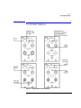
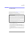
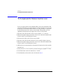
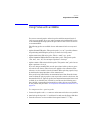
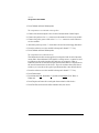
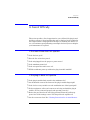
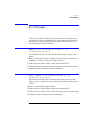
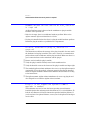
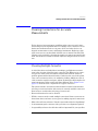
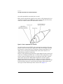
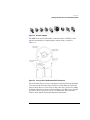
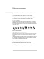
Agilent 83491/2/3/4A
Clock Recovery Modules
User’s Guide
© Copyright 2000-2004
Agilent Technologies
All Rights Reserved. Reproduction, adaptation, or translation without prior written
permission is prohibited,
except as allowed under copyright laws.
Agilent Part No. 83491-90014
Printed in USA
August, 2004
Agilent Technologies
Digital Signal Analysis
1400 Fountaingrove Parkway
Santa Rosa, CA 95403, USA
Notice.
The information contained in
this document is subject to
change without notice. Companies, names, and data used
in examples herein are fictitious unless otherwise noted.
Agilent Technologies makes
no warranty of any kind with
regard to this material, including but not limited to, the
implied warranties of merchantability and fitness for a
particular purpose. Agilent
Technologies shall not be liable for errors contained herein
or for incidental or consequential damages in connection with the furnishing,
performance, or use of this
material.
Restricted Rights Legend.
Use, duplication, or disclosure by the U.S. Government
is subject to restrictions as set
forth in subparagraph (c) (1)
(ii) of the Rights in Technical
Data and Computer Software
clause at DFARS 252.227-7013
for DOD agencies, and subparagraphs (c) (1) and (c) (2)
of the Commercial Computer
Software Restricted Rights
clause at FAR 52.227-19 for
other agencies.
ii
The CE mark is a registered trademark of
the European Community.
Safety Symbols.
CAUTION
The caution sign denotes a
hazard. It calls attention to a
procedure which, if not correctly performed or adhered
to, could result in damage to
or destruction of the product.
Do not proceed beyond a caution sign until the indicated
conditions are fully understood and met.
The CSA mark is a registered trademark of
the Canadian Standards Association.
The C-Tick mark is a
registered trademark
of the Australian Spectrum Management
Agency.
WARNING
The warning sign denotes a
hazard. It calls attention to a
procedure which, if not correctly performed or adhered
to, could result in injury or
loss of life. Do not proceed
beyond a warning sign until
the indicated conditions are
fully understood and met.
The instruction manual symbol. The product is marked with this
warning symbol when
it is necessary for the
user to refer to the
instructions in the
manual.
The laser radiation
symbol. This warning
symbol is marked on
products which have a
laser output.
The AC symbol is used
to indicate the
required nature of the
line module input
power.
| The ON symbols are
used to mark the positions of the instrument
power line switch.
❍ The OFF symbols
are used to mark the
positions of the instrument power line
switch.
ISM1-A
This text denotes the
instrument is an
Industrial Scientific
and Medical Group 1
Class A product.
Contents
1 Getting Started
Introduction 1-2
General Safety Considerations 1-4
Installation 1-5
Returning the Instrument for Service 1-12
2 Operation
Introduction 2-2
Front-Panel Features 2-3
Block Diagrams 2-6
To Display a Signal 2-9
To Compensate for Module Insertion Loss 2-10
Using Probes with an 83491A 2-11
3 Reference
Front-Panel Optical Adapters 3-2
In Case of Difficulty 3-3
Error Messages 3-5
Electrostatic Discharge Information 3-7
Cleaning Connections for Accurate Measurements 3-9
4 Specifications and Regulatory Information
83491A Specifications 4-3
83492A Specifications 4-4
83493A Specifications 4-6
83494A Specifications 4-8
83491/2/3/4A Operating Specifications 4-10
Regulatory Information 4-11
Contents-1
1
Introduction 1-2
General Safety Considerations 1-4
Installation 1-5
Step 1. Inspect the shipment 1-5
Step 2. Install the module 1-7
Step 3. Connect the front-panel cables 1-8
Step 4. Connect a modulated signal 1-10
Returning the Instrument for Service 1-12
Contacting Agilent Technologies 1-12
Getting Started
Getting Started
Introduction
Introduction
Agilent 83491/2/3/4A clock recovery modules are designed to operate in
86100-series infiniium Digital Communications Analyzers (DCA) and 83480A
DCAs. These modules recover clock and data information at standard telecom
and datacom rates. The resulting trigger signal is made available to the DCA
mainframe via a connector located on the module’s rear-panel. An external
front-panel cable passes the data signal, with some insertion loss, to the
receiver module.
Table 1-1. Module Features
Agilent Module
Input Connector
Selectable Rates (Mb/s)
83491A
50Ω electrical
155, 622, 1060, 1250, 2120, 2488, 2500
83492A
Multimode fiber (62.5/125 µm)
155, 622, 1060, 1250, 2120, 2488, 2500
83493A
Single-mode fiber (9/125 µm)
155, 622, 1250, 2488, 2500
83494A
Single-mode fiber (9/125 µm)
155, 622, 2488, 9953
83494A Option 106
Single-mode fiber (9/125 µm)
155, 622, 2488, 2666, 10664
83494A Option 107
Single-mode fiber (9/125 µm)
155, 622, 2488, 2666, 10709
WARNING
Light energy can radiate from the front panel OUTPUT connectors on
83492A, 83493A, and 83494A modules. The light emitted from these
connectors is the slightly attenuated light that is input to the frontpanel INPUT connector.
Online Help
On 86100-series infiniium DCAs, after installing the module as shown in this
chapter, you’ll find all user documentation (except programming) is located in
the instrument’s Help system. To access the Help system, complete the installation steps, turn on the 86100C, and click Contents on the Help menu.
1-2
Getting Started
Introduction
83494A Auxiliary
Clock Output
The 83494A module’s front-panel auxiliary clock output provides the recovered clock signal, refer to “Auxiliary outputs” on page 2-4. To recover the
clock at data rates greater than 2.5 Gb/s, the DCA mainframe must have one of
the following trigger options installed:
• 86100C Option 001, Enhanced Trigger
• 86100A/B Option 001, Divided Trigger
• 83480A Option 100, Divided Trigger
CAUTION
Fiber-optic connectors are easily damaged when connected to dirty or
damaged cables and accessories. The 83492A, 83493A, and 83494A front-panel
input connectors are no exception. When you use improper cleaning and
handling techniques, you risk expensive instrument repairs, damaged cables,
and compromised measurements. Before you connect any fiber-optic cable to
an 83492A, 83493A, or 83494A module, refer to “Cleaning Connections for
Accurate Measurements” on page 3-9.
CAUTION
The circuits on electrical inputs and outputs can be damaged by electrostatic
discharge (ESD). Therefore, avoid applying static discharges to any front or
rear-panel electrical connector. Before connecting any coaxial cable to a frontpanel connector, momentarily short the center and outer conductors of the
cable together. Avoid touching the front-panel connectors without first
touching the frame of the instrument. Be sure that the instrument is properly
earth-grounded to prevent buildup of static charge. Refer to “Electrostatic
Discharge Information” on page 3-7.
Figure 1-1. An Agilent 83493A installed in an Agilent 83480A mainframe
1-3
Getting Started
General Safety Considerations
General Safety Considerations
This product has been designed and tested in accordance with the standards
listed on the Manufacturer's Declaration of Conformity, and has been supplied
in a safe condition. The documentation contains information and warnings
that must be followed by the user to ensure safe operation and to maintain the
product in a safe condition.
The 83491/2/3/4A modules work only with Agilent digital communication analyzer mainframes. Refer to the mainframe documentation to ensure safe operation.
WARNING
Light energy can radiate from the front panel OUTPUT connectors on
83492A, 83493A, and 83494A modules. The light emitted from these
connectors is the slightly attenuated light that is input to the frontpanel INPUT connector.
WARNING
If this instrument is not used as specified, the protection provided by
the equipment could be impaired. This instrument must be used in a
normal condition (in which all means for protection are intact) only.
WARNING
To prevent electrical shock, disconnect the mainframe from mains
before cleaning. Use a dry cloth or one slightly dampened with water
to clean the external case parts. Do not attempt to clean internally.
WARNING
No operator serviceable parts inside. Refer servicing to qualified
personnel. To prevent electrical shock, do not remove covers.
CAUTION
This product is designed for use in Installation Category II and Pollution
Degree 2 per IEC 1010 and 664 respectively.
CAUTION
Electrostatic discharge (ESD) on or near input connectors can damage circuits
inside the instrument. Repair of damage due to misuse is not covered under
warranty. Before connecting any cable to the electrical input, momentarily
short the center and outer conductors of the cable together. Personnel should
be properly grounded, and should touch the frame of the instrument before
touching any connector.
1-4
Getting Started
Installation
Installation
Although some of the figures in the following procedure show an 83480A DCA
mainframe, the procedures equally apply to installing the module into an
86100-series DCA mainframe.
NOTE
If an 83491/2/3/4A module is installed in an 83480A DCA, the DCAs firmware
revision must be A.06.25 or later. If the module is installed in an Agilent 54750A
digitizing oscilloscope, you must first install the Agilent 83480K
communications firmware upgrade kit. To check the Agilent 83480A’s firmware
revision code, press the Utility key and then the System config softkey. The
firmware revision number is listed under the Frame section of the display.
Step 1. Inspect the shipment
❒ Inspect the shipping container and instrument for damage. Keep the shipping
container and cushioning material until you have inspected the contents of the
shipment for completeness and have checked the instrument mechanically and
electrically.
❒ Locate the shipping list. Verify that you received all the accessories on this list,
and all the options that you ordered. Table 1-2 on page 1-6 shows the external
front-panel cables that are supplied for each module.
❒ Make sure that the serial number listed on the module’s rear-panel label matches the serial number listed on the shipping document.
If your shipment is damaged or incomplete, save the packing materials and
notify both the shipping carrier and the nearest Agilent Technologies service
office. Agilent Technologies will arrange for repair or replacement of damaged
or incomplete shipments without waiting for a settlement from the transportation company. Notify the Agilent Technologies customer engineer of any problems.
1-5
Getting Started
Installation
Table 1-2. Supplied External Front-Panel Cables
Supplied Cable a
Agilent Part Number
83491A
RF cable, SMA-SMA, 9.75 cm
83491-20001
RF cable, SMA-SMA, 15.2 cm
83491-20002
83492A
Fiber-optic cable (semi-rigid), multimode, 14 cm
83492-20001
Fiber-optic cable (semi-rigid), multimode, 18.5 cm
83492-20002
83493A
Fiber-optic cable (semi-rigid), single-mode, 14 cm
83493-20001
83494A
Fiber-optic cable (semi-rigid), single-mode, 14 cm
83493-20001
a. Refer to “Step 3. Connect the front-panel cables” on page 1-8 for the use of these cables.
1-6
Getting Started
Installation
Step 2. Install the module
Up to two modules can be inserted into the 86100-series or 83480A DCA mainframe.
1 Install the 83491/2/3/4A module into the left slot on the mainframe. Installing
the module into the left slot ensures that the supplied adapter cable will fit.
Finger-tighten the knurled screw on the front panel of the plug-in module to
ensure that the module is securely seated in the mainframe.
Figure 1-2. Position of modules in the mainframe
2 Clean all optical interfaces as described in “Cleaning Connections for Accurate
Measurements” on page 3-9, before making measurements.
1-7
Getting Started
Installation
Step 3. Connect the front-panel cables
83491A Module
Perform this step if you are installing an 83491A module.
❒ Use the RF cable supplied with the module to connect the Electrical Output
connector on the 83491A to the input on the adjacent measurement module.
Use the short (83491-20001) or long (83491-20002) cable depending on the location of the input on the adjacent measurement module.
Figure 1-3. The adapter cable
83493/4A Modules Perform the following steps if you are installing an 83493/4A module.
1 Because you’ll connect an FC-PC fiber-optic cable in this procedure, confirm
that the receiver module’s optical input connector has an FC-PC adapter.
Fiber-optic adapters can be removed by hand turning them in the counterclockwise direction. Refer to “Front-Panel Optical Adapters” on page 3-2 for a
description of available adapters.
2 If you changed the adapter in step one, you can connect the original adapter to
the 83493/4A module’s front-panel Input connector.
3 Use the FC-PC semi-rigid fiber-optic cable supplied with the 83493/4 module
(83493-20001) to connect the Optical Output connector on the 83493/4A to the
input on the receiver module.
83492A Module
Perform the following steps if you are installing an 83492A module.
1-8
Getting Started
Installation
On 83492A modules, the front-panel fiber-optic connectors reverse input and
output roles depending on the wavelength of the signal. This is shown in
Figure 1-4. Signals in the 750 nm to 860 nm wavelength range are input to the
left connector and output from the right connector. Signals in the 1000 nm to
1600 nm wavelength range are input to the right connector and output from
the left connector.
1 Because you’ll connect an FC-PC fiber-optic cable in this procedure, confirm
that the receiver module’s optical input connector has an FC-PC adapter.
Fiber-optic adapters can be removed by hand turning them in the counterclockwise direction. Refer to “Front-Panel Optical Adapters” on page 3-2 for a
description of available adapters.
2 If you changed the adapter in step one, you can connect the original adapter to
the 83493/4A module’s front-panel input connector. See Figure 1-3 to identify
the input connector based on input wavelength.
3 Connect the supplied adapter cable as shown in Figure 1-3. Use the short cable
(83492-20002) when operating at 750 nm to 860 nm wavelengths. Use the long
cable (83492-20001) when operating at 1000 nm to 1600 nm wavelengths.
Figure 1-4. Input and output connections versus wavelength
1-9
Getting Started
Installation
Step 4. Connect a modulated signal
WARNING
Light energy can radiate from the front panel OUTPUT connectors on
83492A, 83493A, and 83494A modules. The light emitted from these
connectors is the slightly attenuated light that is input to the frontpanel INPUT connector.
CAUTION
83491A Modules: To prevent damage to the module, the maximum safe signal
input level is < ±5V. The input circuits can also be damaged by electrostatic
discharge (ESD). Before connecting any coaxial cable to the connectors,
momentarily short the center and outer conductors of the cable together. Avoid
touching the front-panel input connectors without first touching the frame of
the instrument. Be sure that the instrument is properly earth-grounded to
prevent buildup of static charge.
CAUTION
83492/3/4A Modules: To prevent damage to the module, the maximum signal
input level is < +3 dBm.
1 Turn on the mainframe and connect a modulated signal to the 83491/2/3/4A
module’s Input connector.
2 If you are using an 83480A DCA, press the Trigger key and then the Source
softkey. Then, select trigger 2 (the 83491/2/3/4A module) for the trigger source.
3 On the 83491/2/3/4A module, repeatedly press the SELECT key until a frontpanel light indicates the data rate of the signal. Avoid selecting a data rate that
is a multiple of the input signal. For example, don’t select a 622 Mb/s data rate
if the signal is really at 155 Mb/s.
4 Confirm that the Unlocked light is off. If using the 83494A, confirm that the
Trigger Loss light is off. If the UNLOCKED light is on (or TRIGGER LOSS light on the
83494A), clock recovery cannot be established on the signal.
5 Observe the Clock and Data outputs on DCA. Waveforms should be present. The
instrument is now ready for you to begin making measurements. If you cannot
get the clock recovery module to lock on the signal, make sure that you have
selected the correct data rate and that the mainframe trigger level is adjusted
appropriately.
Signals displayed using a data trigger are less reliable than using a recovered
clock. Signals triggered on data can also vary depending upon the trigger level.
1-10
Getting Started
Installation
Green and red data-rate lights
The data-rate indicator lights on the Agilent 83491/2/3A and Agilent 83494A Option 106
change color between red and green to show which data rate is selected. A red light
does not indicate a problem. A red light shows that the adjacent red data rate label is
selected. A green light shows that the adjacent green data rate label is selected.
Repeatedly pressing the SELECT key cycles through the selections in one color before
switching to the opposite color. On Agilent 83491A modules for example, the first selection cycle shows 155 Mb/s selected. The second selection cycle shows 1062 Mb/s
selected.
Agilent 83494A modules use only the green data-rate indicator light to show which data
rate is selected. Repeatedly pressing the SELECT key cycles through the available data
rates, as well as the Trigger On Data bypass mode.
Figure 1-5. Front-panel lights
1-11
Getting Started
Returning the Instrument for Service
Returning the Instrument for Service
The instructions in this section show you how to properly return the instrument for repair or calibration. Always call the Agilent Technologies Instrument
Call Center first to initiate service before returning your instrument to a service office. This ensures that the repair (or calibration) can be properly
tracked and that your instrument will be returned to you as quickly as possible. Call this number regardless of where you are located.
If the instrument is still under warranty or is covered by an Agilent Technologies maintenance contract, it will be repaired under the terms of the warranty
or contract (the warranty is at the front of this manual). If the instrument is
no longer under warranty or is not covered by an Agilent Technologies maintenance plan, Agilent Technologies will notify you of the cost of the repair after
examining the unit.
When an instrument is returned to a Agilent Technologies service office for
servicing, it must be adequately packaged and have a complete description of
the failure symptoms attached. When describing the failure, please be as specific as possible about the nature of the problem. Include copies of additional
failure information (such as the instrument failure settings, data related to
instrument failure, and error messages) along with the instrument being
returned.
Contacting Agilent Technologies
Call Center
For technical assistance, you can contact your local Agilent Call Center.
• In the Americas, call 1 (800) 829-4444
• In other regions, visit http://www.agilent.com/find/assist
Service Center
Before returning an instrument for service, you must first call the Agilent
Technologies Instrument Support Center.
• In all regions, call (800) 829-4444
1-12
Getting Started
Returning the Instrument for Service
Preparing the module for shipping
1 Write a complete description of the failure and attach it to the instrument.
Include any specific performance details related to the problem. The following
information should be returned with the instrument.
• Type of service required.
• Date instrument was returned for repair.
• Description of the problem:
• Whether problem is constant or intermittent.
• Whether instrument is temperature-sensitive.
• Whether instrument is vibration-sensitive.
• Instrument settings required to reproduce the problem.
• Performance data.
• Company name and return address.
• Name and phone number of technical contact person.
• Model number of returned instrument.
• Full serial number of returned instrument.
• List of any accessories returned with instrument.
2 Cover all front or rear-panel connectors that were originally covered when you
first received the instrument.
CAUTION
Cover electrical connectors to protect sensitive components from electrostatic
damage. Cover optical connectors to protect them from damage due to physical
contact or dust.
CAUTION
Instrument damage can result from using packaging materials other than the
original materials. Never use styrene pellets as packaging material. They do not
adequately cushion the instrument or prevent it from shifting in the carton.
They may also cause instrument damage by generating static electricity.
3 Pack the instrument in the original shipping containers. Original materials are
available through any Agilent Technologies office. Or, use the following
guidelines:
• Wrap the instrument in antistatic plastic to reduce the possibility of damage
caused by electrostatic discharge.
• For instruments weighing less than 54 kg (120 lb), use a double-walled, corrugated cardboard carton of 159 kg (350 lb) test strength.
• The carton must be large enough to allow approximately 7 cm (3 inches) on
1-13
Getting Started
Returning the Instrument for Service
all sides of the instrument for packing material, and strong enough to accommodate the weight of the instrument.
• Surround the equipment with approximately 7 cm (3 inches) of packing material, to protect the instrument and prevent it from moving in the carton. If
packing foam is not available, the best alternative is S.D-240 Air Cap™ from
Sealed Air Corporation (Commerce, California 90001). Air Cap looks like a
plastic sheet filled with air bubbles. Use the pink (antistatic) Air Cap™ to
reduce static electricity. Wrapping the instrument several times in this material will protect the instrument and prevent it from moving in the carton.
4 Seal the carton with strong nylon adhesive tape.
5 Mark the carton “FRAGILE, HANDLE WITH CARE”.
6 Retain copies of all shipping papers.
1-14
2
Introduction 2-2
Front-Panel Features 2-3
Block Diagrams 2-6
To Display a Signal 2-9
To Compensate for Module Insertion Loss
Using Probes with an 83491A 2-11
Operation
2-10
Operation
Introduction
Introduction
If you use an 83491/2/3/4A module in an 86100-series infiniium DCA, information on using the clock recovery modules, along with specifications, is
included in the instrument’s help system. To access the built-in information
system, referred to as Help, simply click Contents on the Help menu. GPIB
programming commands for the modules are documented in the 86100-series
infiniium DCA programmer’s guide.
If you use an 83491/2/3/4A module in an 83480A DCA, you’ll notice that, unlike
most modules designed to be used with the 83480A, the clock recovery modules do not include Channel keys or menus. Also, there are no GPIB programming commands for these modules when used in an 83480A mainframe.
Multimode module and single-mode reference receivers
Agilent Technologies does not recommend using the Agilent 83492A multimode module with single-mode reference receivers such as the
Agilent 83481A, 83482A, or 83485A,B modules. Connecting multimode to single-mode fibers causes large reflections and insertion loss because of the
reduction of the optical fiber’s core from 62.5 µm to 9 µm.
Single-mode module and multimode reference receivers
It is acceptable to use an Agilent 83493A or an 83494A single-mode module
with a multimode reference receiver such as the Agilent 83486A module. This
is true provided that single-mode fiber is connected to the Agilent 83493A or
83494A module’s front-panel INPUT connector.
2-2
Operation
Front-Panel Features
Front-Panel Features
Figure 2-1. Agilent 83491/2/3/4A front panels
2-3
Operation
Front-Panel Features
SELECT key
Pressing this key changes the data rate selection. The recovered and retimed
clock trigger is sent to the mainframe. The Trigger On Data selection is a bypass
mode where the data stream directly triggers the mainframe. Refer to “Block
Diagrams” on page 2-6 to view a schematic of the normal and bypass paths.
Green and red data-rate lights
The data-rate indicator lights on the Agilent 83491/2/3A and Agilent 83494A Option 106
change color between red and green to show which data rate is selected. A red light
does not indicate a problem. A red light shows that the adjacent red data rate label is
selected. A green light shows that the adjacent green data rate label is selected.
Repeatedly pressing the SELECT key cycles through the selections in one color before
switching to the opposite color. On Agilent 83491A modules for example, the first selection cycle shows 155 Mb/s selected. The second selection cycle shows 1062 Mb/s
selected.
Agilent 83494A modules use only the green data-rate indicator light to show which data
rate is selected. Repeatedly pressing the SELECT key cycles through the available data
rates, as well as the Trigger On Data bypass mode.
UNLOCKED
indicator
83491/2/3A
This light shows when clock recovery cannot be established on the signal. If a
clock rate is selected, the trigger output to the mainframe is disabled to prevent free-run triggering. However in bypass mode (Trigger On Data selected),
triggering is not disabled. When the UNLOCKED light is on, you can establish a
trigger on the data input to the reference receiver.
Trigger Loss
indicator
83494A
This light shows when clock recovery cannot be established on the signal. If a
clock rate is selected, the trigger output to the mainframe is disabled to prevent free-run triggering. However in bypass mode (Trigger On Data selected),
triggering is not disabled. When the Trigger Loss light is on, you can establish a
trigger on the data input to the reference receiver.
Auxiliary outputs
DATA connector: This connector provides a fully regenerated version of the
input signal. It is intended for monitoring purposes only and not for rigorous
eye mask compliance testing. The frequency response does not conform to the
requirements for eye mask testing as described in ITU-T G.957 and Bellcore
GR-253-CORE. On Agilent 83492A and 83493A modules, this port is amplitude stabilized for input signals greater than approximately –23 dBm. On
Agilent 83494A modules, this port is amplitude stabilized for input signals
greater than approximately –10 dBm.
2-4
Operation
Front-Panel Features
CLOCK connector: This connector provides the recovered clock signal. You can
use this signal to measure jitter transfer, because this output can track and follow input data with very fast jitter; it has a wide bandwidth jitter transfer function when compared to the recovered clock signal which is routed through a
rear-panel connector to the mainframe for triggering. Note that the CLOCK Auxiliary Output remains synchronized to input signals several dB below the onset of
errors at the DATA Auxiliary Output.
Input and Output
connectors
The input connectors pass the digitally modulated signal to the receiver module. The input signal, slightly attenuated and available at the OUTPUT connector, is connected to the input of the receiver module. The connectors on
optical modules include adapters which can easily be changed to match the
type of connectors that are used on your fiber-optic cables. Refer to “FrontPanel Optical Adapters” on page 3-2 for a description of the available adapters.
Multimode and single-mode connections
Agilent 83492A modules use multimode fiber. Connecting the output to the Optical
INPUT connector on Agilent 83481/2/5 single-mode modules results in large reflections
and insertion loss.
Agilent 83493A and 83494A modules use 9/125 µm single-mode fiber. Connecting multimode fiber to the Optical Input connector results in large reflections and insertion loss.
Recovered Clock
The recovered clock signal is routed directly to the 86100-series or 83480A
mainframes through the module’s rear panel. This output has a lower jitter
modulation bandwidth than the front-panel CLOCK Auxiliary Output. Because of
the reduced jitter modulation bandwidth on the mainframe trigger signal, a
more complete view of the jitter on the waveform data is obtained.
2-5
Operation
Block Diagrams
Block Diagrams
Figure 2-2. 83491A Block Diagram
Figure 2-3. 83492A and 83493A Block Diagram
2-6
Operation
Block Diagrams
Figure 2-4. 83494A Block Diagram
2-7
Operation
Block Diagrams
Figure 2-5. 83494A Option 106 Block Diagram
2-8
Operation
To Display a Signal
To Display a Signal
1 Install the module as described in “Installation” on page 1-5. Be sure to connect
all of the cables as described in the procedure.
2 Repeatedly press the SELECT key on the clock recovery module until the frontpanel light indicates the proper data rate of the signal.
Green and red data-rate lights
The data-rate indicator lights on the 83491/2/3A and 83494A Option 106 change color
between red and green to show which data rate is selected. A red light does not indicate
a problem. A red light shows that the adjacent red data rate label is selected. A green
light shows that the adjacent green data rate label is selected. Repeatedly pressing the
SELECT key cycles through the selections in one color before switching to the opposite
color. On 83491A modules for example, the first selection cycle shows 155 Mb/s
selected. The second selection cycle shows 1062 Mb/s selected.
Agilent 83494A modules use only the green data-rate indicator light to show which data
rate is selected. Repeatedly pressing the SELECT key cycles through the available data
rates, as well as the Trigger On Data bypass mode.
• If the UNLOCKED light is on (or TRIGGER LOSS light on the 83494A), clock recovery cannot be established on the signal.
• Avoid selecting a data rate that is a multiple of the input signal. For example,
don’t select a 622 Mb/s data rate if the signal is really at 155 Mb/s.
• If you cannot get the clock recovery module to lock on the signal, make sure
that you have selected the correct data rate and that the mainframe trigger
level is adjusted appropriately.
• Signals displayed using a data trigger are less reliable than using a recovered
clock. Signals triggered on data can also vary depending upon the trigger
level.
2-9
Operation
To Compensate for Module Insertion Loss
To Compensate for Module Insertion Loss
If you are using an 86100-series infiniium DCA, refer to the instrument’s help
system for information on compensating for module insertion loss. Use the following steps on an 83480A DCA to allow you to enter an offset to compensate
for the insertion loss of the clock recovery module. This provides accurate
amplitude measurements at the input to the clock recovery module.
1 Disconnect the cable from the clock recovery module’s Input connector.
2 Measure the signal using a power meter. You can use either the 83480A’s builtin power meter or an external power meter.
3 Reconnect the cable to the clock recovery module.
4 Disconnect the cable from the reference receiver module’s input connector.
5 Measure the signal using a power meter. You can use either the 83480A’s builtin power meter or an external power meter.
6 Subtract the two measurements to determine the insertion loss of the module.
Insertion loss: . . . . . . . . . . . . . . . . . . . . . . . . . . . . . . . . . . . . . . . . ____________
7 On the reference receiver module, press the front-panel channel SETUP key.
8 Press External scale, and set the Atten units to “decibel”.
9 Press Attenuation, and enter the value calculated in Step 6.
2-10
Operation
Using Probes with an 83491A
Using Probes with an 83491A
You can use external passive and active probes with the 83491A electrical
clock recovery module. If you are using an 86100-series infiniium DCA, refer
to the infiniium DCA’s help system; the procedures in this section are for use
on an 83480A DCA.
The following probes are available for use with 83491A clock recovery modules:
• Agilent N1020A TDR probe. This passive probe (1:1, 50Ω) provides a fixture
for positioning and holding the probe tip on the device being tested.
• Agilent 54701A 2.5 GHz active probe. This is a 100kΩ, 10:1, probe.
• Agilent 54006A 6 GHz handheld low-impedance probe. This passive probe
(10:1, 500Ω, 20:1, 1kΩ) has an input capacitance of 0.25 pf.
• Agilent 1163A 1 GHz resistive-divider probe. This passive 500Ω probe has an
input capacitance of 1.5 pf.
If you are using an 83480A DCA, use the procedures in this section to generate vertical scale factors. These factors are applied to the calibration of the
reference receiver module’s electrical channel. When selecting a probe, keep
in mind that the input impedance of the 83491A is 50Ω.
If the probe being calibrated has an attenuation factor that allows the instrument to adjust the gain to produce even steps in the vertical scale factors, the
instrument will do so. Typically, probes have standard attenuation factors such
as divide by 10, divide by 20, or divide by 100. Because the following procedures include compensation for insertion loss of the clock recovery module,
do not perform the procedure “To Compensate for Module Insertion Loss” on
page 2-10.
To compensate for a passive probe
1 Connect the probe to the Input connector on the 83491A clock recovery module.
2 Attach the probe tip to the CAL hook that is located near the floppy disk drive.
3 Press the reference receiver module’s front-panel channel SETUP key.
2-11
Operation
Using Probes with an 83491A
4 Press Calibrate and then Calibrate probe.
To compensate an 54701A active probe
1 Connect the 83491A output to the electrical measurement channel input.
2 Connect the probe to the Input connector on the 83491A clock recovery module.
3 Connect the probe power cable to the Probe Power connector on the reference
receiver module.
4 Attach the probe tip to the CAL hook that is located near the floppy disk drive.
5 Press the reference receiver module’s front-panel channel SETUP key.
6 Press Calibrate and then Calibrate probe.
To compensate for other devices
The information in this section applies to both optical and electrical measurements. Since the mainframe’s CAL signal is a voltage source, it cannot be used
to calibrate to the probe tip when the units are set to Ampere, Watt, or
Unknown. Instead, set the external gain and external offset to compensate for
the actual characteristics of the device. If you do not know the actual characteristics, you can refer to the typical specifications that came with the device.
1 Press the reference receiver module’s front-panel channel SETUP key.
2 Press External scale.
3 Press Atten units Ratio, Attenuation 1:1, and then Units Ampere (Volt, Watt, or
Unknown).
4 Press Ext gain, and enter the actual gain characteristics of the device.
5 Press Ext offset, and enter the offset introduced by the device.
2-12
3
Front-Panel Optical Adapters 3-2
In Case of Difficulty 3-3
Error Messages 3-5
Electrostatic Discharge Information 3-7
Cleaning Connections for Accurate Measurements
Reference
3-9
Reference
Front-Panel Optical Adapters
Front-Panel Optical Adapters
Front Panel
Fiber-Optic
Adapter
Description
Agilent Part Number
Diamond HMS-10
81000AI
FC/PCa
81000FI
D4
81000GI
SC
81000KI
DIN
81000SI
ST
81000VI
Biconic
81000WI
Dust Covers
FC connector
1005-0594
Diamond HMS-10 connector
1005-0593
DIN connector
1005-0595
ST connector
1005-0596
SC connector
1005-0597
a. The FC/PC adapter is the standard adapter supplied with the instrument.
3-2
Reference
In Case of Difficulty
In Case of Difficulty
This section provides a list of suggestions for you to follow if the plug-in module fails to operate. A list of messages that may be displayed is also included in
this chapter. Before calling Agilent Technologies or returning the unit for service, a few minutes spent performing some simple checks may save waiting for
your instrument to be repaired.
If the mainframe does not operate
❒ Is the line fuse good?
❒ Does the line socket have power?
❒ Is the unit plugged in to the proper ac power source?
❒ Is the mainframe turned on?
❒ Is the rear-panel line switch set to on?
❒ Will the mainframe power up without the plug-in module installed?
If the plug-in does not operate
❒ Is the plug-in module firmly seated in the mainframe slot?
❒ Are the knurled screws at the bottom of the plug-in module finger-tight?
❒ Is the clock recovery module set to the modulation rate of the input signal?
❒ If other equipment, cables, and connectors are being used with the plug-in
module, are they connected properly and operating correctly?
❒ Review the procedure for the test being performed when the problem appeared. Are all the settings correct? Can the problem be reproduced?
❒ Are the connectors clean? See “Cleaning Connections for Accurate Measure-
3-3
Reference
In Case of Difficulty
ments” on page 3-9 for more information.
❒ Make sure that the instrument is ready to acquire data.
❒ Find any signals on the channel inputs by using the Autoscale function.
❒ See if any signals are present at the channel inputs by using Freerun triggering.
❒ Make sure Channel Display is on.
❒ Make sure the channel offset is adjusted so the waveform is not clipped off the
display.
❒ Make sure the mainframe identifies the plug-in module:
• One the 86100-series DCA, select the All Calibrations command on the Calibrate menu. Confirm that the Model number and Serial Number are listed
in the displayed dialog box.
• On the 83480A DCA, press Utility, then System config. Confirm that the Model
number is listed in the box labeled “Plug-ins”. If “~known” is displayed instead of the model number of the plug-in module, remove and reinsert the
plug-in module in the same slot. If “~known” is still displayed, the mainframe
may need to have the latest operating system firmware installed. Options
001 and 002 provide this firmware on a 3.5 inch diskette. To load new firmware, follow the instructions provided with this diskette. If you do not have
the optional diskette, contact your local Agilent Technologies service office
(refer to “Contacting Agilent Technologies” on page 1-12).
If the model number of the plug-in module is listed, the mainframe has identified the plug-in.
3-4
Reference
Error Messages
Error Messages
This section provides description of error messages that are displayed if you
are using the module in an 83480A DCA. If you are using an 86100-series infiniium DCA, refer to the instrument’s help system for information on error
messages displayed on that mainframe.
Memory error occurred in plug-in_:Try
reinstalling plug-in
The mainframe could not correctly read the contents of the memory in the
plug-in.
❒ Remove and reinstall the plug-in module. Each time a plug-in is installed, the
mainframe re-reads the memory in the plug-in module.
❒ Verify the plug-in module is firmly seated in the mainframe slot.
❒ Verify the knurled screws at the bottom of the plug-in module are finger-tight.
❒ Install the plug-in in a different slot in the mainframe.
Busy timeout occurred with plug-in_:Try
reinstalling plug-in
The mainframe is having trouble communicating with the plug-in module.
Make sure there is a good connection between the mainframe and the plug-in
module.
❒ Remove and reinstall the plug-in module.
❒ Verify the plug-in module is firmly seated in the mainframe slot.
❒ Verify the knurled screws at the bottom of the plug-in module are finger-tight.
❒ Install the plug-in in a different slot in the mainframe.
3-5
Reference
Communications failure exists at slot_:Service is required
Communications failure exists at slot_:Service
is required
An illegal hardware state is detected at the mainframe-to-plug-in module
interface of the specified slot.
• If the slot is empty, there is a mainframe hardware problem. Refer to the
Agilent 83480A, Agilent 54750A Service Guide.
• If a plug-in is installed in the slot, there is a plug-in module hardware problem.
Return the plug-in module to a qualified service department.
ID error occurred in plug-in_:Service is
required
The information read from the memory of the plug-in module does not match
the hardware in the plug-in module. This can be caused by a communication
problem between the mainframe and the plug-in module. Make sure there is a
good connection between the mainframe and the plug-in.
❒ Remove and re-install the plug-in module.
❒ Verify the plug-in module is firmly seated in the mainframe slot.
❒ Verify the knurled screws at the bottom of the plug-in module are finger tight.
❒ The standard Agilent 54750A mainframe does not accept the Agilent 83491/2/
3/4A module. To use the module, a firmware upgrade must first be installed.
Order the Agilent 83480K communications firmware kit and install according
to the instructions.
❒ The Agilent 83480A, Agilent 54750A mainframes do not accept plug-in modules designed for use with the Agilent 54710A, 54720A.
Plug-in is not supported:System firmware
upgrade is needed
The mainframe may need to have the latest operating system firmware
installed. Options 001 and 002 provide this firmware on a 3.5 inch diskette. To
load the new firmware, follow the instructions provided with the diskette. If
you do not have the optional diskette, contact your local Agilent Technologies
service office.
3-6
Reference
Electrostatic Discharge Information
Electrostatic Discharge Information
Electrostatic discharge (ESD) can damage or destroy electronic components.
All work on electronic assemblies should be performed at a static-safe work
station. The following figure shows an example of a static-safe work station
using two types of ESD protection:
• Conductive table-mat and wrist-strap combination.
• Conductive floor-mat and heel-strap combination.
Figure 3-1. Static-safe work station
3-7
Reference
Electrostatic Discharge Information
Both types, when used together, provide a significant level of ESD protection.
Of the two, only the table-mat and wrist-strap combination provides adequate
ESD protection when used alone.
To ensure user safety, the static-safe accessories must provide at least 1 MΩ of
isolation from ground. Refer to Table 3-1 for information on ordering staticsafe accessories.
WARNING
These techniques for a static-safe work station should not be used
when working on circuitry with a voltage potential greater than 500
volts.
Reducing ESD Damage
The following suggestions may help reduce ESD damage that occurs during
testing and servicing operations.
• Personnel should be grounded with a resistor-isolated wrist strap before removing any assembly from the unit.
• Be sure all instruments are properly earth-grounded to prevent a buildup of
static charge.
Table 3-1. Static-Safe Accessories
Agilent Part
Number
Description
9300-0797
Set includes: 3M static control mat 0.6 m × 1.2 m (2 ft× 4 ft) and 4.6 cm (15
ft) ground wire. (The wrist-strap and wrist-strap cord are not included. They
must be ordered separately.)
9300-0980
Wrist-strap cord 1.5 m (5 ft)
9300-1383
Wrist-strap, color black, stainless steel, without cord, has four adjustable
links and a 7 mm post-type connection.
9300-1169
ESD heel-strap (reusable 6 to 12 months).
3-8
Reference
Cleaning Connections for Accurate Measurements
Cleaning Connections for Accurate
Measurements
Today, advances in measurement capabilities make connectors and connection techniques more important than ever. Damage to the connectors on calibration and verification devices, test ports, cables, and other devices can
degrade measurement accuracy and damage instruments. Replacing a damaged connector can cost thousands of dollars, not to mention lost time! This
expense can be avoided by observing the simple precautions presented in this
book. This book also contains a brief list of tips for caring for electrical connectors.
Choosing the Right Connector
A critical but often overlooked factor in making a good lightwave measurement is the selection of the fiber-optic connector. The differences in connector types are mainly in the mechanical assembly that holds the ferrule in
position against another identical ferrule. Connectors also vary in the polish,
curve, and concentricity of the core within the cladding. Mating one style of
cable to another requires an adapter. Agilent Technologies offers adapters for
most instruments to allow testing with many different cables. Figure 3-2 on
page 3-10 shows the basic components of a typical connectors.
The system tolerance for reflection and insertion loss must be known when
selecting a connector from the wide variety of currently available connectors.
Some items to consider when selecting a connector are:
• How much insertion loss can be allowed?
• Will the connector need to make multiple connections? Some connectors are
better than others, and some are very poor for making repeated connections.
• What is the reflection tolerance? Can the system take reflection degradation?
• Is an instrument-grade connector with a precision core alignment required?
• Is repeatability tolerance for reflection and loss important? Do your specifica-
3-9
Reference
Cleaning Connections for Accurate Measurements
tions take repeatability uncertainty into account?
• Will a connector degrade the return loss too much, or will a fusion splice be required? For example, many DFB lasers cannot operate with reflections from
connectors. Often as much as 90 dB isolation is needed.
Figure 3-2. Basic components of a connector.
Over the last few years, the FC/PC style connector has emerged as the most
popular connector for fiber-optic applications. While not the highest performing connector, it represents a good compromise between performance, reliability, and cost. If properly maintained and cleaned, this connector can
withstand many repeated connections.
However, many instrument specifications require tighter tolerances than most
connectors, including the FC/PC style, can deliver. These instruments cannot
tolerate connectors with the large non-concentricities of the fiber common
with ceramic style ferrules. When tighter alignment is required, Agilent
Technologies instruments typically use a connector such as the Diamond
HMS-10, which has concentric tolerances within a few tenths of a micron. Agilent Technologies then uses a special universal adapter, which allows other
cable types to mate with this precision connector. See Figure 3-3.
3-10
Reference
Cleaning Connections for Accurate Measurements
Figure 3-3. Universal adapters
The HMS-10 encases the fiber within a soft nickel silver (Cu/Ni/Zn) center
which is surrounded by a tough tungsten carbide casing, as shown in
Figure 3-4.
Figure 3-4. Cross-section of the Diamond HMS-10 connector.
The nickel silver allows an active centering process that permits the glass fiber
to be moved to the desired position. This process first stakes the soft nickel
silver to fix the fiber in a near-center location, then uses a post-active staking
to shift the fiber into the desired position within 0.2 µm. This process, plus the
keyed axis, allows very precise core-to-core alignments. This connector is
found on most Agilent Technologies lightwave instruments.
3-11
Reference
Cleaning Connections for Accurate Measurements
The soft core, while allowing precise centering, is also the chief liability of the
connector. The soft material is easily damaged. Care must be taken to minimize excessive scratching and wear. While minor wear is not a problem if the
glass face is not affected, scratches or grit can cause the glass fiber to move
out of alignment. Also, if unkeyed connectors are used, the nickel silver can be
pushed onto the glass surface. Scratches, fiber movement, or glass contamination will cause loss of signal and increased reflections, resulting in poor return
loss.
Inspecting Connectors
Because fiber-optic connectors are susceptible to damage that is not immediately obvious to the naked eye, poor measurements result without the user
being aware. Microscopic examination and return loss measurements are the
best way to ensure good measurements. Good cleaning practices can help
ensure that optimum connector performance is maintained. With glass-toglass interfaces, any degradation of a ferrule or the end of the fiber, any stray
particles, or finger oil can have a significant effect on connector performance.
Where many repeat connections are required, use of a connector saver or
patch cable is recommended.
Figure 3-5 shows the end of a clean fiber-optic cable. The dark circle in the
center of the micrograph is the fiber’s 125 µm core and cladding which carries
the light. The surrounding area is the soft nickel-silver ferrule. Figure 3-6
shows a dirty fiber end from neglect or perhaps improper cleaning. Material is
smeared and ground into the end of the fiber causing light scattering and poor
reflection. Not only is the precision polish lost, but this action can grind off the
glass face and destroy the connector.
Figure 3-7 shows physical damage to the glass fiber end caused by either
repeated connections made without removing loose particles or using
improper cleaning tools. When severe, the damage of one connector end can
be transferred to another good connector endface that comes in contact with
the damaged one. Periodic checks of fiber ends, and replacing connecting
cables after many connections is a wise practice.
The cure for these problems is disciplined connector care as described in the
following list and in “Cleaning Connectors” on page 3-16.
3-12
Reference
Cleaning Connections for Accurate Measurements
Use the following guidelines to achieve the best possible performance when
making measurements on a fiber-optic system:
• Never use metal or sharp objects to clean a connector and never scrape the
connector.
• Avoid matching gel and oils.
Figure 3-5. Clean, problem-free fiber end and ferrule.
Figure 3-6. Dirty fiber end and ferrule from poor cleaning.
3-13
Reference
Cleaning Connections for Accurate Measurements
Figure 3-7. Damage from improper cleaning.
While these often work well on first insertion, they are great dirt magnets. The
oil or gel grabs and holds grit that is then ground into the end of the fiber.
Also, some early gels were designed for use with the FC, non-contacting connectors, using small glass spheres. When used with contacting connectors,
these glass balls can scratch and pit the fiber. If an index matching gel or oil
must be used, apply it to a freshly cleaned connector, make the measurement,
and then immediately clean it off. Never use a gel for longer-term connections
and never use it to improve a damaged connector. The gel can mask the extent
of damage and continued use of a damaged fiber can transfer damage to the
instrument.
• When inserting a fiber-optic cable into a connector, gently insert it in as
straight a line as possible. Tipping and inserting at an angle can scrape material
off the inside of the connector or even break the inside sleeve of connectors
made with ceramic material.
• When inserting a fiber-optic connector into a connector, make sure that the fiber end does not touch the outside of the mating connector or adapter.
• Avoid over tightening connections.
Unlike common electrical connections, tighter is not better. The purpose of
the connector is to bring two fiber ends together. Once they touch, tightening
only causes a greater force to be applied to the delicate fibers. With connectors that have a convex fiber end, the end can be pushed off-axis resulting in
misalignment and excessive return loss. Many measurements are actually
improved by backing off the connector pressure. Also, if a piece of grit does
happen to get by the cleaning procedure, the tighter connection is more likely
to damage the glass. Tighten the connectors just until the two fibers touch.
3-14
Reference
Cleaning Connections for Accurate Measurements
• Keep connectors covered when not in use.
• Use fusion splices on the more permanent critical nodes. Choose the best connector possible. Replace connecting cables regularly. Frequently measure the
return loss of the connector to check for degradation, and clean every connector, every time.
All connectors should be treated like the high-quality lens of a good camera.
The weak link in instrument and system reliability is often the inappropriate
use and care of the connector. Because current connectors are so easy to use,
there tends to be reduced vigilance in connector care and cleaning. It takes
only one missed cleaning for a piece of grit to permanently damage the glass
and ruin the connector.
Measuring insertion loss and return loss
Consistent measurements with your lightwave equipment are a good indication that you have good connections. Since return loss and insertion loss are
key factors in determining optical connector performance they can be used to
determine connector degradation. A smooth, polished fiber end should produce a good return-loss measurement. The quality of the polish establishes
the difference between the “PC” (physical contact) and the “Super PC” connectors. Most connectors today are physical contact which make glass-to-glass
connections, therefore it is critical that the area around the glass core be clean
and free of scratches. Although the major area of a connector, excluding the
glass, may show scratches and wear, if the glass has maintained its polished
smoothness, the connector can still provide a good low level return loss connection.
If you test your cables and accessories for insertion loss and return loss upon
receipt, and retain the measured data for comparison, you will be able to tell in
the future if any degradation has occurred. Typical values are less than 0.5 dB
of loss, and sometimes as little as 0.1 dB of loss with high performance connectors. Return loss is a measure of reflection: the less reflection the better
(the larger the return loss, the smaller the reflection). The best physically
contacting connectors have return losses better than 50 dB, although 30 to
40 dB is more common.
3-15
Reference
Cleaning Connections for Accurate Measurements
Visual inspection of fiber ends
Visual inspection of fiber ends can be helpful. Contamination or imperfections
on the cable end face can be detected as well as cracks or chips in the fiber
itself. Use a microscope (100X to 200X magnification) to inspect the entire
end face for contamination, raised metal, or dents in the metal as well as any
other imperfections. Inspect the fiber for cracks and chips. Visible imperfections not touching the fiber core may not affect performance (unless the
imperfections keep the fibers from contacting).
WARNING
Always remove both ends of fiber-optic cables from any instrument,
system, or device before visually inspecting the fiber ends. Disable all
optical sources before disconnecting fiber-optic cables. Failure to do
so may result in permanent injury to your eyes.
Cleaning Connectors
The procedures in this section provide the proper steps for cleaning fiberoptic cables and Agilent Technologies universal adapters. The initial cleaning,
using the alcohol as a solvent, gently removes any grit and oil. If a caked-on
layer of material is still present, (this can happen if the beryllium-copper sides
of the ferrule retainer get scraped and deposited on the end of the fiber during
insertion of the cable), a second cleaning should be performed. It is not
uncommon for a cable or connector to require more than one cleaning.
CAUTION
Agilent Technologies strongly recommends that index matching compounds
not be applied to their instruments and accessories. Some compounds, such as
gels, may be difficult to remove and can contain damaging particulates. If you
think the use of such compounds is necessary, refer to the compound
manufacturer for information on application and cleaning procedures.
Table 3-2. Cleaning Accessories
Item
Agilent Part Number
Any commercially available denatured alcohol
—
Cotton swabs
8520-0023
Small foam swabs
9300-1223
Compressed dust remover (non-residue)
8500-5262
3-16
Reference
Cleaning Connections for Accurate Measurements
Table 3-3. Dust Caps Provided with Lightwave Instruments
Item
Agilent Part Number
Laser shutter cap
08145-64521
FC/PC dust cap
08154-44102
Biconic dust cap
08154-44105
DIN dust cap
5040-9364
HMS10/dust cap
5040-9361
ST dust cap
5040-9366
To clean a non-lensed connector
CAUTION
Do not use any type of foam swab to clean optical fiber ends. Foam swabs can
leave filmy deposits on fiber ends that can degrade performance.
1 Apply pure isopropyl alcohol to a clean lint-free cotton swab or lens paper.
Cotton swabs can be used as long as no cotton fibers remain on the fiber end
after cleaning.
2 Clean the ferrules and other parts of the connector while avoiding the end of
the fiber.
3 Apply isopropyl alcohol to a new clean lint-free cotton swab or lens paper.
4 Clean the fiber end with the swab or lens paper.
Do not scrub during this initial cleaning because grit can be caught in the
swab and become a gouging element.
5 Immediately dry the fiber end with a clean, dry, lint-free cotton swab or lens
paper.
6 Blow across the connector end face from a distance of 6 to 8 inches using
filtered, dry, compressed air. Aim the compressed air at a shallow angle to the
fiber end face. Nitrogen gas or compressed dust remover can also be used.
3-17
Reference
Cleaning Connections for Accurate Measurements
CAUTION
Do not shake, tip, or invert compressed air canisters, because this releases
particles in the can into the air. Refer to instructions provided on the
compressed air canister.
7 As soon as the connector is dry, connect or cover it for later use.
If the performance, after the initial cleaning, seems poor try cleaning the connector again. Often a second cleaning will restore proper performance. The
second cleaning should be more arduous with a scrubbing action.
To clean an adapter
The fiber-optic input and output connectors on many Agilent Technologies
instruments employ a universal adapter such as those shown in the following
picture. These adapters allow you to connect the instrument to different types
of fiber-optic cables.
Figure 3-8. Universal adapters.
1 Apply isopropyl alcohol to a clean foam swab.
Cotton swabs can be used as long as no cotton fibers remain after cleaning. The
foam swabs listed in this section’s introduction are small enough to fit into
adapters.
Although foam swabs can leave filmy deposits, these deposits are very thin, and
the risk of other contamination buildup on the inside of adapters greatly outweighs the risk of contamination by foam swabs.
2 Clean the adapter with the foam swab.
3 Dry the inside of the adapter with a clean, dry, foam swab.
4 Blow through the adapter using filtered, dry, compressed air.
Nitrogen gas or compressed dust remover can also be used. Do not shake, tip,
or invert compressed air canisters, because this releases particles in the can
into the air. Refer to instructions provided on the compressed air canister.
3-18
4
83491A Specifications 4-3
83492A Specifications 4-4
83493A Specifications 4-6
83494A Specifications 4-8
83491/2/3/4A Operating Specifications
Regulatory Information 4-11
4-10
Specifications and Regulatory
Information
Specifications and Regulatory Information
Specifications and Regulatory Information
Specifications and Regulatory Information
This chapter lists specifications and characteristics of the clock recovery modules. Specifications apply over the temperature range +15°C to +35°C (unless
otherwise noted) after the instrument’s temperature has been stabilized after
60 minutes of continuous operation.
Specifications
Specifications described warranted performance.
Characteristics
Characteristics provide useful, nonwarranted, information about the functions and performance of the instrument. Characteristics are printed in
italics.
Calibration cycle
Agilent Technologies warrants instrument specifications over the recommended calibration interval. To maintain specifications, periodic recalibrations
are necessary. We recommend that the Agilent 83491/2/3/4A be calibrated at
an Agilent Technologies service facility every 24 months.
4-2
Specifications and Regulatory Information
83491A Specifications
83491A Specifications
Table 4-1. 83491A Specifications
Clock Recovery Phase Locked Loop Bandwidth (characteristic)
Internal Path Triggering
External Output
50 to 70 kHz
4 to 5 MHz
Clock recovery rates (NRZ coding)
155.52 Mb/s
622.08 Mb/s
1062.50 Mb/s
1250 Mb/s
2125.00 Mb/s
2488.32 Mb/s
2500.00 Mb/s
±0.1%
±0.1%
±0.1%
±0.1%
±0.1%
±0.1%
±0.1%
Data triggering (characteristic)
50 Mb/s to 2500 Mb/s
Operating input power level a b
Triggering operation, all rates
10 –10 BER, all rates c
–10 dBm to 3 dBm
–10 dBm to 3 dBm
Insertion loss (through path)
DC through 2500 MHz
≤ 7 dB
Output jitter, all rates d
0.0125 UIrm s
Maximum continuous electrical power before damage (characteristic)
1W peak
DATA and CLOCK output amplitude, all rates (characteristic)
0.5Vp-p
INPUT electrical return loss
DC through 1250 MHz (characteristic)
1250 MHz through 2500 MHz (characteristic)
≥ 20 dB
≥ 15 dB
DATA and CLOCK electrical return loss
50 MHz through 2000 MHz (characteristic)
2000 MHz through 2500 MHz (characteristic)
≥ 10 dB
≥ 6 dB
a.
b.
c.
d.
Source extinction ratio ≥ 8.2 dB when measured per TIA/EIA OFSTP-4A.
Operating power level applies over temperature range 25°C ± 5°.
Better than 10 –10 BER when tested with PRBS 223–1 pattern.
Measured on an oscilloscope eye diagram with PRBS 223–1 test pattern.
4-3
Specifications and Regulatory Information
83492A Specifications
83492A Specifications
Table 4-2. 83492A Specifications (1 of 2)
Wavelength range (characteristic)
750 nm to 860 nm and
1000 nm to 1600 nm
Optical INPUT and OUTPUT fiber (characteristic)
62.5/125 multimode
Optical insertion loss (through path) a
750 nm to 860 nm
1000 nm to 1600 nm
≤ 5.0 dB
≤ 5.0 dB
Optical return loss b
≥ 28 dB
Clock Recovery Phase Locked Loop Bandwidth (characteristic)
Internal Path Triggering
External Output
50 to 70 kHz
4 to 5 MHz
Clock recovery rates (NRZ coding)
155.52 Mb/s
622.08 Mb/s
1062.50 Mb/s
1250 Mb/s
2125.00 Mb/s
2488.32 Mb/s
2500.00 Mb/s
±0.1%
±0.1%
±0.1%
±0.1%
±0.1%
±0.1%
±0.1%
Data triggering (characteristic)
50 Mb/s to 2500 Mb/s
Operating input power level c d
750 nm to 860 nm
Triggering operation, all rates
10 –10 BER, all rates e
1000 nm to 1600 nm
Triggering operation, all rates
10 –10 BER, all rates f
Output jitter, all rates g
4-4
–10 dBm to 3 dBm
–10 dBm to 3 dBm
–13 dBm to 3 dBm
–13 dBm to 3 dBm
0.0125 UIrm s
Specifications and Regulatory Information
83492A Specifications
Table 4-2. 83492A Specifications (2 of 2)
Maximum continuous optical power before damage (characteristic)
10 mW peak
DATA and CLOCK output amplitude, all rates (characteristic)
0.5Vp-p
DATA and CLOCK electrical return loss
50 MHz through 2000 MHz (characteristic)
2000 MHz through 2500 MHz (characteristic)
≥ 10 dB
≥ 6 dB
a. Minimum loss in 850 nm window.
b. Single-mode backreflection tested with FC/PC adapter and single-mode fiber. Optical output terminated
with > 33 dB return loss. Return loss with fully filled 62.5 µm core multimode fiber may be slightly lower.
c. Source extinction ratio ≥ 8.2 dB when measured per TIA/EIA OFSTP-4A.
d. Operating power level applies over temperature range 25°C ± 5°.
e. Better than 10 –10 BER when tested with PRBS 223–1 pattern.
f. Better than 10 –10 BER when tested with PRBS 223–1 pattern.
g. Measured on an oscilloscope eye diagram with PRBS 223–1 test pattern.
4-5
Specifications and Regulatory Information
83493A Specifications
83493A Specifications
Table 4-3. 83493A Specifications
Wavelength range (characteristic)
1000 nm to 1600 nm
Optical INPUT fiber (characteristic)
9/125 single mode
Optical insertion loss (through path)
≤ 1.5 dB
Optical return loss a
≥ 28 dB
Clock Recovery Phase Locked Loop Bandwidth (characteristic)
Internal Path Triggering
External Output
50 to 70 kHz
4 to 5 MHz
Clock recovery rates (NRZ coding)
155.52 Mb/s
622.08 Mb/s
1250 Mb/s
2488.32 Mb/s
2500.00 Mb/s
±0.1%
±0.1%
±0.1%
±0.1%
±0.1%
Data triggering (characteristic)
50 Mb/s to 2500 Mb/s
Operating input power level b c
Triggering operation, all rates
10 –10 BER, all rates d
–20 dBm to 3 dBm
–17 dBm to 3 dBm
Output jitter, all rates e
0.0125 UIrm s
Maximum continuous optical power before damage (characteristic)
10 mW peak
DATA and CLOCK output amplitude, all rates (characteristic)
0.5Vp-p
DATA and CLOCK output electrical return loss
50 MHz through 2500 MHz (characteristic)
2.5 GHz through 10 GHz (characteristic)
≥ 10 dB
≥ 8 dB
a. Tested with FC/PC adapter. Optical output terminated without > 33 dB return loss.
4-6
Specifications and Regulatory Information
83493A Specifications
b.
c.
d.
e.
Source extinction ratio ≥ 8.2 dB when measured per TIA/EIA OFSTP-4A.
Operating power level applies over temperature range 25°C ± 5°.
Better than 10 –10 BER when tested with PRBS 223–1 pattern.
Measured on an oscilloscope eye diagram with PRBS 223–1 test pattern.
4-7
Specifications and Regulatory Information
83494A Specifications
83494A Specifications
Table 4-4. 83494A Specifications (1 of 2)
Wavelength range (characteristic)
1200 nm to 1600 nm
Optical INPUT fiber (characteristic)
9/125 single mode
Optical insertion loss (through path)
1.5 dB
Optical return loss a
≥ 28 dB
Clock Recovery Phase Locked Loop Bandwidth (characteristic)
Internal Path Triggering
External Output
90 kHz
4 to 5 MHz
Clock recovery rates (NRZ coding)
155.52 Mb/s
622.08 Mb/s
2488.32 Mb/s
2666.06 Mb/s (Options 106 and 107)
9953.00 Mb/s (Standard)
10312.500 Mb/s (Option 103)
10664.228 Mb/s (Option 106)
10709.225316 Mb/s (Option 107)
±0.1%
±0.1%
±0.1%
±0.1%
±0.03%
±0.03%
±0.03%
±0.03%
Data triggering (characteristic)
50 Mb/s to 2500 Mb/s
Operating input power level b c
Triggering operation
9953.00 Mb/s, 10312.500 Mb/s, 10664.228 Mb/s, and
10709.225316 Mb/s
Triggering operation, all other rates
–8 dBm to 3 dBm
10 –10 BER, all rates d
4-8
-12 dBm to 3 dBm
-14 dBm to 3 dBm (typical)
0 dBm
Specifications and Regulatory Information
83494A Specifications
Table 4-4. 83494A Specifications (2 of 2)
Output jitter e
all rates
155.52 Mb/s
622.08 Mb/s
2488.32 Mb/s
0.02 UIrm s
0.01 UIrm s (typical)
0.01 UIrm s (typical)
0.01 UIrm s (typical)
Maximum continuous optical power before damage (characteristic)
10 mW peak
DATA and CLOCK output amplitude, all rates (characteristic)
0.5Vp-p
DATA and CLOCK output electrical return loss
50 MHz through 2500 MHz (characteristic)
2.5 GHz through 10 GHz (characteristic)
≥ 10 dB
≥ 8 dB
a.
b.
c.
d.
e.
Tested with FC/PC adapter. Optical output terminated without > 33 dB return loss.
Source extinction ratio ≥ 8.2 dB when measured per TIA/EIA OFSTP-4A.
Operating power level applies over temperature range 25°C ± 5°.
Better than 10 –10 BER when tested with PRBS 223–1 pattern.
Measured on an oscilloscope eye diagram with PRBS 223–1 test pattern.
4-9
Specifications and Regulatory Information
83491/2/3/4A Operating Specifications
83491/2/3/4A Operating Specifications
Table 4-5. Operating Specifications
Use
Indoor
Temperature
Operating
Non-operating
0°C to +55°C
–40°C to +70°C
Altitude
Operating
Non-operating
4600 m (15,000 ft)
15,300 m (50,000 ft)
Humidity
Operating
Non-operating
up to 90% relative humidity at <35°C
up to 90% relative humidity at <35°C
Net weight
approximately 1.2 kg (2.6 lb.)
Shipping weight
approximately 2.1 kg (4.6 lb.)
Dimensions H x W x D
131.66 mm x 80.14 mm x 266.9 mm
(5.18 in x 3.15 in x 10.5 in)
Power Requirements
4-10
Supplied by mainframe
Specifications and Regulatory Information
Regulatory Information
Regulatory Information
Notice for Germany: Noise Declaration
Acoustic Noise Emission
Geraeuschemission
LpA < 70 dB
LpA < 70 dB
Operator position
am Arbeitsplatz
Normal position
normaler Betrieb
per ISO 7779
nach DIN 45635 t.19
Notice for Canada: Compliance with Canadian EMC Requirements
This ISM device complies with Canadian ICES-001.
Cet appareil ISM est conforme a la norme NMB du Canada.
4-11
Specifications and Regulatory Information
Regulatory Information
4-12
Index
Numerics
D
83494A, 4-8
damaged shipment, 1-5
DATA Auxiliary Output connector, 2-4, 2-5
data rate
indicator lights, 1-11
data rates, 1-2
multiple of, 1-10, 2-9
declaration of conformity, 1-4
dust caps, 3-17
A
adapter cable, 1-9
Agilent 54701A active probe, 2-12
Agilent 83492A
maximum input level, 1-10
Agilent Technologies, contacting, 1-12
B
Bellcore GR-253-CORE, 2-4
block diagram, 2-6
built-in information system, 2-2
bypass mode, 2-4
C
cabinet, cleaning, 1-4
calibration cycle, 4-2
care
of cabinet, 1-4
care of fiber optics, 1-3
channel
key, 1-3
setup, 1-3
Channel key, 2-2
characteristics, defined, 4-2
cleaning
adapters, 3-18
cabinet, 1-4
fiber-optic connections, 3-9, 3-17
non-lensed connectors, 3-17
CLOCK Auxiliary Output connector, 2-5
compensation
Agilent 54701A active probe, 2-12
insertion loss, 2-10
other devices, 2-12
passive probe, 2-11
compressed dust remover, 3-16
connector
care, 3-9
Contents topic, 2-2
cotton swabs, 3-16
customer assistance, 1-4
E
electrostatic discharge, 1-3, 3-7
EMC requirements, 4-11
ESD
reducing damage caused by ESD, 3-8
static-safe work station, 3-8
extender cables, 1-7
F
fiber
adapters, 3-2
care of, 1-3
multimode, 1-2
reflections, 2-5
single-mode, 1-2
single-mode connections, 2-5
fiber optics
cleaning connections, 3-9
connectors, covering, 1-13
firmware
upgrade kit, 1-5
version required, 1-5
foam swabs, 3-16
front panel, 2-3
adapters, 3-2
features, 2-3
G
GPIB programming, 2-2
green light, 1-11
H
Help, 2-2
Index-1
Index
I
input
connector, 3-9
Input connector, 1-3, 1-9
input connector, 1-2
input signal, maximum safe, 1-10
insertion loss, 2-2, 2-5
compensation, 2-10
instrument
returning for service, 1-12
ITU-T G.957, 2-4
returning for, 1-12
shipping
procedure, 1-13
single-mode fiber, 2-5
specifications, 4-2
Agilent 83491A, 4-3
Agilent 83492A, 4-4
Agilent 83493A, 4-6
Agilent 83494A, 4-8
defined, 4-2
operating, 4-10
temperature range, 4-2
swabs, 3-16
M
mainframe troubleshooting, 3-3
maximum input level, 1-10
module
installing, 1-7
T
noise declaration, 4-11
technical assistance, 1-4
testing, responsivity, 1-7
trigger bypass mode, 2-4
Trigger Loss light, 1-10, 2-9
Trigger On Data light, 2-4
troubleshooting, 3-3
O
U
N
online help, 2-2
Output connector, 2-5
P
packaging for shipment, 1-13
plug-in module
serial number, 1-5
programming, 2-2
R
red light, 1-11
regulatory information, 4-2
responsivity, testing, 1-7
returning for service, 1-12
S
safety information, 1-4, 1-7
SELECT key, 1-10, 2-4
serial number, 1-5
service, 1-12
Index-2
Unlocked light, 1-10, 2-4, 2-9