1
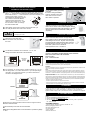
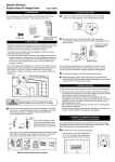
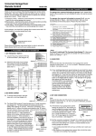
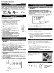
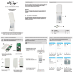
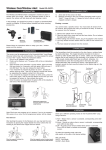
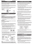
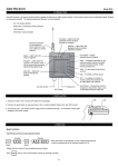
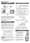
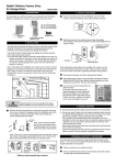
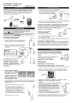
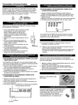
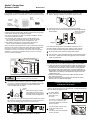
Skylink® Garage Door
Remote Control
Model 318TR
1. INTRODUCTION
2. INSTALLATION (CONT)
In this package, you will find a keychain transmitter with 12V alkaline battery,
a garage door receiver, a red / black wire, a mounting bracket and a clip.
Garage
Door
Receiver
Mounting
Bracket
Keychain
Transmitter
(Battery inside)
2 Plug in the connector end of the Red/Black wire to the 318R
receiver. Note the orientation of the male & female connector.
Clip
Red/Black Wire
2. INSTALLATION
3 Plug the receiver into an electrical outlet inside the garage.
The red light on the receiver should be on after being plugged into an
electrical outlet.
Existing wires connected
The following instructions will show you how to install the receiver. After
installing, the keychain transmitter (already programmed to the receiver)
can be used to operate your garage door opener.
to garage door opener.
(Do not remove)
You need to locate 2 things inside your garage to install the receiver:
1) the wall-mounted door control;
2) an electrical outlet, select an electrical outlet different from
the one already connected to the power cord of the garage
door opener to reduce the chance of interference. The
further distance between the receiver and the garage door
opener, the less interference between 2 devices.
Note: The length of the red/black wire is 20ft, so the receiver must be
plugged into an electrical outlet that is within 20ft of the wall mounted
door control. If there is no electrical outlet within 20ft of the wall
mounted door control, an extension cord can be used for temporary
installation. Longer wire is available, please contact our customer
service for further information.
RECEIVER
RED/BLACK WIRE
Note: Alternative wiring options are available, the receiver can be
connected directly to the opener’s motor. Please contact customer
service for further information regarding alternative wiring options.
4 Re-connect the power cord of the Garage Door Opener.
5 The Left button on the transmitter has been programmed to operate
the receiver. Activate this button will trigger the receiver therefore
opens the garage door.
Wall Mounted
Door Control
Remove power cord of garage
door opener before installation.
3. TROUBLE SHOOTING
Q: Door opener does not react after pressing the button on the transmitter ?
Electrical
Outlet
WARNING
1
Unplug the power cord of your garage door opener before
installation to ensure power is not connected.
Remove the wall-mounted door control from the wall by removing
the screws. Connect the stripped ends of the Red/Black wire to the
2 terminals (2 screws) on the back of the wall mounted door
control. (Polarity does not matter.)
Existing
wires
Note: There should be another
pair of wires connected to the 2
terminals already. Do not remove/
disconnect these existing wires.
Red /
Black wire
A: - Ensure when the button on the transmitter is pressed, the red light on the
transmitter comes on. Otherwise, check if the battery is inserted properly.
- The left button on the transmitter should be pressed, not the right button
- If the red light on the receiver flashes when you press the left button on
the transmitter, but the door opener does not respond, please ensure the
red/black wire is successfully connected from the receiver to the wall
mounted door control.
- Ensure the wires that are previously connected to the wall mounted
door control are not loose.
- Ensure the code setting on the transmitter is the same as the receiver.
Refer to section 4 to check the code setting.
4. CHANGE THE OPERATION CODE FOR BOTH
TRANSMITTER AND RECEIVER
It is recommended to randomly set the operation code for your remote
control to avoid interference from other devices. Follow the instructions
below to change the operation code.
1 Pry off the battery
cover of the transmitter with a coin,
as shown.
BATTERY
Note: If you see no screws mounting the wall mounted door control,
the screws are probably under-neath the front cover. Remove the
front cover by pressing onto the tabs on top of the cover.
You will see 9 connectors labeled
from “1” to “9”, as shown. (the
connectors setting may not be the
same as shown.)
2
Remove front
cover first
Different wall-mounted door controls
You can randomly remove some
connectors, leaving some
in place.
A connector can be removed with
the clip, as shown.
4. CHANGE THE OPERATION CODE FOR BOTH
TRANSMITTER AND RECEIVER (CONT)
3 If the connector is placed on the top and middle posts, that column is
set on “ + ” . If the connector is placed on the middle and bottom posts,
that column is set on “ - ”. If the connector is removed completely, (not
placed on any posts), it is set to “ 0 ”.
‘0’
(see diagram for examples of how to
set a column to the three different
positions). When removing a con‘+’
nector to set a column to “ 0 ”, save
‘-’
the connector in case you change
the code at a later date.
4 After setting up the code connectors on the transmitter, you
are ready to set the same code on the receiver.
WARNING
5. BATTERY
12 volt alkaline battery (size 23A)
(included).
It is time to change the battery
when the red LED on the transmitter does not turn on when
either button is pressed.
6. ADDITIONAL RECEIVER
There are 2 buttons on your transmitter, the other
button can be used to control another Skylink® Garage
Door Receiver Model 318R (sold separately) or Skylink®
Wireless Switch Receiver Model SW-318R (sold
separately).
Remove the receiver from the electrical outlet before
changing the code.
7. ADDITIONAL TRANSMITTER
You can add as many additional transmitters as you
want to control the same receiver. Simply set the
same operation code on all transmitters with the same
code setting on the receiver. Skylink® offers Keychain
Transmitter Model 318TN and Keyless Entry Transmitter Model 318K to work with your receiver. For more
information, please visit our website at
www.skylinkhome.com or contact us.
5 Remove the screw that holds
the connector cover, and remove
the cover.
8. CAUTION
6 You will see 10 connectors. For connec tors “1” to “9”, the
settings must match with those of the transmitter.
RISK OF ELECTRICAL SHOCK. FOR INDOOR USE ONLY.
CAUTION : DISCONNECT POWER BEFORE CODE CHANGING.
REPLACE COVER AFTER CODE CHANGING.
Maximum Rating:
Input : 120VAC 60Hz 2W
Connectors
1 to 9 are
the same.
9. FCC
BATTERY
This device complies with Part 15 of the FCC Rules. Operation is subject to the following two conditions:
(1) This device may not cause harmful interference, and (2) This device must accept any interference
received, including interference that may cause undesired operation.
7 For connector “10” on the receiver, set the connector on “+” if you
are using button “1” to control this receiver. If you are planning to
use button “2” to control this receiver, you need to remove this
connector. See diagram below.
WARNING:
Changes or modifications to this unit not expressly approved by the party responsible for compliance could
void the user’s authority to operate the equipment.
NOTE:
This equipment has been tested and found to comply with the limits for a Class B digital device, pursuant
to Part 15 of the FCC Rules. These limits are designed to provide reasonable protection against harmful
interference in a residential installation. This equipment generates, uses and can radiate radio frequency
energy and, if not installed and used in accordance with the instructions, may cause harmful interference
to radio communications.
However, there is no guarantee that interference will not occur in a particular installation. If this equipment does
cause harmful interference to radio or television reception, which can be determined by turning the equipment
off and on, the user is encouraged to try to correct the interference by one or more of the following measures:
Connector 10 set to “+”
TRANSMITTER
Button 1- Left Button
- Reorient or relocate the receiving antenna.
- Increase the separation between the equipment and receiver.
- Connect the equipment into an outlet on a circuit different from that to which the receiver is connected.
- Consult the dealer or an experienced radio/TV technician for help.
10. WARRANTY
RECEIVER
If, within one year from date of purchase, this product should become defective
(except battery), due to faulty workmanship or materials, it will be repaired or
replaced, without charge. Proof of purchase and a Return Authorization are required.
11. CUSTOMER SERVICE
Connector 10 “Removed”
TRANSMITTER
Button 2- Right button
RECEIVER
8 Put the cover and screw back onto the receiver. Plug the receiver
into an electrical outlet.
9 Put the battery cover back onto the transmitter.
10 Press the designated button on the transmitter to operate the garage
door.
If you would like to order Skylink’s products or have difficulty getting them to work,
please :
1. visit our FAQ website at www.skylinkhome.com , or
2. email us at [email protected] , or
3. call our toll free at 1-800-304-1187 from Monday to Friday, 9 am to 5 pm EST.
Fax (800) 286-1320
CUSTOMER SERVICE
17 Sheard Avenue, Brampton, Ontario, Canada L6Y 1J3
Email:[email protected]
http://www.skylinkhome.com
P/N. 101A206-005 Rev.5
US Patent. D380895
©2005 SKYLINK GROUP