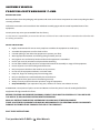
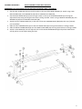
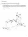
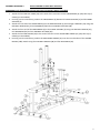
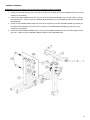
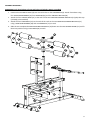
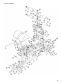
1
OWNER’S MANUAL F-GHR Glute Ham Raise CAUTION! Read all precautions and instructions in this manual before using this equipment. 1 ASSEMBLY MANUAL FORCE USA GLUTE HAM RAISE F-GHR BEFORE YOU START Remove all parts from the packaging and separate and count each various component to ensure everything has been correctly provided. Follow the instructions and consult both the individual assembly pages and the overall expanded views of the equipment. Certain parts may arrive pre-assembled from the factory. It is the owner’s responsibility to ensure that all users of this unit have read the owner’s manual and are familiar with the safety precautions. SAFETY PRECAUTIONS • • • • • • • • • • • • • • • Highly recommended for two or more people to assemble the equipment to avoid injury. Assemble the equipment on a flat level surface. Consider placing a mat under the equipment to protect your floor. Wear appropriate footwear and clothing during assembly and use. Only tighten nuts and bolts by hand until the whole equipment is assembled Ensure you correctly orientate each piece before attaching Do not allow children and pets to be unsupervised around the assembly or usage of this equipment. Ensure all parts are in full working order before use. Only one person should use the machine at any one time. Do not use the equipment outdoors or around water. Keep hair, fingers or clothing away from moving parts. Only use attachments recommended by the manufacturer. Never operate if any parts are not functioning correctly. Always correctly stretch and warm up before using the equipment. Stop immediately if your experience any pain, dizziness or nausea. See a doctor at once. PLEASE NOTE: Descriptions of pieces as LEFT and RIGHT are from the point of view of standing behind the equipment facing towards the front. BEFORE STARTING ANY EXERCISE PROGRAM, CONSULT YOUR DOCTOR. ESPECIALLY IF YOU ARE OVER THE AGE OF 35 OR HAVE PRE-EXISTING HEALTH PROBLEMS. READ ALL INSTRUCTIONS BEFORE ASSEMBLING OR USING ANY FITNESS EQUIPMENT. FORCE USA FITNESS EQUIPMENT ASSUMES NO RESPONSIBILITY FOR PERSONAL INJURY OR PROPERTY DAMAGE SUSTAINED BY OR THROUGH THE USE OF THIS PRODUCT. SAVE THESE INSTRUCTIONS. Tool provided with F-GHR = Allen Wrench 2 KEY NO. DESCRIPTION Main Base Frame Front Stabilizer Rear Stabilizer Front Support Rear Support Cross Brace Left Sliding Block Right Sliding Block Left Guide Rod Right Guide Rod Adjustable Frame Foam Adjustment Bracket Pad Support Frame Foot Frame Weight Post Foot Plate Foam Baffle Bracket Bracket Spring Clip Wheel End Cap Lock Knob End Cap End Cap End Cap Sleeve Handle Grip Pad End Cap Foam Roll End Cap Carriage Bolt Carriage Bolt Carriage Bolt Hex Bolt Sunk Screw Hex Bolt Sunk Screw Allen Bolt Allen Bolt Hex Bolt Aircraft Nut Washer Washer Aircraft Nut SPEC ƶhh ƶhh hh h hh hh ¶hh¶ ƶh 0h¶ ƶ ƶ ¶ ƶhƶ ¶h hh ƶh ¶h¶h ƶ 0h 0h 0h 0h 0h 0h 0h 0h 0h 0h 0 0 Q'TY 3 ASSEMBLY DIAGRAM 1 REMEMBER: Only hand tighten all nuts and bolts until whole F-GHR is assembled Attach the two END CAP50 (25) to the ends of the cross bar on the REAR SUPPORT (5) (Skip this step if already pre-assembled) 2. Ensuring correct orientation, position the REAR SUPPORT (5) over the central bolt holes on the REAR STABILIZER (3) 3. Ensuring the MAIN BASE FRAME (1) is correctly orientated, with the side bolt holes towards the front of the F-GHR, align the rear end of the MAIN BASE FRAME (1) with the base of the REAR SUPPORT (5) Attach through the REAR SUPPORT (5) and the REAR STABILIZER (3) using two CARRIAGE BOLT M10X75 (33), two WASHER10 (44) and two AIRCRAFT NUT M10 (46) 4. Attach the front end of the MAIN BASE FRAME (1) to the FRONT STABILIZER (2) and through a BRACKET (18), using two CARRIAGE BOLT M10X70 (34), two WASHER10 (44) and two AIRCRAFT NUT M10 (46) 1. 4 ASSEMBLY DIAGRAM 2 USE A PARTNER TO HELP WITH THIS STEP REMEMBER: Only hand tighten all nuts and bolts until whole F-GHR is assembled 1. Slot the LEFT GUIDE ROD (9) over the left socket on the top of the REAR SUPPORT (5) Attach using a HEX BOLT M10X60 (36), two WASHER 10 (44) and an AIRCRAFT NUT M10 (46) 2. Slot the RIGHT GUIDE ROD (10) over the right socket on the top of the REAR SUPPORT (5) ensuring the adjustment holes along the length of the rod are facing outward. Attach using a HEX BOLT M10X60 (36), two WASHER 10 (44) and an AIRCRAFT NUT M10 (46) 3. Attach the four SLEEVES 50X45 (27) to the ends of the two SLIDING BLOCKS (7&8) (Skip this step if already pre-assembled) 4. Slide the LEFT SLIDING BLOCK (7) onto the LEFT GUIDE ROD (9) ensuring the brackets are facing inwards. 5. Slide the RIGHT SLIDING BLOCK (8) onto the RIGHT GUIDE ROD (10) ensuring the brackets are facing inwards. 6. Attach a LOCK KNOB (23) into the adjuster hole on the RIGHT SLIDING BLOCK (8) and position both blocks side by side at a central point along the rods. 5 ASSEMBLY DIAGRAM 3 REMEMBER: Only hand tighten all nuts and bolts until whole F-GHR is assembled Attach the two END CAP45 (24) to the ends of the cross bars on the FRONT SUPPORT (4) (Skip this step if already pre-assembled) 2. Position the FRONT SUPPORT (4) so that the base is in line with the bolt holes on the MAIN BASE FRAME (1) and the brackets slot into the ends of the GUIDE RODS (9&10) 3. Attach to the MAIN BASE FRAME (1) using two CARRIAGE BOLT M10X70 (34), two WASHER10 (44) and two AIRCRAFT NUT M10 (46) 4. Attach to the GUIDE RODS (9&10) using a HEX BOLT M10X60 (36), two WASHER10 (44) and an AIRCRAFT NUT M10 (46) on each rod. 1. 6 ASSEMBLY DIAGRAM 4 USE A PARTNER TO HELP WITH THIS STEP REMEMBER: Only hand tighten all nuts and bolts until whole F-GHR is assembled 1. 2. 3. 4. 5. 6. Attach the four END CAP 25X50 (22) to the ends of the cross bars on the CROSS BRACE (6) (Skip this step if already pre-assembled) Ensuring correct orientation, position the CROSS BRACE (6) between the REAR SUPPORT (5) and the FRONT SUPPORT (4) Attach the rear end of the CROSS BRACE (6) to the REAR SUPPORT (5) and through a BRACKET (19) using two HEX BOLT M10X70 (42), three WASHER10 (44) and one AIRCRAFT NUT M10 (46) Attach the front end of the CROSS BRACE (6) to the FRONT SUPPORT (4) using one HEX BOLT M10X70 (42), two WASHER10 (44) and one AIRCRAFT NUT M10 (46) Attach the four END CAPS45 (24) to the ends of the bars on the ADJUSTABLE FRAME (11) (Skip this step if already pre-assembled) Ensuring correct orientation, position the ADJUSTABLE FRAME (11) over the inner brackets of the SLIDING BLOCKS (7&8) Attach using four HEX BOLT M10X16 (38) and four WASHER10 (44) 7 ASSEMBLY DIAGRAM 5 REMEMBER: Only hand tighten all nuts and bolts until whole F-GHR is assembled Attach the four END CAP32 (32) to the ends of the bars on the back of the FOOT FRAME (14) (Skip this step if already pre-assembled) 2. Position the FOOT FRAME (14) on the rear post of the ADJUSTABLE FRAME (11) so the flat surface is facing towards the front. Attach using two CARRIAGE BOLT M10X65 (35), two WASHER10 (44) and two AIRCRAFT NUT M10 (46) 3. Attach the two HANDLE GRIPS (28) to the ends of the handles on the PAD SUPPORT FRAME (13) Attach the two END CAP 25X70 (30) to the ends of the crossbar on the PAD SUPPORT FRAME (13) (Skip this step if already pre-assembled) 4. Position the PAD SUPPORT FRAME (13) on the top of the FRONT SUPPORT (4) so the handles angle towards the front. Attach using four HEX BOLT M10X16 (38) and four WASHER10 (44) 1. 8 ASSEMBLY DIAGRAM 6 REMEMBER: Only hand tighten all nuts and bolts until whole F-GHR is assembled Position the two FOOT PLATES (16) over the bolt holes on the CROSS BRACE (6) Attach from above using four SUNK SCREWS M8X65 (37) four WASHER8 (45) and four AIRCRAFT NUT M8 (43) 2. Attach the four SLEEVES 50X45 (27) to the ends of the two FOAM ADJUSTMENT BRACKETS (12) (Skip this step if already pre-assembled) 3. Attach the four FOAM ROLLS (31) to the ends of the rods on the two FOAM ADJUSTMENT BRACKETS (12) using a SUNK SCREW M8X30 (39) and a FOAM BAFFLE (17) on each. 4. Slide the two completed FOAM ADJUSTMENT BRACKETS (12) down onto the ADJUSTABLE FRAME (11) and fix them into position using a LOCK KNOB (23) on each. 1. 9 ASSEMBLY DIAGRAM 7 REMEMBER: Only hand tighten all nuts and bolts until whole F-GHR is assembled Attach the four END CAP25 (26) into the ends of the two WEIGHT POSTS (15) (Skip this step if already preassembled) 2. Slide the two WEIGHT POSTS (15) into a hole on each side of the FRONT STABILIZER (2) and attach a SPRING CLIP (20) to each post. 3. Ensuring correct orientation, position the two PADS (29) on top of the PAD SUPPORT FRAME (13) and attach using four ALLEN BOLT M8X20 (40) and four WASHER8 (45) 1. 10 EXPLODED DIAGRAM 11 12 0h+H[%ROW4W\ 0h+H[%ROW4W\ PP ¦ ¦ ¦ ¦ ¦ ¦/852 13 WARRANTY LIFETIME WARRANTY ON FRAME 2 YEAR WARRANTY ON MOVING PARTS (Such as cables and pulleys) Force USA, the Trusted Name in Strength Equipment™ was designed to be the best value strength equipment for home use and proudly set the benchmark for our home use equipment around the world. Offering one of the best warranties on the market for your peace of mind, each piece of Force USA strength equipment is hand crafted for quality and we use state-of-the-art production methods for our entire range. The Force USA range of strength equipment carries a Lifetime Structural Warranty along with 2 years cover on all cables and pulleys. This warranty applies to first owners and does not cover second hand equipment or re-sold equipment. This Force USA warranty covers only failures due to defects in structural, cables and pulleys and workmanship that occur during normal home use. It will not cover damage that occurs in transport/delivery or failure due to misuse, abuse, neglect, mis-application, alteration or improper assembly of the product. This warranty does not cover the use or failure of equipment in studio commercial applications. The replacement or repair provided for under the Force USA warranty is the responsibility of the user and the customer will be responsible for any freight charges applicable. Force USA will not be liable for any consequential damages or for breach of any implied warranty on the range of Force USA strength equipment. Force USA reserves the right to provide reconditioned parts and/or to request a return and repair existing defective parts on the Force USA product. VorTex by Force USA is a commercial grade upholstery used for all Force USA equipment. We use a high grade commercial vinyl with rip-stop mesh backing which helps prevent rips and tears. Force USA, the Trusted Name in Strength Equipment™ was designed to be the best value strength equipment for home use and proudly set the benchmark for our home use equipment around the world. 14 F-GHR Box one˖ 1×part 14ˈ 1x part 6ˈ 2×part 16ˈ 1×part 9ˈ 1×part 10ˈ 1×part 7ˈ 1x part 8ˈ 1×part 1ˈ 1×part 2ˈ 1×part 11ˈ 1×part 3ˈ 2x part 12ˈ 2×part 15ˈ 1×part 5ˈ 1×part 4ˈ 3×part 23ˈ 1x part 18ˈ 1×part 19ˈ 4×part 17ˈ1×part 13ˈ Parts bag 1of 2ˈParts bag 2of 2 Box two˖ 2×part 29ˈ 4x part 31