1
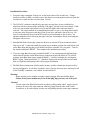
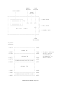
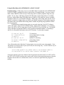
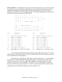
Blue Ram Owner's Manual
Perkins Engineering
1004 Pleasant Avenue
Boyne City, MI 49712
Copyright 1982
Blue Ram Owner's Manual
Version 1.1 - Released Oct 15, 2000
This document has been retyped and converted to PDF format courtesy of the Bally Alley newsletter. For other reprints and more
information visit: http://www.ballyalley.com Corrections? Suggestions? Email Adam Trionfo at: [email protected]
Blue Ram Operations.
General.
The Blue Ram contains the following features:
1. 16384 (16K) bytes of read-write random access memory (RAM) which can be write
protected either manually or under Program control. This memory is in addition to the 4096
(4K) bytes of screen RAM built into the Arcade. The memory expansion option adds another
16384 bytes for a total of 32768 (32K) bytes of RAM. This memory is located at %(245765)
or 6000 (hex). Note that ASTROBASIC treats negative memory addresses as references to
screen memory making it impossible to access more than the first 8K of Blue Ram memory
using that cartridge. Use Blue Ram BASIC for full memory access.
2. 128 bytes of additional scratch pad memory which cannot be protected from write
operations,. This memory is located at %(-24576) or A000 (hex) in a 16K Blue Ram and at
%(-8192) or E000 (hex) in a 32K Blue Ram. Note that ASTROBASIC treats negative
memory addresses as references to screen memory making it impossible to access this Blue
Ram memory area using that cartridge. Use Blue Ram BASIC for full memory access.
3. A RANGE switch to allocate the first 8192 (8k) bytes of RAM to either 6000 (hex) for
normal use or 2000 (hex) for game cartridge emulation. In the latter position the RAM acts
as if it were a cartridge plugged into the front of the Arcade and running a machine-code
Program.
4. Two eight-line bi-directional I/O Ports (PORT A and PORT B) where any line or
combination of lines may be in either port may be assigned as input or output lines under
Program control. I/O lines may be reconfigured at will under program control, by operating
several control resisters within the Blue Ram.
5. External Power and ground (+5v and 0v) available for powering additional low power
(<0.5A) applications. The internal power supply has thermal protection against overloads
which results in the temporary loss of power should an overload exist.
6. Special Ports available for AUDIO-MIX, CPU CLOCK, I/O OPERATION SYNC, and I/O
WAIT SYNC for expansion to (future) devices such as floppy disks and voice synthesis.
7. All external connections to the Blue Ram are made via a 24 Pin zero-insertion-force (ZIF)
socket for easy access. This type of socket can accommodate 24 Pin Plugs, component leads,
and bare wire ends directly without risk of bending.
8. 2 2000 BAUD tape ports for use with Blue Ram BASIC. One Port (MIC) is used for saving
programs and data using Blue Ram BASIC. The other Port (EAR) is used to reload
programs and data saved using Blue Ram BASIC. These Ports operate only in conjunction
with Blue Ram BASIC. Use the tape interface jack (on the cartridge or tape interface) when
operating with ASTROSASIC or BALLY BASIC.
Blue Ram User's Manual - Page 1 of 8
Installation Procedure.
1. Locate the long rectangular "knock-out" on the back center of the Arcade case. Using a
small screwdriver or knife, carefully remove this knock-out ensuring that you do not poke the
screwdriver or knife into the case more than 1/4 inch.
2. The 50 Pin PC connector exposed in the previous step may have its access blocked or
interfered with by a portion of the insulating "fish paper" just below the circuit board. If this
is the case, the portion which blocks access to the full depth of the connector must be
removed. The easiest method of accomplishing this task is to use a very sharp Exacto knife
to cut parts in the fish paper at the edge of the access hole, and bend it out of the way. Be
sure to cut downward (away from the PC board) to prevent damage to the circuitry. An
alternate method involves removing the upper case part, loosening the board, and cutting the
fish paper with scissors.
3. Push the Blue Ram 50-pin edge connector all the way onto the PC board connector until a
firm stop is felt. Connect the small plug on the power module cord into the small (front) jack
on the Blue Ram and plug the power module itself into a suitable 120v receptacle. Turn on
the Arcade and depress RESET. This completes the installation procedure.
4. If you are using Blue Ram (super extended) BASIC 1.1 in conjunction with the Blue Ram,
ensure that all switches on the Blue Ram are in their back-part (6K RAM AUTO LOAD)
position, insert Blue Ram (super extended) BASIC 1.1 into the cartridge slot, and depress
RESET again. "Blue Ram BASIC 1.1" should be displayed at the top of the screen in dark
blue on a light blue background, this verifies proper installation.
5. The Blue Ram contains non-volatile (static) memory and the contents may be preserved by
leaving it plugged in. It will draw less than 5 watts of power when not in use and may be left
in this "standby" condition, even with the Arcade turned off.
Warning!
Ensure that the power module cord plug remains plugged fully into the Blue Ram!
Failure of the power module may occur if that plug slips part way out of the jack!
Caution!
Do not remove the Blue Ram from the Arcade by pulling on the cable! Apply removal
pressure directly to the edge connector either by prying from the sides with a small
screwdriver or by removing the Arcade case and pushing directly on the edge connector.
Blue Ram User's Manual - Page 2 of 8
Switch Settings. There are three switches on the Blue Ram for control of memory range,
memory write Protection, and the 2000 BAUD tape interface.
1. Range Switch: The RANGE switch is used to allocate Blue Ram memory to a
particular starting location or address and has two positions. The 6K-RAM position
is the normal position for this switch and allocates the starting address of Blue Ram
memory to 24576 (or 6000 hex ). For example, PRINT %(24576) prints the contents
of the first word of Blue Ram memory. (Note that the line number of the first line of
a Blue Ram BASIC program normally occupies this word.) The 2K-CASS position
of the RANGE switch allocates the first 8K of memory so that it displaces the
cartridge (if any) which is plugged into the cassette slot on the front of the Arcade.
The only use of this Position is to emulate a game cartridge by running a
machine-code program similar to those in the regular game cartridges. Future issues
of the Arcadian will explore this feature further. Also, see the Customize A Game
Cartridge feature of the Blue Ram Utility.
2. Mode Switch: The mode switch is used to control memory protection and has three
positions. The AUTO position is the normal position for this switch and allows
memory protection to be controlled by a program. (See &(64) and &(192) in the
INPUT/OUTPUT section). The RAM (center) position disables memory write
protection even if it was enabled by a program. Similarly, the ROM position prevents
all writes to memory, except scratch-pad memory, regardless of any program
instructions to the contrary.
3. Tape Switch: The TAPE switch controls the 2000 BAUD tape interface and has two
positions. The LOAD position is the normal position of this switch and allows 2000
BAUD programs previously saved using Blue Ram BASIC to be loaded back into the
Blue Ram using the same Blue Ram BASIC. With the TAPE switch in this Position,
line 0 of PORT B is internally connected to the tape interface and may not be used for
other devices. However, with the TAPE switch in this Position, 2000 BAUD tapes
May be duplicated by playing the master tape from one recorder using the EAR
connection, while recording the duplicate on another recorder using the MIC
connection. The 2000 BAUD interface will control the record level and the wave
shape of the duplicate, offering enhanced data fidelity in many cases. The SAVE
position is used in conjunction with Blue Ram BASIC to save programs and data on
tape at 2000 BAUD. This switch position is also used when it is necessary to use line
0 of PORT B for other than tape input. The TAPE indicator light is permanently
connected to line 0 of PORT B and may thus be lit under program control. For
example, &(163)=1;&(152)=0 will light the TAPE light when the TAPE switch is in
the SAVE position.
Blue Ram User's Manual - Page 3 of 8
RANGE
TAPE
SWITCH
SWITCH
ZIF SOCKET
|
|
|
|
MODE |
|
| SWITCH |
|
|
|
|
+----------|---------------|----|----|----+
|
|
|
|
|
|]
|
+------|--------+
|
|
|
|] ---EAR JACK
|
| [[[[[[[[[[[[ |=()
|
|
|
|]
|
|
|
(0) (0) (0)
|
|
| [[[[[[[[[[[[ |
|]
|
+---------------+
|] ---MIC JACK
|
(0)
|]
|
B L U E
R A M
|
|
|
|
|] ---POWER JACK
|
|
|]
|
|
|
+------------------------------------|----+
|
|
TAPE
INDICATOR
Decimal
address
24576
32767
-32768
-24577
-24576
-24449
-8193
-8192
-8065
+--------------------------+
|
|
|
LOWER 8K
|
|
|
+--------------------------+
|
|
|
SECOND 8K
|
|
|
+--------------------------+
| SCRATCH-PAD FOR 16k SIZE |
+--------------------------+
|
|
|
|
|
SECOND 16k
|
|
|
|
|
|
|
+--------------------------+
| SCRATCH-PAD FOR 32K SIZE |
+--------------------------+
6000
7FFF
8000
9FFF
A000
A07F
DFFF
E000
E07F
Blue Ram User's Manual - Page 4 of 8
- highest address
which can be
accessed by
ASTROBASIC or
BALLY BASIC
Using the Blue Ram with ASTROBASIC or BALLY BASIC
Extended strings. Of the many ways to use the Blue Ram in conjunction with ASTROBASIC
or BALLY BASIC, probably the easiest is in the form of extended strings. As you are aware,
either of these BASICs will access up to.900 string entries (with no program) using the @(n)
symbol. If you write a 1000 byte program (SZ=800) then on 400 string entries are available.
However, with the Blue Ram 8256 string entries (16448 for 32K option) are always available,
regardless of the size of your BASIC Program. What's more, these string entries do not "move
around" or otherwise change when you modify your BASIC program or load another program.
This makes these special Blue Ram string entries valuable for passing large quantities of data
between programs.
The Blue Ram extended string entries are accessed using the %(2n+24576) form to
"poke" and "peek" values into the extended strings. String entry #0 therefore, is at %(24576)
(since 2x0+24576=24576), string entry #1 is at %(24578), #2 is at %(24580), etc. The MODE
switch should be in either the RAM or AUTO position with RAM enabled. Performing a
&(192)=0 will enable RAM mode in the AUTO Position. Try this short example:
10
20
30
40
50
60
FOR N=1 TO 25
%(2xN+24576)=N
NEXT N
FOR M=1 TO 25
PRINT %(2Xm+24576)
NEXT M
25 count loop
stores string number in string
completes loop
another 25 count loop
prints string content
completes loop
You will note that each of the first 25 string entries were set to their own string number. Note
also that the 2x term provides 2 bytes (one word) for each string entry. A more efficient way of
writing the same program is:
10 N=1;FOR A=24578 TO 24626 STEP 2;%(A)=N;N=N+1;NEXT A
20 FOR M=24578 TO 24626 STEP 2;PRINT %(M);NEXT M
A Program will always be more efficient if the Programmer does the math (2x1+24576=24578
and 2x25+24576=24626) and uses the results as the values in the program statements so that the
computer does not have to calculate those values over and over again when the program is
running.
Blue Ram User's Manual - Page 5 of 8
INPUT/OUTPUT. The Blue Ram contains two 8-line bi-directional I/O ports. The first 8 lines
are referred to as port A while the second 8 lines are referred to as port B. Either port may be
configured with any line or combination of lines being in the INPUT mode (for receiving
signals) or the OUTPUT mode (for sending signals). The following diagram shows the location
of each line of each port on the 24 Pin ZIF socket:
12 11 10 9 8 7 6 5 4 3 2 1
+---------------------------------------+
| A C + 0 1 2 3 4 5 6 7 G
| |==( )
| U L 5
N
--|
| D K v ---- PORT A LINES ---- D
|
|
|
|
|
| G ---- PORT B LINES ---- + - |
| N
5 W I
|
| D 7 6 5 4 3 2 1 0 v T O
|
+---------------------------------------+
13 14 15 16 17 18 19 20 21 22 23 24
PIN
--1
2
3
4
5
6
7
8
9
10
11
12
FUNCTION
-------Ground return for PORT A
Line 7 of PORT A
Line 6 of PORT A
Line 5 of PORT A
Line 4 of PORT A
Line 3 of PORT A
Line 2 of PORT A
Line 1 of PORT A
Line 0 of PORT A
+5v source for PORT A
Z80 CLOCK for external sync
AUDIO-MIX to add or tap sound
PIN
--13
14
15
16
17
18
19
20
21
22
23
24
FUNCTION
-------Ground return for PORT B
Line 7 of PORT B
Line 6 of PORT B
Line 5 of PORT B
Line 4 of PORT B
Line 3 of PORT B
Line 2 of PORT B
Line 1 of PORT B
Line 0 of PORT B *
+5v source for PORT B
WAIT(N) for external sync
IOREQ(N) for external sync
*Also connected to 2000 BAUD tape interface monitor light and is held at Ov when the
TAPE switch is in the LOAD position. Place the TAPE switch in the SAVE position to use the
line (with indicator) for other purposes.
The audio mixer (AUD) port accepts and/or provides a 1000-ohm +/- 2v audio signal to
be mixed with or extracted from the Arcade sound system. This port may be used to extract
sound from the Arcade to feed into a high fidelity amplifier or to add sound such as a tape
recorder voice-track or a voice synthesizer. The CLK, -WT, and -IO signals are connected
directly to the Z80 microprocessor (pins 6, 24, and 20 respectively) and will be used for circuit
synchronization in future Blue Ram add-ons such as disk drives, etc.
Blue Ram User's Manual - Page 6 of 8
Program control of the I/O ports is accomplished in BASIC via the &(n) term where n is an I/O
port number from the following table:
Read
x=&(n)
Write
&(n)=x
162
Function
Configures PORT A lines to be INPUT lines or OUTPUT lines
accordion to the value written to &(162). Each line is an INPUT
line unless it is programmed as an OUTPUT line by setting its
corresponding bit value into &(162):
line 0 =
line 3 =
line 6 =
163
160
160
161
161
128
128
129
through
135
136
through
143
144
129
through
135
136
through
143
144
145
through
151
145
through
151
1
8
64
line 1 =
2
line 4 = 16
line 7 = 128
line 2 =
line 5 =
4
32
Example: To allocate PORT A lines 0, 1, 5, and 7 as OUTPUT lines
- &(162)=1+2+32+128
or &(162)=163
Configures PORT B lines to be INPUT lines or OUTPUT lines
according to the value written to &(163) as with &(162) above.
Accesses PORT A for data transfers to and from devices connected
to PORT A. INPUT lines held high (>0,6v) during a read operation
result in their corresponding bit value being read from &(160). A
write operation to 60 causes the corresponding OUTPUT lines to be
set as indicated by the value written to &(160). Example:
To set all even OUTPUT lines of PORT A high (>3.2v) -&(160)=1+4+16+64 or &(160)=85. To verify this -- PRINT &(160)
NOTE: Outputs may read back as inputs.
Accesses PORT B for data transfers to and from devices connected
to PORT B as with &(160) above.
Accesses line 0 of PORT A individually. If line 0 is held high
during a read operation, a value of 128 is read; otherwise the value is
0. If line 0 of PORT A is allocated as an OUTPUT line, any value
written to &(128) will cause line 0 of PORT A to be reset low
(<0.6v) without affecting any other line.
Same as &(128) except that it applies to lines 1 through 7 of PORT
A respectively.
Same as &(128) except that it applies to lines 0 through 7 of PORT
B respectively.
Same as &(128) except that any value written to &(144) will cause
line 0 of PORT A to be set high (>3.2v) without affecting any other
line.
Same as &(144) except that it applies to lines 1 through 7 of PORT
A respectively.
Blue Ram User's Manual - Page 7 of 8
Read
x=&(n)
152
through
159
Write
&(n)=x
152
through
159
164
64
64
192
192
Note:
Function
Same as &(144) except that it applies to lines 0 through 7 of PORT
B respectively.
A write operation to &(164) sets the overall operating mode of the
I/O lines of PORT A and PORT B. Writing a value of 0 allows
independent operation of all lines of both ports. This is the normal
mode placed in effect by a RESET switch depression on the
Arcade. &(164)=32 causes the strobed input mode to be activated
whereby PORT A input data is latched as line 7 of PORT B goes
low. Line 6 of PORT B (OUTPUT) is brought low until the
program reads PORT A, indicating that the INPUT data is being
held in the Blue Ram. &(164)=96 causes the strobed output mode
to be activated whereby line 6 of PORT B (OUTPUT) is brought
low to indicate new data has been written to PORT A and is waiting
for the device to accept it. The device brings line 7 of PORT B low
to indicate that it has accepted the PORT A OUTPUT data and that
the next output may now be written to PORT A. &(164)=224
causes a mode to be activated which is similar to &(164)=96 except
that the OUTPUT data on PORT A lines only appears while line 7
of PORT B is held low by the external device. &(164)=0 resets the
mode to independent operation of all port lines.
Any operation with &(64) sets the memory mode to ROM when the
MODE switch is in the AUTO position
Any operation with &(192) sets the memory mode to RAM when
the MODE switch is in the AUTO position.
Output lines will only supply 2ma. of current. Do not expect them to drive heavy
loads. Use small relays or other amplifiers where more power is required.
Warning! Warning! Warning! Warning! Warning! Warning! Warning! Warning! Warning!
Do not connect A.C. appliances directly to the Blue Ram I/O ports! Never connect power from a
120v socket directly to any part of your Arcade or the Blue Ram or severe damage and shock
hazard will result!!! Relays or optical isolators with at least 1500v isolation should be used for
controlling 120v A.C. appliances.
Blue Ram User's Manual - Page 8 of 8