1
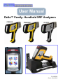
User Manual
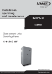
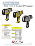
Delta™ Family: Handheld XRF Analyzers
PREMIUM
STANDARD
CLASSIC
Innov-X Systems, Inc.
100 Sylvan St.
Woburn, MA 01801 USA
PN_103201
Rev_A: June/2010
General
This Manual is solely the property of Innov-X Systems, Inc. and, along with the Delta™ XRF analyzer to which it applies, is provided for the exclusive use of Innov-X clients under contractual
agreement for Innov-X test and analysis equipment and services.
In no event does Innov-X Systems, Inc. assume the liability for any technical or editorial errors of
commission or omission; nor is Innov-X liable for direct, indirect, incidental, or consequential
damages arising out of the inability to use this Manual.
Government Restricted Rights Legend
Use, Duplication, or Disclosure by the US Government is subject to restrictions as set forth in
subparagraphs (c) (1) and (c) (2) of the Commercial Computer Software - Restricted Rights
Clause at FAR 52.227-19.
Copyright
This Manual is protected by copyright, all rights reserved. No part of this book shall be reproduced, stored in a retrieval system, or transmitted by any means, electronic, mechanical, photocopying, recording, or otherwise without written permission from the Innov-X Systems, Inc.
Trademarks
Innov-X, the Innov-X logo, Delta, Delta Docking Station, and Delta TestStand/Workstation are
trademarks of Innov-X Systems, Inc.
Microsoft, Windows, Windows XP, and Windows CE are registered trademarks of Microsoft Corporation in the United States and/or other countries.
All other products, companies, or service trademarks mentioned herein are the property of their
respective owners.
Changes
Material in this Manual is for information only and is subject to change without notice. While
reasonable efforts have been made in the preparation of this document to assure its accuracy,
Innov-X assumes no liability from errors or omissions in this document, or from the use of the
information contained herein.
Innov-X Systems, Inc. reserves the right to make changes in the product design without reservation and without notification to its users.
Revision History
Release Date for this document and its individual sections is June, 2010. This enters the
Innov-X document control system as Revision A
The material is available as Adobe PDF-type files. Distribution of the files or hard-copy representations is at the discretion of Innov-X Systems, Inc.
GO TO
See “A7. Legal Information” for information concerning Innov-X Systems, Inc.’s warranties, licenses, and liabilities.
Copyright© 2005-2010.
By Innov-X Systems, Inc.
All Rights Reserved
Delta ™Family Handheld XRF Analyzers
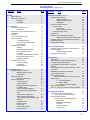
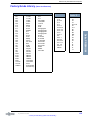
CONTENTS - Page 1 of 3
SECTION.........TOPIC......................................................PAGE
Preface
Manual Structure
Document Conventions
Messages
Type Styles
7
7
9
10
10
C1. Introduction
Description of Delta System
Applications
Delta Family: Types, Models, Modes and
Calibrations
Inspection
Tour of the Delta Carry Case
Tour of Instrument
1. Handheld Analyzer
2. Delta Docking Station (DDS)
3. AccessoriesSTANDARD Accessories
Batteries
Delta Docking Station (DDS)
Power Adapter for DDS
I/O Cables
Cal_Check (Standardization) Coupon
Measurement Window Films
Application Software
OPTIONAL Accessories
AC Power Adapter
PC Software
XRF Workstation
11
11
11
12
C2. Safety Information
Radiation Safety Information
Radiation Safety Program
X-Ray Safety
General Precautions
Service Considerations
Electrical Precautions
Cables and Cords
Cable Guidelines
Delta Docking Station (DDS) and Li
ion Battery Packs
Indicator and Warning Lights
Power Switch w/ Integral Indicator
Light
X-Ray Indicator Light Array
X-Ray Indicator ON (Blinking)
X-Ray Indicator ON Continuously (Not
Blinking)
Proximity Sensor
Back of Analyzer
X-Ray Label
Other Safety Features
Proximity Sensor
13
14
15
15
16
17
17
17
17
18
18
19
19
19
20
20
20
20
21
21
22
22
22
23
23
24
24
24
25
25
25
26
26
26
26
27
27
27
SECTION.........TOPIC...................................................PAGE
C2. Safety Information, Continued
Safety Interlock Structure
Software Trigger Lock
Software Proximity Sensor
Safeguards
Instrument Usage Scenarios
......Correct Usage
Test in Place
Small Component Testing
.....Incorrect (Unsafe) Usage
Compliance
Radiation Doses for Several Scenarios
Radiation Doses from Typical Exposures
Radiation Safety: Common Questions & Answers
Analyzer Shut Down
Delta Radiation Profile
28
28
28
28
29
29
29
29
31
32
32
34
35
36
37
C3. Safety Administration
Radiation Safety Training Recommendations 39
Dosimeter Badges
Dosimeter Safety Program
Registration Requirements
39
39
40
41
42
C4. Operations
Safety First !
Set Up and Use the Delta Docking Station
Configure Delta Docking Station
Use the Delta Docking Station for Charging
Batteries
Use the Delta Docking Station for Startup - Initial
Cal Check
SNAPSHOT of Delta’s User Interface
Typical Test Procedure
End of Day Operations
........DATA connection between analyzer and PC
Battery Issues
1 — Changing a Battery
2 — Battery Status
3 — HOT SWAP for Delta Battery
Cal_Check Information
TIPS - or - things you should know about the Delta
43
43
43
44
45
C5. Alloy Analysis Modes
Introduction to Alloy Analysis Modes
...........Alloy, Alloy Plus, FastID, Pass/Fail,
Precious Metals Additions
..........Determination of Grade Identification:
Match Issues
Grade Match Messaging
SmartSort
Nominal Chemistry
Tramp Library
53
53
46
47
48
49
49
50
50
50
50
51
52
54
55
56
56
57
57
3
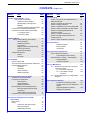
CONTENTS - Page 2 of 3
CONTENTS - Page 2 of 3
SECTION.........TOPIC...............................................PAGE
SECTION.........TOPIC.................................................PAGE
C5. Alloy Analysis Modes, Continued
........Test Sample Considerations
Coated or Painted Samples
Mixed Samples, Heterogeneous
Materials
Small and Irregularly Shaped Samples
Introduction to FastID Mode (All Models)
Introduction to Pass/Fail Mode (All Models)
1. Fingerprint Option
2. Chemistry Option
A2. Soil Testing
Section 1: Commonly Accepted Methods for
Field Portable XRF
Section 2: Overview of Field Usage:
Section 3: Quality Assurance
Section 4: Calibration for Innov-X Portable XRF
Section 5: Effects of Moisture on XRF Results
Section 6: Comparing XRF Results to
Laboratory Results
Section 7: Common Interferences
Section 8: Sample Prep Procedures and
Testing Protocols
Section 9: NIST Certificates of Analysis
79
79
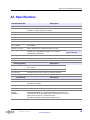
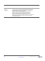
A3. Specifications
Handheld Analyzer
Docking Station
Accessories
95
95
95
96
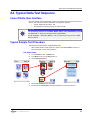
A4. Typical Delta Test Sequence
Innov-X Delta User Interface
Typical Sample Test Procedure
Best Practices for Testing -- Various Modes
Check Standards
Sample Presentation
97
97
97
99
99
100
A5. User Maintenance
5.1 — Alternative Techniques for Powering or
...........Charging the Delta
5.1.1. AC Power Adapter Kit
5.1.2. Li ion Battery Charger
..........Assembly
5.2 — Window Replacement for “Hinged Plate”
..........Analyzers
101
101
A6. Packing and Shipping
Instructions for Obtaining a RMA
Contact Points for Innovx Offices and
Depots
Special Regulations & Label for
Shipping Li-Ion Batteries
107
107
107
58
58
58
58
59
60
60
60
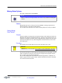
C6. Mining Modes
...............Mining, 2 Beam Mining, CAR Catalyst
Check Standards
Sample Presentation
in situ testing
Bagged or prepared sample testing
Optional Accessories
Typical Test Procedure
Mining Mode Options
Factors
Procedure
61
C7. Soil Modes
Soil and 3 Beam Soil
with Environmental and Exploration calibrations
Soil Mode Beam Selection
SmartShot
PowerShot
Check Standards
Sample Preparation
65
65
65
65
65
65
66
66
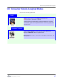
C8. Consumer Goods Analysis Modes
......... ..RoHS and Consumer Products
Introduction to RoHS Mode
Test Overview
Check Standards
Sample Presentation
IEC Quantitative Screening Requirements
Elemental Range/Limits for RoHS
Compliance
Grade Definitions for Screening
Introduction to Consumer Products Mode
67
A1. Overview: X-Ray Fluorescence (XRF)
.......Spectrometry
Basic Theory
History
Timeline for XRF Spectrometry
Elemental Analysis
EDXRF Spectrometers
73
4
62
62
62
62
62
62
63
63
63
68
68
69
69
69
70
71
72
73
75
75
76
77
80
83
85
87
88
89
90
91
101
102
104
108
Delta ™Family Handheld XRF Analyzers
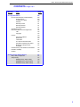
CONTENTS - Page 3 of 3
SECTION.........TOPIC....................................................PAGE
A7. Legal Information
Innov-X Delta Analyzer Limited Warranty
General Terms
Limitation of Liability
Software
Warranty Period
Warranty Returns
Warranty Repairs
Contacting Innov-X
End User Software License Agreement
Title
Copyright
License
Use of the Software
Restrictions
Termination
U.S. Government End Users
European Community End Users
Medical or Therapeutic Use
Prohibited
Limited warranty and Limitation of Remedies
Limitation of liability
General
109
109
109
110
111
111
111
111
111
112
112
112
113
113
113
114
114
114
114
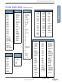
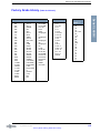
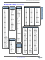
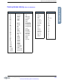
A8. Alloy Factory Grade Libraries
Alloy Library Complement
Tramp Library
Classic Factory Grade Library
Standard Factory Grade Library
Premium Factory Grade Library
117
117
117
118
120
122
115
116
116
5
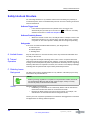
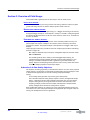
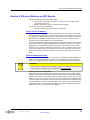
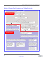
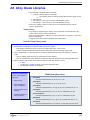
Delta Family End User Documentation Resources
Delta Family End User Documentation Resources
During Delta’s development and initial product shipments several End User documents have
been created. They are listed in the table below.
Delta Documentation Resources
6
Innovx
Release
Part #
Date
------------------------------Title-----------------------------------
103202_RevA
July/2010
Delta User Interface Guide (UI version 2.5))
103201_RevR
June/2010
Delta Family User Manual (This document)
103076_RevA
3/2010
Delta Family Quick Start
101593_RevA
11/2007
Window Replacement: Hinged Plate HandHeld Analyzers
102922_RevA
2/2010
Delta Family User Manual (Canadian Edition)
103158_RevA
3/2010
HOW TO: Setup and Configure A-020-D Teststand/Workstation
..................for Delta Analyzer
TBA
6/2010
HOW TO: Convert A-020-A or A-020-O Teststand/Workstation to
Support a Delta Analyzer
Chapter 4
Delta Family of Handheld XRF Instruments
Preface
This Preface provides the following information:
• “Manual Structure”
• “Document Conventions”
Manual Structure
This User Manual consists of eight chapters, ten appendices, this Preface, Table of Contents, and a Cover. Individual chapter material is summarized below:
C1. Introduction describes the basics of the system:
• The Innov-X Delta™ Family
• Visual tour of the instrument noting all the major components
C2. Safety Information describes general safety information:
• Priority Information
• General Precautions
• Electrical Precautions
• X-ray Safety
• Safety Interlock Structure
• Safe and Unsafe Usage Scenarios
• Radiation Doses for Several Scenarios
• Comparative Analysis of Typical Exposure
• Common Questions and Answers
• Delta Radiation Profile
• Required Certification
• Analyzer Shut-down Procedures
C3. Safety Administration describes safety program information:
• Radiation Safety Training Recommendations
• Dosimeter badges
• A typical dosimeter monitoring program
• Dosimeter service contractors
• Registration requirements
C4. Operations describes operations and testing procedures:
• Configure and Use Delta Docking Station (DDS)
• Start-up Procedure
• Cal Check Issues
• Battery Issues
• Conducting and Ending Test Operations
NOTE
Information concerning the Delta Family’s user interface is supplied in the companion
document “Delta User Interface Guide” (PN103202_Rev2.5 June/2010).
The goal is to provide revised Delta UI Guides when a substantial software change is
released.
C5. Alloy Analysis Modes describes five specific modes and calibrations including:
— Alloy
— Alloy Plus
— FastID
— Pass/Fail
— Precious Metal Additions
C6. Mining Analysis Modes describes three specific modes and calibrations including:
— Mining
— Two Beam Mining
PN 103201 Rev_A: June/2010
— Car Catalyst
7
Structure of This Guide
C7. Soil Analysis Modes describes two specific modes and two calibrations including:
— Soil
— Environmental
— Three Beam Soil
— Exploration
•
•
•
LEAP issues for Classic Delta (PiN detector)
Check Standards
Sample Preparation
C8. Consumer Goods Modes describes two specific modes including:
— RoHS
— Consumer Products
•
RoHS Mode provides a details from EU regulation directives which list the limits
for RoHS elements and information for qualitative measurements.
• Consumer Products Mode is dedicated to testing for Lead (Pb)
A1. Overview: X-Ray Fluorescence (XRF) Spectrometry presents background information and general knowledge, including:
• Basic Theory and X-ray History
• Elemental Analysis
• EDXRF Spectrometers
A2. Soil Testing presents information on using the analyzer for soil analysis within certain accepted guidelines, including:
•
•
•
•
•
•
•
Status for Field Portable XRF and Overview of Field Usage
Quality Assurance
Calibration for Innov-X Portable XRF
Effects of Moisture on XRF Results
Comparing XRF Results to Laboratory Results
Common Interferences
Sample Prep Procedures and Testing Protocols
A3. Specifications presents analyzer hardware and software specifications.
A4. Typical Delta Test Sequence
• Prerequisites noted by Mode
• Grade Libraries
• Check Standards
• Sample Presentations
• Typical Test Sequence
A5. User Maintenance provides a key procedure/technique:
•
•
•
Using the AC Power Adapter kit to replace a Li-ion battery
Using the stand-alone battery charger
Replacing a Prolene, Mylar, or Kapton Window
A6. Packing and Shipping gives the procedure for returning a unit to Innov-x.
• Warning Label for shipping products with Li-ion batteries
A7. Legal Information presents material, including:
•
•
•
•
•
Analyzer Limited Warranty including:
Limitation of Liability
Warranty Period, Returns, and Repairs
Instructions for Contacting Innov-X
End User Software License Agreement including:
• Use, Restrictions, and Termination of Software
• Liability Limitations
A8. Alloy Grade Libraries including the Alloy Factory Grade library for each Model, and
a “Tramp” Library with seven base alloys.
8
— Preface —
PN 103201 Rev_A: June/2010
Delta Family of Handheld XRF Instruments
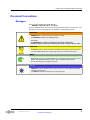
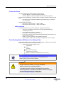
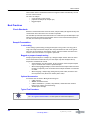
Document Conventions
Messages
There are four messages used in this Manual:
WARNING, CAUTION, NOTE, and GOTO.
They are characterized by an icon and a message box topped with a colored banner. The
message text is on a gray background. An example of each message is below:
T
WARNING
DEMANDS that you observe the actions given in the text.
The WARNING message has a bold type style.
Remember:
The WARNING icon signifies information that denotes a potentially
hazardous situation, which if not avoided, may result in serious injury or death.
CAUTION
SUGGESTS that you review the referenced details and heed the instructions offered.
The CAUTION message has a regular type style with emphasized keywords.
NOTE
REQUESTS that you pay particular attention to a specified procedure or piece of information. Adds details that make it easier to use the system and this manual.
The NOTE message has a regular type style.
GO TO
DIRECTS the user to another portion of this manual, or to other reference materials
containing relevant data.
The GOTO (or Pointer) message has a regular type style.
PN 103201 Rev_A: June/2010
— Document Conventions —
9
Structure of This Guide
Type Styles
These conventions are used to present information:
Convention
(Type Style)
Description
Bold
Indicates an action taken on a button or other item.
Italic
Menu commands, names of keys, buttons, tabs, or items from picklists.
User-entered text.
It is used for references to other documents, C(hapter) titles, and A(ppendix) titles
(for example, “… see “C2. Safety Information”).
Labels on unit’s I/O panels; panel or window names of the Ul (User Interface).
Courier typeface
Computer displayed text or filename.
Pagination
Page numbering in this Manual is consecutive with the Front Cover being assigned Page
Number 1. This enables the PDF document file and any hard-copy print to map to the
Page field information in the Adobe Reader.
10
— Preface —
PN 103201 Rev_A: June/2010
Chapter 4
Delta Family XRF Handheld Analyzers
C1. Introduction
C1 includes a:
• Description of the Innov-X Delta™ family of handheld XRF analyzers.
• Visual tour of the instrument(s) noting all the major features, and accessories.
Description of Delta System
What Is It?
The Delta is a handheld energy dispersive X-Ray fluorescence spectrometer, generally
referred to as an XRF analyzer.A complete Delta package consists of:
• Handheld analyzer using an integrated group of instrument components that are
sealed in an ergonomically designed, light-weight body. They include -• Controller
• Color touchscreen (ergonomically mounted interactive display)
• Membrane navigation keys
• Choice of detectors (PiN or SDD) to meet wide-ranging application
goals
Coordinated with these robust characteristics, the instrument’s key feature is Innov-X’s
proprietary control, data acquisition, and analysis software with customer configured
options.
Additional accessories (standard and optional) include:
• Li-Ion batteries (2) - {Standard}
• Delta Docking Station (DDS) Dedicated charging and calibration unit - {Standard}
• Rugged waterproof carry case - {Standard}
• Portable test stand to create a Delta workstation (A-020-D) {Optional}
• Soil foot (A-035) (Optional)
• Soil extension pole (990055) (Optional)
• Trimble Xplorer Package (Optional)
What Does It Do?
The expanded Delta family of handheld XRF instruments delivers fast and precise identification and analysis for elements from magnesium to uranium (Mg to U) depending on
the selected model. A weatherproof/dustproof ultra rugged design including an integral
heat sink permits users to conduct diverse analysis testing under severe operating conditions. An added convenience feature for field use is battery “Hot Swapping.”
Applications
The analyzer gives accurate chemical analysis for commercial or industrial areas, such as:
PN 103201 Rev_A: May/2010
• Positive Material Identification
• Scrap Processing
• Mining and Exploration
• Environmental Testing
• Consumer Safety
• Light Element & Aluminum Analysis
11
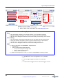
Delta Family: Types, Models, Modes and Calibrations
Delta Family: Types, Models, Modes and Calibrations
PREMIUM
STANDARD
CLASSIC
Delta Types and Models
Type
Modes
Models
Premium
Alloy
DP-2000
Environmental
DP-4000
Mining
DP-6000
RoHS
DP-6500
Alloy
DS-2000
Environmental
DS-4000
Mining
DS-6000
Standard
Classic
RoHS
DS-6500
Alloy
DC-2000
Environmental
DC-4000
Mining
DC-6000
RoHS
DC-6500
Modes and Calibrations
ALLOY Analysis
Alloy
MINING
Mining Mode
Alloy Plus
2 Beam Mining
FastID & Pass/Fail
Car Catalyst
Precious Metals
Environmental
GOODS
Lead in Paint (HUD)
Lead in Paint (Industrial)
THIN
CONSUMER
SOIL Analysis
LEAD PAINT
RoHS
Filter Analysis
Dust Wipe
Consumer Products
Exploration
12
PN 103201 Rev_A: May/2010
— Delta Family: Types, Models, Modes and Calibrations —
Delta Family XRF Handheld Analyzers
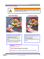
Inspection
Inspection
Use this procedure:
1. Remove the carry case from the shipping cartons; save cartons.
2. Open the carry case
Remove the shipping documentation
3. Verify that all the parts and accessories are included.
Remember that the case has TWO FOAM LAYERS.
4. Verify that no visible damage occurred during shipping.
WARNING
If there is damage to any of the components, DO NOT attempt
to use the instrument.
Immediately contact Innov-X Customer Support at:
•
United States: 1-781-938-5005
•
Europe: +31 (0)73 62 72 590
•
Canada: 1-778-960-6279
•
Australia: 02-9577-9500
Or call your local distributor.
GO TO
•
•
•
See C4. Operations, Page 45 & 50 Battery Issues for battery charging
information.
See “Delta User Interface Guide” (PN 103202) for a complete description
of the Innov-X application’s User Interface.
See A7. Legal Information for warranty, liability, and software licensing
information.
13
PN 103201 Rev_A: May/2010
— Inspection —
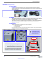
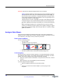
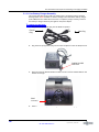
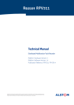
Tour of the Delta Package
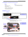
Tour of the Delta Package
The figure below depicts Delta’s major components as initially shipped to a customer.
Note that the protective foam in the Carry Case has TWO LAYERS.
2
o
Foam: Top Layer
1
o
Cutout
Component Key
—Foam: Top Layer—
1
Delta Analyzer
2
Carry Case
3
Docking Station Charger
4
USB Cable #1
5
USB Cable #2
6
Li-ion Batteries (2)
7
Cal Check Coupon
8
Extra Windows (Bag of 10)
9
End/User Documentation
—Foam: 2nd Layer—
10
Docking Station
11
AC Power Adapter (Optional)
7
o
3
o
o
10
o
6
4
o
5
o
9
o
8
o
11
o
Foam: 2nd Layer
14
PN 103201 Rev_A: May/2010
— Tour of the Delta Package —
Delta Family XRF Handheld Analyzers
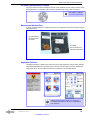
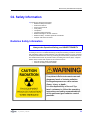
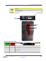
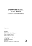
Tour of Instrument
1. Handheld Analyzer
Component Key
10
o
Delta - All Models
1
Delta Analyzer
2
Probe
3
Measurement Window
4
Hinged Window Plate
5
Docking Station Connector
6
Trigger
7
Handle - Non-Slip Rubber Grip
8
Battery Boot
9
Data Port w/ Rubber Cover
10
Heat Sink
11
I/O (Power) Switch w/ LED Indicator
12
X-ray Warning Light Array
13
Touchscreen for User Interface
14
Navigation Buttons
3
o
(Premium Model Shown)
1
o
(Prolene Film)
10 •
o
2
o
4
o
•
•
5
o
o
12
6
o
7
o
• o
11
8
o
13
o
10 Hea
o
t Sink
9
o
• o
14
o
14
•
•
Navigation Buttons
•
• •
12
o
11
o
11 I/O Power Switch w/LED Indicator
o
12
o
X-ray Warning Light Array
15
PN 103201 Rev_A: May/2010
— Tour of Instrument —
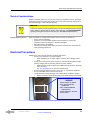
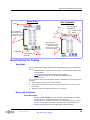
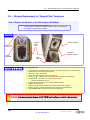
2. Delta Docking Station (DDS)
2. Delta Docking Station (DDS)
Component Key
1
o
Delta - All Model
o
4
2
o
o
3
1
Delta Docking Station (Empty)
2
Analyzer Signal/Control Connector
3
Spare Battery Charge Socket
4
CalCheck Test Cup (316 stainless steel coupon)
5
Docking Station (Loaded)
6
Second Battery in Socket
7
Data Port(s): — Docking Station ->Rear
— Analyzer -> Left Side
8
Input Power (12 VDC)
9
Indicator Lights
a
Second Battery Charging
b
Analyzer Engaged
5
o
6
o
7
o
See C4/Pages 44-45
for more information
7
o
7
o
8
o
9
o
8
o
9
o
3
o
9
o
7
o
8
o
b
o
.
16
PN 103201 Rev_A: May/2010
— 2. Delta Docking Station (DDS) —
a
o
Delta Family XRF Handheld Analyzers
3. Accessories- List the Standard and Optional Accessories
Standard
Optional
• Batteries
• AC Power Adapter (Battery Replacement)
• Delta Docking Station (DDS)
• A-020-D TestStand/Workstation for Delta
• DDS Power Adapter
• USB Cables 1 - USB mini to USB A
• USB Cable 2 - two part powered data cable
• Windows- Bags of Kapton and Prolene films
• Cal Check (Standardization) Coupon
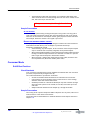
STANDARD Accessories
Batteries
Two removable Li-ion batteries are standard accessories for the Delta.
See Chapter 4, Page 50
“Battery Issues”
Push the white Push button
and the LEDs indicate thepercentage of charge.
Delta Docking Station (DDS)
This is key accessory. It provides three functions:
• Cal Check by one of two means - “On Demand” or Automatically
• Charge internal battery in handle
• Charge additional battery in auxiliary socket
See Chapter 4, Page 46
“Use DDS for Start Up &
Initial Cal Check”
Spare Battery Socket
Calibration Standard
Control Socket
(Pins)
Data Comm
with USB
•
DC Power Input
•
“Cradle”
Power Indicators
PN 103201 Rev_A: May/2010
— 3. Accessories- List the Standard and Optional Accessories —
17
STANDARD Accessories
Power Adapter for DDS
See Chapter 4, Page 44
“Configure DDS”
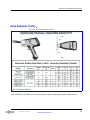
I/O Cables
PN 101310: This standard accessory provides a means to transfer information into or out of the sealed
analyzer. It is good practice to export the current day’s testing results to your PC.
PN 101310
USB Data Cable
Mini USB B Connector
USB A Connector
PN 103209 and 103210: This is a two part assembly that supports communication
between the Delta Docking Station and a PC.
.
Part One
PN 103209
USB Repeater Cable
USB A Female Connector
USB A Male Connector
Data Cable Assembly
Part Two
PN 103210
USB Adaptor
Male to Male
USB A Connector
USB B Connector
18
PN 103201 Rev_A: May/2010
— STANDARD Accessories —
Delta Family XRF Handheld Analyzers
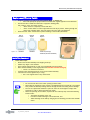
Cal Check (Standardization) Coupon
This part is used as a reference sample to provide a test standard for a Cal Check procedure if the
Docking Stations is not available. The instrument indicates when a Cal_Check is necessary.
See Chapter 4, Page 51
“Cal Check Information”
Measurement Window Films
A bag of 10 window films are a standard accessory. The composition of the film is model and application dependent
PN 103115 REV A
Kapton Windows
for Classic
PN 102999
Prolene windows for
Standard and Premium
Application Software
The Delta instrument is shipped with proprietary InnovX data acquisition and processing software
and Windows Embedded CE® operating system. The User Interface employs an icon-based home
page graphic style. Factory calibration has been completed on all purchased modes.
Sedately User Interface Guide” (PN 103202) for
a complete description of the Innov-X application’s
User Interface.
19
PN 103201 Rev_A: May/2010
— STANDARD Accessories —
OPTIONAL Accessories
OPTIONAL Accessories
AC Power Adapter
PN 100043: This accessory enables the user to operate the instrument without the limitation
of battery charge status. The unit comes with approximately ten feet of power cord that defines the
effective range of use.
PC Software
This application package permits an operator to execute Innovx S/W functions from a PC. With cable
PN 101310, a user can connect from the Delta’s mini-USB data port to a PC’s USB port.
This package is optional for a handheld instrument and standard for A-020-D TestStand/Workstation.
When used with the A-020-D the proper configuration cable is the powered USB assembly
(PN 103209 - PN 103210)
XRF Workstation
The Delta XRF Workstation is comprised of two major components:
• A-020-D Test Stand, and
• Any Delta analyzer
In this configuration, the Delta is controlled by Innovx Delta PC Software. The open-beam handheld
instrument is converted to a closed-beam workstation.
See PN 103158 document:
“HowTo-Setup & Configure
Delta XRF Workstation” for
complete instructions.
Hinged Lid
Test Chamber
Tour of XRF Workstation
The XRF Workstation offers the following features:
• Portable, light-weight, shielded enclosure
• A rugged and repeatable testing environment
• Easily erected in laboratory or at remote field site
In this configuration the Delta (an open-beam handheld
instrument) is converted to a safe closed-beam system
20
Hinged Legs with Locks
PN 103201 Rev_A: May/2010
— OPTIONAL Accessories —
Chapter 4
Delta Family Handheld XRF Analyzers
C2. Safety Information
C2 presents the following information:
• Radiation Safety Information
• General Precautions
• Electrical Precautions
• X-Ray Safety
• Compliance
• Instrument Usage Scenarios
• Radiation Dosage for Several Scenarios
• Radiation Safety: Common Questions and Answers
• Analyzer Shut Down Procedure
Radiation Safety Information
Always make Operational Safety your HIGHEST PRIORITY.
The Delta Handheld XRF Analyzer is a secure and dependable instrument when used
according to Innov-X’s recommended testing techniques and safety procedures. However,
this instrument produces ionizing radiation; only individuals trained in correct operating
techniques and authorized to use X-ray producing devices should be permitted to use it.
The radiation detected at any outside surface (excluding the Prolene, Mylar, or Kapton
window area) is below that required for an unrestricted area.
• Heed all warning labels and messages
• Observe the safety interlock features
.
X-ray tubes in Delta instruments can emit
dangerous levels of ionizing radiation.
Prolonged exposure can cause serious
illness, injury, or death.
It is the responsibility of Innov-X Systems’ customers to follow the operating
instructions and safety recommendations
of this guide and good radiation control
practices.
PN_103201 Rev_ A: May/2010
21
Radiation Safety Program
Radiation Safety Program
Innov-X strongly recommends that organizations using Delta analyzers implement a formal Radiation Safety Program that includes:
• Dose monitoring of critical personnel.
• Monitoring of area radiation levels.
• Information specific to the site and application of the XRF system.
• An annual review (and update, if necessary).
“C3. Safety Administration” provides a more comprehensive safety discussion for operators and managers.
X-Ray Safety
X-ray safety is a priority at any time and in any testing situation.
WARNING
•
Innov-X analyzers must be used by trained and authorized operators,
according to proper safety procedures. Improper usage may circumvent
safety protections and could potentially cause harm to the user.
•
Heed all warning labels and messages.
•
DO NOT USE the instrument if there is any chance that it is damaged or
might leak radiation. In such a case, arrange for qualified personnel to
perform a radiation safety test and repair any analyzer damage.
General Precautions
Apply these general safety guidelines when managing or operating the Delta instrument:
• Retain and follow all product safety and operating instructions.
• Comply with all warnings on the product and in the operating instructions.
Comply with the precautions listed in this section to reduce the risk to:
•
Users
—
—
—
•
Physical injury
Electric shock
Radiation exposure
Equipment damage
—
—
Measurement window
Overheated electronics and other internal components
22
— C2. Safety Information —
PN_103201 Rev_ A: May/2010
Delta Family Handheld XRF Analyzers
Service Considerations
Except as expressly noted here, do not service any Innov-X product yourself. Opening or
removing the external housings may expose you to electric shock and the instrument to
mechanical damage. It also voids the warranty.
CAUTION
If service is required, it must be performed by Innov-X or its authorized service representatives. Failure to observe this can result in loss of warranty. The ONLY EXCEPTION is
replacing a damaged measurement window (see “A5. Window Replacement”).
Damage Requiring Service
Types of problems or conditions that require service are (but not limited to):
• Power cords are damaged.
• Excessive or corrosive liquids spilled on the instrument or accessories.
• Instrument impacted, dropped, or physically damaged.
• Noticeable signs of overheating.
• Instrument or docking station does not perform normally when you follow the
usual operating instructions.
Electrical Precautions
Guidelines for safe electrical operation of a Delta instrument:
• Use the correct battery or AC power adapter.
• Install the battery or AC power adapter carefully, don’t damage connections.
• Use the correct external AC power sources for the Delta Docking Station (DDS)
(battery charging and Cal Checking) and the AC power adapter:
• Ensure that the voltage is appropriate (100V-240 V/ 50-60 Hz) for operating
either accessory.
See “A3. Specifications” for electrical specifications.
• Do not overload an electrical outlet, power strip, or convenience receptacle.
• Do not exceed 80% of the branch circuit rating.
• Comply with the warning messages on the under side of the Battery Charger.
• Similar precautions should be observed for the Delta Docking Station (DDS).
WARNING
— DO NOT EXPOSE TO WATER
— FULLY ENGAGE BATTERY
CONNECTOR
— ONLY USE RECOMMENDED
POWER SUPPLY
— DO NOT OBSTRUCT AIRFLOW
— DO NOT OPEN
PN_103201 Rev_ A: May/2010
— Service Considerations —
23
Electrical Precautions
Cables and Cords
The Delta instrument and docking station is delivered with:
• AC power adapter (1) for Docking Station (standard)
• AC power adapter (2) as battery replacement for instrument (optional)
Each device has a standard IEC 3 conductor power cord which includes a safety grounding
plug.
• If necessary, have an authorized individual replace these plugs to conform to
local conventions.
Two data cables are supplied:
• Data cable (1) with connectors — USB A to USB B
• Data cable (2) with connectors — USB A to mini USB B
Cable Guidelines
Use these guidelines to ensure safety and proper equipment performance:
• The power cords MUST be connected to a properly grounded and easily
accessible power outlet.
• Use a surge protector device, if possible.
• Do not defeat or bypass the ground conductor.
• Do not pull on cords or cables. Grasp the plug housing when removing the cord
from the electrical outlet.
• Install all cords in accordance with applicable regulations.
• If you substitute a USB cable, ensure that the length doesn’t exceed 10 feet.
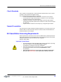
Delta Docking Station (DDS) and Li ion Battery Packs
Plug the Delta Docking Station (and optional battery charger, if utilized) into a grounded
electrical outlet that is easily accessible at all times.
• To handle battery packs properly do not:
—
—
—
—
—
—
Disassemble
Crush
Puncture
Short external contacts
Dispose of in fire or water
Expose to temperatures higher than 60 oC (140 oF).
GO TO
See “C4. Battery Issues” for instructions concerning Batteries, the
Battery Charger, and the AC Power Adapter.
—
WARNING
Danger of explosion if battery is incorrectly substituted.
Replace only with Innov-X specified batteries.
Used batteries may be returned to Innov-X Systems for disposal.
If returning batteries, or equipment with batteries installed, the shipping
container must display a special caution label.
See “A6. Packing and Shipping” for label details.
24
— C2. Safety Information —
PN_103201 Rev_ A: May/2010
Delta Family Handheld XRF Analyzers
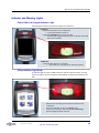
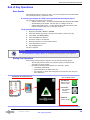
Indicator and Warning Lights
Power Switch w/ Integral Indicator Light
The Delta power switch is located at the upper rear of the unit.
POWER ON
• Press the I/O switch to turn on the power.
— A green LED indicator comes on.
• This switch DOES NOT turn on the x-ray tube.
— No tube power supplied until the Innov-X software is launched
and a test is initiated.
POWER OFF
• Press and hold switch for >3 seconds.
— Unit powers off. (See page 36 for more Exit options)
X-Ray Indicator Light Array
An indicator light array (six red LEDs) alerts the operator when the tube is receiving
power, and when x-rays are emitted from the analyzer through the measurement window.
•
•
•
•
PN_103201 Rev_ A: May/2010
When the unit is initially powered ON, the Indicator array
remains Off.
As test is conducted, array is in a flashing state.
At the test’s conclusion, the array stays on continuously
until the beginning of the next test.
— Indicator and Warning Lights —
25
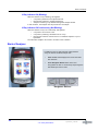
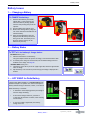
Back of Analyzer
X-Ray Indicator ON (Blinking)
When the indicator array is flashing, this signifies:
• X-ray tube is powered to full operational level
• Internal filter wheel is in operational position
• Analyzer is emitting x-ray radiation through the analysis window.
In this condition, the analyzer must be pointed at a test sample.
X-Ray Indicator ON Continuously (Not Blinking)
When the indicator array is on continuously, this signifies:
• X-ray tube’s current is set to 0.0
• X-ray tube is producing a minimum level of x-rays
• Internal filter wheel is closed so there is no radiation exposure to you or
bystanders.
The instrument is safe to be carried or set down in this condition.
Back of Analyzer
In addition to the I/O switch and the X-Ray indicator
array, the back of the Delta analyzer has:
•
Touch screen which displays and controls the Delta
User Interface.
•
Three Navigation Buttons below the screen.
They permit the user to conveniently step through the
Test Results Spectrum screens.
Navigation Buttons
26
— C2. Safety Information —
PN_103201 Rev_ A: May/2010
Delta Family Handheld XRF Analyzers
X-Ray Label
The Delta has a warning label affixed to the lower surface of the probe.
The analyzer has a label on the lower surface
of analyzer’s probe/nose.
• This label is required by most
regulatory agencies. Do not remove it.
•
The label term “WHEN ENERGIZED”
refers to the condition where the tube is
fully energized and the filter wheel is
open.
•
This condition corresponds with the
blinking red LEDs that comprise the
X-ray indicator array.
Other Safety Features
Proximity Sensor
The Delta automatically detects when it is engaged with a test sample.
It immediately shuts off the X-ray tube if:
(a) Initially there is no sample in front of the window,
XXX— or —
(b) Instrument is pulled away from the sample before the test time has expired.
PN_103201 Rev_ A: May/2010
— Back of Analyzer —
27
Safety Interlock Structure
Safety Interlock Structure
For controlling the Delta’s X-ray emissions and therefore minimizing the possibility of
accidental exposure, there is a standard safety interlock structure consisting of the three
features listed below.
Software Trigger Lock
•
If five minutes elapse between tests (default time), the trigger locks
automatically and you must tap on the lock icon
to unlock it. See Safety
Software instructions in “Delta User Interface Guide”.
Software Proximity Sensor
•
Within two seconds of a test start, the analyzer detects a sample in front of the
measurement window. If not, the test aborts, the filter wheel closes, and the
x-rays shut off. The tube is placed in standby and the red light stops blinking.
Safeguards
As an owner of an Delta handheld XRF instrument, your safeguards are:
A. Limited Access
B. Trained Operators
C. Shielding Issues
A. Limited Access
Keep the instrument in a controlled location, where only trained and authorized users
are likely to have access.
B. Trained
Operators
Keep a sign with the analyzer indicating that in order to use it an operator must have
completed a training class provided by your company, or must have attended an Innov-X
training course and completed any other requirements as dictated by the local regulating
authority. When the Innov-X system is turned on, the controller screen displays a message
indicating that the system should only be used by authorized personnel.
C. Shielding Issues
Background
The Delta emits a tightly collimated beam of X-ray radiation. The beam projects many
meters when only air attenuates it.
NOTE
Refer to governing regulations on compliance in the jurisdiction installed, dose limits,
etc. Requirements differ from state to state, region to region, country to country.
DO NOT rely solely on this manual for instruction.
Action
Adequate shielding is achieved by:
• Establishing a no-admittance zone sufficiently distant from the instrument’s
measurement window that allows air to attenuate the beam.
• Enclosing the beam working area with protective panels (for example, 1/8”
stainless steel can attenuate the beam to background levels)
Contact your Innov-X Systems representative for assistance and suggestions on interlocks
and applications for limiting radiation exposure.
28
— C2. Safety Information —
PN_103201 Rev_ A: May/2010
Delta Family Handheld XRF Analyzers
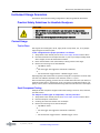
Instrument Usage Scenarios
The Delta is used in several testing configurations. Obey the guidelines listed below.
Practical Safety Guidelines for Handheld Analyzers
T
WARNING
• DO NOT POINT the unit at yourself or any other person during operation.
• Never perform a test by holding the sample with your fingers or in the palm of
your hand.
• Always wear both a ring-style and a badge-style dosimeter.
Correct Usage
Test in Place
Test targets can include pipes, valves, large pieces of scrap metal, soil, or any sample
large enough to be tested in place.
In this configuration the proper procedure is as follows:
1.
2.
Always observe the relevant parts of the Practical Safety Guidelines shown above.
Point the instrument at the sample such that no part of your body (including hands
and/or fingers) is near the measurement window.
3. Ensure that the Delta’s nose (with window) is firmly placed on the target.
4. Perform the test using one of these methods:
• Tap Start on the UI
— or —
• Pull the trigger (this toggles the instrument to ON state)
— or —
• Pull-and-hold the trigger with the “deadman trigger” active.
Employing Steps 3 & 4 assures that no operator’s body part is exposed to an excess radiation dose. The radiation detected at user interface areas is < 5 μSv/h.
Take care that during testing, personnel are not located within three feet (one meter) of
the Delta’s probe head, in the direction of the x-ray beam. Provided the window is completely covered, there is minimal radiation being emitted around the area of the sample.
Small Component Testing
Examples of small component targets include metal turnings, weld rod, wires, fasteners,
nuts and/or bolts.
For analysis of these types of components, use this procedure:
1.
2.
3.
4.
PN_103201 Rev_ A: May/2010
Always observe the relevant parts of the Practical Safety Guidelines shown above.
Place the sample on a flat surface.
Carefully place the nose/window over the sample.
Perform the test using one of these techniques:
• Tap Start on the UI
— or —
• Pull the trigger (this toggles the instrument to ON state)
— or —
• Pull-and-hold the trigger with the “deadman trigger” active.
— Instrument Usage Scenarios —
29
Correct Usage
1. Sample lying on a flat surface
SAFETY PRECAUTIONS
WARNING
Do not test samples while sitting at a desk or table
If the desk is made of wood or another non-metallic
material, some radiation will penetrate the desk and
may provide exposure to legs or feet.
ANALYTICAL PRECAUTIONS
NOTE
If the sample does not completely cover the window,
ensure that your background surface does not contain
metals or even trace levels of metals, as this may affect
the accuracy of the XRF result. The XRF may report the
presence of additional metals in the surface material.
2. Clamp-held sample
NOTE
A handheld plastic locking clamp can be an
effective and safe tool when analyzing small,
irregular shaped samples.
30
— C2. Safety Information —
PN_103201 Rev_ A: May/2010
Delta Family Handheld XRF Analyzers
Incorrect (Unsafe) Usage
T
WARNING
Never hold a sample in your hand such that any part of your body or appendages
are exposed to the x-ray beam. Testing samples in this way may generate significant radiation exposure to your fingers.
Unsafe Testing Technique
The sample is held up to the measurement
window with fingers. The sample does not
completely cover the window.
Even though the analyst is wearing a ring
dosimeter, this is an unsafe testing technique.
Here, the only value that the ring provides is
to validate the level of unnecessary radiation
exposure that has been experienced.
Unsafe Testing Technique
The sample is held up to the measurement window with fingers. The sample does not completely cover the window.
To compound the danger, the analyst is not
wearing a ring dosimeter.
There is no measure of the radiation exposure
endured.
Summary
InnovX repeats the Warning ---
NEVER hold a sample in your hand.
Testing samples in this way generates significant radiation exposure to your fingers.
PN_103201 Rev_ A: May/2010
— Incorrect (Unsafe) Usage —
31
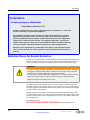
Compliance
Compliance
Complying Agency Statements
United States of America: FCC
Changes or modifications not expressly approved by Innov-X Systems, Inc. could void
the user’s authority to operate the equipment.
This equipment has been tested and found to comply with the limits for a Class A
digital device, pursuant to Part 15 of the FCC Rules. These limits are designed to
provide reasonable protection against harmful interference when the equipment is
operated in a commercial environment. This equipment generates, uses and can
radiate radio frequency energy and, if not installed and used in accordance with the
instruction manual, may cause harmful interference to radio communications.
Operation of this equipment in a residential area is likely to cause harmful interference in which case the user will be required to correct the interference at his own
expense.
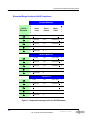
Radiation Doses for Several Scenarios
In this section we provide data, concrete examples of use and misuse of the analyzer and
common questions and answers we encounter when training personnel on the safe use of
the Innov-X analyzer. The goal is to explain scenarios of safe versus improper usage.
WARNING
For the x-ray energy emitted by portable XRF analyzers (8-60 keV region), the bone in
the fingers will absorb radiation about 3-5 times more than soft tissue, so the bone
would be at an elevated radiation risk compared to soft tissue.
For this reason, no person shall hold a test specimen in front of the window with the
fingers in the direct beam, or direct the beam at any part of the human body.
Reference: Health Physics 66(4):463-471;1994.
The table below presents radiation doses for normal operating conditions and also for
examples of misuse of the analyzer and even extreme misuse. Innov-X provides installation training that includes detailed radiation safety training and documentation designed
to prevent misuse of the analyzer.
Although the doses shown below are derived from experiments with TLD (thermo-luminescent dosimeters) and may or may not represent actual absorbed dose in human tissue
and bone in each scenario, they are examples of the level of x-ray radiation being emitted from the device.
The message is simple:
USE CAUTION AND PROPER TECHNIQUE when operating the device.
32
— C2. Safety Information —
PN_103201 Rev_ A: May/2010
Delta Family Handheld XRF Analyzers
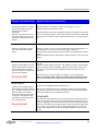
Example: Instrument Usage
Radiation Exposure and Comments
Normal Operation- Dose to Hand
User analyzes samples according to
standard operating procedures
described in this manual.
Assumption:
Operator using system with x-ray
tube ON for eight hours/day, five
days/week, 50 weeks/year. (Alloy
sample).
Maximum exposure is to operator’s hand, at the trigger is < 1μSv/h.
Annual exposure to hand is then < 2mSv.
Maximum exposure under ICRP regulations is 500 mSv for radiation workers and
50 mSv for the general public. Thus continuous operation provides a dosage 250
times lower for a radiation worker and and 25 times lower for the general public.
Normal Operation- Dose to Torso
Analyzer is used under the same
operating conditions described
above.
Exposure to Torso is so low it cannot be measured (essentially background). To
be conservative we use 1/2 the value as the trigger, < 0.5μSv/h.
Annual exposure using operating conditions above is then estimated at less than
1 mSv.
Maximum allowed is 20 mSv under ICRP for radiation workers (1 mSv for general
public).
Misuse Example 1:
At the window, in the primary beam, the maximum dose to the fingers is 20,000
mSv/hr.
Assume an operator performs a 10 sec. test (typical). The dose to the operator’s
fingers or hand is 20,000 x (10/3600) = 550 mSv. If the operator did this just
once a year he would exceed the allowable annual dose of 500 mSv to an
extremity.
Operator holds samples in front of
window with fingers, such that fingers are directly in the primary
beam. Presumption is sample does
not block any radiation.
Take the extra time to test a sample on a surface or use a testing stand.
Note: If the operator takes a shortcut and places his/her fingers within the
primary x-ray beam at the window, they will exceed the annual dose rate.
Do not do this!
Misuse Example 2:
Operator places analyzer against
body and pulls the trigger to start a
test. Analyzer tests to preset testing time (usually ten seconds)
unless operator pulls trigger again
to stop test. This applies to analyzer being in contact with operator or with bystander.
Do not do this!
PN_103201 Rev_ A: May/2010
Dose at exit of sampling window is 20,000 mSv/h.
Dose for a ten second exposure with analyzer in contact with Torso: 550 mSv.
If an operator did this act just once, he would exceed the annual safe dosage to
the torso of 20 mSv/year by a significant amount!
PLEASE NOTE:
The maximum dose of 20 mSv/year is a whole body limit, which does not truly
apply in this case because the x-ray beam size is small (about 25 mm2 area at
the port). Applying correction factors for the beam size is complex and beyond
the scope of this manual. The important point is that for proper operation there
is no reason to ever expose any part of the human body directly to the x-ray
source. This example serves to provide estimated exposure in the event this
occurs.
— Radiation Doses for Several Scenarios —
33
Radiation Doses for Several Scenarios
Misuse Example 3:
Operator manages to initiate a test
for ten seconds running normal soil
mode and exposes a bystander that
is standing ten cm away from analyzer port.
What is exposure to bystander?
Note: The proximity sensor would
automatically shut down the x-ray
tube immediately, so this is an
extremely improbable occurrence.
It would require a malfunction of
the instrument - this safety feature
in NOT modifiable.
Dose to bystander at ten cm is 215 mSv/hr. For a ten second exposure the dose
is 0.6 mSv. This is 33 times lower than the allowable dose to a nuclear worker in
a year. This would have to happen 33 times to for that worker or bystander to
obtain the maximum allowable dose.
Formula for calculating other scenarios:
DOSE (in mSv) = 6T/D
2
D = distance from port in inches
T = testing time
Example: Bystander is 30 cm away from port for a 30 second test. In this case
the dose is calculated as:
DOSE = 6(30)/302 = 0.2 mSv
Note 2: Equations to scale these to
other scenarios involving longer or
shorter tests, and bystander being
at distances other than ten cm are
provided at right.
Comparative Analysis:
Radiation Doses from Typical Exposures to Ionizing Radiation
Activity
Typical Dose
Smoking
2.8 mSv per year
Dental x-ray
100 μSv per x-ray
Chest x-ray
80 μSv per x-ray
Drinking water
50 μSv per year
Cross country round-trip by air
50 μSv per trip
Mammogram
1-2 mSv per examination
Yearly exposure from background*
radiation
* depends on geographic location
3.6 mSv
34
— C2. Safety Information —
PN_103201 Rev_ A: May/2010
Delta Family Handheld XRF Analyzers
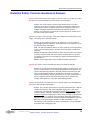
Radiation Safety: Common Questions & Answers
Question: When I’m shooting a piece of pipe or valve on a rack or on a table top, is there
any exposure to people standing several feet away from the analyzer?
Answer: Even a thin amount of a dense metal sample (three to four mm
thickness, not Al alloy) is enough to completely attenuate the emitted x-ray
beam. Shooting a piece of material that covers the sampling window on the
analyzer completely shields any bystanders from radiation exposure.
However, use good practice: Keep the area clear of people for at least four to
five feet in front of the analyzer.
Question: If I forget to lock the trigger, I pick up the analyzer and accidentally pull the
trigger, is that dangerous to nearby personnel?
Answer: No, this example of misuse is not dangerous, but it may produce a
non-negligible radiation exposure to nearby personnel. For an exposure to occur,
the following things must happen.
First, you must be holding the analyzer so that a bystander is actually standing
in the x-ray beam being emitted. Just being near the analyzer is totally safe
otherwise.
Second, the bystander must be within one meter from the nose of the analyzer
to receive any appreciable dose. If all of these conditions are true, the dose
received by a bystander is still extremely low. Please see Misuse Example 3 in
the table above.
Third, it would require failure of the proximity hardware and software.
Question: Do I need to create restricted areas where I am using the analyzer?
Answer: No, provided you are following normal operating procedures there is no
reason to restrict access to an area where the analyzer is in use. However, the
operator should take precautions to keep any personnel more than three feet
away from the sampling window of the analyzer in the event of accidental
misuse as detailed above. Should operators also elect to test small samples as
shown on pages 34 and 35, they should also be sure that no personnel are
standing within about four to five feet of the sampling window.
Question: How does the x-ray tube in the Innov-X system compare to a radiography system used for taking images of metal parts?
Answer: The x-ray tube used in the Innov-X system produces between 1,000 and
10,000 times less power than most radiography systems (0.5-1 watt versus
multiple-kW). A portable XRF is designed to perform surface analysis of alloys
and other samples, whereas a radiography system is designed to shoot x-rays
entirely through metal components in order to obtain an image on the other side
of the test object. For example, many tube-based radiography systems use a
300-400 kV tube and currents in the tens or hundreds of milliamperes (mA). The
Delta uses a tube operating at a maximum of 40kV and typically 6 -10 μA.
The radiation levels produced by an Delta are thousands, or tens of thousands,
times lower than a radiography unit.
PN_103201 Rev_ A: May/2010
— Radiation Safety: Common Questions & Answers —
35
Analyzer Shut Down
Question: Should we use dosimeter badges with the Innov-X analyzer?
Answer: Dosimeter badges are required by some provincial regulatory agencies,
and optional with others. Innov-X recommends that operators wear badges, at
least for the first year of operation, as a general precaution to flag any misuse
of the analyzer. Dosimeter badges are available for the torso (generally worn in
a shirt pocket) and also as “ring” badges.
The best practice is to wear a ring badge on a finger on the opposite hand used
to hold the analyzer. This records accidental exposure for the most likely case –
an operator grabbing a small sample and holding it in one hand while analyzing
it.
Note: These badges generally have a threshold of 100 μSv and are renewed
monthly. So it takes several cases of misuse even to obtain a reading on a typical
badge. When purchasing a badge, obtain the type used for x-ray and low energy
gamma ray radiation.
Analyzer Shut Down
There are several techniques for shutting off the Delta. They can be categorized by
whether the action is taken under normal or emergency conditions. Shut down or turned
off is defined as: The analyzer cannot provide X-ray emissions.
Under normal conditions
Use one of following actions:
• Press the trigger.
• Tap STOP icon on the UI touchscreen.
• Navigate from Setup > Exit, then choose the Power OFF icon.
•
•
Release the trigger if in “Deadman Trigger” mode.
Press the I/O power switch; ensure that the On/Off LED goes off.
In an emergency
Because the Innov-X system is a battery-operated, x-ray tube-based analyzer, the Emergency Response plan is simple. If you believe that the analyzer is locked up in an OPEN
position, the red X-ray indicator array remains illuminated or blinking:
1. Press the I/O power switch as noted above. If the power does not turn off, continue
to Step 2.
2. Open the battery cover and immediately remove the battery.
If you are using the AC Power Adapter:
• Remove the Battery Eliminator from the Delta’s handle
— or —
• Pull the AC cord from the AC Power Adapter or pull the plug from the
receptacle.
36
— C2. Safety Information —
PN_103201 Rev_ A: May/2010
Delta Family Handheld XRF Analyzers
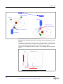
Delta Radiation Profile
This is the current Delta Radiation Profile.
TEST CONDITION: Instrument run at normal setting for mode and represents typical production unit.
PN_103201 Rev_ A: May/2010
— Delta Radiation Profile —
37
NOTES
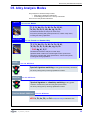
38
PN_103201 Rev_ A: May/2010
Chapter 4
Delta Family Handheld XRF Analyzers
C3. Safety Administration
C3 provides information regarding:
• Radiation safety training recommendations
• Dosimeter badges
• A typical dosimeter monitoring program
• Dosimeter service contractors
• Typical registration requirements for operating XRF equipment (in the USA)
Radiation Safety Training Recommendations
Individual companies and states have specific regulations and guidelines for using ionizing radiation generated by an X-ray tube.
NOTES
For the convenience of clients, Innov-X has compiled a list of recommendations that:
• Provide generic guidance for an ALARA (as low as reasonably achievable)
approach to radiation safety.
• Do not replace the requirement to understand and comply with specific policies
of any state or organization.
Personal Monitoring
Radiation control regulations may require implementation of a radiation monitoring program, where each instrument operator wears a film badge or TLD detector for an initial
period of one year to establish a baseline exposure record. Continuing radiation monitoring after this period is recommended, but may be discontinued if accepted by radiation
control regulators. See Dosimeter Suppliers for a list of film badges providers.
Proper Usage
Never point the instrument at a person. Never point the instrument into the air and perform a test. Never hold a sample in your hand during a test.
Establish Controlled Areas
Restrict access to the location of instrument storage and use to limit potential exposure
to ionizing radiation. In use, the target should not be hand held and the area at least
three paces beyond the target should be unoccupied.
Specific Controls
When not in use, store the instrument in a locked case or locked cabinet.
When in use, keep it in the direct control of a factory trained, certified operator.
Time - Distance - Shielding Policies
Operators should minimize the time around the energized instrument, maximize the distance from the instrument window, and shoot into high density materials whenever possible.
Prevent Exposure to Ionizing Radiation
All reasonable measures, including labeling, operator training and certification, and the
concepts of time, distance, & shielding, should be implemented to limit radiation exposure to as low as reasonably achievable (ALARA).
PN_103201 Rev_ A: May/2010
39
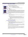
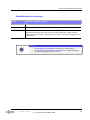
Dosimeter Badges
Dosimeter Badges
A dosimeter badge consists of a radiation-sensitive material, generally an aluminum
oxide crystalline layer, which is worn in a small container. It is most often attached to a
person's clothing, on a belt loop, or shirt pocket. It is worn on the body in location(s) that
most closely simulate the pattern of potentially absorbed dose.
The protection can also be provided in a plastic ring format. Here the detection material
is lithium fluoride crystal.
Dosimeter
Clip-on Style
Dosimeter
Ring Style
These devices record a person’s accumulated radiation exposure over a period of time.
They monitor individuals working with, or near someone working with devices which emit
ionizing radiation.
Dosimeter badges are required by some regulatory agencies, and are optional
with others.
Innov-X recommends that (at a minimum) all Delta operators wear badges (both clip-on
and ring styles) for the first year that their system is in use.
NOTE
• When purchasing a badge or ring, always select the type used for X-ray and low
energy gamma radiation.
• Innov-X suggests that the ring badge be worn on a finger of the opposite hand used
to hold the analyzer. This records accidental exposure for the most likely case: An
operator grabbing a small sample and holding it in a hand while analyzing it.
Every country (including every region, state, or province within a country) can have differing regulations. Always consult your local radiation protection authority or Innov-X
Systems for information and recommendations.
40
— C3. Safety Administration —
PN_103201 Rev_ A: May/2010
Delta Family Handheld XRF Analyzers
Dosimeter Safety Program
A typical dosimeter-based safety program uses the following steps:
1. The company develops a dosimeter program with an independent service contractor.
• They establish the quantity of badges needed and the
frequency of analysis (a monthly or quarterly interval)
2. The company receives the first lot of badges and provides them to their
analyst/operators.
3. At the end of the interval:
• The company collects the badges and returns them to the service contractor for
analysis.
• Simultaneously, the service contractor delivers another lot.
4. The company provides the new set of badges to maintain a continuous
protection /monitoring program for their employees.
5. The service contractor prepares a report for the company that tabulates any X-ray
dose received and identifies any personnel with readings higher than typical
background radiation.
6. The safety monitoring cycle repeats with Steps 1 through 5.
.
NOTE
The service contractor’s written records are very important to a company’s overall safety
documentation plan.
Dosimeter Suppliers
Some dosimeter service companies are:
Company
Location
Telephone
AEIL
Houston, TX
713-790-9719
Global Dosimetry Solutions
Irvine, CA
800-251-3331
Landauer
Glenwood, Il
708-755-7000
• Landauer, Inc.
Oxford, England
+44-1 86-537-3008
• Nagase Landauer, ltd.
Japan
+81-3-36 66-4300
• LCIE Landauer
Paris, France
+33-(0)1-40 95 62 90
• Landauer
Beijing, China
+86-10-62 21 56 35
PN_103201 Rev_ A: May/2010
— Dosimeter Badges —
41
Registration Requirements
Registration Requirements
Contact Innov-X for assistance with locating registration requirements information.
• Most states require some form of registration. Generally they require the
registration to be received within 30 days of receipt of the system.
• Some states require no registration.
• Some states require notification in advance.
Customers are advised to consult their local radiation protection authority for specific
regulatory information.
Typical Device Registration Information
The following information is usually requested by a licensing agency:
Purpose of device:
Response is Analytical or Industrial.
Be sure to inform the government registration office that the system will NOT be
used for radiography or for medical uses.
Radiation Safety Officer:
List person who monitors training, safe use, and controls access to the system.
Authorized Users:
List the analyst/operators who have been trained and authorized by the instrument
owner and/or regulating agency to operate the XRF equipment.
Operating parameters of the Delta XRF analyzer:
8— 40 kV, 5 - 200 uA max.
Type of system:
Response is: Handheld/Portable
User Training Specified:
Indicate that only individuals receiving manufacturer training, documented by a
manufacturer’s training certificate, will operate the system. Additional training
may be required. Verify with the local regulating agencies the level and type of
training required.
Personal Monitoring
Many government agency registration forms require that you indicate whether or not
you intend to perform dosimeter monitoring.
See “Dosimeter Safety Program” on previous page for information
regarding typical personal radiation monitoring.
CAUTION
Always keep the following documentation at the job site:
• Copy of License Registration
• Other pertinent government agency documentation
• Copies of any dosimeter analysis reports
• Copy of this equipment’s User Manual.
42
— C3. Safety Administration —
PN_103201 Rev_ A: May/2010
Delta Family Handheld XRF Analyzers
C4. Operations
This chapter provides information regarding:
• Configure the Delta Docking Station (DDS)
• Use DDS for Initial Cal Check
• Operation - General
• Start Up Procedure
• Snapshot of Delta User Interface
• Typical Test Procedure
• Ending Test Operations
• Battery Issues
• Additional Cal Check Information
• TIPS - Things You Should Know About the Delta
Safety First !
As emphasized in “C2.Safety Information,” it is a priority to keep the analyzer operator’s
safety in mind at all times.
• Operators, before turning on the analyzer or using the Delta Docking
Station, should review the safety procedures (“C2.Safety Information”).
Set Up and Use the Delta Docking Station
Background
The Delta Docking Station (DDS) provides several key functions:
• Supports an automatic or on-demand Cal_Check procedure
• Charges the “Main” battery located in the instrument’s handle
• Simultaneously charges a “Spare” battery in an auxiliary socket
• Provides control information so that both batterys’ status can be monitored
• Allows data communication from the Delta to a PC via a powered USB cable
The first phase for preparing to operate a Delta involves:
1. Configuring the DDS with its power and communication cables
2. Using the DDS to support the Delta’s initial:
a.
b.
Start up sequence, and
Cal Check procedure.
NOTE
A new instrument is shipped with two fully charged Li Ion batteries.
Therefore, prior to initially using the analyzer, it is not necessary to charge
a battery.
GO TO
•
•
PN_103201 Rev_ A: May/2010
See Pages 45 and 50 for battery information, including charging, changing,
determining status, and Hot Swap techniques.
See Page 51 for Cal Check background information.
43
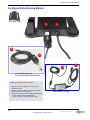
Configure Delta Docking Station
Configure Delta Docking Station
Rear View - DDS
3
o
2
o
4
o
3
o
2
o
PN 103209 & PN 103210
Powered Hub USB Cable Assembly
Configure DDS with this procedure:
1.
2.
3.
Plug the AC power adapter’s line cord (1) into
suitable AC outlet.
Plug the AC power adapter’s DC jack (2) into the
12 Vdc socket on the rear of DDS
{Option at this point: Powered USB cable assembly}
— Insert connector B (3) into DATA port
— Insert connector A (4) into USB port of PC
44
— Configure Delta Docking Station —
Power Adapter for DDS
PN_103201 Rev_ A: May/2010
1
o
Delta Family Handheld XRF Analyzers
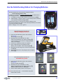
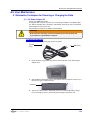
Use the Delta Docking Station for Charging Batteries
The Delta analyzer has a multi-purpose standard accessory:
the Delta Docking Station or DDS.
In addition to providing an automatic Calibration Check, the DDS delivers
two charging functions:
1. It charges the installed “Main” battery in the instrument’s handle.
2. Simultaneously, it charges a spare or “Dock” battery when its inserted
into the special auxiliary charging socket.
Charge status is shown in real-time on the Delta’s display screen.
The second docked battery’s status is also shown by the battery icon located
on the rear left side of the DDS.
(either “charging = red” or “full = green”)
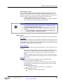
Battery Status Screen
(Delta inserted in DDS)
Delta Docking Station Procedure for
Battery Charging Functions:
1. Ensure that the DDS has DC power cable installed
See page 44
The Icon lights are Off {1}
2. With Delta Off, place instrument in cradle.
Take care that Analyzer Icon comes On (Green) {2}
The main battery in the handle is charging although
there is no indicator.
3. If Delta On, the Battery Status Screen appears
4. Place a spare battery in the auxiliary socket
Battery Icon is On (Red - unless fully charged) {3}
5. Both batteries will charge; their real-time charge status
is displayed.
6. When both batteries are fully charged, the Icons display
Green. {4}
Cradle
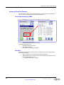
Delta Docking Station Procedure for
Automatic Cal_Check
{2}
{1}
1. Ensure that the DDS has DC power cable installed
See page 44
The all Icon lights are Off {1}
2. With Delta On, place instrument in cradle.
Take care that Analyzer Icon comes On (Green) {2}
Battery Status screen is displayed.
3.
Ensure that the Battery Status screen stays On.
NOTE: Do not exit this screen -->> the automatic Cal_Check
function will not work.
PN_103201 Rev_ A: May/2010
— —
{3}
{4}
45
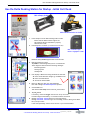
Use the Delta Docking Station for Startup - Initial Cal Check
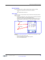
Use the Delta Docking Station for Startup - Initial Cal Check
DDS w/Empty Cradle
DDS w/Premium Delta in Cradle
1.
2.
Place analyzer into the Delta Docking Station cradle.
Ensure that the Delta indicator light is ON.
This signifies that the instrument is properly
seated in the cradle.
Press analyzer’s I/O switch (>1 second to turn it ON.)
Tools
Icon
DDS - Indicator Light
Delta is engaged in cradle
Radiation Safety NOTICE appears after a few seconds.
3.
Read and respond to notice
Tap START to acknowledge that you are a certified user.
The UI begins its launch with the following messages:
Initializing System
Starting System
Loading Files
4.
Unit displays a Test screen using the Mode last selected.
4a. If the mode should be changed, go to Home screen.
4b. Select the Mode button
4c. Choose the desired Mode
5.
Return to Test {now with your selected Mode)
Note that message Cal Check Required is present.
6.
Choose Tools icon:
This launches Test Setup screen with Cal_Check button
7.
Tap Cal_Check
If necessary, unlock the Trigger with the icon at top of screen.
Procedure begins immediately; it concludes in about 15 seconds.
Message Cal Check - Passed means you may begin testing.
Message Cal Check - Failed will give error message, such as”! Wrong Count Rate”
Re-try the procedure
If unit fails repeatedly, contact InnovX service or your local distributor.
8.
46
PN_103201 Rev_ A: May/2010
— Use the Delta Docking Station for Startup - Initial Cal Check —
Delta Family Handheld XRF Analyzers
SNAPSHOT of Delta’s User Interface
The Delta’s user interface is introduced by the startup Radiation Safety and Initialization screens.
Main operations then revolve around the Home screen.
Test
Conditions
Mode Setup
Mode
Tools
Results
Summary
Test
Setup
Results
PN_103201 Rev_ A: May/2010
— SNAPSHOT of Delta’s User Interface —
47
Typical Test Procedure
Typical Test Procedure
Background
Details of routine testing operations vary depending on the selected analysis mode.
Some relevant modes for Delta XRF users are:
• Alloy Modes
—Alloy Plus
—Fast ID & Pass/Fail
—Precious Metals
• Mining Modes
—Two-Beam Mining
—Mining
—Car Catalyst
• Soil Modes
—Environmental
—Exploration
• Consumer Goods
—RoHS
—Consumer Products
For the test sequence (below) the instrument has:
• Mode selected (Soil 3 Beam), and
• Cal Check procedure successfully completed.
To conduct a typical test:
1.
Remove the instrument from the Delta Docking Station. Place the the measurement
window flush against the sampling area. Ensure the sampling area is covered by the
window.
T
WARNING
Do not point the unit at yourself or any other person during operation. Do not test
small samples in your hand. Place them on a surface for testing.
See C2, Safety Information, Pages 29-31 for examples of safe and unsafe testing
techniques.
2.
Use one of these techniques to initiate the X-ray beam:
a. Tap Start Test (Green Arrow Icon), or
b. Pull the trigger (toggles unit ON); can release the trigger during the test, or
c. Pull-and-hold the trigger (deadman trigger function is enabled)
This is a mandatory technique in Canada.
Trigger options are configurable from:
Setup > Trigger Hardware > Trigger Settings
The Test screens are as follow:
Test results with progress
status bar
Test result complete;
Elements are listed
48
— Typical Test Procedure —
Spectrum screen for this
result (ID: 4/29/10 #22)
PN_103201 Rev_ A: May/2010
Delta Family Handheld XRF Analyzers
End of Day Operations
Save Results
When finishing testing for the day (or shift, or current session} InnovX recommends that
test results be saved (e.g. exported) to a PC.
A necessary prerequisite is a DATA connection between the analyzer and PC.
This connection is made in one of two ways:
• Analyzer in DDS cradle — use the powered hub USB cable assembly (PN 103209
and PN 103210) from the DDS’ rear Data port to a USB port of the PC
• Analyzer NOT in DDS cradle — use the mini USB B to USB A (PN 101310) cable
from the analyzer’s Data port to a USB port on the PC
The UI operational sequence is:
1. Navigate from Home > Results > Calendar
2. Select Year, Month, Day listing; it lists the total number of tests for the day
3. Select Tools, then Results Setup
4. Select the Export icon (button)
5. Choose the results to be exported
6. Name the export file (or accept default name)
7. Select Destination to save to
8. Tap the Export button
The file is exported.
GO TO
•
See “Delta SW User Interface Guide” for the details (including options) of this sequence.
Ending Test Operations
When testing and exporting are complete, the user has the following options:
• Turn off Delta with I/O switch or UI (see Exit Options procedure below);
store unit in a secure location
• Place Delta in Docking Station and use the “Automatic” option:
• Leave Delta powered ON;
• Ensure that DDS is On (Delta ICON is lit);
• Unit initiates Cal_Check after being idle for five minutes, then every ten
hours thereafter.
Exit Option Procedure from UI
User has three options:
Soft Reboot
Restart OS and
restart IX app.
Power OFF
Turn analyzer
off after
confirmation.
Exit Icon
Setup Screen
Relaunch
Restart IX app.
PN_103201 Rev_ A: May/2010
— End of Day Operations —
49
Battery Issues
Battery Issues
1 — Changing a Battery
To CHANGE the battery:
1. Hold the instrument by the handle,
upside down, so the bottom of the
instrument base is pointing upward
with the nose pointing away from the
operator.
2. Pull the rubber latch and lift cover.
3. Remove the existing battery using the
tab. A new instrument will not have an
installed battery.
4. Insert the charged battery into the
analyzer with the battery connectors
facing to the left. The battery slot is
keyed so that the battery can be
inserted only one way.
1
o
2
o
3
o
2 — Battery Status
To TEST a Li-ion battery’s charge status:
EXTERNAL battery test —
1. Push the white button on the battery.
The green lamps indicate the percent of charge, from less than 25% to 100%.
2. If a battery has a charge of less than 25%, use the Delta Docking Station to
establish a full charge. See Page 45.
INTERNAL MAIN battery test —
1. The battery icon from any UI screen (upper right side) shows an approximate
value of charge.
2. Tap the battery icon and a more precise charge percentage is displayed as a
number.
3 — HOT SWAP for Delta Battery
A battery HOT SWAP capability is a standard feature with
the Delta analyzer. An operator can remove and replace a
battery without having to shut down, restart, or Cal Check.
When the battery is removed:
• A “Shutdown” status display gives the percentage of
internal charge remaining.
•
If the internal charge reaches 0, you have to
re-start the unit with the I/O switch, after inserting
a fresh battery.
•
If red X-ray indicator lights flash, the battery
voltage is too low.
50
— Battery Issues —
PN_103201 Rev_ A: May/2010
Delta Family Handheld XRF Analyzers
Cal_Check Information
Cal_Check Facts
Question: What is involved with the Cal_Check procedure?
Answer: The analyzer:
•
Collects a spectrum on a known standard (Alloy 316 Stainless Steel)
•
Compares a variety of parameters to values stored when the instrument
was calibrated at the factory.
•
When comparisons are within pre-set tolerances, the unit determines
that it remains properly calibrated.
GENERAL FACTS INCLUDE:
•
•
•
•
•
Cal_Check
Procedures
Cal_Check must be performed when the analyzer requests the procedure.
The Start button and trigger are disabled until a successful Cal_Check is
achieved.
You can run a Cal_Check at any time during InnovX software operation, except
during a test.
When Cal_Check is in progress, the x-ray indicator light assembly blinks.This
indicates that the X-ray tube is energized and the filter wheel is operational.
In addition, a status bar appears on the UI display, showing the percentage
completion for the measurement.
The Cal_Check procedure takes about 15 seconds.
There are two separate techniques:
• In the test laboratory - Use the DDS to initiate “on-demand” procedure.
Described above in “Use the DDS for Startup - Initial Cal Check”:
Also have the “Automatic” option, as follows:
Leave Delta powered On and InnovX software running;
Ensure that DDS is On (Delta ICON is lit);
Unit initiates Cal_Check after being idle for five minutes,
then every 10 hours thereafter.
•
1.
2.
3.
4.
In the field - Use the Coupon {the procedure is described below)
Place the 316 stainless steel Cal_Check coupon on a flat surface.
See C2. Safety Information, Page 29 for safety measures that must be observed.
Position the analyzer’s measurement window flush over the coupon.
With the Test Setup screen invoked, tap the Cal Check icon. There are now two
techniques to choose from:
• Tap the “Start Test” icon, or
• Pull the trigger (or pull-and-hold if using “Deadman Trigger”)
The procedure takes about fifteen seconds.
NOTE
Improperly positioning the window over the coupon can result in a failure.
5.
6.
When Cal_Check completes successfully, you may begin testing.
If Cal_Check fails, ensure that:
• Coupon is positioned correctly.
• X-ray indicator assembly is blinking during the procedure.
• You have waited several seconds before starting the procedure.
7. If Cal_Check fails again,
• Shut down the Delta software.
• Shutdown and restart the analyzer.
• Launch another attempt to Cal Check.
If Cal_Check fails repeatedly, contact Innov-X Systems Customer Service or your local distributor. Contact information is available at appendix A6. Packing and Shipping
PN_103201 Rev_ A: May/2010
— Cal_Check Information —
51
TIPS - or - things you should know about the Delta
TIPS - or - things you should know about the Delta
System Information
To call information “About InnovX” tap the X (InnovX icon) in upper left
of UI screen. This provides various firmware and software versions that
are installed on the analyzer.
UI Screen Note
All User Interface screens have a time-out (power saving) feature that
causes the screen to go blank after 45 seconds if the UI is not
accessed or the unit is not moved.
However, the analyzer is still running.
Restore the screen by tapping it or by moving the instrument.
Battery Status Info #1
When you turn on the instrument and you may not be aware that the
battery is low, the X-ray indicator (Red LEDs) flashes dimly and briefly.
The unit will not turn ON. Swap out the battery.
Battery Status Info #2
The on-screen battery icon (in upper right corner of UI) shows
“real-time” battery charge status in a graphical way.
Tap this icon to receive a numeric value for battery charge level.
Delta Docking Station to Delta Analyzer: Contact Status
Keep the rubber boot attached to instrument when inserting it into
the DDS. This helps ensure that the DDS contact pins are engaged.
The DDS analyzer icon (rear left corner) should be ON.
If the rubber boot is not available, and the analyzer icon remains OFF,
use a small piece of padding under the handle to ensure contact.
52
— TIPS - or - things you should know about the Delta —
PN_103201 Rev_ A: May/2010
Delta Family Handheld XRF Analyzers
C5. Alloy Analysis Modes
Alloy analysis for the Delta family includes:
• Wide range of modes and calibrations
• Outstanding performance for a variety of materials
There are five Alloy modes/calibrations:
ALLOY
Use with: ALL Models
Ti, V, Cr, Mn, Fe, Co, Ni, Cu, Zn, W, Hf,
Ta, Re, Pb, Bi, Zr, Nb, Mo, Ag, Sn, Sb
Fundamental Parameters Analysis for metal alloys.
Alloy library including 300+ grade specifications, common tramp limits,
including full editing capabilities.
ALLOY
ALLOY Plus
Use with: Premier and Standard Only
Ti, V, Cr, Mn, Fe, Co, Ni, Cu, Zn, W, Hf,
Ta, Re, Pb, Bi, Zr, Nb, Mo, Ag, Sn, Sb
PLUS Mg, Al, Si, P
Fundamental Parameters Analysis for metal alloys.
Optimized beam condition for extended light element performance.
Alloy library including 300+ grade specifications, common tramp limits,
including full editing capabilities.
ALLOY PLUS
FastID
Use with: All Models
Spectral signature matching for alloy grade & chemistry calculation.
Full library editing & alloy matching capabilities included.
Pass/Fail
Use with: All Models
Spectral signature or chemistry matching for alloy grades.
Customer created library with min/max grade specifications.
Full library editing & alloy matching capabilities included.
Precious Metals Additions Use with: All Models
ADDS Ir, Pt, Au, Rh,
PN_103201 Rev_ A: May/2010
and
Pd to Analytical Analysis calibration suite.
53
Introduction to Alloy Analysis Modes
Introduction to Alloy Analysis Modes
ALLOY
ALLOY PLUS
The Delta family of instruments currently presents six unique modes for alloy analysis.
The core analytical analyzer modes/types are:
Alloy mode - Classic (PiN detector based) type
Alloy Plus mode - Standard (SDD detector based) type
- Premium (SDD detector based) type
All three analyzer types can support additional alloy-oriented modes, such as
FastID
Pass/Fail
Precious Metals (No added details)
Alloy analysis utilizes a Fundamental Parameters (FP) algorithm to determine elemental
chemistry. This method calculates chemistry from the spectral data, without the requirement of stored fingerprints. The Analytical FP calibration is done at the factory, and
requires no user set-up or recalibration. The software also searches an alloy grade library
to produce a grade match based on the calculated chemistry. Analytical mode can provide a grade ID and chemistry in as little as one second, with increased precision for
longer test times.
Alloy mode/Classic type supports Ti, V, Cr, Mn, Fe, Co, Ni, Cu, Zn, W, Hf, Ta, Re, Pb,
Bi, Zr, Nb, Mo, Ag, Sn, Sb.
Alloy Plus mode /Standard type and Premium type supports light elements Mg, Al,
Si, and P in addition to the core list of elements from the Alloy mode.
Standard and Premium units expand the Limits of Detection range permitting
operators to analyze these light elements without a vacuum or helium purge
requirement.
Both modes have a feature, Altitude Compensation, which automatically corrects calibrations based on barometric pressure.
Determination of Grade Identification:
Analytical modes utilize a Factory Grade Library consisting of a set of minimum and maximum values for each element in an alloy.
There is a SPECIFIC Alloy Factory Grade Library for EACH Delta model.
See appendix A8. Alloy Grade Libraries for a listing of the alloys that are contained in
each Factory Grade Library.
Additionally, every analyzer is shipped with a “Tramp” library comprised of seven base
alloys. These seven items with their min/max element values are increasingly valuable to
fast and accurate sorting in Pass/Fail and FastID modes.
The libraries can be searched individually or together. All libraries, including each Factory Grade Library, can be edited by the user. However, InnovX strongly suggests that
users NOT edit the Factory Grade Library. Instead, copy the Factory Grade Library to a
USER library, then make any edits on it.
54
— C5. Alloy Analysis Modes —
PN_103201 Rev_ A: May/2010
Delta Family Handheld XRF Analyzers
Match Number Concept
After calculating chemistry with the Fundamental Parameters algorithm, Innov-X compares the chemical composition values to grade tables stored in a grade library. The
application calculates the value for a parameter called Match Number. This provides an
indication of how close the measured alloy’s chemistry is to library values.
• The lower the Match Number, the better the match.
• A Match Number of 0 is an exact match, meaning that the calculated chemistry
for all elements falls within the grade table specifications.
GO TO
•
•
See “Delta User Interface Guide” (PN 103202) for a complete description
of the Innov-X application’s User Interface.
See A8. Alloy Grade Libraries for listing of each model’s “Factory Grade
Library”
• A “Spectral Fingerprint” library that would be used for “FastID” and
“Pass/Fail” analysis is created by the customer.
Match Issues
There are three Match determination possibilities provided within the Analytical modes:
EXACT MATCH
An unknown alloy is matched to one of the grades contained in the Grade Libraries, and a
Grade ID appears on the Results screen. Often other grades are listed with their accompanying Match Numbers. The analyst has the opportunity to view their elemental chemistries and see how they differ from an exact match.
MULTIPLE MATCHES
In some cases, several grades are shown as possible matches. This can signify one of two
conditions:
• There was not enough statistical information to definitively separate two or
more alloys. The actual identification of the unknown alloy is one of the grades
listed. Often increasing the testing time makes it possible to separate the
alloys.
• There was sufficient statistical information, but the test sample did not meet
any of the existing specifications with enough precision to cause an exact match
identification.
NO MATCH
If no matches are found within the libraries, the words NO MATCH appear.
There are several causes for a NO MATCH result:
• The test sample does not meet any of the specifications in the Grade Library.
• The test sample is coated; Remove the coating by grinding, filing, or sanding
and repeat the test.
• The testing time was too short.
—
•
—
PN_103201 Rev_ A: May/2010
Increase the testing time and measure the sample again.
The Match Number is too low.
If possible, increase the Match Number
— C5. Alloy Analysis Modes —
55
Introduction to Alloy Analysis Modes
Scrap and Recycling Features
Delta analyzers in Alloy or Alloy Plus modes support many new features to specifically
enhance scrap processing by maximizing speed and accuracy.
Grade Match Messaging (GMM)
User or Yard Manager can assign pop-up messages to specific alloy grades
•
Grade
•
•
•
Quick start for next test, or
view the chemistry details with one click
Match Messaging offers:
Immediate sorting instructions
Less operator training
More efficiency and higher throughput
SmartSort
Automated sorting decisions that allow users to maximize speed and sorting accuracy.
Some features include:
• Specific grades set up to automatically extend testing time.
• Maximize efficiency for speed testing by automatically extending test time for
light elements (Mg, Al, Si, P, S)
• Eliminate unnecessary long tests
56
— C5. Alloy Analysis Modes —
PN_103201 Rev_ A: May/2010
Delta Family Handheld XRF Analyzers
Nominal Chemistry
Nominal Chemistry looks for ‘invisible’ elements, based on grade ID, including:
• Elements not tested under active beam, (like Al in Beam 1)
— or —
•
XRF invisible elements (like B or C)
Tramp Library
Analyzers with Alloy or Alloy Plus mode come pre-loaded with a tramp library based on
industry standards.
• Operators may assign other “Tramp” elements with max tolerated concentration
for individual elements in seven unique graded families.
• Analyzers can report tramp material (optionally) and simplify grade match by
not counting small, expected amounts of tramp elements against the grade
match.
Nominal Value
Tramp Element
See appendix A8. Alloy Grade Libraries for a discussion of the Tramp Library concept,
including:
• How the InnovX Tramp Library works
• Practical advantages of the Tramp element approach
• List of seven Tramp Base Alloys
PN_103201 Rev_ A: May/2010
— C5. Alloy Analysis Modes —
57
Introduction to Alloy Analysis Modes
Test Sample Considerations
Coated or Painted Samples
XRF is a surface analysis technique, where X-rays penetrate a very short distance into
most alloy samples. Therefore, the analyzer detects what is on the surface of an alloy,
rather than what comprises the bulk of the material. If a material has been coated,
plated, painted, or has had some sort of surface treatment, such as heat treating, it may
be misidentified.
For example, a steel piece painted grey may show high concentrations of titanium
from the paint, and may be misidentified as a titanium alloy. In another example,
large amounts of metal dust or turnings on a surface may be detected by the
analyzer.
To ensure proper identification of coated materials, grind an area slightly larger than
the analyzing window to remove the coating. It is important to select the correct
grinding material so as to not interfere with the analysis.
Do not use Silica for a Silicon analysis.
It may not be necessary to completely clean and polish all materials, however, remove
obvious metal dust.
Mixed Samples, Heterogeneous Materials
Often finished metal pieces may consist of more than one type of metal. In addition, you
may wish to measure mixed turnings, or an assortment of small pieces. In these cases,
remember that the analyzer measures the entire area covered by the analyzing window
and reports an average chemistry. For turnings, this is useful, as the analyzer provides an
average composition. However, if two or more pieces of metal cover the window, the
results is just an average reading, and may tell very little about the composition of one
piece or the other.
When shooting metal pieces, or welds, ensure that only the metal of interest is
covering the analyzing window.
Small and Irregularly Shaped Samples
To measure samples smaller than the analyzing window:
• Increase the testing time.
— and —
• Maximize the material in contact with the window.
The precision of analysis for small parts measurements is reduced, as the signal from
smaller samples is less than for samples that completely cover the window. If possible,
analyze the largest, flattest side of an irregularly shaped object.
GO TO
•
•
See A4. Typical Test Procedure for description of a Test sequence.
See “Delta User Interface Guide” (PN 103202) for a complete description
of the Innov-X application’s User Interface.
58
— C5. Alloy Analysis Modes —
PN_103201 Rev_ A: May/2010
Delta Family Handheld XRF Analyzers
Introduction to FastID Mode (All Models)
FastID mode is designed to quickly identify an alloy. It uses an empirical calibration
method known as a “type” calibration. It is most useful where the number of alloys to
test is small and well known.
FastID is best suited for Positive Material Identification (PMI) and QA/QC applications.
For example, where alloy producers or fabricators handle materials that may
be very similar or where maximum user simplicity is a primary concern.
This mode offers:
• Simplified results (grade name only or less information on tramp elements).
• A narrow, customized grade library base upon stored spectral fingerprint
reference standards.
• Full chemical analysis based on reference standard assays.
• Results which are the best combination of SPEED and ACCURACY.
— A Grade and Chemistry result in as little as one to two seconds.
• User selectable match criteria settings.
• Expansion of up to 500 additional alloy grades and assays (alloy chemistries) —
password protected.
• Multiple independent grade libraries. You choose to search one or more
libraries.
• All libraries are editable
How FastID works:
Prerequisite: The operator creates a “custom FastID fingerprint’ library by testing an
array of reference standards. This list spans the number of alloys for which he is interested.
1.
2.
3.
4.
Delta’s XRF process allows a test sample to create a spectral fingerprint.
Analyzer compares this spectral fingerprint to entries from library of many certified
spectra, the “custom FastID fingerprint” library.
Analyzer finds the best spectral match to the sample spectra: thus identifying and
reporting the matching alloy grade.
If concentration data has been entered for the standards, the instrument then
calculates the sample’s chemistry.
The reported chemistry data are an extrapolation from standard intensity data
stored in the customer -generated fingerprint library.
The user gets a real time grade match and a precise report of the chemical
composition of the sample.
NOTE
— Because FastID mode performs a spectral match to a library of reference standards,
it is important that before testing, a “likely” stored reference standard be in the
customer-created FastID fingerprint library.
PN_103201 Rev_ A: May/2010
— C5. Alloy Analysis Modes —
59
Introduction to Pass/Fail Mode (All Models)
Introduction to Pass/Fail Mode (All Models)
Pass/Fail mode is designed for high-throughput alloy sorting and quality control.
Mode Features
•
•
•
All test samples are sorted by comparison to an operator-selected reference
standard.
Results are displayed as a PASS or a FAIL, depending on whether they match the
reference standard.
Pass/Fail criteria may be based on:
• “quality of fit” to the selected spectral fingerprint
— or —
•
•
• elemental chemistry.
Pass/Fail ranges may be implemented for one or more elements.
This mode offers a full range of options from the simple sorting of mixed loads in
a recycling facility to QC on specific element(s) of the most complex
superalloys.
Pass/Fail mode has two options: Fingerprint and Chemistry:
1. Fingerprint Option
Select this method when the goal is to determine whether or not test samples are
a specific grade.
Fingerprint Pass/Fail and FastID use the same method to determine a match.
Data from analyzed samples are compared to the reference standard fingerprint.
If the differences between the fingerprints are small enough, the sample is judged to
be of the same grade as the reference sample.
This method requires:
Only that the library contains a valid fingerprint for the reference standard.
2. Chemistry Option
Select this method to determine whether the chemistries for specific elements fall
within specified min/max grade specifications.
Chemistry pass/fail process is:
1.
Analyzer uses the fingerprint method to determine whether the sample matches the
reference sample.
If it does not, it automatically fails.
2. If Step 1 has a match, the alloy chemistry is calculated from assays stored for the
standard fingerprint.
3. The calculated chemistry for each element is compared to the values stored in a
Grade Table.
In order for a sample to pass, all the chemistries must be within “n” standard
deviations of the min and max values specified in the grade table.
Number “n” is specified by the user.
This method requires three items:
(1) a valid fingerprint, (2) assays for that fingerprint, and (3) Min/Max values saved
in the library.
60
— C5. Alloy Analysis Modes —
PN_103201 Rev_ A: May/2010
Chapter 4
Delta Family Handheld XRF Analyzers
C6. Mining Modes
There are three Mining modes
MINING
Use with: ALL models
Ti, V, Cr, Mn, Fe, Co, Ni, Cu, Zn, W, As, Pb,
Bi, Zr, Mo, Ag, Cd, Sn, Sb
ALL
(elements may be customized on request)
Fundamental Parameter based calibration for ore grading and percent-level
analysis of
process bulk samples.
Suitable for measurement of percentage level analyte concentrations, 0.5% and
greater.
2 BEAM MINING
Use with: Premier and Standard Only
Mg, Al, Si, P, S, Cl, K, Ca,
Ti, V, Cr, Mn, Fe, Co, Ni, Cu, Zn, W, As, Pb,
Bi, Zr, Mo, Ag, Cd, Sn, Sb
(elements may be customized on request)
Mining mode optimized for SDD based systems to enhance SPEED and
LOD for light elements
CAR Catalyst
Use with: All Models
Ti, V, Cr, Mn, Fe, Co, Ni, Cu, Zn, W, Hf,
Ta, Re, Pb, Bi, Zr, Nb, Mo, Ag, Sn, Sb
PLUS Rh, Pt, Pd
Accurate analysis of bulk recycled catalyst materials
Mode ICON
T.B.A.
The Mining modes/types are:
Mining mode - Classic (PiN detector based) type
2 Beam Mining mode - Standard (SDD detector based) type
Beam Mining mode - Premium (SDD detector based) type
Car Catalyst mode - All types
PN_103201 Rev_ A: June/2010
61
Best Practices
These modes utilize a Fundamental Parameters algorithm which automatically corrects
for inter-element results.
The units can analyze:
• in situ (directly on the ground),
• prepared soil samples (in sample cups)
• bagged samples
Best Practices
Check Standards
Measure a check standard after each Cal Check, and periodically throughout the day. This
confirms that data continues to be as accurate as possible.
The standards provided with Delta instruments are contained in special XRF sample cups.
These cups have film windows (through which the soil can be viewed and analyzed) on
one side, and solid caps on the other side.
Sample Presentation
in situ testing
In situ testing is performed by pointing the analyzer at the ground. Clear any grass or
large rocks away and hold the analyzer with the probe head front flush to the ground.
Since dirt can accumulate on the analyzer window, wipe the window clean after each
analysis. Ensure the window is not ripped or punctured.
Bagged or prepared sample testing
Analyze prepared samples in a sample cup, through its Mylar window. Place the instrument’s measurement window directly over the sample cup with the Mylar side up.
Preparation considerations include:
• Avoid measuring very thin samples, as this can affect results. Prepare samples
cups to contain at least 15 mm of packed samples.
• When analyzing bagged samples, ensure that sufficient sample material exists in
the bag to completely cover the window with a sample thickness of a minimum
of 15 mm.
• When using bags, cheaper bags (having thinner plastic walls) are better than
more expensive ones (which have thicker plastic walls).
Optional Accessories
Accessories that can assist in Mining mode testing are:
• A-035: Soil Foot
• 990055: Soil Extension Pole
• A-020-D: Workstation - portable, fully shielded, closed beam test stand for
bench-top or remote controlled testing.
• Trimble Xplorer Package
Typical Test Procedure
GO TO
See “A4. Typical Test Procedure” for description of a Delta Test sequence..
62
— C6. Mining Modes —
PN_103201 Rev_ A: June/2010
Delta Family Handheld XRF Analyzers
Mining Mode Options
Test length in Mining Mode is user defined.
GO TO
Refer to “Delta User Interface Guide, User Factors” for procedure to modify User
Factors..
Factors
Mining modes allow you to create your own set of factors, focusing on particular elements of interest or correcting for matrix effects.
You can make several different Factor tables, allowing analysis of a variety of samples.
Setting Mining
User Factors
Example:
A group of samples covering the full concentration range for each element of interest are
identified. Each sample is homogenized and split. A portion of each sample is sent to an
outside lab for analysis. The other portion is analyzed with the analyzer. For best results
ensure that the samples are very well homogenized, and characterized, so the correlation is quite good.
Procedure:
Plot the data. Innov-X data must be on the X-axis, lab values on the y-axis.
CAUTION
ENSURE that you use this order: Innov-X data on X-axis and lab data on the Y-axis.
Determine the linear best fit with both the slope and intercept for each element.
The slope and intercepts for these graphs are entered directly into the analyzer. In many
cases it is sufficient to enter just a correction for the slope as the intercept is almost
zero. In others, enter the slope and intercept.
You can enter multiple sets of user factors for different applications, or different ore
bodies. A group of factors is given a name, and then the factors are entered. The factor
set can then be selected by name.
PN_103201 Rev_ A: June/2010
— C6. Mining Modes —
63
NOTES
64
PN_103201 Rev_ A: June/2010
Chapter 4
Delta Family Handheld XRF Analyzers
C7. Soil Modes
The Delta family currently supports two soil modes, Soil and 3 Beam Soil. Each mode has
a possibility of two default element suites, Environmental and Exploration.
Note that both calibration packages cannot reside on one instrument.:
SOIL Environmental
Use with: All Models
K, Ca, S, P, Cl, Ti, Cr, Mn, Fe, Ni, Cu, Zn, Hg, As,
Pb, Se, Rb, Sr, Zr, Mo, Ag, Cd, Sn, Sb, Ba
(elements may be customize on request)
Compton Normalization algorithm designed for achieving lowest
Limit of Detection (LOD) possible for
SOIL and BULK samples.
PowerShot and SmartShot 3-beam modes included.
SOIL Exploration
Use with: All Models
K, Ca, S, P, Cl, Ti, V, Cr, Mn, Fe, Co, Ni, Cu, Zn, W, Hg,
As, Pb, Bi, Se, Th, Rb, U, Sr, Zr, Mo, Ag, Cd, Sn, Sb
(elements may be customized on request)
Compton Normalization algorithm designed for achieving lowest Limit of
Detection (LOD) possible for exploration samples. PowerShot and
SmartShot 3-beam modes included.
Soil Mode Beam Selection
SmartShot Beam Mode:
Uses a single incident bean setting (Transition Metals) otimized to deliver ultra fast
results with solid LOD performance across the periodic table. SmartShot offers excellent
sensitivity in the fastest testing time possible.
PowerShot Beam Mode:
Offers a fully optimized, multi-beam analysis method that provides exceptional LODs for
all elements analyzed - heavy metals, transition metals, and light elements. PowerShot
can be used to analyze the full element range, or to focus in on a particular element of
interest, such as Cr, Cd, Ni, or Cu. Any or all of the following beams conditions may be
selected:
• Heavy Elements
• Transition Metals
• LEAP (Light Elements)
PN_103201 Rev_ A: June/2010
65
Best Practices
Use this procedure to configure beam selections:
From the Mode Setup screen
select Test Conditions.
Select the LEAP option
Configure one or more Powershot(s).
Note that multiple beams may be
chosen.
Press Save to return to soil testing.
Best Practices
Check Standards
Measure a check standard after each standardization, and periodically throughout the
day, for a minimum of one minute. Elemental concentrations for elements of interest, in
the range expected at the site, plus or minus the error on the reading, should be within
20 percent of the standard value. A2.Soil Testing describes recommended quality assurance considerations in detail.
The standards provided with the analyzer are contained in XRF sample cups. These containers have a film window (through which the soil can be viewed) on one side, and a
solid cap on the other side. Always measure samples through the film window.
Sample Preparation
Preparation considerations include:
• Avoid measuring very thin samples, as this can affect results. Prepare samples
cups to contain at least 0.5”(usually 4-8 grams) of packed samples.
• When analyzing bagged samples, ensure that sufficient sample material exists in
the bag to create a a sample thickness of a minimum of 15 mm for a spot size
that is larger than the analyzer’s measurement window.
• When using bags, cheaper bags (having thinner plastic walls) are better than
more expensive ones (which have thicker plastic walls).
66
— C7. Soil Modes —
PN_103201 Rev_ A: June/2010
Chapter 4
Delta Family Handheld XRF Analyzers
C8. Consumer Goods Analysis Modes
There are two consumer goods modes:
RoHS
RoHS regulated elements- Cr, Hg, As,
PLUS Cl, Ti, Fe, Co, Ni, Cu, Zn, Sn, Sb, Ba
Pb, Br, Cd,
Analysis software for measurement of restricted elements in electronics
and consumer goods. Auto-compensations built in for metal, polymer, and
mixed matrices.
Consumer Products
Analysis software designed for CPSIA & Prop 65 testing.
displayed as
Pb content
Pass/Fail based on regulated limits.
Additional elements Cl, Ti, Cr, Fe, Co, Ni, Cu, Zn, Hg, As, Br, Cd, Sn, Sb, Ba
also reported.
PN_103201 Rev_ A: June/2010
67
Introduction to RoHS Mode
Introduction to RoHS Mode
Toxic metals in consumer electronics are the focus of EU regulations that have worldwide
ramifications. These new directives currently include:
• Restriction of Hazardous Substances (RoHS)
— Designates maximum allowable levels of Pb, Cd, Cr6+, Hg and certain
Br-containing flame retardants (PBB and PBDE) in new electrical and
electronic equipment sold into the EU.
The limits for RoHS elements are:
• <0. 1% Pb, Cr6+, Hg, Br (as flame retardants, PBB and PBDE)
• <0.01% Cd
The Innov-X analyzer is a screening tool for RoHS Compliance. It is used to:
• Directly analyze the amount of toxic metals in electronics,
• Identify quickly whether a plastic is made of or contains:
— PVC
— A brominated flame retardant.
XRF measures total elemental composition, regardless of speciation of the element.
Therefore, it reports
• Total chromium including the concentration of hexavalent chromium plus any
other forms of Cr.
• Total bromine, however cannot distinguish the type of brominated flame
retardant present in analyzed materials.
In order for XRF to be quantitative, samples must be:
• Homogeneous
• Have a certain minimum sample thickness
— Five (5) mm for polymers and light alloys
— Fifteen (15) mm for liquid samples
— One (1) mm for other alloys
If samples are heterogeneous, too thin, or too small, only qualitative screening is possible.
The IEC-ACEA (International Electro-technical Commission – Advisory Committee on Environmental Aspects) recommends XRF screening.
Test Overview
The Delta analyzer controlled by InnovXPC application software (in RoHS mode) automatically executes a test sequence to determine:
• Whether a sample is an alloy, polymer, or mixed.
— “Mixed” indicates heterogeneous samples consisting of both polymer
and alloy, such as wires or circuit boards.
• Whether each RoHS element passes, fails, or is inconclusive when compared to
a set of stored criteria.
— These criteria are either those recommended by the IEC, or ones added
by the user.
The sequence begins with the instrument utilizing tube settings appropriate for analyzing
a polymer sample. The following logic applies:
• If the sample is determined to be a polymer or mixed, the test continues, and a
calibration based on a polymer matrix is used.
• If the sample is found to be a metal alloy, the analyzer switches to a secondary
test, using an alloy matrix calibration, in order to determine correct alloy
concentrations.
68
— C8. Consumer Goods Analysis Modes —
PN_103201 Rev_ A: June/2010
Delta Family Handheld XRF Analyzers
Check Standards
Innov-X Systems recommends that a check standard be measured after each Cal Check
procedure, and periodically throughout the day.
Two certified standards are provided for verification.
• At least one standard should be measured for a minimum of two minutes.
• Concentrations for target elements (plus or minus the error on the reading)
should be within 20% of the standard value.
• Standards provided are contained in XRF sample cups with a Mylar window
(through which the plastic pellets can be viewed) on one side, and a solid cap on
the other side.
• Samples should be measured in the sample cup, through the Mylar window.
Sample Presentation
Since many pieces of plastic analyzed for ROHS compliance are very small, take care to
measure them in a safe and accurate manner. See the IEC-ACEA recommendations for
minimum thickness of test samples.
IEC Quantitative Screening Requirements
RoHS requirements are derived from the “Directive 2002/95/EC of the European Parliament and of the Council of the European Union on the restriction of the use of certain
hazardous substances in electrical and electronic equipment.”
Dated 27 January 2003.
Important Current Issues
•
•
•
PN_103201 Rev_ A: June/2010
At this User Manual’s release date (May, 2010), the IEC requirements (including
limits and exemptions) have not been formally accepted.
A timetable for acceptance has not been established.
Users must be aware that the information in Figure 1 concerning RoHS
screening limits has been extracted from proposed/draft IEC-ACEA
documentation.
Innov-X strongly advises users to have their own compliance departments
determine the current status of the requirements that they must meet.
— C8. Consumer Goods Analysis Modes —
69
IEC Quantitative Screening Requirements
Elemental Range/Limits for RoHS Compliance
Polymer Materials
Upper
Limit
F
A
I
L
<X<
(130 +3s)<
F
<(700-3s)
<X<
(1300+3s)<
F
P
<(700-3s)
<X<
(1300+3s)<
F
Br
P
<(300-3s)<
X
Cr
P
<(700-3s)<
X
—RoHS—
Elements
P
A
S
S
Cd
P
<(70-3s)
Pb
P
Hg
Lower
Limit
Inconclusive
Metallic Materials
Cd
P
<(70-3s)
<X<
(130 +3s)<
F
Pb
P
<(700-3s)
<X<
(1300+3s)<
F
Hg
P
<(700-3s)
<X<
(1300+3s)<
F
N/A
Br
Cr
P
<(700-3s)<
X
Electronics
Cd
P
LOD
<X<
(150 +3s)<
F
Pb
P
<(500-3s)
<X<
(1500+3s)<
F
Hg
P
<(500-3s)
<X<
(1500+3s)<
F
Br
P
<(250-3s)<
X
Cr
P
<(500-3s)<
X
Figure 1: Proposed Screening Limits for RoHS Elements
70
— C8. Consumer Goods Analysis Modes —
PN_103201 Rev_ A: June/2010
Delta Family Handheld XRF Analyzers
Grade Definitions for Screening
)
Grade
Proposed Screening Criteria
PASS
Results for ALL elements are lower than the lower limits shown in Figure 1.
FAIL
Result for ANY element higher than the higher limits shown in Figure 1.
INCONCLUSIVE
Result of the quantitative analysis, for any of the elements Hg, Pb, or Cd, is in the region
defined as intermediate, OR if the result of the elements BR and Cr is higher than the
higher limits shown in Figure 1, the analysis is inconclusive. Additional investigation must
be performed.
GO TO
•
•
PN_103201 Rev_ A: June/2010
See A4. Typical Test Procedure for description of a Test sequence.
See “Delta User Interface Guide” (PN 103202) for a complete description
of the Innov-X application’s User Interface.
— C8. Consumer Goods Analysis Modes —
71
Introduction to Consumer Products Mode
Introduction to Consumer Products Mode
Background
This mode is dedicated to testing items for Lead (Pb) content.
The result output is Pass/Fail based on the regulated limits that are specified in:
• CPSIA (the Consumer Products Safety Improvement Act of 2008)
• Prop 65 - refers to California Proposition 65 enacted in 1986
Additional elements that may be reported are:
Cl, Ti, Cr, Fe, Co, Ni, Cu, Zn, Hg, As, Br, Cd, Sn, Sb, Ba
Regulatory limits vary with the governing body, state-to-state, and country-to-country.
European Union nations generally use the RoHS limits and testing practices.
The regulatory limits for Pb are:
— CSPIA: 300ppm currently, but going to 100ppm
— RoHS: see Table 1.0 on Page 70
GO TO
•
•
See A4. Typical Test Procedure for description of a Test sequence.
See “Delta User Interface Guide” (PN 103202) for a complete description
of the Innov-X application’s User Interface.
72
— C8. Consumer Goods Analysis Modes —
PN_103201 Rev_ A: June/2010
Chapter 4
Delta Family Handheld XRF Analyzers
A1. Overview: X-Ray Fluorescence (XRF) Spectrometry
Basic Theory
Although most commonly known for diagnostic applications in the medical field, x-rays
are the basis of many powerful analytical measurement techniques, including X-ray Fluorescence (XRF) Spectrometry.
XRF Spectrometry determines the elemental composition of a material. This method
identifies elements in a substance and quantifies the amount present of those
elements. An element is defined by its characteristic X-ray emission wavelength (λ)
or energy (E). The amount of an element present is determined by measuring the
intensity of its characteristic line.
All atoms have a fixed number of electrons (negatively charged particles) arranged in
orbitals around their nucleus. The number of electrons in a given atom is equal to the
number of protons (positively charged particles) in the nucleus. In the classical Periodic
Table of Elements, the Atomic Number is specified by the number of protons. Each
Atomic Number is assigned an elemental name, such as Iron (Fe), with Atomic Number
26.
XRF Spectrometry typically utilizes activity in the first three electron orbitals,
the K, L, and M lines, where K is closest to the nucleus. Each electron orbital
corresponds to a specific and different energy level for a given element.
In XRF Spectrometry, high-energy primary X-ray photons are emitted from a source (X-ray
tube or radioisotope) and strike the sample. The primary photons from the X-ray source
have enough energy to knock electrons out of the innermost, K or L, orbitals. When this
occurs, the atoms become unstable ions. Electrons seek stability; therefore, an electron
from an outer orbital, L or M, moves into the newly vacant space at the inner orbital. As
the electron from the outer orbital moves into the inner orbital space, it emits an energy
known as a secondary X-ray photon.
This phenomenon is called fluorescence.
The secondary X-ray produced is characteristic of a specific element.
The energy (E) of the emitted fluorescent X-ray photon is determined by the difference
in energies between the initial and final orbitals of the individual transitions.
This is described by the formula E=hc/λ where h is Planck's constant; c is the velocity of
light; and λ is the characteristic wavelength of the photon.
PN_103201 Rev_ A: June/2010
73
Basic Theory
.
Event 1
Event 2
Emitted Electron
Electron
Detector
K
L
Secondary X-ray
Photon Fluorescence
Primary X-ray Photons
K
X-ray Tube
L
Intensity
Creating a Secondary X-ray - Photon Fluorescence
Wavelengths are inversely proportional to the energies; they are characteristic for each
element.
For example, the Ka energy for Iron (Fe) is about 6.4keV. The number of element-specific
characteristic X-rays produced in a sample over a given period of time, or the intensity, is
measured. This determines the quantity of a given element in that sample.
Typical spectra for EDXRF Spectrometry appear as a plot of Energy (E) versus the Intensity (I).
Energy
Typical Spectrum Plot: Energy vs. Intensity
74
— A1. Overview: X-Ray Fluorescence (XRF) Spectrometry —
PN_103201 Rev_ A: June/2010
Delta Family Handheld XRF Analyzers
History
Timeline for XRF Spectrometry
•
•
•
Wilhelm Roentgen discovered X-rays in 1895.
Henry Moseley first published methods for identifying and quantifying elements
using XRF in 1913.
XRF research and development continued, especially during WWII.
—
•
The first commercial XRF Spectrometers became available in the early 1950's.
These systems were based on Wavelength Dispersive (WD) XRF technology.
—
—
•
—
—
PN_103201 Rev_ A: June/2010
Required changing sources to determine all the elements of interest.
Did not easily resolve multiple elements in a single analytical run.
The current state-of-the-art in EDXRF is the result of
—
•
EDXRF measured the characteristic energy of an element.
Improvements in solid state detectors offered better energy resolution of the signal.
Had potential to collect and display information on all of the elements in a sample at the same time.
Many of the early EDXRF systems used radioisotopes for excitation. They had the
following properties:
—
—
•
The characteristic wavelength of an element was measured one element at a time.
WDXRF systems were useful for elemental analyses, however, the
equipment had the following properties:
• Large size
• High initial cost
• Required highly skilled operators to use and maintain them.
In the late 1960's, Energy Dispersive (ED) XRF technology emerged as a viable
commercial choice:
—
—
•
Critical developments in the aircraft, automotive, steel, and other
metals industries increased the need to identify alloys quickly and
reliably.
Advancements in technology (particularly X-ray tubes, solid-state
components, electronics, computers, software)
Application of the technology by instrument manufacturers, research
scientists, engineers, and industrial users.
Now a mature technology, XRF Spectrometry is routinely used for R&D, QC,
production support, and regulatory compliance.
— A1. Overview: X-Ray Fluorescence (XRF) Spectrometry —
75
Elemental Analysis
Elemental Analysis
Investigators involved with elemental analysis generally have two working instrument
techniques — Wet Chemistry and XRF Spectrometry. They are compared operationally as
follows.
Wet Chemistry
Important considerations are:
• Instrument techniques are time-consuming.
—
Often takes twenty minutes to several hours for specimen preparation and analysis.
• Specimen is destroyed.
• Often necessary to employ concentrated acids or other hazardous materials.
• Requires disposal of waste streams generated during the analytical process.
• Relatively high cost per sample.
However, wet chemistry instrument techniques are necessary if the primary measurement requirement involves elemental concentrations in the PPB (or lower) range
XRF Spectrometry
Important considerations are:
• Easily and quickly identifies and quantifies elements over a wide dynamic
concentration range, from PPM levels up to virtually 100% by weight.
• Does not destroy the sample.
• Overall sample turnaround time is fast.
—
—
•
Requires little, if any, specimen preparation.
Often results are available within seconds, minutes for some details.
Relatively low cost per sample
Interferences
All elemental analysis techniques experience chemical and physical interferences. They
must be corrected or compensated for in order to achieve adequate analytical results.
WET CHEMISTRY ISSUES
Most suffer from interferences that are corrected only by extensive and complex specimen preparation techniques.
XRF SPECTROMETRY ISSUES
The primary interference is from other specific elements in a substance that can influence (matrix effects) the analysis of the target element(s) of interest.
However, this interference style is well known and documented.
Both types of analyzer techniques benefit from (a) instrumentation advancements, and
(b) mathematical corrections in the system's software.
In certain cases, the geometry of the sample can effect XRF analysis.
• This is compensated for by:
—
—
—
Grinding or polishing the sample
Pressing a pellet
Making glass beads
76
— A1. Overview: X-Ray Fluorescence (XRF) Spectrometry —
PN_103201 Rev_ A: June/2010
Delta Family Handheld XRF Analyzers
Quantitative analysis
XRF Spectrometry supporting quantitative analysis typically employs one of two software
applications:
• Empirical Methods
Uses calibration curves derived from standards similar in property to the target
unknown sample.
• Fundamental Parameters (FP)
FP is frequently preferred because it allows elemental analysis to be performed
without standards or calibration curves.
The analyst can use the system immediately.
Modern computers support this no-standard mathematical analysis, FP,
accompanied by stored libraries of known materials. These systems quickly
determine not only the elemental composition of an unknown material, but
even identify the unknown material itself.
EDXRF Spectrometers
An EDXRF instrument typically has three major subsystems:
Sample/Specimen
1
Excitation
Source
2
Spectrometer/
Detector
3
Data Collection/
Processing Unit
Three Subsystems of EDXRF Analyzer
EDXRF analyzers are mechanically very simple; there are no moving parts in the excitation and detection subsystems. However, a bench-top analyzer can have moving parts.
When compared to WDXRF systems, EDXRF systems exhibit the following attributes:
• Ease of use
• Rapid analysis time
• Lower initial purchase price
• Substantially lower long-term maintenance costs
EDXRF analysis equipment is useful for many applications, including:
• Environmental analysis
• RoHS/WEEE compliance
• Scrap alloy sorting
• Forensic science
• Archaeometry
PN_103201 Rev_ A: June/2010
— A1. Overview: X-Ray Fluorescence (XRF) Spectrometry —
77
NOTES
78
PN_103201 Rev_ A: June/2010
Chapter 4
Delta Family Handheld XRF Analyzers
A2. Soil Testing
This appendix explains usage of all of the company’s hand-held portable analyzers with
the Soil or 3 Beam Soil mode option installed.
This document offers instructions/procedures and regulations, as well as useful reference material, regarding:
• Portable XRF equipment usage in accordance with accepted methods.
• Basic overview of the technique of x-ray fluorescence (XRF).
• Appropriate data quality assurance protocols.
• Sample preparation steps for operators analyzing prepared soil samples.
• Tables of certified values for selected standards.
If LEAP mode is enabled, refer to configuration help in PN 103202.
Section 1: Commonly Accepted Methods for Field Portable XRF
A commonly accepted method is shown: Field Portable XRF Spectrometry for the
Determination of Elemental Concentrations in Soil and Sediment.
Features of this method are:
• It is a field screening method, for analysis of in-situ or bagged samples.
• The method provides basic quality assurance methods, including calibration
verification, determination of instrument precision, accuracy and limit of
detection.
• The method recognizes that some XRF instruments do not require site-specific
calibrations by the operator, that is, the factory calibration provides
appropriate data quality.
• The method recommends that a minimum of 5-10% of samples tested by XRF be
confirmed by an outside laboratory, using a total-digestion EPA analytical
reference method.
The purpose of this method is NOT to replace laboratory analysis.
There are two primary sources of error in assessing a site for metal concentration:
Analytical error and Sampling error.
ANALYTICAL ERROR
The error in the analysis of any one sample by whatever technique is used, for example
XRF, ICP, or AA.
SAMPLING ERROR
This arises when too few samples are collected and tested.
In this case an incomplete picture of the extent of metals contamination may be
obtained. Although any one sample may be analyzed with very high analytical
accuracy, measuring too few samples may result in contamination plumes being
mis-judged in size, or depth into the soil. In extreme cases contamination can be
missed entirely.
Methods have been developed to reduce Sampling Errors by increasing the number of
samples measured. In general, a large number of screening-level measurements provide
a better characterization of contamination than a small number of measurements produced by sample removal and analytical analysis. A large number of in-situ samples provide detailed data on contamination profiles, depth (provided surface soil is moved
aside), and approximate contamination levels. Portable XRF can provide results with a
high degree of analytical accuracy on any given sample.
PN_103201 Rev_ A: May/2010
79
Section 2: Overview of Field Usage:
Section 2: Overview of Field Usage:
Field portable XRF is generally used in three ways to test for metals in soil:
IN-SITU SOIL TESTING:
The XRF is placed directly onto the ground for soil testing. Operators remove any plant
growth and foreign objects so that the analyzer probe is flush to the soil.
BAGGED SOIL SAMPLE TESTING:
A soil sample is collected in a thin plastic bag (i.e. a Baggie) and testing occurs directly
through the Baggie. Except for a few elements – namely Cr, V and Ba – testing through the
thin plastic bag has little effect on the test result. However, results for Cr, V and Ba will
be lower by 20-30%.
PREPARED SOIL SAMPLE TESTING:
Prepared sample testing assures the operator of the maximum possible accuracy. Prepared sample tests require a sample to be collected, dried if necessary, sieved and
ground into a powder. The prepared sample is then placed into a baggie or XRF cup for
analysis.
Sample prep procedures are provided on Section 8: Sample Prep Procedures and Testing
Protocols on page 130.
ALL analytical methods require a uniform, homogenous sample for the best results.
XRF is no different!
The methods generally used, namely In-situ and bagged sample testing, are
considered field-screening methods. Although a field-screening method, in-situ
testing is a valuable technique because it generates a great deal of data very
quickly. Prepared soil samples generally offer the best accuracy, albeit with several
minutes of sample preparation required per sample.
Subsection 2-A: Data Quality Objectives
The objective of testing is generally to determine the mixture of in-situ versus prepared
sample testing. It is important to understand your data quality objectives (DQO) in order
to determine the appropriate mix of field screening and prepared sample
testing.
In-situ testing usually provides only screening-level data quality.
This is because analytical testing always requires a uniform, homogeneous sample
matrix. A laboratory achieves this by digesting the sample into a hot acid before
analysis. Testing directly on the ground does not ensure that uniformity is met.
Preparing a sample provides a uniform sample and likely better analytical data
quality, although several minutes of testing time is required.
Most portable XRF operators use a mixture of in-situ and prepared sample testing. The
exact mixture of in-situ and prepared sample testing depends upon the goals of the soil
testing. The examples below serve as guidelines.
80
— A2. Soil Testing —
PN_103201 Rev_ A: May/2010
Delta Family Handheld XRF Analyzers
Example 1: Initial site investigation to provide detailed contamination data
with efficient use of laboratory analysis costs.
PROBLEM:
The site needs to be assessed for metals contamination. Little information is available
about what metals are present, likely contamination levels or geographic profile of contamination.
The goal of testing is to determine what metals are present at what levels, both in area
and in depth into soil. Additionally, testing will locate possible contamination plumes
and/or possible sources of contamination.
RECOMMENDED TESTING PLAN:
This example uses predominately in-situ testing. The analyst will perform in-situ testing,
and gather samples into plastic bags for XRF analysis. A testing grid should be established
in two or three dimensions, every several feet. XRF tests can be taken at each location or
bagged samples can be collected from each location for later analysis. The in-situ data
for each element analyzed may be plotted in a 2-dimensional grid (X, Y coordinates versus elemental concentration) to profile a site. These concentration profiles are ideal for
showing contamination patterns, boundaries and plumes. Combining this data with historical use data from the site often allows the operator to deduce sources of contamination. Obtaining this level of geographic data with purely laboratory analysis would
produce excessive analytical costs.
Prepared sample analysis should also be done to confirm the regions where in-situ data
indicates low or non-detected levels of metal contaminant. There is little need to prepare areas where in-situ testing indicates high concentration levels.
Innov-X recommends this procedure:
For locations where in-situ tests indicate low or non-detected concentrations, calculate
the total number of in-situ tests, collect 5% of this number of tests from the various locations. Prepare these samples according to instructions on “Section 8: Sample Prep Procedures and Testing Protocols on page 130.” Use these prepared samples to confirm the
findings of the in-situ testing. Send a subset of these prepared samples to a laboratory
for confirmatory results.
COST JUSTIFICATION:
To adequately characterize a site may require 100-200 samples/acre to be sure the contaminated areas are firmly established. This work may be done with in-situ testing to
generate laboratory savings of $5,000 - $10,000/acre depending upon the number of elements being analyzed. The cost reduction in off-site analysis often justifies the price of
the XRF.
Example 2: Monitor remediation efforts and assure site meets clearance levels before contractors leave the site.
GOAL:
Minimize remediation costs by only treating contaminated soil, and obtain immediate
verification that various site locations meet clearance objectives.
PN_103201 Rev_ A: May/2010
— A2. Soil Testing —
81
Section 2: Overview of Field Usage:
RECOMMENDED TESTING PLAN:
This type of project uses a lot of both in-situ and prepared sample testing. Use in-situ
testing to thoroughly delineate contamination regions in both area and depth. To determine depth profiles, test surface soil, remove at least 1-2’, and retest. Repeat this step
as necessary to profile contamination depth to guide remediation activities (XRF is a surface technique and only analyzes the first few mm of soil sample). As part of clearance,
collect several samples from cleared area. Prepare samples according to “Section 8:
Sample Prep Procedures and Testing Protocols” on page 92. Test with portable XRF.
If XRF indicates that concentration levels are:
• In excess of clearance requirements, then continue remediation efforts.
• Below clearance requirements, then discontinue remediation efforts, and send a
subset of the samples to an analytical laboratory to confirm results. Most
operators safely assume that the cleanup requirements have been met for the
elements in question, but await final analysis from the laboratory.
If XRF lists concentration levels as non-detected, but the detection level reported
exceeds clearance requirements, send samples to a laboratory for final results.
Cost Justification: In-situ results are used to guide remediation efforts, in order to obtain
maximum efficiency. Efficiency is produced because contamination boundaries are firmly
established, thus avoiding remediation efforts with clean soil. Prepared sample testing is
used to assure that clearance requirements are met on-site in near real-time (pending
laboratory confirmation). Costs savings are generated by avoiding clearance failures. The
contractors can leave the site earlier and will not be called back to the site for additional
cleanup.
IMPORTANT NOTE:
Never clear a site based solely on in-situ testing. Always use well-prepared samples to
make a clearance decision.
Example 3: Minimize volume of hazardous waste for treatment or disposal.
GOAL:
For some cleanup projects, the cost of soil disposal in a hazardous waste landfill is much
greater than disposal in a standard landfill. Testing soil samples with XRF may minimize
the amount of clean soil that is inadvertently shipped to a hazardous-waste landfill.
RECOMMENDED TESTING PLAN:
This example is almost entirely based on prepared sample testing. Representative samples are removed from the soil being hauled to landfill. Obtaining an accurate analysis of
the samples is crucial for making a hazardous versus non-hazardous determination. For
this reason, prepared sample testing is strongly recommended.
IMPORTANT NOTE:
These types of samples are subject to Toxicity Characteristic Leaching Procedures (TCLP)
for the landfill determination. In general, 20 times the XRF result should be less than the
allowable limit for the metal in question. Please contact Innov-X Systems for more
details on testing samples versus TCLP regulatory requirements.
82
— A2. Soil Testing —
PN_103201 Rev_ A: May/2010
Delta Family Handheld XRF Analyzers
Section 3: Quality Assurance
Quality assurance is detailed for both the proper use of the analyzer and for verifying the
data quality of in-situ testing. All operators should perform the QC procedure, regardless
of their data quality objectives. There must be strict requirements about quality assurance. Additionally, Innov-X recommends that operators verify the data quality of in-situ
test results, if they are using in-situ data to guide their reporting or remediation decisions. Procedures are listed below:
Proper verification of instrument operation
Quality assurance here consists of testing known standards to verify calibration, as well
as testing blank standards to determine limits of detection and to check for sample
cross-contamination or instrument contamination. We recommend a detailed procedure,
which is provided here in abbreviated form.
Components of instrument QC:
• An energy calibration check sample at least twice daily
• An instrument blank for every 20 environmental samples
• A method blank for every 20 prepared samples
• A calibration verification check sample for every 20 samples
• A precision sample at least one per day
• A confirmatory sample for every 10 environmental samples
Energy Calibration Check: The Innov-X analyzer performs this automatically; this is the
purpose of the standardization check when the analyzer is started. The software does not
allow the analyzer to be used if the standardization is not completed.
Instrument Blank: The operator should use the SiO2 (silicon dioxide) blank provided with
the analyzer. The purpose of this test is to verify there is no contamination on the analyzer window or other component that is seen by the x-rays. We recommend an instrument blank at least once per day, preferably every 20 samples. For either in-situ or
prepared-sample testing, the operator should just test the SiO2 blank to be sure there
are no reported contaminant metals.
Method Blank: The purpose of the method blank is to verify that cross-contamination is
not introduced into samples during sample preparation. We recommend following the
sample preparation procedures with clean SiO2 once very 20 prepared samples. This QC
step is not required if the operator is not preparing samples.
Calibration Verification: Innov-X provides standard reference samples for calibration
check by operator. The operator should perform a two minute test on a standard. The
difference between the XRF result for an element and the value of the standard should
be 20% or less. Calibration Verification should be performed upon instrument startup and
periodically during testing.
NOTE
Innov-X recommends a calibration check every 4 hours. Some users make a calibration
check every 20 samples. Reference standards are generally applicable for Pb, As, Cr,
Cu, Zn. Innov-X provides additional reference standards for Priority Pollutant metals
including Cd, Se, Ag, Hg, Ag, Ba, Sn, Sb, and Ni.
Precision Verification: It is good practice to make a minimum of one precision sample
run per day by conducting from 7 to 10 replicate measurements of the sample. The precision is assessed by calculating a relative standard deviation (RSD) of the replicate measurements for the analyte. The RSD values should be less than 20 percent for most
analytes, except chromium, for which the value should be less than 30 percent.
PN_103201 Rev_ A: May/2010
— A2. Soil Testing —
83
Section 3: Quality Assurance
Confirmatory Sample: It is recommended that one confirmatory sample is run for every
10 samples collected. It is good practice to have confirmatory samples collected from the
same sample material that is analyzed on site, but are sent to an off-site laboratory for
formal analysis. The purpose of a confirmatory sample is to judge the accuracy of the
data obtained by analysis on site and to allow corrections, if necessary.”
Important Notes about confirmatory samples:
Innov-X always recommends that customers compare prepared-sample results to
laboratory results. To do this, collect and prepare a sample following the protocols
shown on “Section 8: Sample Prep Procedures and Testing Protocols” on page 92.
Take a subsample and submit to the laboratory for analysis. The single largest error
in XRF analysis is lack of sample preparation. For the best comparison, always use
prepared samples.
Determining data quality of in-situ testing:
For operators relying extensively on in-situ testing, it is important to determine the data
quality of this testing at a given site. This protocol is not intended for every sample, but
rather for a small percentage of samples considered representative of the site. If the
operator can demonstrate that quantitative data is achieved with little or no sample
preparation, then the site characterization will be completed much more quickly but correctly.
For example, an operator may be able to demonstrate that the XRF result changes considerably when samples are passed through a 2 mm sieve, but that XRF results do NOT
change appreciably upon finer sieving. In this case, the operator can conclude that good
XRF data is achievable with only 2 mm sieving. Sieving only to this level requires far less
time than a more robust sample preparation.
A protocol to determine the appropriate level of sample preparation is the following:
1. Delineate a region of soil approximately 4" x 4".
2. Perform several in-situ tests in this area, or collect the top (approximately) quarter
inch of soil from this region, bag the soil, test through the bag. In either case,
average the results.
3. If you did not bag the in-situ test sample, collect the top (approximately) quarter
inch of soil from this region and sieve through the 2 mm sieve provided. Otherwise
sieve the bagged sample used for the in-situ test. Thoroughly mix the sieved sample,
and place some of the sieved material into an XRF cup, and perform a test of this
sample.
4. If the results of this prepared sample differ by:
• Less than 20% with the average in-situ result, this indicates the soil in this region
is reasonably homogeneous. The data quality in this case is probably at the
semi-quantitative level, rather than just screening data.
• More than 20%, this indicates the soil is not very homogeneous, and there are
serious particle size effects affecting your in-situ measurements.
In this case, sieve the sample through the ~250 m sieve. Mix this sample and
place a sub-sample into an XRF cup for testing. If this result differs from the
previous by less than 20% then this indicates that at a minimum the 2 mm
sieving is necessary to achieve higher data quality.
If this result differs by more than 20% from the sample sieved through 2 mm,
then particle size effects are still affecting the XRF result. In this case samples
should be sieved through 125 m to assure data quality at the quantitative
level.
84
— A2. Soil Testing —
PN_103201 Rev_ A: May/2010
Delta Family Handheld XRF Analyzers
Section 4: Calibration for Innov-X Portable XRF
The Innov-X analyzer can run three different calibration methods, described below.
COMPTON NORMALIZATION:
In nearly all cases, customers use the Compton Normalization method. This method (recognized in EPA 6200) offers speed, ease of use, and generally good accuracy for concentration ranges from the ppm level up to 2-3% concentrations. As most field-testing is
seeking to remediate or locate environmental contaminants, the upper limit of the calibration (2-3%) is generally not a limitation.
FUNDAMENTAL PARAMETERS (FP):
If customers do require a calibration up to 100% concentration (i.e. a pure element),
then Innov-X recommends they also include the Fundamental Parameters (FP) software
module with the analyzer. The FP module may be added at time of purchase or as an
upgrade at any later date.
NOTE
In general, customers do not need to calibrate Innov-X analyzers for soil testing. The
analyzer is delivered with a factory calibration, generally based upon the Compton Normalization (CN) method. The CN method has been proven over the past several years
to provide a robust calibration generally independent of site-specific soil matrix chemistry.
All customers should follow the QC procedure described in Section 3, which includes a
check of the calibration.
EMPIRICAL CALIBRATION:
In this case, customers run standards to generate calibration curves for various elements
in specific soil matrices. With a well-prepared sample, the empirical method generally
yields the most accurate result. In our experience, the accuracy gains going from Compton Normalization to Empirical Mode are small and not worth the extra effort in setting
up calibration curves.
The empirical calibration module is an optional software package, available for an
upgrade fee at the time of purchase, or as an upgrade at any later date.
CAUTION
The greatest source of error for in-field XRF analysis of soil is lack of adequate
sample preparation, thus there is little gained in developing a sophisticated
empirical calibration if the operator does not grind and homogenize the all measured
samples.
Calibration Requirements:
The concentration of an element in a soil sample is well-described by the formula:
wi =
PN_103201 Rev_ A: May/2010
ki
I
M ( Z , i) i
— A2. Soil Testing —
85
Section 4: Calibration for Innov-X Portable XRF
where:
ki = calibration constant for element i
ωi = concentration of element i – the quantity being measured
Ii = measured x-ray intensity from element i
M(Z,I) = Soil matrix value
The factory calibration determines the value of the calibration constants ki for each element, and a typical value M(Z,I). The calibration method – either CN, fundamental
parameters, or empirical – performs the necessary corrections to the value M(Z,I) that
are important for the site-specific soil chemistry. The XRF analyzer uses the measured
intensity of each element’s fluorescence from the sample, and the calibration data, to
produce elemental concentrations.
COMPTON NORMALIZATION CALIBRATION:
The Compton Normalization method calibration consists of the analysis of a single,
well-characterized standard, such as an SRM or SSCS. The standard data are normalized
to the Compton peak. The Compton peak is produced from incoherent backscattering of
X-ray radiation from the excitation source and is present in the spectrum of every sample. The matrix affects the way in which source radiation is scattered off the samples.
This scatter is directly related to the intensity of the Compton peak. For that reason,
normalizing to the Compton peak can reduce problems with matrix effects that vary
among samples. Compton normalization is similar to the use of internal standards in analysis for organic analytes.
FUNDAMENTAL PARAMETERS CALIBRATION:
The fundamental parameters (FP) calibration is a standardless calibration. Rather than
establishing a unit's calibration curve by measuring its response to standards that contain
analytes of known concentrations, FP calibration relies on the known physics of the spectrometer's response to pure elements to set the calibration. Built-in mathematical algorithms are used to adjust the calibration for analysis of soil samples and to compensate
for the effects of the soil matrix. The FP calibration is performed by the manufacturer,
but the analyst can adjust the calibration curves (slope and y-intercept) on the bases of
results of analyses of check samples, such as SRMs which are analyzed in the field.
EMPIRICAL CALIBRATION:
The empirical calibration method requires that a number of site-specific calibration standards (SSCS) are used to establish calibration parameters. The instrument response to
known analytes is measured and used to create calibration curves. Empirical calibration
is effective because the samples used closely match the sample matrix. SSCSs are
well-prepared samples collected from the site of interest in which the concentrations of
analytes have been determined by inductively coupled plasma (ICP), atomic absorption
(AA), or other methods.
The standards should contain all the analytes of interest and interfering analytes. Manufacturers recommend that 10 to 20 calibration samples be used to generate a calibration
curve. The empirical method is the least desirable calibration method as it requires that
new standards and curves are generated for each site that is analyzed.
86
— A2. Soil Testing —
PN_103201 Rev_ A: May/2010
Delta Family Handheld XRF Analyzers
Section 5: Effects of Moisture on XRF Results
Sample moisture has two effects on XRF results:
• It alters the soil chemistry, since water is another chemical compound that
comprises the soil matrix.
• Moisture impedes the ability to properly prepare samples.
There is a further testing consideration:
• Laboratory results are provided on a dry weight basis.
EFFECT ON SOIL CHEMISTRY:
While the presence of significant moisture does impact the soil chemistry, modern XRF
analyzers all perform automatic corrections for variations in soil chemistry from site to
site. Indeed, such variations are expected, and that is the reason analyzers use Compton
Normalization or fundamental parameters, in order to correct for moisture content
changes as well as other differences in soil geochemistry.
It is known that moisture content above 20 percent may cause problems, since moisture
alters the soil matrix for which the FPXRF has been calibrated. However, the Compton
Normalization or fundamental parameters methods are implemented in order to automatically correct results for changes to the soil matrix. Thus, we believe that soil moisture is not a significant effect on accuracy due to effects of soil matrix, except for the
dilution effect that can cause discrepancies with laboratory results which is described
below.
SAMPLE PREPARATION ISSUES:
The inability to adequately prepare a wet sample is, we believe, the single biggest contributor to errors when testing wet samples. It is very difficult to grind or sieve a wet
sample. The highest quality XRF results are generally obtained from prepared samples.
CAUTION
If the operator is unwilling to dry the sample to prepare it, comparisons to the laboratory
may yield poorer correlation since the samples are not homogeneous.
Laboratory Tests on Dry-Weigh Basis:
Laboratories always dry samples prior to analysis. They report percent weight content
based upon a dry sample basis. Portable XRF may often be used to analyze wet samples in
the field, and results are thus reported that include the moisture content. Thus, with all
other factors the same, the laboratory will report results higher than portable XRF. The
results are higher by the amount of moisture content in the sample. For example, laboratory results will be 10% higher compared to XRF results, if the sample contained 10% by
weight water when it was tested with XRF. Recall, this applies to samples where other
possible sources of error are the same or negligible.
PN_103201 Rev_ A: May/2010
— A2. Soil Testing —
87
Section 6: Comparing XRF Results to Laboratory Results
Section 6: Comparing XRF Results to Laboratory Results
Innov-X strongly recommends that operators compare prepared sample results to laboratory results. This is because prepared-sample results yield the best possible accuracy
with portable XRF. Moreover, the most common source of error is due to non-uniform
samples. No analytical technique, including the XRF technique, can properly account for
non-uniform sample types.
To perform a comparison between XRF results and laboratory:
1. Collect a sample and prepare it according to the sample preparation guide given in
“Section 8: Sample Prep Procedures and Testing Protocols” on page 90.
2. Take a sub-sample (5-10 grams) of the fully-prepared sample, place it into an XRF
cup and perform at least a one-minute test on that sample.
3. Send the same sample to the laboratory for wet chemistry analysis.
4. Require the laboratory to use a total-digestion method. If the laboratory does not,
they may not extract all of the elemental metal from the sample. In this case, the
lab result will be lower than the XRF result. Incomplete sample digestion is one of
the most common sources of laboratory error, thus it is very important to request a
total digestion method.
Example of Error: The operator collects a bag of sample, performs XRF analysis on one
part of the bag, and sends the bag, or part of the bag of sample to a laboratory for analysis. The laboratory reports a very different value than the operator obtained with the
XRF.
Problem:
Since the sample is very non-homogeneous, the operator did not obtain a result that was
representative of the entire bag of sample. The lab analyzed a different part of the sample and obtained a very different result due to the non-uniformity of the sample. The
solution to this problem is, at a minimum, to test several locations in the bag of sample
and report the average value. Also note the differences between the tests, as this is
indicative of the non-uniformity of the sample. The operator should send entire bag of
sample to the lab, and instruct the lab to prepare the sample before removing the
sub-sample for lab analysis.
Best Practice:
The operator should homogenize and prepare the entire bag of sample, and then collect
a sub-sample for XRF testing. After testing, the same sample should be sent to the lab.
88
— A2. Soil Testing —
PN_103201 Rev_ A: May/2010
Delta Family Handheld XRF Analyzers
Section 7: Common Interferences
Interference occurs when the spectral peak from one element overlaps either partially
or completely with the spectral peak of another.
Case 1 Conditions
If the instrument is calibrated for both elements, one causing the interference and one
being interfered with, it is generally capable of correctly handling the interference. In
this instance, the element being interfered with may be measured with a poorer detection limit or poorer precision, but the analytical results should still be acceptable for
field-portable XRF.
Case 2 Conditions
If the XRF is not calibrated for the element causing the interference, then the instrument
may report the presence of elements not in the sample, or greatly elevated concentrations of elements in or not in the sample.
Example CASE 1: Lead and arsenic
Lead and arsenic. Most XRFs are calibrated for lead and arsenic. Lead interferes with
arsenic (not vice-versa though). The net effect is a worsened detection limit for arsenic,
and poorer precision. The XRF handles the correction automatically, but the precision is
affected. The loss of precision is also reported by the XRF.
(Refer to Innov-X Applications Sheet: In-field Analysis of Lead and Arsenic in Soil Using
Portable XRF which is now available as Arsenic and Lead in Soil.PDF for more detail).
Example CASE 2: Bromine
Bromine in the sample, but the XRF is not calibrated for bromine. Bromine, as a fire
retardant, is being seen more and more in soil and other sample types. For this reason,
Innov-X analyzers include Br in the calibration data. If Br is not calibrated, but is present
in the sample, the analyzer will report highly elevated levels of Pb, Hg and As. The levels
will depend upon the concentration of Br in the sample.
Interferences between elements can be broadly categorized into two types:
Z, Z-1, Z+1 interferences
Occurs when high levels of an element of atomic number Z are present. This can
cause elevated levels of elements with atomic number Z-1 or Z+1. Generally,
portable XRFs have good correction methods, so this interference only causes
problems with very high levels of the element in question. Example: High
concentrations of Fe (Z=26) in excess of 10% may cause elevated levels of Mn or Co
(Z=25 or Z=27 respectively).
K/L interferences
Occurs when the L-shell line of one element overlaps with the K-shell spectral line of
another element. The most common example is the lead/arsenic interference where
the L-alpha line of lead is in nearly the exact same location as the K-alpha line of
arsenic.
PN_103201 Rev_ A: May/2010
— A2. Soil Testing —
89
Section 8: Sample Prep Procedures and Testing Protocols
Section 8: Sample Prep Procedures and Testing Protocols
Sample Preparation
Testing Protocols
90
— A2. Soil Testing —
PN_103201 Rev_ A: May/2010
Delta Family Handheld XRF Analyzers
Section 9: NIST Certificates of Analysis
Innov-X systems provides three NIST standards (subject to change with availability).
Each standard’s certified values are given in Table 1 and Non-certified values are in
Table 2 in the graphics below.
5 SRM2709
SRM2710
SRM2711
Table 2. Noncertified Values
Table 1. Certified Values
PN_103201 Rev_ A: May/2010
— A2. Soil Testing —
91
Section 9: NIST Certificates of Analysis
SRM2709
5
SRM2710
SRM2711
Table 2. Noncertified Values
Table 1. Certified Values
92
— A2. Soil Testing —
PN_103201 Rev_ A: May/2010
Delta Family Handheld XRF Analyzers
SRM2709
SRM2710
5 SRM2711
Table 2. Noncertified Values
Table 1. Certified Values
PN_103201 Rev_ A: May/2010
— A2. Soil Testing —
93
Section 9: NIST Certificates of Analysis
NOTES
94
— A2. Soil Testing —
PN_103201 Rev_ A: May/2010
Delta Family Handheld XRF Analyzers
A3. Specifications
.
Handheld Analyzer
Description
Weight
3.35 lbs. (Base wt.), 3.70 lbs. (1.6 kg) with battery
Excitation Source
4 Watt X-ray tube - Au, Ag, Rh, or Ta anode (application optimized),
8-40 keV, 5 - 200 µA, eight filter positions
Detector
Various: Si PIN diode or Si Drift detector, thermo-electrically cooled, high resolution
Power
Removable Li-ion batteries, or AC power unit
Battery Life
Battery life varies depending on usage patterns
Display
Color “transflective” touchscreen (800 x 600) with 16-bit LCD interface)
Cal Check Coupon
316 Stainless Steel Alloy -- see also Docking Station
Power Requirements
for AC Adapter
110-220 VAC, 50-60 Hz, 600 W max
(P/N 100043)
Pressure Correction
Built-in barometer for automatic altitude correction
Operating Environment
Temperature: -10°C to 45°C
Humidity: 10 to 90% Relative Humidity, non-condensing
Altitude Rating: 2000 meters
Operating System
Windows Embedded CE®
Application Software
Innov-X Systems’ proprietary Data Acquisition and Processing package.
USB Interface
USB 2.0
Docking Station
Operating specifications ar
posted as nominal.
Description
Dimensions
L=14.0 in x W=8.75 in x H=4.75 in (H w/ spare battery = 6.5 in);
Wt = 3.25 lbs.
Power Requirement
AC adapter standard: 110-220 VAC, 50-60 Hz, 600 W max
Cal Check Cup
Automatically performs Cal Check on inserted instrument
Battery Charging
Charges battery in unit; can simultaneously charge spare battery in separate socket
Accessories
Description
AC Battery Charger
P/N 120253
TestStand/Workstation
A-020-D - portable equipment stand making a fully shielded closed beam system.
Uses Delta PC Software.
Soil Foot
A-035
Soil Extension Pole
P/N 990055
Trimble Xploration
Package
(P6000FDC)
XPLORER FIELD DATA COLLECTION BUNDLE
Trimble Nomad 800G-LC - Ruggedized 800Mhz Field Computer with
integrated GPS, Wi-Fi, Bluetooth, Camera, 16Gb Memory, SD Card Slot
Options: Barcode Scanner, Cell Phone Interface,
Fully DGPS compatible running Windows Mobile 6.0 OS.
PN_103201 Rev_ A: June/2010
— A3. Specifications —
95
Trimble Xploration
Package
(P6000TFG)
XPLORER TOTAL FIELD GEOCHEM BUNDLE
Includes all features supplied with Field Data Collection Package and:
Soil Extension Pole - Ergonomic extension pole facilitating soil
analysis by a standing (and walking) operator.
Soil Foot - Attaches to nose of DELTA analyzer balancing
analyzer on ground for hands-free, extended in-situ testing.
ioGAS - ioAnalytics GeoChemical Analysis Software Suite, an
advanced spatial data analysis package for visualization, interrogation &
validation of geochemical data for mineral exploration, mining, &
environmental industries.
96
— A3. Specifications —
PN_103201 Rev_ A: June/2010
Chapter 4
Delta Family Handheld XRF Analyzers
A4. Typical Delta Test Sequence
Innov-X Delta User Interface
Operators manage their measurement, analysis, and results activities from the Innov-X UI
when in ANY of the Alloy modes/calibrations. This Appendix presents:
• Typical Sample Test Procedure, and
• Prerequisites for testing necessary for various modes
GO TO
The operational features of the Home, Mode, Setup, Test, and Results screens
are explained in “Delta User Interface Guide” (PN 103202)
In this document, “Delta User Manual,” see C4, Operations, Page 47 for a SNAPSHOT of the UI.
Typical Sample Test Procedure
This sample procedure features the Alloy Plus mode.
Other modes follow a similar sequence, however, the Test Condition screens are
generally unique to each testing situation.
Use these steps:
PN_103201 RevA: June/2010
1.
2.
3.
From the Home screen, tap Mode icon
From Mode screen, tap the Alloy Plus icon
Select Mode Setup button
4.
5.
Select Test Conditions, then Test Time
Ensure that the Testing Time and other parameters are properly selected
97
Typical Sample Test Procedure
6.
7.
Press OK button, the Back, then OK again
Return to Home screen, select Test to call the Test-Alloy Plus screen
Testing Tips for Certain Modes
Alloy:
•
•
•
Place the analyzer’s window on/over the test specimen, cover the window completely.
Remember the Safety information (C2, Pages 29-31) to ensure your own personal safety.
Take care not to damage the window film, such as when testing “metal turnings” or hot surfaces.
Soil or Mining:
•
•
•
•
Place the analyzer’s measurement window directly over the sample cup with the film side up.
Specify the altitude or atmospheric pressure to gain increased accuracy for light elements.
Confirm that the Testing Time and other parameters are properly selected
Take care not to damage the window film, such as when testing uneven surfaces
•
In order for XRF testing to be quantitative, samples must be:
• Homogeneous
• Have a certain minimum sample thickness
— Five (5) mm for polymers and light alloys
— Fifteen (15) mm for liquid samples
— One (1) mm for other alloys
If samples are heterogeneous, too thin, or too small, only qualitative screening is possible.
RoHS:
•
8.
Start a new test by using one of these methods:
a. Tap Start button on the UI (toggles Delta to X-ray ON state)
— or —
b. Pull the trigger (toggles instrument to X-ray ON state)
— or —
c.
Pull-and-hold the trigger when the “Deadman Trigger” is active.
98
— A4. Typical Delta Test Sequence —
PN_103201 RevA: June/2010
Delta Family Handheld XRF Analyzers
.
During a Test
Test Complete
Mode
Mode
Spectrum Display
option Button
Display Expand
Button
List of Elements
detected with % and
+/- parameter range
noted (in progress)
Test ID
List of Elements
detected with % and
+/- parameter range
noted (complete) with
on-screen scrolling
Progress Bar
Time Elapsed nn.n;
Beam No.
Best Practices for Testing
Alloy Mode
Prior to a test session, analysts should have an understanding of Innov-X‘s implementation of:
• Grade Libraries -> populated by alloy Grades -> their chemistry characterized
by Grade Tables.
See Grade Libraries for library management procedures.
• Match Issues including the concept and use of Match Numbers.
See Match Issues
Prior to initiating testing with the analyzer software, ensure that the following tasks are
complete:
1. Analyzer does not require a Cal Check procedure.
2. The analyzer’s measurement window is properly positioned in front of or over the
test sample.
3. The Match Cutoff and nSigma parameters are configured.
Mining and Soil Modes
Check Standards
•
•
•
PN_103201 RevA: June/2010
Measure a check standard after each Cal Check, and periodically throughout
the day. Test for a recommended minimum of one minute.
Concentrations for elements of interest, in the range expected, plus or minus
the error on the reading, should be within 20 percent of the standard value.
A2.Soil Testing describes recommended quality assurance details.
— Best Practices for Testing —
99
Consumer Mode
•
The standards provided with the analyzer are contained in XRF sample cups.
These containers have a window (through which the soil can be viewed) on one
side, and a solid cap on the other side.
Always measure samples through the window.
Sample Presentation
IN SITU TESTING
In situ testing is performed by pointing the analyzer at the ground. Clear any grass or
large rocks away and hold the analyzer with the probe head front flush to the ground.
Since dirt can accumulate on the analyzer window, gently wipe the window clean after
each analysis. Ensure the window is not ripped or punctured.
BAGGED OR PREPARED SAMPLE TESTING
Analyze prepared samples in a sample cup, through its window. Place the instrument’s
measurement window directly over the sample cup with the film side up.
Preparation considerations include:
• Avoid measuring very thin samples, as this can affect results. Prepare samples
cups to contain at least 15 (usually 4-8 grams) mm of packed samples.
• When analyzing bagged samples, ensure that sufficient sample material exists in
the bag to create a a sample thickness of a minimum of 15 mm for a spot size
that is larger than the analyzer’s measurement window.
• When using bags, cheaper bags (having thinner plastic walls) are better than
more expensive ones (which have thicker plastic walls).
Consumer Mode
RoHS Best Practices
Check Standards
Innov-X Systems recommends that a check standard be measured after each Cal Check
procedure, and periodically throughout the day.
Two certified standards are provided for verification.
• At least one standard should be measured for a minimum of two minutes.
• Concentrations for target elements (plus or minus the error on the reading)
should be within 20% of the standard value.
• Standards provided are contained in XRF sample cups with a window (through
which the plastic pellets can be viewed) on one side, and a solid cap on the
other side.
• Samples should be measured in the sample cup, through the window.
Sample Presentation
Since many pieces of plastic analyzed for ROHS compliance are very small, take care to
measure them in a safe and accurate manner.
See the IEC-ACEA recommendation for minimum thickness of test samples as shown in
Chapter C.8.
100
— A4. Typical Delta Test Sequence —
PN_103201 RevA: June/2010
Chapter 4
Delta Family Handheld XRF Analyzers
A5. User Maintenance
5.1 Alternative Techniques for Powering or Charging the Delta
5.1.1. AC Power Adapter Kit
The kit is an optional accessory.
It is supplied with a 10 foot AC power cord, a switching AC adapter, and a Battery Module. This kit eliminates the Li-ion battery requirement, however the user is constrained
by the length of the AC power cord.
The procedure for using the AC adapter is shown below.
WARNING
Ensure that each AC supply circuit has adequate power load capability and
is provided from a grounded AC receptacle.
TO SETUP THE ADAPTER:
1.
Plug the three-prong male plug into the receptacle.
Female
Plug
Male Plug
2.
Insert the three-prong female plug into the male receptacle on the Switching AC
Adaptor brick.
3.
Slide the Battery Eliminator unit into the analyzer with the contacts to the left. It is
keyed to only go in oriented this way.
Contacts
4.
PN_103201 Rev_ A: May/2010
The user now has no limit to instrument power; not restricted by battery charge
level. The range of action is constrained by the length of the power cord.
101
5.1 Alternative Techniques for Powering or Charging the Delta
5.1.2. Li ion Battery Charger Assembly
This section describes the procedure for charging the Li-ion batteries when the Delta
Docking Station is NOT available. It features a single socket standalone battery charger
(P/N 120253) The unit takes about two hours to completely charge a battery. Status of
the battery’s charge is shown by two lights on the power adaptor.
TO CHARGE THE BATTERY:
1.
Plug the three-prong male plug into the Modes receptacle.
Female
Plug
2.
Male Plug
Plug the three-prong female plug into the male receptacle on the AC Adaptor brick.
CH4500 24 VDC
Connector
3.
Plug the connector labeled CH4500 24 VDC into the connector labeled SWC on the
back of the charger.
SWC
Connector
4.
Insert the Li-ion battery into the charger with the contacts facing right.
102
— A5. User Maintenance —
PN_103201 Rev_ A: May/2010
Delta Family Handheld XRF Analyzers
CAUTION
Forcing the battery in with the contacts oriented improperly will injure the contacts
and destroy the battery.
Battery
Contacts
Battery
Cradle
Charger
Contacts
Battery Charger Status Lights
Left Light
(Green only)
Right Light
(Red only)
Status
On - Flashing
Off
Battery is charging
On - Solid
Off
Battery is charged
Off
On - Solid
Error. Remove battery and replace on charger. If the error persists, call Innov-X Systems
Technical support.
Off
Off
No battery is on charger
PN_103201 Rev_ A: May/2010
— A5. User Maintenance —
103
5.2 — Window Replacement for “Hinged Plate” Analyzers
5.2 — Window Replacement for “Hinged Plate” Analyzers
How to Replace the Window on a Delta Analyzer (All Models)
Tools: Required - Small Phillips Head Screwdriver
Recommended - Tweezers or Needle nose pliers; Can of compressed air
As needed: - Lint-free wipes or swabs
Key Parts
Hinged
Face
Plate
Screws, (2),
2-56x3/16”
Window
Spacer (White)
X-Ray
Window
Remove Old Window
Gasket (Black)
Film
Window
Use these guidelines:
•
•
•
•
•
•
•
•
•
•
•
During this entire removal process, keep dust or foreign material out of the instrument.
Ensure that the instrument is powered off.
Take care to have clean hands.
Orient the instrument with the nose pointing up.
Review the
TIPS section on next page before opening the hinged plate.
Use Phillips head screwdriver to remove the two screws.
• Carefully set aside the screws.
Swing the hinged face plate out to expose the film window.
Remove the old window.
Observe the white plastic window spacer and the black rubber gasket
Remove any dirt or foreign material from the gasket with compressed air
Take EXTREME CARE to not harm any internal components
CAUTION Avoid expensive internal damage, DO NOT INSERT anything (fingers or tools) into the instrument.
104
— A5. User Maintenance —
PN_103201 Rev_ A: May/2010
Delta Family Handheld XRF Analyzers
Replacement Window Details
•
•
•
Windows assemblies are made from either Prolene, Mylar, or Kapton film.
• Users must specify the proper material to match their original application and calibration.
The selected film is adhered to one side of a polyester backing plate;
this creates a “front” and “back” surface
• “Back” surface is completely covered with film.
• “Front” surface shows a circular ridge where the film only is present, showing through the
center hole of backing plate. This front surface also has a part type designator.
Ensure that the “back” surface faces up when installing a new window (See below).
PRO 6
Prolene
MYL 25
Mylar
KAP 8
Kapton
“Back” Surface
P/N: -->> 102999
103000
103173 (Hi-Temp)
103115 (Classic Standard)
Install Replacement
Follow these steps:
•
•
•
•
•
•
Remove new window assembly from shipping envelope.
Handle it by edges or use tweezers.
Apply canned compressed air to clear any contaminants from the surfaces.
Place window assembly on the hinged plate with film back surface facing up.
• Center it to avoid the screw holes.
Carefully rotate the hinged plate up to secure the window assembly.
Insert the two screws; tighten only to “snug”.
• Don’t over-tighten them or strip the threads.
TIPS
•
•
•
•
Do not touch the film in the center opening (on either side).
When using the screwdriver, keep a finger or thumb between the tool and the X-ray window.
This prevents accidentally sticking the tool through the film and causing internal damage.
The cost for replacement windows is quite low. Users are encouraged to change them
frequently in order to obtain optimum test results.
When not operating an instrument, experienced users routinely keep it the Delta Docking
Station cradle.
• This keeps the window clean, and
• Prevents accidental damage to the window film, and
• Takes advantage of the battery charging and Cal Checking procedure that the DDS
offers.
PN_103201 Rev_ A: May/2010
— A5. User Maintenance —
105
NOTES
106
PN_103201 Rev_ A: May/2010
Chapter 4
Delta Family Handheld XRF Analyzers
A6. Packing and Shipping
If the instrument is not returned in the protective case, it can be damaged during
shipping. Innov-X Systems reserves the right to void the warranty on instruments
that are damaged during return shipping that are sent without the protective case.
Prior to returning a unit, contact Customer Service at the appropriate depot:
— United States —
• Phone: 1-781-938-5005
• Fax: 1-781-938-0128
• Email:
[email protected]
• Mail & Shipping Address:
Innov-X Systems, Inc.
100 Sylvan Road
Woburn, MA 01801
— Europe —
• Phone:
....+31 (0)73 62 72 590
• Fax: +31 (0)73 62 72 599
• Email:
[email protected]
— Canada —
• Phone: 1-778-960-6279
• Fax: 1-604-568-2474
• Toll Free Fax:
1-888-873-6598
• Email:
[email protected]
• Mail & Shipping Address:
Innov-X Canada
1201 West Georgia, Ste. 2
Vancouver BC
Canada V6E 3J5
• Mail & Shipping Address:
Innov-X Systems, Inc.
Kasteleinenkampweg 9R
5222 AX 's-Hertogenbosch
The Netherlands
— Australia —
• Phone: 02 9577 9500
• Fax: 02 9519 1850
• Email:
[email protected]
• Mail & Shipping Address:
Innov-X Systems Australia
PTY LTD
Suite 6, Level 3
215 Euston Road
Alexandria NSW 2015
Australia
Or call your local distributor.
Ensure that you receive the required RMA number.
Follow these instructions to return your XRF Analyzer:
1. Pack the analyzer in the black protective case in which it arrived, using the
original packing materials.
2. Include the RMA in the case and reference the RMA number in your shipping
documents.
3. Close the protective case and either:
• Secure it with plastic zip ties,
— or —
• Pack the protective case within another box.
PN_103201 Draft-Russ: May/2010
107
Regulations for Shipping Products with Lithium Ion Batteries
The United States and many other countries have instituted regulations that require shippers to use a special Caution label referring to a Lithium Ion Battery.
•
Label must be prominently displayed on the outer shipping container of any
product that contains a Lithium Ion battery.
•
Shipper may copy the label shown below to facilitate making the warning label.
Use a color copier if possible.
LITHIUM ION BATTERY
108
— A6. Packing and Shipping —
PN_103201 Draft-Russ: May/2010
Chapter 4
Delta Family Handheld XRF Analyzers
A7. Legal Information
This section provides copies of the following:
• Delta Analyzer Limited Warranty including:
— Limitation of Liability
— Warranty Period, Returns, and Repairs
— Instructions for Contacting Innov-X
• End User Software License Agreement including:
— Use, Restrictions, and Termination of Software
— Governmental End User Conditions
— Limited Warranty and Limitation of Liability
Innov-X Delta Analyzer Limited Warranty
General Terms
EXCEPT AS EXPRESSLY SET FORTH IN THIS LIMITED WARRANTY, INNOV-X SYSTEMS, INC.
(INNOV-X) MAKES NO OTHER WARRANTIES OR CONDITIONS, EXPRESSED OR IMPLIED,
INCLUDING ANY IMPLIED WARRANTIES OF MERCHANTABILITY AND FITNESS FOR A PARTICULAR PURPOSE. INNOV-X EXPRESSLY DISCLAIMS ALL WARRANTIES AND CONDITIONS NOT
STATED IN THIS LIMITED WARRANTY. ANY IMPLIED WARRANTIES THAT MAY BE IMPOSED BY
LAW ARE LIMITED IN DURATION TO THE LIMITED WARRANTY PERIOD.
This Limited Warranty applies to Innov-X analyzers sold or leased from Innov-X, its affiliates, authorized resellers, or country distributors (collectively referred to in this Limited
Warranty as “Innov-X.”
Innov-X warrants that the analyzer and all its internal and external components that you
have purchased are free from defects in materials or workmanship under normal use during the Limited Warranty Period. The Limited Warranty Period starts on the date of shipment by Innov-X. You may be required to provide proof of purchase or lease as a
condition of receiving warranty service. You are entitled to warranty service according to
the terms and conditions of this document if a repair to your Innov-X analyzer is required
within the Limited Warranty Period.
During the Limited Warranty Period, Innov-X will repair or replace the defective component parts. All component parts removed under this Limited Warranty become the property of Innov-X. In the unlikely event that your Innov-X analyzer has a recurring failure,
Innov-X, at its discretion, may elect to provide you with a replacement unit of Innov-X’s
choosing that is at least equivalent to your Innov-X analyzer. This is your exclusive remedy for defective products. The repaired or replacement analyzer is warranted for the
remainder of the limited Warranty Period.
YOU SHOULD MAKE PERIODIC BACKUP COPIES OF THE DATA STORED ON THE ANALYZER’S
SYSTEM COMPUTER AS A PRECAUTION AGAINST POSSIBLE FAILURES, ALTERATION, OR LOSS
OF THE DATA. BEFORE RETURNING ANY UNIT FOR SERVICE, BE SURE TO BACK UP DATA AND
REMOVE ANY CONFIDENTIAL, PROPRIETARY, OR PERSONAL INFORMATION. INNOV-X IS NOT
RESPONSIBLE FOR DAMAGE TO OR LOSS OF ANY PROGRAMS, OR DATA. INNOV-X IS NOT
RESPONSIBLE FOR THE RESTORATION OR REINSTALLATION OF ANY PROGRAMS OR DATA
OTHER THAN SOFTWARE INSTALLED BY INNOV-X WHEN THE ANALYZER IS MANUFACTURED.
Innov-X does not warrant that the operation of this analyzer will be uninterrupted or
error-free. Innov-X is not responsible for damage that occurs as a result of your failure to
follow the instructions that came with the Innov-X analyzer.
This Limited Warranty does not apply to expendable parts. This Limited Warranty does
not extend to any analyzer from which the serial number has been removed or that has
PN_103201 Rev- A : May/2010
109
Limitation of Liability
been damaged or rendered defective (a) as a result of accident, misuse, abuse, or other
external causes; (b) by operation outside the usage parameters stated in user documentation that shipped with the product; (c) by modification or service by anyone other than
(i) Innov-X, or (ii) an Innov-X authorized service provider; (d) installation of software not
approved by Innov-X.
These terms and conditions constitute the complete and exclusive warranty agreement
between you and Innov-X regarding the Innov-X analyzer you have purchased or leased.
These terms and conditions supersede any prior agreements or representations --- including representations made in Innov-X sales literature or advice given to you by Innov-X or
any agent or employee of Innov-X --- that may have been made in connection with your
purchase or lease of the Innov-X analyzer. No change to the conditions of this Limited
Warranty is valid unless it is made in writing and signed by an authorized representative
of Innov-X.
Limitation of Liability
IF YOUR INNOV-X ANALYZER FAILS TO WORK AS WARRANTED ABOVE, YOUR SOLE AND
EXCLUSIVE REMEDY SHALL BE REPAIR OR REPLACEMENT. INNOV-X’S MAXIMUM LIABILITY
UNDER THIS LIMITED WARRANTY IS EXPRESSLY LIMITED TO THE LESSER OF THE PRICE YOU
HAVE PAID FOR THE ANALYZER OR THE COST OF REPAIR OR REPLACEMENT OF ANY COMPONENTS THAT MALFUNCTION IN CONDITION OF NORMAL USE.
INNOV-X IS NOT LIABLE FOR ANY DAMAGE CAUSED BY THE PRODUCT OR THE FAILURE OF
THE PRODUCT TO PERFORM INCLUDING ANY LOST PROFITS OR SAVINGS OR SPECIAL, INCIDENTAL, OR CONSEQUENTIAL DAMAGES. INNOV-X IS NOT LIABLE FOR ANY CLAIM MADE BY
A THIRD PARTY OR MADE BY YOU FOR A THIRD PARTY.
THIS LIMITATION OF LIABILITY APPLIES WHETHER DAMAGES ARE SOUGHT, OR A CLAIM
MADE, UNDER THIS LIMITED WARRANTY OR AS A TORT CLAIM (INCLUDING NEGLIGENCE
AND STRICT PRODUCT LIABILITY), A CONTRACT CLAIM, OR ANY OTHER CLAIM. THIS LIMITATION OF LIABILITY CANNOT BE WAIVED OR AMENDED BY ANY PERSON. THIS LIMITATION
OF LIABILITY WILL BE EFFECTIVE EVEN IF YOU HAVE ADVISED INNOV-X OR AN AUTHORIZED
REPRESENTATIVE OF INNOV-X OF THE POSSIBILITY OF ANY SUCH DAMAGES.
110
— A7. Legal Information —
PN_103201 Rev- A : May/2010
Delta Family Handheld XRF Analyzers
Software
This Limited Warranty does not warrant software products. The Innov-X software
installed on the analyzer’s system computer is covered by the Innov-X End User Software
License Agreement.
Warranty Period
The warranty period for an Innov-X Delta Analyzer is two years. This warranty does not
extend to expendable parts. Extended warranties are available from Innov-X.
Warranty Returns
A Return Material Authorization (RMA) Number must be obtained from the INNOV-X Service Department before any items can be shipped to the factory. Returned goods will not
be accepted without an RMA Number. Customer will bear all shipping charges for warranty repairs. All goods returned to the factory for warranty repair should be properly
packed to avoid damage and clearly marked with the RMA Number.
Warranty Repairs
Warranty repairs will be done either at the customer's site or at the INNOV-X plant, at our
option. All service rendered by INNOV-X will be performed in a professional manner by
qualified personnel.
Contacting Innov-X
Be sure to have the following information available before you call Innov-X:
• Analyzer serial number, model name, and model number
• Applicable error messages
• Description of problem
• Detailed questions
Methods of Contact
— United States —
• Phone: 1-781-938-5005
• Fax: 1-781-938-0128
• Email:
[email protected]
— Europe —
• Mail & Shipping Address:
Innov-X Systems, Inc.
100 Sylvan Road
Woburn, MA 01801
• Phone: +31 (0)73-62 72
590
• Fax: +31 (0)73-62 72 599
• Email:
[email protected]
— Canada —
• Phone: 1-778-960-6279
• Fax: 1-604-568-2474
• Toll Free FAX:
1-888-873-6598
• Email:
[email protected]
• Mail & Shipping Address:
Innov-X Systems, Inc.
Kasteleinenkampweg 9R
5222 AX 's-Hertogenbosch
The Netherlands
— Australia —
• Mail & Shipping Address:
Innov-X Canada
1201 West Georgia, Ste. 2
Vancouver BC
Canada V6E 3J5
• Phone: 02 9577 9500
• Fax: 02 9519 1850
• Email:
[email protected]
• Mail & Shipping Address:
Innov-X Systems Australia
PTY LTD
215 Euston Road, # 6 / L3
Alexandria, NSW, 2015
Australia
Or call your local distributor.
PN_103201 Rev- A : May/2010
— A7. Legal Information —
111
End User Software License Agreement
End User Software License Agreement
THIS END USER SOFTWARE LICENSE AGREEMENT IS FOR THE SOFTWARE USED TO OPERATE
THE INNOV-X SYSTEMS’ Delta™ XRF ANALYZER AND LIMITED PRODUCT WARRANTY
NOTICE TO USER:
PLEASE READ THIS DOCUMENT CAREFULLY. THIS IS THE CONTRACT BETWEEN YOU AND
INNOV-X SYSTEMS, INC. (INNOV-X), REGARDING THE OPERATING SOFTWARE FOR YOUR
INNOV-X Delta™ XRF ANALYZER INSTRUMENT.
THIS LICENSE COVERS THE INNOV-X SOFWARE INSTALLED ON THE DELTA™ XRF ANALYZER’S
SYSTEM COMPUTER AND THE INNOV-X SOFTWARE OR FIRMWARE INSTALLED ON THE COMPUTER CHIPS WITHIN YOUR ANALYZER ENCLOSURE. THIS AGREEMENT CONTAINS WARRANTY AND LIABILITY DISCLAIMERS AND LIMITATIONS. YOUR INSTALLATION AND USE OF
THE INNOV-X SOFTWARE IS SUBJECT TO THE TERMS AND CONDITIONS CONTAINED IN THIS
END USER SOFTWARE LICENSE AGREEMENT. THIS LICENSE DOES NOT COVER THE OPERATING SYSTEM SOFTWARE AND OTHER SOFTWARE THAT MAY BE INCLUDED.
This Innov-X Systems, Inc. End User Software License Agreement accompanies an
Innov-X Systems, Inc. Analyzer (including the external System Computer) with the software product installed (“Software”) and related explanatory materials (“Documentation”). The term “Software” also includes any upgrades, modified versions, updates,
additions and copies of the Software licensed to you by Innov-X Systems, Inc. The term
“License” or “Agreement” means this End User Software License Agreement. The term
“you” or “Licensee” means the purchaser of this license to use the Software.
Title
Title, ownership rights and intellectual property rights in and to the Software and Documentation shall at all times remain with Innov-X Systems, Inc., and their suppliers. All
rights not specifically granted by this License, including Federal and international copyrights, are reserved by Innov-X Systems, Inc. or their respective owners.
Copyright
The Software, including its structure, organization, code, user interface and associated
Documentation, is a proprietary product of Innov-X Systems, Inc. or its suppliers, and is
protected by international laws of copyright. The law provides for civil and criminal penalties for anyone in violation of the laws of copyright.
112
— A7. Legal Information —
PN_103201 Rev- A : May/2010
Delta Family Handheld XRF Analyzers
License
Use of the Software
1.
2.
Subject to the terms and conditions of this Agreement, Innov-X Systems, Inc. grants
the purchaser of this product a non-exclusive license only to use the Software
installed on the system computer that is integrated with your Analyzer and to use
the software installed on the circuit boards that are installed in your Innov-X
analyzer.
You may make one copy of the Software in machine-readable form solely for backup
or archival purposes. You must reproduce on any such copy all copyright notices and
any other proprietary legends found on the original. You may not make any other
copies of the Software.
Restrictions
1.
2.
3.
4.
5.
PN_103201 Rev- A : May/2010
You may not copy, transfer, rent, modify, use or merge the Software, or the
associated documentation, in whole or in part, except as expressly permitted in this
Agreement.
You may not reverse assemble, decompile, or otherwise reverse engineer the
Software.
You may not remove any proprietary, copyright, trade secret or warning legend from
the Software or any Documentation.
You agree to comply fully with all export laws and restrictions and regulations of the
United States or applicable foreign agencies or authorities. You agree that you will
not export or re-export, directly or indirectly, the Software into any country
prohibited by the United States Export Administration Act and the regulations there
under or other applicable United States law.
You may not modify, sell, rent, transfer (except temporarily in the event of a
computer malfunction), resell for profit, or distribute this license or the Software, or
create derivative works based on the Software, or any part thereof or any interest
therein. Notwithstanding the foregoing, you may transfer this Software to a
purchaser of the specific Innov-X Analyzer in or for which this Software is installed in
connection with any sale of such Analyzer, provided that the transferee agrees to be
bound by and to comply with the provisions of this Agreement. A re-licensing fee
may be charged for any such replacement software.
— A7. Legal Information —
113
License
Termination
You may terminate this Agreement by discontinuing use of the Software, removing all
copies from the system computer’ hard drive and returning the Software and Documentation, and all copies thereof, to Innov-X Systems, Inc. Innov-X Systems, Inc. may terminate
this Agreement if you fail to comply with all of its terms, in which case you agree to discontinue using the Software, remove all copies from the system computer and storage
media, and return all copies of the Documentation thereof, to Innov-X Systems, Inc.
WARNING: Although it is theoretically possible for you to write software to operate the
Innov-X analyzer, you are required to return the software as a result of failing to comply
with the terms of this license, it is likely that the Analyzer purchased with the software
covered by this License will not work properly. In addition, any remaining term under the
warranty on the Analyzer will be voided.
U.S. Government End Users
The Software is a “commercial item,” as that term is defined in 48 C.F.R. 2.101 (Oct.
2006 ED.), consisting of “commercial computer software” and “commercial computer
software documentation,” as such terms are used in 48 C.F.R. 12.212 (Oct. 2006 ED).
Consistent with 48 C.F.R. 12.212 and 48 C.F.R. 227.7202-1 through 227.7202-4 (Oct. 2006
ED.), all U.S. Government End Users acquire the Software with only those rights set forth
herein.
European Community End Users
If this Software is used within a country of the European Community, nothing in this
Agreement shall be construed as restricting any rights available under the European Community Software Directive 2006/116/EC.O.J. Published in (L.372) V49 (27 Dec. 2006).
Medical or Therapeutic Use Prohibited
You acknowledge that the Software has not been cleared, approved, registered or otherwise qualified (collectively, “Approval”) by Innov-X Systems, Inc. with any regulatory
agency for use in diagnostic or therapeutic procedures, or for any other use requiring
compliance with any federal or state law regulating diagnostic or therapeutic products,
blood products, medical devices or any similar product (hereafter collectively referred to
as “federal or state drug laws”). The Software may not be used for any purpose that
would require any such Approval unless proper Approval is obtained. You agree that if you
elect to use the Software for a purpose that would subject you or the Software to the
jurisdiction of any federal or state drug laws, you will be solely responsible for obtaining
any required Approvals and otherwise ensuring that your use of the Software complies
with such laws.
114
— A7. Legal Information —
PN_103201 Rev- A : May/2010
Delta Family Handheld XRF Analyzers
Limited warranty and Limitation of remedies
Limited Warranty
Innov-X Systems, Inc. warrants that for a period of ninety days from the beginning of the
applicable warranty period (as described below), or for the designated warranty period if
a different warranty period is designed as the warranty period for the Software in the
current version of an instrument operating manual or catalog or in a specific written warranty including with and covering the Software, the Software will function substantially
in accordance with the functions and features described in the Documentation delivered
with the Software when properly installed.
The above warranties do not apply to defects resulting from misuse, neglect, or accident, including without limitation: operation outside of the Innov-X analyzer or use specifications, or not in conformance with the instructions for any instrument system,
software, or accessories; improper or inadequate maintenance by the user; installation
of software or interfacing, or use in combination with software or products not supplied
or authorized by Innov-X Systems, Inc.; and modification or repair of the analyzer not
authorized by Innov-X Systems, Inc.
Warranty Period Commencement Date.
The applicable warranty period for software begins on the earlier of the date of installation or three (3) months from the date of shipment for software installed by Innov-X Systems, Inc.' personnel. For software installed by the purchaser or anyone other than
Innov-X Systems, Inc., the warranty period begins on the date the software is delivered
to you. The applicable warranty period for media begins on the date the media is delivered to the purchaser.
INNOV-X SYSTEMS, INC. MAKES NO OTHER WARRANTIES OF ANY KIND WHATSOEVER,
EXPRESS OR IMPLIED, WITH RESPECT TO THE SOFTWARE OR DOCUMENTATION, INCLUDING
BUT NOT LIMITED TO WARRANTIES OF FITNESS FOR A PARTICULAR PURPOSE OR MERCHANTABILITY OR THAT THE SOFTWARE OR DOCUMENTATION IS NON-INFRINGING. ALL
OTHER WARRANTIES ARE EXPRESSLY DISCLAIMED. WITHOUT LIMITING THE GENERALITY OF
THE FOREGOING, INNOV-X SYSTEMS, INC. MAKES NO WARRANTIES THAT THE SOFTWARE
WILL MEET YOUR REQUIREMENTS, THAT OPERATION OF THE LICENSED SOFTWARE WILL BE
UNINTERRUPTED OR ERROR FREE OR WILL CONFORM EXACTLY TO THE DOCUMENTATION,
OR THAT INNOV-X SYSTEMS, INC. WILL CORRECT ALL PROGRAM ERRORS. INNOV-X SYSTEMS, INC.' SOLE LIABILITY AND RESPONSIBILITY FOR BREACH OF WARRANTY RELATING TO
THE SOFTWARE OR DOCUMENTATION SHALL BE LIMITED, AT INNOV-X SYSTEMS, INC.' SOLE
OPTION, TO (1) CORRECTION OF ANY ERROR IDENTIFIED TO INNOV-X SYSTEMS, INC. IN
WRITING FROM YOU IN A SUBSEQUENT RELEASE OF THE SOFTWARE, WHICH SHALL BE SUPPLIED TO YOU FREE OF CHARGE, (2) REPLACEMENT OF THE DEFECTIVE SOFTWARE WITH A
FUNCTIONALLY EQUIVALENT PROGRAM AT NO CHARGE TO YOU, OR (3) PROVIDING A REASONABLE WORK AROUND WITHIN A REASONABLE TIME. INNOV-X SYSTEMS, INC. SOLE LIABILITY AND RESPONSIBILITY UNDER THIS AGREEMENT FOR BREACH OF WARRANTY
RELATING TO MEDIA IS THE REPLACEMENT OF DEFECTIVE MEDIA RETURNED WITHIN 90
DAYS OF THE DELIVERY DATE. THESE ARE YOUR SOLE AND EXCLUSIVE REMEDIES FOR ANY
BREACH OF WARRANTY. WARRANTY CLAIMS MUST BE MADE WITHIN THE APPLICABLE WARRANTY PERIOD.
PN_103201 Rev- A : May/2010
— A7. Legal Information —
115
Limitation of liability
Limitation of liability
IN NO EVENT SHALL INNOV-X SYSTEMS, INC. OR ITS SUPPLIERS BE RESPONSIBLE OR LIABLE,
WHETHER IN CONTRACT, TORT, WARRANTY OR UNDER ANY STATUTE (INCLUDING WITHOUT
LIMITATION ANY TRADE PRACTICE, UNFAIR COMPETITION OR OTHER STATUTE OF SIMILAR
IMPORT) OR ON ANY OTHER BASIS FOR SPECIAL, INDIRECT, INCIDENTAL, MULTIPLE, PUNITIVE, OR CONSEQUENTIAL DAMAGES ARISING OUT OF THE POSSESSION OR USE OF, OR THE
INABILITY TO USE, THE SOFTWARE OR DOCUMENTATION, EVEN IF INNOV-X SYSTEMS, INC.
IS ADVISED IN ADVANCE OF THE POSSIBILITY OF SUCH DAMAGES, INCLUDING WITHOUT LIMITATION DAMAGES ARISING FROM OR RELATED TO LOSS OF USE, LOSS OF DATA, DOWNTIME,
OR FOR LOSS OF REVENUE, PROFITS, GOODWILL OR BUSINESS OR OTHER FINANCIAL LOSS.
IN ANY CASE, THE ENTIRE LIABILITY OF INNOV-X SYSTEMS, INC.' AND ITS SUPPLIERS UNDER
THIS LICENSE, OR ARISING OUT OF THE USE OF THE SOFTWARE, SHALL NOT EXCEED IN
THE AGGREGATE THE PURCHASE PRICE OF THE PRODUCT.
SOME STATES, COUNTRIES OR JURISDICTIONS LIMIT THE SCOPE OF OR PRECLUDE LIMITATIONS OR EXCLUSION OF REMEDIES OR DAMAGES, OR OF LIABILITY, SUCH AS LIABILITY FOR
GROSS NEGLIGENCE OR WILLFUL MISCONDUCT, AS OR TO THE EXTENT SET FORTH ABOVE,
OR DO NOT ALLOW IMPLIED WARRANTIES TO BE EXCLUDED. IN SUCH STATES, COUNTRIES
OR JURISDICTIONS, THE LIMITATION OR EXCLUSION OF WARRANTIES, REMEDIES, DAMAGES
OR LIABILITY SET FORTH ABOVE MAY NOT APPLY TO YOU. HOWEVER, ALTHOUGH THEY
SHALL NOT APPLY TO THE EXTENT PROHIBITED BY LAW, THEY SHALL APPLY TO THE FULLEST EXTENT PERMITTED BY LAW. YOU MAY ALSO HAVE OTHER RIGHTS THAT VARY BY
STATE, COUNTRY OR OTHER JURISDICTION.
General
This Agreement shall be governed by laws of the State of Massachusetts, exclusive of its
conflict of laws provisions. This Agreement shall not be governed by the United Nations
Convention on Contracts for the International Sale of Goods. This Agreement contains the
complete agreement between the parties with respect to the subject matter hereof, and
supersedes all prior or contemporaneous agreements or understandings, whether oral or
written. If any provision of this Agreement is held by a court of competent jurisdiction to
be contrary to law that provision will be enforced to the maximum extent permissible
and the remaining provisions of this Agreement will remain in full force and effect. The
controlling language of this Agreement, and any proceedings relating to this Agreement,
shall be English. You agree to bear any and all costs of translation, if necessary. The
headings to the sections of this Agreement are used for convenience only and shall have
no substantive meaning. All questions concerning this Agreement shall be directed to
Innov-X Systems, Inc., 100 Sylvan Road, Suite 500, Woburn, MA 01801 USA. Tel:
1-781-938-5005 Fax: 1-781-938-0128
116
— A7. Legal Information —
PN_103201 Rev- A : May/2010
Delta Family Handheld XRF Analyzers
A8. Alloy Grade Libraries
Every Delta unit is supplied with four libraries:
1. “Factory” Library unique to every Model
—
See following pages for tables showing Model/Factory grade names
2. Tramp Library
3. User Library #1 (user may store more than 500 grade names)
4. User Library # 2 (user may store more than 500 grade names)
Libraries are editable. However, InnovX does not recommend that users edit the
“Factory” grade library.
Tramp Library
Every analyzer is shipped with a “Tramp” library comprised of seven base alloys. The
“Tramp” library supports other grade libraries.
Users can set Tramp Limits, element by element, alloy base by alloy base, to meet their
specific requirements.
A single click can select/deselect (globally) the Tramp feature.
How the Tramp Library works:
1. Tramp Grades are matched to alloy bases rather than specific grades.
— Each sample is determined to be one of seven possible base alloys - see list below
— Analyzer applies the Tramp Grade/base specific tramp limits from the matching Tramp Grade;
2. These “Tramp Limits” or “alloy base specific” limits are applied when an element is detected in a specific
grade.
— But, the nearest grade match has no specification for that element,
— And, the concentration of the sample is less than the max limit specified by the matching Tramp Grade.
3. When conditions of #2 are met, the element is reported on the User Interface screen.
• In blue;
• Is labeled as a “Tramp” material in the grade comparison table;
• But the grade match is not penalized.
PRACTICAL ADVANTAGES
of this “tramp element”
approach:
• Faster sorting,
• Fewer ambiguous or
incorrect matches,
• Improved grade library
integrity,
• Prominent labeling of
tramp elements.
PN_103201 RevA: June/2010
TRAMP Library Base Alloys
_AlAlloyBase
Common Tramp
_CoAlloyBase
Common Tramp
_CuAlloyBase
Common Tramp
_FeAlloyBase
Common Tramp
_GenericAlloyBase
Common Tramp
_NiAlloyBase
Common Tramp
_TiAlloyBase
Common Tramp
Elements: Pb, Bi, Sn, Fe, Cu, Zn
Elements: Al, Ti, V, Cu, Nb, Ta, Zr
Elements: S, As, Ag, Sb, Sn; not as common Pb, Co, Ni
Elements: V, Co, Cu, Ni, As - sometimes Si, W, Nb
Elements: V, Co, Cu, Ni, As - sometimes Si, W, Nb
Elements: V, Co, W, Zr, Nb - sometimes Ta, Mo, Cr, Cu
Elements: Fe is common, Cu & Si show up at low levels.
117
Factory Grade Library {Table A9.1-Classic}
Factory Grade Library {Table A9.1-Classic}
2007
2011
2018
2117
2618
4032
5454
6040
6061
6070
6253
6262
7005
7016
7019
7039
7050
7072
7075
7104
1100-plus
2024-plus
2098-2195
2219-2519
3003 or 4 or 5
355-2
5052-plus
5086-plus
6063-plus
7049-149-249
Low Alloy
Steels-C
3310
4130
4140
4340
8620
9310
12L14
A10
Carb 1-2
Moly
Carbon
Steel
20Mo4
Cobalt
Alloys - C
Alloy 686
AlnicoVIII
Cobalt
Elgiloy
F75
FSX-414
Haynes188
Haynes36
HS-1
HS-12
HS-19
HS-21
HS25-L605
HS-31
HS-4
HS-6B
Jetalloy
MarM302
MarM509
MarM905
MP35N
MPN159
Star J
Ultimet
ChromeMoly Steels
-C
1 1-4 Cr
2 1-4 Cr
5 Cr
9 Cr
P91
Specialty
Grades- C
60Sn-40Pb
63Sn-37Pb
96-4
AZ31B
AZ91A or C
SAC 300
SAC 305
SAC 400
SAC 405
97-3
Ag
Au
Bi
Cb 103
CP Ta
Cr
Densalloy
Hf
Mn
Mo
Nb
Ni
Pb
Pd
Re
Sb
Se
Sn
TungCarb C
TungCarb S
V
W
Zn
Zr
Zr 2 or 4
Zr 702
Zr 704
Zr 705
Copper Alloys -C
C 110
C 172
C 194
C 210
C 220
C 260
C 270
C 310
C 314
C 330
C 332
C 340
C 342
C 360
C 377
C 425
C 443
C 464
C 482
C 485
C 510
C 524
C 534
C 544
C 623
C 630
C 655
C 667
C 673
C 675
C 706
C 710
C 715
C 745
C 752
C 814
C 836
C 857
C 864
C 867
C 868
C 875
C 8932
C 903
C 922
C 932
C 937
C 955
C194HiCu
C197HiCu
Elec Cu
Muntz
NarloyZ
SeBiLOYI
SeBiLOYII
SeBiLOYIII
Nickel Alloys - C
B 1900
B-1900 Hf
C-1023
GMR235
GTD222
Hast BC1
HastB
HastB2
HastB3
HastC2000
HastC22
HastC276
HastC4
HastF
HastG
HastG2
HastG3
HastG30
HastN
HastR
HastS
HastW
HastX
Haynes230
HR160
HyMu80
I-102I-49
I-600
I-601
118
I-617
I-625
I-690
I-700
I-702
I-706
I-713
I-718
I-720
I-722
I-725
I-738
I-750
I-792
I-800
I-801
I-825
I-901
I-903
I-907-909
I-939
IN100Mar
M002
MarM200
MarM246
MarM247
MarM421
Monel400
Monel411
MonelK500
MuMetal
Ni 200
NichromeV
Nim101
Nim263
Nimonic75
Nimonic80A
Nimonic90
PWA1480
PWA1484
RA333
Rene125
Rene142
Rene220
Rene41
Rene77
Rene80
Rene95
Supertherm
Udimet500
Udimet520
Udimet700
Waspaloy
PN_103201 RevA: June/2010
— A8. Alloy Grade Libraries —
Delta CLASSIC
AluminumsC
Delta Family Handheld XRF Analyzers
Factory Grade Library {Table A9.2-Classic}
201
203
304
309
310
316
317
321
329
330
347
422
430
431
434
440
441
446
2003
2101
2507
13-8 Mo
15-5 PH
15Mn7Cr
17-4 PH
17-7 PH
19-9DL
19-9DX
20Cb3
20Mo6
21-6-9
25-4-4
254SMO
26-1
29-4
29-4-2
29-4C
302HQ
410 Cb
410-16-20
904L
A-286
AL6XN
Alloy42
AlnicoII
AlnicoIII
AlnicoV
AMS350
AMS355
CD4MCU
Custom450
Custom455
Duplex2205
E-bite
Ferallium25
5
GreekAscoloy
H12
H13
Haynes556
Incoloy840
Invar 36
Kovar
M152
Maraging35
0
MaragingC2
00
MaragingC2
50
MaragingC3
00
N-155
Ni-hard#1
Ni-hard#4
Ni-Span902
Nitronic40
Nitronic50
Nitronic60
RA330
RA85H
Zeron100
Cp Ti
Cp Ti Pd
Ti 12
Ti 17
Ti 3 2-5
Ti 6-22-22
Ti 6-2-4-2
Ti 6-2-4-6
Ti 6-4
Ti 6-6-2
Ti 8
Ti 8-1-1
Ti10-2-3
Ti15-3-3-3
Ti3-11-13
Ti5 - 2-5
Ti6-2-1-1
TiBetaC
PN_103201 RevA: June/2010
— Factory Grade Library {Table A9.2-Classic} —
Tool
Steels- C
Delta CLASSIC
Ti Grades - C
Stainless Grades - C
A2
A6
A7
D2 or D4
D7
H-11
M1
M2
M4
M42
O1
O2
O6
O7
S1
S5
S6
S7
T1
119
Factory Grade Library {Table A9.3-Standard}
Factory Grade Library {Table A9.3-Standard}
319
333
380
383
384
2007
2011
2018
2024
2117
2618
3004
4032
5042
5052
5083
5086
5154
5454
6040
6061
6070
6253
6262
7005
7016
7019
7039
7050
7072
7075
7104
1100-plus
2014-17 std
2024-plus
2098-2195
2219-2519
3003 or 4 or 5
3003 or 5
355-2
356-57-std
5052-plus
5056-82
5086-plus
6063-plus
7049-149-249
Cobalt
Alloys - S
Alloy 686
AlnicoVIII
Cobalt
Elgiloy
F75
FSX-414
Haynes188
Haynes36
HS-1
HS-12
HS-19
HS-21
HS25-L605
HS-31
HS-4
HS-6B
Jetalloy
MarM302
MarM509
MarM905
MP35N
MPN159
Star J
Ultimet
Low Alloy
Steels-S
3310
4130
4140
4340
8620
9310
12L14
A10
Carb 1-2
Moly
Carbon Steel
P20
135 N
Specialty
Grades- S
60Sn-40Pb
63Sn-37Pb
96-4
AZ31B
AZ91A or C
SAC 300
SAC 305
SAC 400
SAC 405
97-3
Ag
Au
Bi
Cb 103
CP Ta
Cr
Densalloy
Hf
Mn
Mo
Nb
Ni
Pb
Pd
Re
Sb
Se
Sn
TungCarb C
TungCarb S
V
W
Zn
Zr
Zr 2 or 4
Zr 702
Zr 704
Zr 705
ChromeMoly Steels
-S
1 1-4 Cr
2 1-4 Cr
5 Cr
9 Cr
P91
Copper Alloys -S
C
C
C
C
C
C
C
C
C
C
C
C
C
C
C
C
C
C
C
C
110
172
194
210
220
260
270
310
314
330
332
340
342
360
377
425
443
464
482
485
C
C
C
C
C
C
C
C
C
C
C
C
C
C
C
C
C
C
510
524
534
544
623
630
655
667
673
675
706
710
715
745
752
814
836
857
C 864
C 867
C 868
C 875
C 8932
C 903
C 922
C 932
C 937
C 955
C194HiCu
C197HiCu
Elec Cu
Muntz
NarloyZ
SeBiLOYI
SeBiLOYII
SeBiLOYIII
Nickel Alloys - S
20Mo4
B 1900
B-1900 Hf
C-1023
Colmonoy
6
GMR235
GTD222
Hast BC1
HastB
HastB2
HastB3
HastC2000
HastC22
HastC276
HastC4
HastF
HastG
HastG2
HastG3
HastG30
HastN
HastR
HastS
HastW
HastX
Haynes214
Haynes230
HR160
HyMu80
120
I-102
I-49
I-600
I-601
I-602
I-617
I-625
I-690
I-700
I-702
I-706
I-713
I-718
I-720
I-722
I-725
I-738
I-750
I-792
I-800
I-801
I-825
I-901
I-903
I-907-909
I-939
IN100
MarM002
MarM200
MarM246
MarM247
MarM421
Monel400
Monel411
MonelK500
MuMetal
Ni 200
NichromeV
Nim101
Nim263
Nimonic75
Nimonic80A
Nimonic90
PWA1480
PWA1484
RA333
Rene125
Rene142
Rene220
Rene41
Rene77
Rene80
Rene95
Supertherm
Udimet500
Udimet520
Udimet700
Waspaloy
PN_103201 RevA: June/2010
— A8. Alloy Grade Libraries —
Delta STANDARD
AluminumsS
Delta Family Handheld XRF Analyzers
Factory Grade Library {Table A9.4-Standard}
201
203
303
304
309
310
316
317
321
329
330
347
410
416
420
422
430
431
434
440
441
446
2003
2101
2205
2205
2507
13-8 Mo
15-5 PH
15Mn7Cr
17-4 PH
17-7 PH
19-9DL
19-9DX
20Cb3
20Mo6
21-6-9
25-4-4
254SMO
26-1
29-4
29-4-2
29-4C
302HQ
410 Cb
410-16-20
904L
A-286
AL6XN
Alloy42
AlnicoII
AlnicoIII
AlnicoV
AMS350
AMS355
CD4MCU
Custom450
Custom455
E-bite
Ferallium255
GreekAscoloy
H12
H13
Haynes556
Incoloy840
Invar 36
Kovar
M152
Maraging350
MaragingC200
MaragingC250
MaragingC300
N-155
Ni-hard#1
Ni-hard#4
Ni-Span902
Nitronic40
Nitronic50
Nitronic60
RA330
RA85H
Zeron100
Ti Grades - S
Cp Ti
Cp Ti Pd
Ti 12
Ti 17
Ti 3 2-5
Ti 6-22-22
Ti 6-2-4-2
Ti 6-2-4-6
Ti 6-4
Ti 6-6-2
Ti 8
Ti 8-1-1
Ti10-2-3
Ti15-3-3-3
Ti3-11-13
Ti5 - 2-5
Ti6-2-1-1
TiBetaC
PN_103201 RevA: June/2010
— Factory Grade Library {Table A9.4-Standard} —
Delta STANDARD
Stainless Grades - S
Tool Steels- S
A2
A6
A7
D2 or D4
D7
H-11
M1
M2
M4
M42
O1
O2
O6
O7
S1
S5
S6
S7
T1
121
Factory Grade Library {Table A9.5-Premium}
Factory Grade Library {Table A9.5-Premium}
319
333
356
357
380
383
384
1100
2007
2011
2018
2024
2117
2618
3002
3003
3004
3005
3105
4032
5005
5042
5052
5083
5086
5154
5454
5657
6040
6061
6063
6070
6253
6262
7005
7016
7019
7039
7050
7072
7075
7104
1100-plus
2014-17
2024-plus
2098-2195
2219-2519
3003 or 4 or 5
355-2
5052-plus
5056-82
5086-plus
6063-plus
7049-149-249
Cobalt
Alloys - P
Alloy 686
AlnicoVIII
Cobalt
Elgiloy
F75
FSX-414
Haynes188
Haynes36
HS-1
HS-12
HS-19
HS-21
HS25-L605
HS-31
HS-4
HS-6B
Jetalloy
MarM302
MarM509
MarM905
MP35N
MPN159
Star J
Ultimet
Low Alloy
Steels-P
3310
4130
4140
4340
8620
9310
12L14
A10
Carb 1-2
Moly
Carbon Steel
P20
135 N
Specialty
Grades- P
60Sn-40Pb
63Sn-37Pb
96-4
AZ31B
AZ91A or C
SAC 300
SAC 305
SAC 400
SAC 405
97-3
Ag
Au
Bi
Cb 103
CP Ta
Cr
Densalloy
Hf
Mn
Mo
Nb
Ni
Pb
Pd
Re
Sb
Se
Sn
TungCarb C
TungCarb S
V
W
Zn
Zr
Zr 2 or 4
Zr 702
Zr 704
Zr 705
ChromeMoly Steels
-P
1 1-4 Cr
2 1-4 Cr
5 Cr
9 Cr
P91
Copper Alloys -P
C
C
C
C
C
C
C
C
C
C
C
C
C
C
C
C
C
C
C
C
C
110
172
194
210
220
240
260
270
310
314
330
332
340
342
360
377
425
443
464
482
485
C
C
C
C
C
C
C
C
C
C
C
C
C
C
C
C
C
C
C
C
C
510
524
534
544
623
630
642
655
667
673
675
687
706
710
715
745
752
814
836
857
861
C 863
C 864
C 867
C 868
C 875
C 8932
C 903
C 922
C 932
C 937
C 954
C 955
C194HiCu
C197HiCu
Elec Cu
Muntz
NarloyZ
SeBiLOYI
SeBiLOYII
SeBiLOYIII
Nickel Alloys - P
20Mo4
B 1900
B-1900 Hf
C-1023
Colmonoy
6
GMR235
GTD222
Hast BC1
HastB
HastB2
HastB3
HastC2000
HastC22
HastC276
HastC4
HastF
HastG
HastG2
HastG3
HastG30
HastN
HastR
HastS
HastW
HastX
Haynes214
Haynes230
HR160
HyMu80
122
I-102
I-49
I-600
I-601
I-602
I-617
I-625
I-690
I-700
I-702
I-706
I-713
I-718
I-720
I-722
I-725
I-738
I-750
I-792
I-800
I-801
I-825
I-901
I-903
I-907-909
I-939
IN100
MarM002
MarM200
MarM246
MarM247
MarM421
Monel400
Monel411
MonelK500
MuMetal
Ni 200
NichromeV
Nim101
Nim263
Nimonic75
Nimonic80A
Nimonic90
PWA1480
PWA1484
RA333
Rene125
Rene142
Rene220
Rene41
Rene77
Rene80
Rene95
Supertherm
Udimet500
Udimet520
Udimet700
Waspaloy
PN_103201 RevA: June/2010
— A8. Alloy Grade Libraries —
Delta PREMIUM
AluminumsP
Delta Family Handheld XRF Analyzers
Factory Grade Library {Table A9.6-Premium}
Stainless Grades - P
17-4 PH
17-7 PH
19-9DL
19-9DX
20Cb3
20Mo6
21-6-9
25-4-4
254SMO
26-1
29-4
29-4-2
29-4C
302HQ
410 Cb
410-16-20
904L
A-286
AL6XN
Alloy42
AlnicoII
AlnicoIII
AlnicoV
AMS350
AMS355
CD4MCU
Custom450
Custom455
E-bite
Ferallium255
GreekAscoloy
H12
H13
Haynes556
Incoloy840
Invar 36
Kovar
M152
Maraging350
MaragingC200
MaragingC250
MaragingC300
N-155
Ni-hard#1
Ni-hard#4
Ni-Span902
Nitronic40
Nitronic50
Nitronic60
RA330
RA85H
Zeron100
Tool
Steels- P
Cp Ti
Cp Ti Pd
Ti 12
Ti 17
Ti 3 2-5
Ti 6-22-22
Ti 6-2-4-2
Ti 6-2-4-6
Ti 6-4
Ti 6-6-2
Ti 8
Ti 8-1-1
Ti10-2-3
Ti15-3-3-3
Ti3-11-13
Ti5 - 2-5
Ti6-2-1-1
TiBetaC
A2
A6
A7
D2 or D4
D7
H-11
M1
M2
M4
M42
O1
O2
O6
O7
S1
S5
S6
S7
T1
PN_103201 RevA: June/2010
— Factory Grade Library {Table A9.6-Premium} —
Delta PREMIUM
201
203
303
304
309
310
316
317
321
329
330
347
410
416
420
422
430
431
434
440
441
446
2003
2101
2205
2205
2507
13-8 Mo
15-5 PH
15Mn7Cr
Ti Grades P
123
Factory Grade Library {Table A9.6-Premium}
GO TO
•
See “Delta User Interface Guide” (PN 103202) for a complete description
for using Alloy modes’ new capabilities such as:
— Grade Match Messaging,
— SmartSorting,
— Nominal Chemistry, and
— Tramp Library management.
124
PN_103201 RevA: June/2010
— A8. Alloy Grade Libraries —