1
User’s Manual
GEPON CHASSIS FK-C16
TABLE OF CONTENTS
CHAPTER 1 INTRODUCTION................................................................................................................................7
1-1 OVERVIEW................................................................................................................................................7
1-2 MODEL DESCRIPTION ..................................................................................................................................7
1-3 CHECKLIST ...............................................................................................................................................8
1-4 VIEW OF THE CONVERTER CHASSIS .................................................................................................................8
CHAPTER 2 INSTALLATION.................................................................................................................................9
2-1 MANAGEMENT BOARD LED INDICATOR AND RESET SWITCH ...................................................................................9
2-1-1 Power Module LED Indicator......................................................................................................... 11
2-2 FLOOR AND SITE PLANNING ........................................................................................................................ 11
2-3 INSTALLATION ......................................................................................................................................... 12
2-3-1 Installing Converter Chassis to a 19-Inch Wiring Closet Rail.......................................................... 12
2-3-2 Installing Management Board to a Converter Chassis .................................................................... 12
2-3-3 Installing OLT Converter Modules to a Converter Chassis............................................................... 13
2-3-4 Installing PC Station for Web-Based, In-Band Management........................................................... 14
2-3-5 Installing a Terminal Emulator for CLI Management ...................................................................... 15
2-4 MAINTENANCE AND REPLACEMENT ............................................................................................................... 16
2-4-1 Power Unit Replacement.............................................................................................................. 16
2-4-2 Converter Module Replacement.................................................................................................... 17
2-4-3 Management Board Module Replacement ..................................................................................... 18
2-4-4 High Speed Fan ........................................................................................................................... 19
CHAPTER 3 WEB-BASED MANAGEMENT............................................................................................................ 20
3-1 WEB-BASED MANAGEMENT, IN-BAND MANAGEMENT ........................................................................................ 20
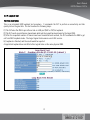
3-1-1 Login .......................................................................................................................................... 20
3-2 OLT ..................................................................................................................................................... 22
3-2-1 OLT VIEW .................................................................................................................................... 22
3-2-2 Port Config.................................................................................................................................. 25
3-2-3 OLT Statistics.............................................................................................................................. 26
3-2-4 OLT Information........................................................................................................................... 27
3-2-5 OLT Traffic Mgmt......................................................................................................................... 29
3-2-6 OLT Dynamic Bandwidth Allocation (DBA)...................................................................................... 31
2
User’s Manual
GEPON Chassis FK-C16
3-2-7 OLT IGMP Proxy........................................................................................................................... 37
3-2-8 Network Parameters.................................................................................................................... 46
3-2-9 OLT Operations............................................................................................................................ 47
3-2-10 Advanced Bridging Config........................................................................................................... 49
3-2-11 OLT Block Link List.................................................................................................................... 52
3-2-12 OLT All known Links................................................................................................................... 53
3-2-13 ONU List.................................................................................................................................... 54
3-2-14 ONU Authorization...................................................................................................................... 55
3-2-15 ONU Preprovision....................................................................................................................... 58
3-2-16 OLT Redundant .......................................................................................................................... 59
3-2-17 OLT Provision Wizard.................................................................................................................. 62
3-3 ONU .................................................................................................................................................... 63
3-3-1 ONU Subscriber View ................................................................................................................... 63
3-3-2 Port Config.................................................................................................................................. 66
3-3-3 ONU Statistics............................................................................................................................. 68
3-3-4 ONU Information.......................................................................................................................... 69
3-3-5 ONU Traffic Management ............................................................................................................. 71
3-3-6 ONU IGMP Snooping .................................................................................................................... 80
3-3-7 ONU Bridging Configuration.......................................................................................................... 85
3-3-8 ONU Misc Operations................................................................................................................... 89
3-3-9 Loopback Test............................................................................................................................. 91
3-3-10 ONU Provision Wizard................................................................................................................. 93
3-4 LOGICAL LINK ......................................................................................................................................... 94
3-4-1 Logical Link List.......................................................................................................................... 94
3-4-2 SLA ( Service Level Agreement ) ................................................................................................... 95
3-4-3 Multicast SLA.............................................................................................................................. 97
3-4-4 Bridge Mode Setting .................................................................................................................... 99
3-4-5 EPON Security........................................................................................................................... 103
3-4-6 Link Statistics........................................................................................................................... 104
3-4-7 Link Operation........................................................................................................................... 105
3-5 SYSTEM............................................................................................................................................... 106
3-5-1 System Information ................................................................................................................... 106
3-5-2 IP Configuration ........................................................................................................................ 109
3-5-3 System Time Configuration ........................................................................................................ 112
3-5-4 Account Configuration ............................................................................................................... 115
3-6 SNMP CONFIGURATION .......................................................................................................................... 116
3
3-7 ALARM ................................................................................................................................................ 118
3-7-1 Events Configuration.................................................................................................................. 118
3-7-2 Email Configuration................................................................................................................... 122
3-8 SOAK TIME CONFIGURATION ...................................................................................................................... 123
3-9 CONFIGURATION .................................................................................................................................... 124
3-9-1 Save/Restore............................................................................................................................. 124
3-9-2 Configure Export / Import File Path ............................................................................................ 125
3-9-3 Host/OLT/ONU Export Config Backup .......................................................................................... 127
3-10 DIAGNOSTIC........................................................................................................................................ 128
3-10-1 Diagnostic............................................................................................................................... 128
3-10-2 Ping Test................................................................................................................................. 128
3-11 TFTP SERVER..................................................................................................................................... 129
3-12 LOG DATA .......................................................................................................................................... 130
3-13 EPON LOG FILE .................................................................................................................................. 132
3-14 FIRMWARE UPGRADE ............................................................................................................................ 134
3-14-1 Host Firmware Upgrade............................................................................................................ 134
3-14-2 OLT Upgrade............................................................................................................................ 135
3-14-3 ONU Upgrade........................................................................................................................... 136
3-15 REBOOT............................................................................................................................................. 137
3-15-1 OLT Reboot Time...................................................................................................................... 138
3-16 LOGOUT ............................................................................................................................................. 139
CHAPTER 4 CLI MANAGEMENT ....................................................................................................................... 140
4-1 CLI MANAGEMENT ................................................................................................................................. 140
4-1-1 Login ........................................................................................................................................ 140
4-2 COMMANDS OF CLI ................................................................................................................................ 142
4-2-1 Global Commands of CLI............................................................................................................ 143
4-2-2 EPON Global Commands of CLI................................................................................................... 151
4-2-3 EPON Management Command of CLI........................................................................................... 155
APPENDIX A- EPON TECHNICAL SPECIFICATION .............................................................................................. 309
A-1 ONU DATA PATH CONFIGURATION .............................................................................................................. 309
A-1-1 Overview ................................................................................................................................... 309
A-1-2 Filtering, Classification, and Access Control ............................................................................... 309
A-1-3 ONU L2/L3/L4 Field Selector ...................................................................................................... 313
A-1-4 ONU Rule Setting Concept ......................................................................................................... 319
4
User’s Manual
GEPON Chassis FK-C16
A-1-5 ONU Bad Rule Example.............................................................................................................. 321
A-2 BRIDGING ............................................................................................................................................ 322
A-2-1 Introduction .............................................................................................................................. 322
A-2-2 MAC Address Learning ............................................................................................................... 322
A-2-3 ONU MAC Address Learning........................................................................................................ 323
A-2-4 OLT MAC Address Learning......................................................................................................... 324
A-2-5 Legacy Bridging Modes.............................................................................................................. 324
A-2-6 Bridge Mode Setting.................................................................................................................. 325
A-3 EPON DATA TRAFFIC ENCRYPTION .............................................................................................................. 337
A-4 IP MULTICAST ON EPON......................................................................................................................... 338
A-4-1 IGMP Snooping and Proxying...................................................................................................... 338
A-4-2 OLT IGMP PROXY ....................................................................................................................... 339
A-4-3 ONU IGMP Snooping .................................................................................................................. 341
A-4-4 IGMP CAC.................................................................................................................................. 343
A-4-5 FIFO selection and shaping ........................................................................................................ 344
A-5 SLA & DBA......................................................................................................................................... 345
APPENDIX B - TECHNICAL SPECIFICATION ...................................................................................................... 354
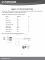
APPENDIX C - RS-232 SERIAL CABLE SPECIFICATION...................................................................................... 356
5
Caution
Circuit devices are sensitive to static electricity, which can damage their delicate electronics. Dry weather
conditions or walking across a carpeted floor may cause you to acquire a static electrical charge.
To protect your device, always:
Touch the metal chassis of your computer to ground the static electrical charge before you pick up the
circuit device.
Pick up the device by holding it on the left and right edges only.
Electronic Emission Notices
Federal Communications Commission (FCC) Statement
This equipment has been tested and found to comply with the limits for a class A computing device pursuant to
Subpart J of part 15 of FCC Rules, which are designed to provide reasonable protection against such interference
when operated in a commercial environment.
European Community (CE) Electromagnetic Compatibility Directive
This equipment has been tested and found to comply with the protection requirements of European Emission
Standard EN55022/EN60555-2 and the Generic European Immunity Standard EN50082-1.
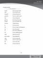
EMC:
EN55022(1988) /CISPR-22(1985)
EN60555-2(1995)
EN60555-3
IEC1000-4-2(1995)
IEC1000-4-3(1995)
IEC1000-4-4(1995)
class A
class A
4k V CD, 8kV, AD
3V/m
1kV – (power line), 0.5kV – (signal line)
6
User’s Manual
GEPON Chassis FK-C16
Chapter 1 Introduction
1-1 Overview
The intelligent box is a 19-inch EPON Media Converter Chassis with cabinet height 3U(5.20 inches). It is designed
to accommodate 16 slots of various type of EPON fiber media converter module at a central location for multiple
segments cross connection and network management. Any combination of EPON Fiber conversion solutions can be
installed in a wiring closet for cable connection. The network management supports Web UI via browser, CLI via
local console, Telnet interface and SNMPv2c. Supports IEEE 802.3ah OAM function for CO and CPE site “Remote
Failure Indication”, “Remote Loopback” and “Link Monitoring”. Supports “Port Configuration” and “Bandwidth
Configuration”. Models equipped with DC48V power unit are also available for Telecom applications.
Network management:
Built-in management board
Two 10/100 NWay Ethernet Port
One RS-232 port as local console
SNMP agent:
MIB-2 (RFC 1213)
Private MIB
Web browser support based on HTTP server
Telnet remote control CLI
TFTP software upgrade capability
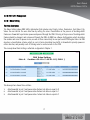
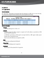
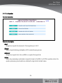
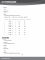
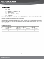
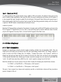
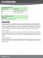
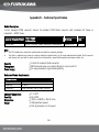
1-2 Model Description
Model
Power Supply Configuration
FK-C16-RAC
Two AC 100/240V Power
Module w/ Redundancy
DC Output
Slots
400W
@+12V
16
(200W each PS)
Table 1-1
Notes:
Each slot is equipped with a dummy panel as factory default
This chassis is compatible with the following modules/devices which are purchased in separate
o GEPON OLT Card Furukawa model FK-OLT-20 - installed on chassis slots (up to 16 cards per chassis)
o GEPON ONU Furukawa models FK-ONU-10 (10km) and FK-ONU-20 (20km) – CPE device
7
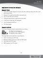
1-3 Checklist
Before you start installing the Converter Chassis, verify that the package contains the following:
16-Slot GEPON Chassis
Mounting Accessory (for 19" Rack Shelf)
This User's Manual CD-ROM
RS-232 Serial Cable (1pc)
AC power cord (2 pcs)
Please notify your sales representative immediately if any of the aforementioned items is missing or damaged.
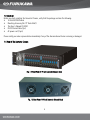
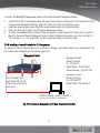
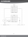
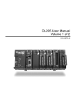
1-4 View of The Converter Chassis
Fig. 1-1 Front View of 19-inch Converter Chassis Rack
Fig. 1-2 Rear View of 19-inch Converter Chassis Rack
8
User’s Manual
GEPON Chassis FK-C16
Chapter 2 Installation
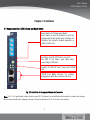
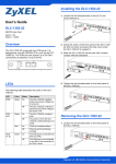
2-1 Management Board LED Indicator and Reset Switch
Reset Switch for Management Board:
Reset switch is used to initialize or reset the
management board system only, and does not
influence the converter module operation or
status of each slot.
Ear Phone Jack RS-232 Port for Local CLI.
Use DB9 to Ear Phone Jack cable when
connecting to COM port.
Link/Act LED (10/100 Port), Power and CPURUN
LED.
10/100 Port NWay Ethernet for In-Band
management with auto-crossover function.
Fig. 2-1 Front View of Management Board and Connector
Note: Port 1~2 is mainly used in daisy chain for each FK-C16 chassis, the switch/hub could be saved to connect each chassis
when the user would like to manage a variety of chassis mounted on the 19-inch rack in one network.
9
Rack ID (RID)
Chassis ID(CID)
Fig. 2-2 Front View of Rack ID and Chassis ID
Note: FK-C16 supports two sets of switch number for the chassis location definition, one is RID (Rack ID), and the other is
CID (Chassis ID). The former means the place in which the chassis was mounted in the Rack ID cabinet. The later means the
chassis’s number in the same rack cabinet. The RID and CID should be encoded when mounting the chassis into rack cabinet
according to telecomm room rack cabinet number.
10
User’s Manual
GEPON Chassis FK-C16
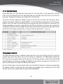
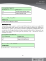
2-1-1 Power Module LED Indicator
Power A, B LED
LED
Color
Function
Power
Green
Lit when power is good
CPURUN
Green
Lit when CPU is active
LED for 10/100Mbps NWay Ethernet Port
Link/Act
Green
Lit when connection with remote device is good
Blinks when any traffic is present
LED for Redundant Power Unit A and Unit B
Lit when power unit A is good
Blinks when power unit A failed
Lit when power unit B is good
B
Green
Blinks when power unit B failed
LED A and B are steady lit when power redundancy takes effect with both A and B at
power-good status. It goes to simplex power (no redundancy) when either power unit
A or B failed with LED blinking. Unit A and unit B are hot-swappable.
A
Green
Table 2-1 LED Indicators Description and Status
2-2 Floor and Site Planning
16-Slot Intelligent Converter Chassis is designed in compliance with the EIA 310-D standards, and the chassis
cabinet height is 3U(5.2 inches). The power consumption of 16 modules (maximum loading) is up to 200 Watts.
11
Sufficient air ventilation and good environment are necessary to assure proper converter chassis operation.
Consider the proper spacing between the manageable chassis and adjacent facility when mounting the
manageable chassis to the 19-inch rails.
2-3 Installation
2-3-1 Installing Converter Chassis to a 19-Inch Wiring Closet Rail
Caution: Allow a proper spacing for the air intake at the bottom side, and proper air ventilation for the cooling fan at the rear
side of converter chassis.
Wear a grounding device for electrostatic discharge
Install four screws through mounting ears into each side
Locate Converter Chassis at 19-inch mounting rails and screw up the front brackets
Set power cord after power module inserted into the 16-slot chassis ready (for redundant power model, each
power unit has a separate power cord)
Verify that the voltage of AC power is correct and plug in AC power cord
Fig. 2-4 Installing Converter Chassis in 19-inch Wiring Closet Rails
2-3-2 Installing Management Board to a Converter Chassis
Note: Management board must be inserted in to slot M, it is hot-swappable.
Wear a grounding device for electrostatic discharge
Unscrew and remove the vacant slot M dummy panel
12
User’s Manual
GEPON Chassis FK-C16
Verify the management board is the right model and conforms to the chassis
Slide the management board along two guides in slot and fasten the thumb knob, and be sure that the
converter module is properly seated against the slot socket/connector
Install the media cable for network connection for converter chassis management
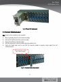
2-3-3 Installing OLT Converter Modules to a Converter Chassis
Note: Converter slide-in modules are hot-swappable.
Wear a grounding device for electrostatic discharge
Unscrew and remove the vacant slot dummy panel
Verify the converter module is the right model and conforms to the chassis
Slide the module along two guides in slot and fasten the thumb knob, and be sure
that the converter module is properly seated against the slot socket/connector
Install the media cable for network connection
Repeat the above steps, as needed, for each module to be installed into slot(s)
Power A
Power B
Slot 1~8 for
Converter Module
Slot M for
Management Board
Slot 9~16 for
Converter Module
Fig. 2-5 Installing All Module into the 16-slot Converter Chassis
13
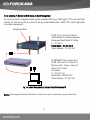
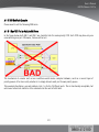
2-3-4 Installing PC Station for Web-Based, In-Band Management
The converter chassis management board provides embedded Web server, SNMP agent, TFTP client and Telnet
software, etc. that can be used at a remote PC with any installed Web browser, SNMP, TFTP or Telnet application
to do network management.
Management Board
10/100 TP port connects to Ethernet
switch/network for In-Band management
Management Board Default IP Setting:
IP = 192.168.1.1
Subnet Mask = 255.255.255.0
Default Gateway = 192.168.1.254
PC Web/SNMP Station equips with a
10/100 LAN board and connects to
Ethernet switch. Assign a unique IP
address for PC station.
For example:
IP = 192.168.1.146
Subnet Mask = 255.255.255.0
Default Gateway = 192.168.1.254
Fig. 2-6 In-Band Management by Ethernet Switch/Network and PC
Warning: Both management board and PC/station’s IP must be in a subnet, please assign a proper Subnet Mask.
14
User’s Manual
GEPON Chassis FK-C16
To connect the Web/SNMP Management module to the remote Network Management Station:
1.
2.
3.
4.
Locate CAT. 5e UTP (or up) network cable with male RJ-45 connector. Attach male RJ-45 connector to Media
Converter Rack Management Module. Attach the other end of cable to an Ethernet switch.
Locate the second network cable. Attach the second network cable to the Ethernet Switch.
Attach the other end of cable to the PC Network Management Station.
To assign a reasonable public or private IP address depends on each network site. Please refer to Figure 2-7
about the Converter Chassis Management board’s default IP address information. Also refer to Section 3-17-3 or Section 4-2-2 ” IP Configuration” for the management board’s IP address setting.
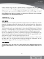
2-3-5 Installing a Terminal Emulator for CLI Management
The serial port cable is attached directly to a DTE device through a null modem cable for CLI management. The
null modem cable configuration is attached on Appendix C.
Management Board
Management board
Default IP Setting:
IP = 192.168.1.1
Subnet Mask = 255.255.255.0
Default Gateway = 192.168.1.254
Management Board
Default IP Setting:
IP = 192.168.3.177
Subnet Mask = 255.255.255.0
RS-232 Serial Cable
with female DB-9 to Ear
Phone Jack connector at
both ends
Attached Terminal, Terminal Emulator, or
PC running Hyper Terminal for CLI Management
Fig. 2-7 Local Console Management by PC Hyper Terminal and Com Port
15
To connect the Management board to the CLI interface:
1.
2.
3.
Locate the correct DB-9 serial port null modem cable with female DB-9 connector. Refer to the Appendix C
for null modem cable configuration. Null modem cable comes with the management chassis.
Attach the DB-9 serial port female cable connector to the male DB-9 serial port connector on the Converter
Chassis Management board.
Attach the other end of the DB-9 serial port cable to an ASCII terminal emulator. For example, Windows98’s
HyperTerminal utility.
Note: The Management board uses the following serial port parameter values:
Baud rate
57600
Stop bits
1
Data bits
8
Parity
N
Flow control
none
4.
5.
When the terminal emulator connected the management board, then press <Enter>key, the Login prompt will
be shown on the screen. The default username and password are shown as below:
Username = admin
Password = admin
Refer to Chapter 4 “CLI Management” for more details.
2-4 Maintenance and Replacement
2-4-1 Power Unit Replacement
Note: For redundant power model, the power unit LED will blink when power unit failed.
Wear a grounding device for electrostatic discharge
Remove power cord from power connector (AC socket / DC terminal block)
Unscrew the power unit
Remove the defective power unit
Slide-in the replacement power unit along the guide rails
Install and fasten the power unit
Install power cord onto power connector
16
User’s Manual
GEPON Chassis FK-C16
Fig. 2-8 Power Unit Replacement
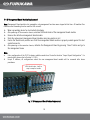
2-4-2 Converter Module Replacement
Note: Converter slide-in modules are hot-swappable
Wear a grounding device for electrostatic discharge
Unscrew the thumb knob of the converter module
Remove the defective converter module
Slide the replacement converter module along two guides in slot
Fasten the thumb knob, and be sure that the converter module is properly seated against the slot
socket/connector
With thumb knobs, it will be
easy to swap the module
Fig. 2-9 Converter Module Replacement
17
2-4-3 Management Board Module Replacement
Note: Management Board module is hot-swappable; only management functions were stopped at that time. All modules fiber
conversion and forwarding function could be still run well.
Wear a grounding device for electrostatic discharge
After powering off the converter chassis, unscrew the thumb knob of the management board module
Remove the defective management board module
Slide the replacement management board module along two guides in slot
Fasten the thumb knob, and be sure that the management board module is properly seated against the slot
socket/connector
After powering on the converter chassis, initialize the Management Board by pressing “Reset” button and go to
the management menu
Note:
Entire configuration of the FK-C16 chassis could be saved into a file via the function "Import Export Configuration". For
more details, please refer to Section 3-1-10-5.
Except IP address, all configurations about the new management board module will be recovered after above
procedures.
With thumb knobs, it will be
easy to swap the module
Fig. 2-10 Management Board Module Replacement
18
User’s Manual
GEPON Chassis FK-C16
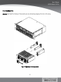
2-4-4 High Speed Fan
Attention: High Speed Fan Exchange! Please watch your own safety during swapping if the fan is still running.
Fig. 2-11 High Speed Fan Replacement
19
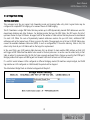
Chapter 3 Web-based Management
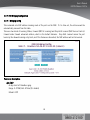
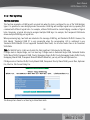
3-1 Web-Based Management, In-Band Management
Refer to Chapter 2 for basic installation. The following description is the brief of the network connection.
For Management Board: 10/100 TP port connects to Ethernet switch/network for In-Band management.
Management Board Default IP Setting:
IP = 192.168.1.1
Subnet Mask = 255.255.255.0
Default Gateway = 192.168.1.254
For PC Web/SNMP Station: Install a 10/100 LAN board and connect to Ethernet switch. Assign a unique IP
address, for example:
IP = 192.168.1.146
Subnet Mask = 255.255.255.0
Default Gateway = 192.168.1.254
Warning: Both PC/station and management boards’ IP must be located in the same IP subnet, please assign a proper Subnet
Mask.
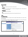
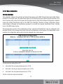
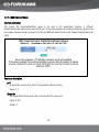
3-1-1 Login
Run Internet IE Browser V4.0 or above, then go to http://192.168.1.1/
Default Username: admin Default Password: admin
20
User’s Manual
GEPON Chassis FK-C16
Caution:
If the default IP address (192.168.1.1) is not available, you can use CLI management’s IP setting (refer to Chapter 2 and
Chapter 4) to configure a suitable IP address for the management access.
If the IP address conflict occurred, the “Login Menu” would not be accessed. The installer must resolve the IP address
conflicts to access the “Login Menu”.
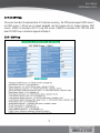
The main function list will be displayed on the left side of the screen
21
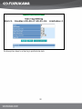
3-2 OLT
This CO site Chassis supports up to 16 OLT modules.The management functions about OLT modules are described
in this section.
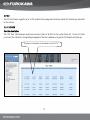
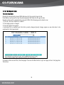
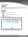
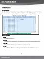
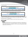
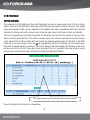
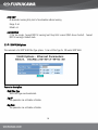
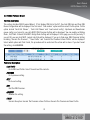
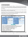
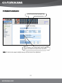
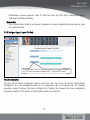
3-2-1 OLT VIEW
Function description:
The “OLT View” table displays model name and port status of all OLTs in the system (from slot 1 to slot 16). Click
on a row in this table,the corresponding management function submenu of a specific OLT module will show up.
Display the information of all modules in the FK-C16.
22
User’s Manual
GEPON Chassis FK-C16
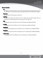
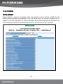
Parameter description:
Slot:
Slot Number of each row in this table. Slot 1 is the most left module slot of the physical chassis; slot 16 is
the most right one. An empty row (a row without any status data) represents a slot without OLT plugged in.
Model Name:
The model name of the OLT module in a specific slot.
Link Status:
The physical link status of the CNI port of an OLT. Possible values are [Up] and [Down]. CNI is the
abbreviation of “Core Network Interface”. Other synonyms are “SNI”,”uplink port”.
State:
The management status of the CNI port on an OLT. Possible values are [Enable] and [Disable].
Auto Nego.:
Auto Negotiation status of the CNI port on an OLT. Possible values are [Enable] and [Disable] .
Speed/Duplex:
Current line speed and duplex mode of the CNI port on an OLT. Possible values are [1000/Full][100/Full].
Flow Control:
IEEE802.3x Pause flow control state of the CNI port on an OLT. Possible values are [Enable] and [Disable] .
EPON Port State:
The management status of the EPON port on an OLT. Possible values are [Enable] and [Disable].
23
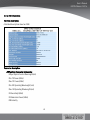
Click the slot module, and a selection list will be pop up. User can
choose one of them to view or configure the setting for this module.
24
User’s Manual
GEPON Chassis FK-C16
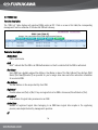
3-2-2 Port Config
Function description:
Configuration port settings for both CNI and EPON ports on an OLT. <Default> button would load the factory
default settings to the dialogue box. Configuration values will take effect until <Apply> button is clicked.
Parameter description:
State:
To configure the management status of both CNI and Epon ports on an OLT. Possible values are [Enable]
and [Disable].
Default: [Enable]
Auto Nego.:
To configure Auto Negotiation state of the CNI ports on an OLT. Possible values are [Enable] and [Disable]
Default: [Enable]
Speed/Duplex:
To configure line speed and duplex mode of the CNI ports on an OLT. Possible values are
[1000/Full][100/Full].
Default: [1000/Full]
Flow Control:
To configure flow control state of the CNI port of an OLT. Possible values are [Enable] and [Disable]
Default: [Disable]
25
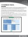
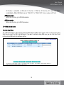
3-2-3 OLT Statistics
Function description:
Requests statistics related to the specified ports including Epon port and CNI port. The transferring direction
supports upstream and downstream. If you click Refresh button, the statistics information will be displayed. If
Clear button is clicked, the statistics information will be cleared. Upstream direction reflects the traffic from
Epon port to CNI port. Downstream direction reflects the traffic from CNI port to Epon port.
26
User’s Manual
GEPON Chassis FK-C16
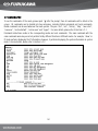
3-2-4 OLT Information
Function description:
A detailed description about an OLT.
Parameter description:
OLT optical Transceiver information:
Output Optical Center Wavelength(nm)
Min. TX Power (dBm)
Max. TX Power (dBm)
Min. RX Operating Wavelength (nm)
Max. RX Operating Wavelength (nm)
RX Sensitivity (dBm)
RX Saturation Power (dBm)
OLT identity
27
Mac Address:
The globally unique Mac Address of an OLT. The Mac Address is primarily used within an EPON system to
identify the OLT.
Firmware Version:
The version number of the (app )firmware currently running on the OLT EPON chip.
Chip ID:
The EPON chip type of the OLT.
Chip Version:
The hardware version number of the EPON chip inside the OLT.
Boot Code Version:
The firmware version number of the bootstrap code residing in the OLT EPON chip.
Personality Version:
Personality is an area in the flash memory inside the OLT.This non-volatile memory keeps the most basic
and default provisioning information of an OLT. When an OLT boots up,some provisioning information must
be fetched from the personality area.
App0 Version:
App1 Version:
Two memory areas are allocated within the OLT flash for the redundant storing of the EPON application
firmware. App0 is the primary one.If app0 is crashed and unable to be loaded, app1 will be the
backup.When one application firmware load crashing is detected,the backup load will be automatically
replicated to keep the redundancy.
28
User’s Manual
GEPON Chassis FK-C16
3-2-5 OLT Traffic Mgmt
3-2-5-1 OLT Filter
Function description:
Setting OLT Filter can add a new filter rule to the OLT. Deleting OLT Filter is the symmetrical operation used to
remove an existing filter rule. Multiple filter conditions (clauses) may be specified in a single rule, in which case
the conditions are considered to be logically ANDed together to determine how the rule takes effect. Rules that
are specified using separate messages are considered to be logically ORed. A series of conditions ORed together
would be specified as several independent filter rules with the same action for each. Rules are applied to frames
in the upstream or the downstream direction, and a specified action is executed when a match occurs. A rule can
match a field in a frame against a Lookup value with a given operator.
The Set and Delete OLT Filter command is used to set or delete a single filter rule. Multiple uses of the
commands must be used to set or delete multiple filter rules. However the Get command will return all of the
filter rules currently provisioned. While specifying an OLT Port Filter, the maximum number of clauses is 8. About
specifying an OLT Link Label Filter, the maximum number of clauses is 7.
If you click “OLT link Filter” button,OLT Link
Filter Information will be displayed
If you click Add button,
yot can add filter rule. The
rule setting may be
referred to 3-3-5 ONU
Traffic Management.
29
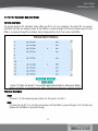
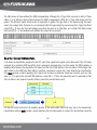
3-2-5-2 OLT Dynamic Table
Function description:
Display the automatically learned MAC addresses for the selected Logical Link.
Clear Button can be used to clear the whole dynamic MAC table for all Logical Links.
Dynamic entries will be automatically removed if ANY of the following events should occur:
1. The link’s SLAs are disabled or enabled
2. The bridging mode is changed
3. The link departs the network
4. Upstream SLA is modified such that link’s priority changes (priority change requires a new link index to be
registered for that logical link).
If dynamic entries exceed 256, It has two pages. You can click Next button to get next page entries. Each page has
256 entries.
30
User’s Manual
GEPON Chassis FK-C16
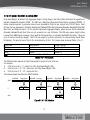
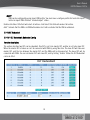
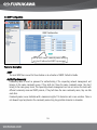
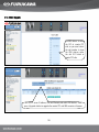
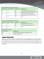
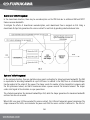
3-2-6 OLT Dynamic Bandwidth Allocation (DBA)
Drop Down Weight, Broadcast SLA, Aggregate Shaper, Priority Range, and Polling Rate determine the operation of
Dynamic Bandwidth Allocation (DBA). The DBA use a Weighted Hierarchical Round Robin scheduler (WHRR). It
allows network operator to provision Service Level Agreements (SLAs) on per Logical Link ID (LLID) basic. Each
SLA has the four parameters, Minimum Guaranteed Bandwidth (Min Bw), Maximum Allowable Bandwidth (Max Bw),
Burst Size, and Delay Tolerance. On the system implements Aggregate Shaper, which ensures that the Maximum
Allowable Bandwidth and Burst Size are not exceeded on a per SLA basis. The DBA uses queue length status
received from ONU Report messages, along with the SLA parameters, to calculate bandwidth allocation. There are
up to 3 levels of hierarchy support. Each LLID can maps to a priority level and it is serviced using Round Robin
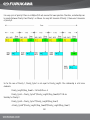
Scheduling. The priority level of the LLID is determined by its SLA. The 3 levels show as below. (Table 3-2-6-1)
Priority Level
Delay Sensitive
Min Bw / Max Bw
0 (high)
Sensitive
Max Bw = Min Bw
1 (medium)
Tolerant
Min Bw > 0
2 (low)
Tolerant
Min Bw = 0
Note: If the delay sensitive is “Sensitive”, but the Min Bw and Max Bw are not the same, this setting is Invalid.
Table 3-2-6-1 Priority Level
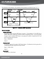
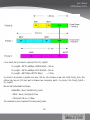
The DBA Scheduler depends on Drop Down weight to give next level total size.
For example:
LLIDs of Level 0: 0 ~ 9 < token size: 2K / Drop Down Weight: 20K >
LLIDs of Level 1: 10 ~ 20 < token size: 4K / Drop Down Weight: 20K >
LLIDs of Level 2: 21 ~ 29 < token size: 8K >
The below diagram illustrates the DBA Scheduler.
llid0-llid9
L 0 2K
…
Drop Down
20K
L1
llid10-llid14
4K
llid0-llid9 Drop Down
2K …
20K
llid15-llid19
4K
llid0-llid9
2K …
Drop Down
20K
llid20 &
Drop Down
4K
16K
Llid21-llid22
8K 8K
L2
Figure 3-2-6-1 DBA Scheduler
31
llid0-llid9
2K …
Drop Down
20K
llid10-llid14
4K
3-2-6-1 DBA Drop Down Weight
The Downstream direction needs to configure the Drop Down Weight.
Range: 0~ 256 (Units: KBytes)
Default: 4
32
User’s Manual
GEPON Chassis FK-C16
3-2-6-2 Broadcast SLA
This parameter is SLA of using in Broadcast Link. This set DBA Priority Range should only be performed on a
disabled OLT with no links registered.
Parameter description:
Maximum Allowed Bandwidth (Max Bw)
Range: 256~1000000
Default: 1000000
Minimum Guaranteed Bandwidth (Min Bw)
Range: 256~1000000
Default: 1000000
Max Burst:
Range: 1~256
Default: 100
33
3-2-6-3 Aggregate Shaper
This command can control overall bandwidth for user traffic in upstream and downstream. When this parameter
is set 0. That means the Aggregate Shaper is disabled. This command is disabled by default. If Maximum Allowed
Bandwidth or Max Burst is 0, this function is disabled.
Parameter description:
Maximum Allowed Bandwidth (Max Bw)
Range: 100~1000000
Default: 0
Max Burst:
Range: 0~256
Default: 0
34
User’s Manual
GEPON Chassis FK-C16
3-2-6-4 Priority Range
This command can set how many Logical Links in the priority Level. That set Priority Range should only be
performed on a disable OLT with no links registered. The Priority Level illustrates as Table 3-2-6-1. The Level 0
and Level 1 can be set to 0, but Level 2 must more than 0. The sum of all Priority Range should add up to no more
than 239.
Parameter description:
Level 0:
Range: 0~238
Default: 32
Level 1
Range: 0~238
Default: 128
Level 2
Range: 1~239
Default: 64
35
3-2-6-5 Polling Rate
This command can set DBA Polling rates for the three levels. Registered links in Active scheduler levels must be
provisioned with a non-zero polling rate. If the parameter is set as zero, that means scheduler level is disabled.
This parameter can be set in increments of 65.5 usec.
Parameter description:
Level 0
Range: 0~256
Default: 15
Level 1
Range: 0~256
Default: 15
Level 2
Range: 1~256
Default: 61
36
User’s Manual
GEPON Chassis FK-C16
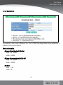
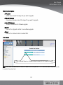
3-2-7 OLT IGMP Proxy
This session describes the implementation of IP multicast processing. The EPON system supports IGMP version 1
and IGMP version 2, efficient use of network bandwidth, and fast response time for channel changing. IGMP
version 1 (IGMPv1) is described in RFC1112 ,and IGMP version 2 (IGMPv2) is described in RFC 2236. The detail
about OLT IGMP Proxy is attached on Appendix A Chapter 5.
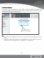
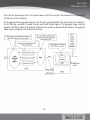
3-2-7-1 IGMP Proxy
37
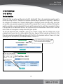
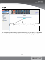
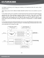
This command has many parameters. The relationship of these parameters are detailed in Figure 3-2-7-1-1.
Interval
Timeout
Timeout
OLT
Report
Query
ONU
Report
Query
Query
Query
Report
Report
USER
Maximum Response Time
Maximum Response Time
Propagation and processing delay
Figure 3-2-7-1-1 Relationship of IGMP Proxy parameters
Parameter description:
Maximum IGMP Groups:
This parameter means how many IGMP Groups can support. If this parameter is 0, the IGMP Proxy is
disabled. When IGMP is disabled, all IP Multicast Frames are forwarded by the OLT. If the current number
of groups is equal to maximum IGMP Groups, no new groups will be added or forwarded by the OLT, and
joins for new groups will be discarded.
Range: 0~4096 (0=OFF)
Default: 0
Robustness Count:
This parameter represents the number of IGMP General Queries. The Robustness Count may pass with no
corresponding IGMP Report reply before a Group is removed.
Range: 1~16 (Unit: 10ms)
Default: 2
Query Interval:
This parameter is a time interval.
38
User’s Manual
GEPON Chassis FK-C16
Range: 12~65535 (Unit: 10ms)
Default: 12500
Query Response Timeout
This parameter is the OLT waits for IGMP Reports after sending a General IGMP Query. If the timer expires,
and the Group does not receive a report, then the Robustness counter is decremented.
Range: 11~65534 (Unit: 10ms)
Default: 1001
Query Message Maximum Response Time
This parameter is the actual value set in the Maximum Response Time field of IGMP General Query
messages sent down stream by the OLT. The Query Message Maximum Response Time must lower than
the Query Response Timeout.
Range: 1~255 (Unit: 100ms)
Default: 100
Start Query Count
If IGMP is enabled or reset, the OLT uses Startup Queries initially. The Group memberships are quickly
established after initialization.
Range: 0~16
Default: 2
Start Query Interval
This interval must lower than the regular IGMP General Query Interval.
Range: 12~65535 (Unit: 10ms)
Default: 3125
39
Last Member Query Count
This parameter is the number of IGMP Group Specific Queries sent when an IGMP Leave message is
received for a specific Group. If this count is 0 and Last Member Query Interval expires, the multicast
group is removed, multicast traffic forwarding for the group is stopped.
Range: 0~16
Default: 2
Last Member Query Interval
This parameter is an interval, which IGMP Group Specific Queries are sent. The Last Member Query Interval
higher than the Last Member Query Maximum Response Time.
Range: 11~65535(Unit: 10ms)
Default: 110
Last Member Query Message Maximum Response Time (Last Member Query Message Max. Resp. Time)
The Last Member Query Message Maximum Response time set in the Maximum Response Time filed of
IGMP Group Specific Query messages sent downstream. This value must be lower than the Last Member
Query Interval.
Range: 1~255 (Unit: 100ms)
Default: 10
Retransmit Count
Range: 0~3
Default: 0
Retransmit Interval
This is an interval, which represents the interval at which IGMP Reports (Joins) are retransmitted
upstream.
Range: 1~65535 (Unit: 10ms)
Default: 1000
40
User’s Manual
GEPON Chassis FK-C16
VLAN Tag (CoS)
This parameter is a fixed VLAN tag. It is added into IGMP Messages generated by the OLT and strip VLAN
tags off of multicast traffic on a specific VLAN.
Range: 0~7
Default: 0
VLAN Tag (VID)
Range: 0~4094
Default: 0
Num. Multicast Queues
If IGMP is enabled, the multicast data flow has Queues of “Num. of IGMP queues”.
Range: 1~10
Default: 4
IGMP Frame checksum validation
This parameter can set IGMP Frame checksum validation. It has two modes, Enable and Disable.
Default: Disable
IGMP IP Header checksum validation
This parameter can set IGMP IP Header checksum validation. It has two modes, Enable and Disable.
Default: Disable
41
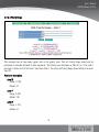
3-2-7-2 IGMP SLA
This command can control multicast SLA. It is in effect when the IGMP Proxy is enabled. This command has four
parameters, Maximum Allowed Bandwidth, Minimum Guaranteed Bandwidth, Max Burst, and delay sensitive
(mode). If the delay sensitive is “Sensitive”, but the Min Bw and Max Bw are not the same, this setting is Invalid.
Parameter description:
Maximum Allowed Bandwidth (Max Bw)
Range: 256~1000000
Default: 100000
Minimum Guaranteed Bandwidth (Min Bw)
Range: 0~1000000
Default: 100000
Max Burst
Range: 1~256
Default: 100
Delay sensitive (Mode)
This parameter has two modes, Sensitive and Tolerant.
42
User’s Manual
GEPON Chassis FK-C16
3-2-7-3 IGMP VLAN
This command can configure the VID and bandwidth for the IPMC. There are 8 groups can be set. The Network
VLAN Tag is used on the frame of uplink side on the OLT. The EPON VLAN Tag is used for the downstream of the
OLT. Thus the command can add tag, strip tag, retain tag, or replace tag. Every Group must set Min Bandwidth,
Max Bandwidth, and Default Per-Channel Bandwidth.
Parameter description:
43
Network VLAN TAG / EPON VLAN TAG - Cos
Range: 0~7
Default: 0
Network VLAN TAG / EPON VLAN TAG - VID
Range: 0~4094
Default: 0
Min Bandwidth
Range: 0~1000000
Default: 0
Max Bandwidth
Range: 0~1000000
Default: 1000000
Default Per-Channel Bandwidth
This parameter means per channel give a default bandwidth.
Range: 0~1000000
Default: 0
44
User’s Manual
GEPON Chassis FK-C16
3-2-7-4 IGMP Group
This command can show all IGMP group status for each VLAN or all VLAN. The List represents the Group IP of
Group VLAN, and how many bandwidths it has.
45
3-2-8 Network Parameters
Function description:
A Dialogue box for configuring some OLT-specific network parameters. These parameters are divided into four
portions: OAM Parameters, Ether Type parameter, MPCP parameters and Autonomous Message Control.
Parameter description:
OAM Parameters:
Max OAM Rate(PDU/sec)
Total OAM PDU transmission per second per logical link is limited to the Max OAM Rate specified. A value
of zero disables the limit and allows an unlimited number of OAM frames on a logical link.
Default: 10 (PDUs/sec)
Min OAM Rate(sec/PDU)
One OAM Information PDU are generated at Min OAM Rate,if no other OAM PDU is transmitted for the
defined length of time. OAM link failure occurs when five minimum OAM intervals have passed with no OAM
message received.
Default: 1 sec
Loopback Timeout(100 msec)
46
User’s Manual
GEPON Chassis FK-C16
The loopback failsafe timeout value. A port or a logical link on an ONU which is commanded to get into
loopback mode will remain in this state until receiving the OAM “Loopback Disable” command, or until this
timer expires.
Default: 600
Additional Ether Type parameters:
The firmware of the OLT uses the default Ethertype of 0x8100 to identify frames with VLAN tags. For the
interoperability in some special application using VLAN, an additional Ethertype to identify VLAN frames may be
defined here.
VLAN Ether Type
The additional Ether Type to specify
Default: 0x8100
Tag Up
Use the VLAN Ether Type Specified above to tag upstream
Default:[Disable]
Tag down
Use the VLAN Ether Type Specified above to tag downstream
Default:[Disable]
MPCP parameters
The parameters for the MPCP(IEEE802.3ah, clause 64 - Multi-point Mac Control Protocol) discovery
process.
Discovery Period(10ms)
The period of time for the OLT to generate a discovery gate.
Default:100 (=1 Second)
Discovery Window
The size in byte of the MPCP discovery window in a EPON system
Default: 16319
3-2-9 OLT Operations
47
Function description:
Parameter description:
Enable OLT
Enable OLT to pass user traffic
Disable OLT
Disables the OLT, turning off the EPON port and blocking both upstream and downstream traffic.
Reset OLT
Reboot OLT
Restore OLT
Erase all provisioning records of Non-Volatile Store (NVS) and reboot the OLT. This operation returns the
operator provisioning database to default values.NVS is an area of flash memory inside the OLT.The
provisioning database of the OLT and its subordinate logical links are kept in this Non-Volatile Store. It
includes OLT Traffic Management, OLT Advanced Bridging Config, OLT DBA(Drop Down Weights, Priority
Range, Polling Rate, Aggregate Shaper, Broadcast SLA), OLT IGMP Proxy, All Logical Link Bridge Mode, SLA,
Multicast SLA).
Config
Export OLT Config File -The provisioning database of the OLT can be exported out as a computer file.
Import OLT config File -This file can be used when provisioning database recovery or replication is needed.
48
User’s Manual
GEPON Chassis FK-C16
It includes OLT Traffic Management, OLT Advanced Bridging Config, OLT DBA(Drop Down Weights, Priority
Range, Polling Rate, Aggregate Shaper, Broadcast SLA), OLT IGMP Proxy, Network Parameters, Port Config,
All Logical Link Bridge Mode, SLA, Multicast SLA).
3-2-10 Advanced Bridging Config
3-2-10-1 Advanced Bridging Config : General Setting
Function description:
Advanced Bridging Config include Age Limit, Number of Bridged Vlans, Downstream Frame Reset Age, Mac Learing
overwrite, Discard Unknown MAC ,and Allow Vlan Tag on Simple Bridge.
49
Parameter description:
Age Limit
Learned entry age limit, Min value is 0. Max value is 32768.
Default: 0
Number of Bridged VLANs
Min value is 0. Max value is 24.
The “Number of bridged VLANs” must be greater than or equal to the number of unique VLAN tags
configured in a shared bridging mode.
Default: 24
Downstream Frames Reset Age
Frames received by the OLT LNP port reset the learned entry age value for dynamic entries based on DA of
incoming frame. In this mode upstream frames will also reset the age value based on SA as normal.
Default: disable
MAC Learning overwrite
Controls how SA Learning behaves after the per-link Learning table is full. This option is set to 1 to
overwrite the oldest learned entry in favour of a new MAC.
Default: disable
Discard unknown MAC
When set to 1 will cause the OLT to drop downstream frames with unknown DAs (i.e. it does not forward on
the Broadcast link).
Default: disable
Allow Simple Bridging
Affects the number of Bridged VLANs parameter. (Currently must set to 1)
Default: enable
50
User’s Manual
GEPON Chassis FK-C16
3-2-10-2 Advanced Bridging Config : Priority Copy Config
Function description:
This command sets up the priority conversion table on the OLT for the priority remapping VLAN modes (e.g. Priority
Remapping Single VLAN). When a logical link is in a Priority Remapping based VLAN mode, the OLT looks at a
specified priority value in the upstream frames and adds a VLAN tag with a COS from the mapping table.
The Priority Mode A/B is a 16-bit value that selects what priority field to lookup in the input frame. Currently the
values 0x1545 for Mode A (to select IP-TOS) and 0x1743 for Mode B (to select COS) may be used. The precedence
field selects which priority mode (s) to use and in what order. In case the upstream frame does not match the
given priority modes, the OLT outputs a default COS value.
As an example, the command, {Priority Mode A = 0x1545; Priority Mode B = 0; Precedence = 0; Default COS = 0;
N=8 (1, 1, 2, 2, 3, 3, 4, 4); M = 0} maps TOS values [0, 1] to COS 1, TOS [2, 3] to COS 2 etc. When there is no TOS
in the input frame (non-IP frame), the COS value is 0. Priority Mode B is not used in the example and the empty
table for Priority Mode B is indicated by setting M = 0.
51
3-2-11 OLT Block Link List
Function description:
Shows a the list of Logical Links that were manually blocked. To unblock a blocked logical link,just select an
entry and use [Unblock Link] option to do so.
Parameter description:
Link Label
Mac Address of the blocked logical link.
52
User’s Manual
GEPON Chassis FK-C16
3-2-12 OLT All known Links
Function description:
Retrieves the list of all logical links configured at the OLT. The logical links displayed include links that have any
kind of provisioning,links that were discovered and currently not registered.Provisioning logical links that are not
physically connected to an OLT is possible through this window.
Parameter description:
Link Label
Mac Address of a logical link known to the selected OLT.
Status
The status of a logical link.Possible values are Blocked or Registered.
Bridge, Vlan
Refer to Logical Link Bridge, Vlan Tag.
53
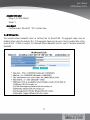
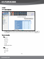
3-2-13 ONU List
Function description:
The “ONU List” table displays all registered ONUs under an OLT. Click on a row in this table,the corresponding
management function submenu of the selected ONU will show up.
Parameter description:
Model Name
ONU’s model name.
Auth
Auth * indicate that the ONU is in ONU Authorization List. Auth v indicate that the ONU is authorized.
User Name
Every ONU has a globally unique Mac Address. User Name is alias of the Mac Address.Three buttons ([Edit
Name] [Del Name][Unselect]) are provided for you to assign alias name and other subscriber information
for a selected ONU.
Mac Address
The Mac Address is the unique identity of an ONU.
Registered
Possible values are [Yes] or [No]. If any one logical link of an ONU is discovered,this attribute is [Yes].
All Links #
Total number of logical links provisioned on an ONU.
Active Links
Number of registered logical links belonging to an ONU.Some logical links maybe in the registering
process,some maybe blocked by management operation.
RF
54
User’s Manual
GEPON Chassis FK-C16
RF Module is embedded in ONU with RF function. If ONU has RF function, RF status can display
enable/disable. When ONU Model name is "ONU-E101" or "ONU-E101A", there is a value in RF field.
ONU Authorization
When click the item, go to ONU Authorization.
ONU Preprovision
When click the item, go to ONU Preprovision.
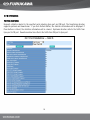
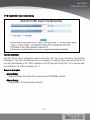
3-2-14 ONU Authorization
Function description:
The “ONU Authorization” table displays Authorized/Unauthorized ONUs under an OLT. Click on Select field in this
table,You can select the ONU to be authorized. If you want to authorize many ONU once, you can click Select field
in the selected ONU and click Authorize button.
55
Parameter description:
Mac Address
The Mac Address is the unique identity of an ONU.
All Link #
Total number of logical links provisioned on an ONU.
Status
The status displayed on the ONU. It include “Registered” and “ ”. “Registered” represent ONU on line. “ ”
represent ONU not Registered.
Mark
Authorize will check Link # and ONU Link number. If conflict, Mark field will be *.
Authorization
It include Yes and No. After ONU is authorized, ONU SLA can be enabled. You can select item with clicking
Select field and click Authorize button. All ONU want to have service and you must let ONU be authorized
first.
Profile
ONU configuration file. You can import the profile and let ONU has the profile setting.
Authorize
You can select ONU with clicking Select field and click Authorize button. The on line ONU must be
authorized and can have service. The unauthorized ONU will have no bandwidth.
UnAuthorize
You can select ONU with clicking Select field and click UnAuthorize button. The unauthorized ONU will have
no bandwidth.
56
User’s Manual
GEPON Chassis FK-C16
Parameter description:
Refresh
The ONU Authorization display don’t reflect the current state sometimes. You must click refresh button to
display the current state.
Add ONU
If a new ONU is added to EPON system, you can click “te ONU” button to add ONU mac address to
Authorization List and can operate on ONU.
Del ONU
Del ONU means that Del ONU from Authorization List.
Apply Profile
Edit Authorization profile. ONU can be configured by using a “ONU configuration” profile. Once you set ONU
profile name O.K., you can go to ONU Provision to import profile to ONU.
57
3-2-15 ONU Preprovision
Function description:
The “ONU Preprovision” table displays all known ONUs under an OLT. Click on a row in this table,the
corresponding management function “Logical Link List” submenu of the selected ONU will show up.
Parameter description:
Refresh
The ONU Preprovision display
Add to List
Add selected ONU to Authorization List. The Authoriaztion List can be used to authorize/unauthorize ONU.
Create ONU
Create one ONU for ONU Preprovision. The ONU can be set Bridge Mode, SLA.
Del ONU
Del one ONU from ONU Preprovision. The Logical Link Bridge Mode, SLA in the ONU will be removed.
58
User’s Manual
GEPON Chassis FK-C16
Import
ONU can be configured by using import ONU profile. You must save a configure profile first and click import
button to import ONUs that has “checked import” status .
Double click Select title field will select all entries. click Select title field will unselect all entries.
Auth * indicate that the ONU is in ONU Authorization List. Auth v indicate that the ONU is authorized.
3-2-16 OLT Redundant
3-2-16-1 OLT Redundant : Redundant Config
Function description:
The section discribes two OLT can be redundant. One OLT is set to be master OLT, another is set to be slave OLT.
When the master OLT is broken or can’t be connected with ONUs by using fiber line. The slave OLT will take over
master OLT, and the line between the master OLT and the ONUs will be disconnected. The slave OLT will be
connected with ONUs. You can set master OLT and slave OLT, and by Setting “Enable” Status the OLT Redundant
can be in effect.
59
Parameter description:
Status
It include Enable and Disable. If Enable, the OLT redundant function is in effect. If Disable, The OLT
redundant doesn’t work.
Master OLT
When two OLTs are set redundant enabled. The master OLT is at work, and the slave OLT is a backup OLT.
If master OLT is broken, the slave OLT will take over the master OLT. The original slave OLT will be changed
to the master OLT. The original master OLT will be changed to slave OLT. Now you can remove the broken
OLT and insert the healthy OLT.
Slave OLT
When two OLTs are set redundant enabled. The master OLT is at work, and the slave OLT is a backup OLT.
The above figure displays eleventh OLT is Slave OLT. If sixth OLT is broken, the eleventh OLT will be
changed to the master OLT.Note that “Auto Change” need to be set on and the slave OLT can be changed to
master OLT.
Auto Change
If Auto Change on, the master OLT and the slave OLT switch is automatically changed. If Auto Change off,
the master OLT and the slave OLT switch is not automatically changed.
Dual Write
If Dual Write on, you set commands to ONU by way of the master OLT and at the same time the slave OLT is
set also. If Dual Write off, you set commands to ONU only by way of master OLT. The slave OLT is not be
set.
Sync. OLT
After enable OLT redundant, you must remember to sync OLT. “Sync OLT”
means the master config is set to the slave OLT. When redundant enabled, the master and the slave OLT
config must be the same.
60
User’s Manual
GEPON Chassis FK-C16
3-2-16-2 OLT Redundant : Redundant Status
Function description:
The section discribes OLT redundant status. When two OLT is set to be redundant, the master OLT can connect
with ONUs. The fiber line between master OLT and ONUs is passed through. The fiber line between slave OLT and
ONUs is not passed through.The redundant status display whether the OLT can connect with ONUs.
Parameter description:
Group
It include 1 ~8. The maximum group number is 8. The group 1 is 6 and 11.
State
It include On and Off. If on, the fiber line between OLT and ONUs is passed through. If off, the fiber line
between OLT and ONUs is not passed through.
61
3-2-17 OLT Provision Wizard
Function description:
The section discribes OLT Provision Wizard. You can set OLT DBA Drop Down Weights, DBA Polling Rate ,DBA
Priority Range and Advanced Bridging Config. If you select “Load Default”and click Run button, the default OLT
setting will be displayed. If you select “Load from other OLT” and then select Source Slot and click Run button,
the other OLT setting will be displayed. If you select “Load from profile” and click Run button, the profile setting
will be displayed.
62
User’s Manual
GEPON Chassis FK-C16
Parameter description:
Load
It include Load Default, Load from other OLT, Load from profile.
Source Slot
When you select “Load from other OLT” , the Source Slot setting will be in effect. Click Run button and
Source Slot setting will be loaded.
Destination Slot
The setting wiIl be set in Destination.
Run
Before clicking the Run button you wiIl need to select Load option and Source Slot.
3-3 ONU
3-3-1 ONU Subscriber View
List ONU that has subscribed. The subscriber include User Name, ONU Mac Address, Slot, Location, Contact,
Phone #, Description.
If you click Add button, Subscriber Information Dialog will be displayed. You can add an ONU subscriber
information to the database . User Name and ONU Mac have to be filled in.
63
Parameter description:
User Name
Fill in usef-defined name for the connected ONU.
ONU Mac Address
Fill in ONU base mac Address for the connected ONU.
Slot
Fill in the slot that OLT linked for the target ONU is located at.
Location
Fill in the location for the ONU devce that the clicked slot connects.
Contact
Fill in the contact person for the ONU device that the clicked slot connects.
Phone Number
Fill in the phone number of the contact person for the remote device that the clicked slot connects.
Description
Fill in the description of the ONU device that the clicked slot connects.
If you click Edit button, Subscriber Information Dialog will be displayed. You can edit ONU subscriber information
to the database . User Name and ONU Mac must be filled in.
In subscriber configuration, you can keep customer data in the chassis.
64
User’s Manual
GEPON Chassis FK-C16
If you select an item by mouse right-click, then click “Delete” button, the item related ONU information will be
removed from data base.
After you click “Delete” button, the above picture would be changed as the picture below.
After you set up subscriber database, you can memorize User Name instead of ONU Mac Address. If you use
command that needs MAC parameter, you can use User Name in place of ONU Mac Address. It usually is applied
to CLI. You can refer to 4-2-3-C4 Bridge Mode.
ONU Subscriver View Has many pages. Each page has 64 entries.You select Page X to go to Xth page.
Parameter description:
Slot Change
Go to Slot Change function page. You can change ONU slot field to another slot in Subscriber View. e.g.
There is ONU named ONU1 in Slot 6. If you want to change Slot 6 to Slot 8. There is another ONU named
ONU2 in Slot 6. If you also want to change Slot 6 to Slot 8. You can use Slot change function. Update
Subscriber ONU slot field from 6 to 8.
65
3-3-2 Port Config
Function description:
Status and configuring dialogue box for the UNI ports on an ONU.<Default> button reload the factory default
setting to the dialogue box. Configuration values will take effect when <Apply> button is clicked. <Refresh>
button retrieves the latest UNI port status.
Parameter description:
Link Status
The physical link status of the ONU’s UNI ports. Possible values are [Up] and [Down].UNI is the abbreviation
of “User Network Interface”.It connects with the subscriber’s network.This parameter can not be
configured.
Default: None.
State
The management status of the ONU’s UNI ports .Possible values are [Enable] and [Disable].
Default: [Enable]
Auto Nego.
Auto Negotiation status of the ONU’s UNI ports. Possible values are [Enable] and [Disable]
Default: [Enable]
66
User’s Manual
GEPON Chassis FK-C16
Speed/Duplex
Line speed and duplex mode of the ONU’s UNI ports.Possible values for UNI port 1 (USER 1 in the dialogue
box) are [1000/Full] [100/Full] [100/Half] [10/Full] [10/Half].
Possible values for UNI port 2 (USER 2 in the dialogue box) are [100/Full] [100/Half] [10/Full] [10/Half].
Default: [1000/Full] for USER 1; [100/Full] for USER 2.
Flow Control
IEEE802.3x Pause flow control state of the ONU’s UNI ports. Possible values are [Enable] and [Disable]
Default: [Disable]
67
3-3-3 ONU Statistics
Function description:
Requests statistics related to the specified ports which including Epon port, UNI port1 and UNI port2. The
direction includes upstream and downstream. If you click Refresh button, the statistics information will be
displayed. If you click Clear button, the statistics information will be cleared. Upstream direction reflects the
traffic from UNI port to Epon port. Downstream direction reflects the traffic from Epon port to UNI port.
68
User’s Manual
GEPON Chassis FK-C16
3-3-4 ONU Information
Function description:
A detailed description about an ONU.
Parameter description:
ONU optical Transceiver information
Output Optical Center Wavelength(nm)
Min. TX Power (dBm)
Max. TX Power (dBm)
Min. RX Operating Wavelength (nm)
Max. RX Operating Wavelength (nm)
RX Sensitivity (dBm)
RX Saturation Power (dBm)
ONU identity
69
Mac Address
The globally unique Mac Address of an ONU. The Mac Address is primarily used within an EPON system to
identify the ONU.
Firmware Version
The version number of the (app )firmware currently running on the ONU EPON chip.
Chip ID
The EPON chip type of the ONU.
Chip Version
The hardware version number of the EPON chip inside the ONU.
Boot Code Version
the firmware version number of the bootstrap code residing in the ONU EPON chip.
Personality Version
Personality is an area in the flash memory inside the ONU.This non-volatile memory keeps the most basic
and default provisioning information of an ONU. When an ONU boots up,some provisioning information must
be fetched from the personality area.
App0 Version
App1 Version
Two memory areas are allocated within the ONU flash for the redundant storing of the EPON application
firmware. App0 is the primary one.If app0 is crashed and unable to be loaded, app1 will be the
backup.When one application firmware load crashing is detected, the backup load will be automatically
replicated to keep the redundancy.
70
User’s Manual
GEPON Chassis FK-C16
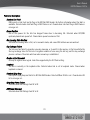
3-3-5 ONU Traffic Management
3-3-5-1 Rules Setting
Function description:
The Rules Setting shows ONU traffic information that includes rule Priority, Action, Parameters, Field Select, Op,
Value. You can control the user data flow by setting the rules. Classification is the process of deciding which
frames are forwarded to particular queues and passed through the ONU. Filtering is the process of deciding which
frames should be dropped, and not passed through the ONU. An ONU has a Queue Configuration, which describes
the number and sizes of queues in use, as well as their connectivity to user ports and EPON logical links. An ONU
also has a classification scheme, which is a set of rules describing how traffic is forwarded to priority queues in
either direction, and possibly a set of filtering rules to control access to the PON.
The concept about Rule Setting is attached on Appendix A Chapter 1.
The above picture shows three entities:
1.
2.
3.
data forwarded to port 1 and queue index 0 when Link Index is equal to 0
data forwarded to port 2 and queue index 0 when Link Index is equal to 1
data forwarded to port 1 and queue index 1 when Link Index is equal to 2
71
The value in Port combobox is EPON-0. It reveals the information that source port is Epon port. It represents
downstream. If the Port combobox is User-1 or User-2, It reveals the information that source port is UNI port. It
represents upstream. In ONU, the port 0 is represent as Epon port, and the port 1,2 is represented as UNI port. In
OLT, the port 0 is represent also as Epon port, and the port 1 is represented as CNI port. You may set frame
destination and forward frames, to form classification rules. You may also discard selected frames, as filter rules.
if you click Add button, ONU Rules Add Information is displayed below.
The clause can be added by clicking Add Clause button. The maximum clause number is eight for single rule. By
clicking Add Clause button, you can add a clause. You can delete a clause by selecting a item and click Del Clause
button.
Parameter description:
Action
The rule action is the action(s) taken upon the frame if all clauses of the rule are true. For example, rules
might set the destination queue for a frame, might add a VLAN tag, or might discard the frame.
72
User’s Manual
GEPON Chassis FK-C16
Precedence
The implemented precedence values for the TK3713 range from 0..15. Lower numbers represent higher
precedence rules; 0 is the highest precedence possible.
Action Parameter
Some actions have additional parameters, as noted below. Rules with other actions should set this field to
zero.
1. Action = Set DestinationSize Description
Parameter 1 = EPON Link index (upstream) 0..n-1 or UNI Port (downstream) 1..n
Parameter 2 = Queue (relative to link/port) 0..n-1
2. Action = Set VIDSize Description
Parameter 1 = VID (bits 11:0)
3. Action = Set COS
Parameter 1= COS (bits 2:0)
Field Select
Field selectors describe fields in Ethernet frames that can be matched in rules.
Op (operator)
value
symbol
description
0
F
Never match
1
==
Field Equal to value
2
!=
Field Not equal to value
3
<=
Field Less than or equal to value
4
>=
Field Greater than or equal to value
5
exists
True if field exists (value ignored)
6
!exist
True if field does not exist (value ignored)
7
T
Always match
Value Type
73
It includes 3 types. Hex, Decimal and IP format. When field is IPv4 DA or IPv4 SA , you must select IP
format type. When field is L2 Dest Addr, you must select Hex type. Whne field is Eth VID, you must select
Decimal type.
Value
Value describe look-up value in Ethernet frames that can be matched in rules.
If you set up the rule and click Apply button, the result is shown below.
You add a rule that forward port 1 queue 0 when Dest Addrress equal 0x001122334455.
If port 1 has 2 queues, the queue index is 0 and 1. If port 0 has 4 queues, the queue index is 0,1,2 and 3. Set up
queue number and queue size, please refer to Queue Config.
If you set up a rule and wouldn’t like to apply, you may click cancel button and give up the rule.
74
User’s Manual
GEPON Chassis FK-C16
3-3-5-2 Queue Configuration
Function description:
This command configures the upstream and downstream queues on the ONU. The upstream queues hold frames
destined for the Logical Links, the downstream queues for the UNI Ethernet ports. Queue sizes are specified in the
order of queue priority, where the first queue has the highest priority. Note that the Queue Configuration command
causes any existing Classification rules on the ONU to be invalidated. Therefore a Queue configuration change
should always be followed by Classification commands to re-install the required classification rules. Filtering
rules on the ONU remain in place.
The message above consists of two configuration sections: upstream and downstream. Links are configured in the
upstream section of the message, where each link can be assigned one or more queues. The downstream section
specifies port configuration, where each port can be assigned one or more queues.
The above picture display three LLID.
Link Index 0 has one queue and queue size is 16*4k .
Link Index 1 has also one queue and queue size is 16*4k.
Link Index 2 has one queue and queue size is 12*4k.
The three Link Index represent upstream.
75
Port 1 has two queues and queue size is 12*4k and 10*4k.
Port 2 has one queue and queue size is 22*4k.
The two ports represent downstream. If you click on “Create New” button, you create one new LLID. The port can’t
be created new on Port Index table. The maximum port in the 3713 ONU is two.
If you click on “Create New” button, Link Index 3 Queue Configuration will be displayed below.
Link Index 3 is set 3 queue.
Queue 0 size is 2*4k.
Queue 1 is 4*4k.
Queue 2 is 5*4k.
If you changed setting as the above picture then click “Apply” button. The result is shown on next page.
76
User’s Manual
GEPON Chassis FK-C16
If you click Link 3 item. The result is shown below. The Link 3 item is selected.
Then you can click Edit button and enter into Editing Queue Configuration, or click Delete button and delete Link 3
item.
77
3-3-5-3 Field Select
Function description:
This command sets the fields parsed from each frame which are used in lookup engine rules to filter or classify
frames. Each port on the ONU has a lookup engine (LUE) that processes frames received on that port. Each lookup
engine has a number of field selectors supported in the hardware. Each field is programmed with a field code that
describes the field parsed from the frame in terms of protocol layer, dword in the frame, bit start, and bit width.
The current programming of each field is described. The Reference Count indicates the number of clauses in rules
that are currently using this field. If the field is currently unused, the reference count will be zero, and the layer
select, dword offset, bit offset, and bit width will contain the maximum possible values for that field on that ONU.
Fields with a non-zero reference count can not be reprogrammed with the Set message. All rules using a given
field must be deleted before the meaning of that field is changed. Note that hardware and firmware system rules
will also use fields in the LUE. These rules cannot be deleted, and so it is possible that some reference counts
will never go to zero.The detail about Field Select is attached on Appendix A Chapter 1.
Click Index 3 item and picture below Apply button will be displayed.
If you click Index 5 item, the picture is shown below.
78
User’s Manual
GEPON Chassis FK-C16
Index 3 item RefCount is not zero. It is not editable. Index 5 item RedCount is zero and so it is editable. You can
change Index 5 Field Name. If you select L2 Preamble in Name field, BitOffset and FieldWidth is changed as Name
field change. You may also select VLAN/L2-Frame or other in LayerSel field. First you select LayerSel value in
LayerSel field and then select Name calue in Name field. BitOffset and FieldWidth is changed as Name field
change finally.
If your selection is finished, click Apply button. The new field is added to system.
The result is shown below.
79
3-3-6 ONU IGMP Snooping
This session describe how to configure IGMP snooping and some IGMP VLAN setting. The detail about ONU IGMP is
attached on Appendix A Chapter 5.
3-3-6-1 IGMP Snooping Parameters
This command is general IGMP Snooping configuration, which has four parameters Robustness Count, Last
Member Query, Number of IGMP Groups (for port 1 and port 2), and Queue for Classification (for port 1 and port 2).
The ONU does not need to be explicitly provisioned, because the ONU obtains many values by snooping. The Query
maximum response times are snooped from the query messages generated by the OLT. The ONU measures the
interval between snooped General Queries to detect the General Query Interval of network Query.
80
User’s Manual
GEPON Chassis FK-C16
Parameter description:
Robustness Count
The Robustness Count is the number of IGMP General Queries. The query may pass with no corresponding
IGMP Report reply before a Groups is removed. So if Robustness Count is set 0, the group will be removed
when it does not get any respond.
Range: 0~12
Default: 2
Last Member Query
If the Group exists, the Last Member Query represents the number of IGMP Group Specific Queries that may
pass with no corresponding IGMP Report reply.
Range: 0~12
Default: 2
Number Of IGMP Groups
This parameter is set per port. The number of IGMP Groups means how many Groups can add in this port.
If the number of IGMP Groups is set 0, that means disabled IGMP snooping, and all IGMP requests will be
sent.
Range: 0~90 (0:disable)
Default: 0
Queue For Classification
This parameter can decide how many Queue used for classification of downstream IP multicast traffic.
Range: 0~6 (0:disable)
Default: 0
81
3-3-6-2 IGMP VLAN (IGMP VLAN Provisioning)
This command can set Tag for the IPMC Frame. There are sixteen groups can be set. If the number of IGMP
VLANs is in unmanaged Group, the frame will be Discard or Ignored. The “Discard” means blocking all IPMC and
IGMP. The “Ignored” means forwarded data and unchanged. The ONU does not support VID translation, and the
VID must be identical for VLAN.
82
User’s Manual
GEPON Chassis FK-C16
Parameter description:
Action for Unmanaged Groups
This parameter has two choices, Discard (block IPMC, IGMP) and Ignore (forward unchanged).
EPON VID
IPMC will be sent to OLT, the frame uses EPON VID.
Range: 0~4096
User VID
The User VID is VID of IPMC, it get from ONU user port.
Range: 0~4096
Max Allowed Groups
This parameter limits IGMP VLAN groups. The Max Allowed Groups is the maximum groups can be joined in
each VLAN by this ONU. If the Max Allowed Groups is setting 0, the ONU will not join any groups, and will
discard all IGMP frames on this VLAN.
Range: 0~255
Default: 0
83
3-3-6-3 IGMP Group Joined
This command will show the entries in the IGMP group table. It will list the number of port and Group IP.
84
User’s Manual
GEPON Chassis FK-C16
3-3-7 ONU Bridging Configuration
3-3-7-1 Bridging Config
This command sets MAC address learning mode of the ports on the ONU. If it is time out, the entries would be
automatically removed from the table.
There are two kinds of Learning Modes, Forward (802.1d Learning) and Drop Until Learned (MAC Access Control).
Forward mode forward unlearned address, which is the default behavior. Drop Until Learned means the port
learns by the allowed learning entry limit, and if the frames are discarded, the MAC address will not be learned.
Parameter description:
Age Limit
An Age Limit of 0 disables aging.
Range: 0~32768 (Unit: 8.75ms) (0: disable)
Default: 8192
85
Entry Limit
An Automatic Learning Entry Limit of zero disables address learning.
Range: 0~64
Default: 64
Learning Mode
It has two modes, Forward (802.1d Learning) and Drop Until Learned (MAC Access Control). Forward
(802.1d Learning) is default mode.
3-3-7-2 IGMP VLAN Options
This command is for IGMP VLAN Ether Type options. It can set Ether Type for TAG under IGMP VLAN.
Parameter description:
VLAN Ether Type
VLAN Ether Type uses hexadecimal.
Tag UP
This parameter can set Enable or Disable.
Tag Down
This parameter can set Enable or Disable.
86
User’s Manual
GEPON Chassis FK-C16
3-3-7-3 ONU Dynamic Table
Function description:
Display the automatically learned MAC addresses for the selected ONU.
Clear Button can be used to clear the dynamic MAC entries for the selected port.
87
3-3-7-4 ONU Broadcast Queue
Function description:
This selects the broadcast/multicast queue to be used in the downstream direction. A different
broadcast/multicast queue may be selected per port. If the queue assigned for broadcast handling is greater than
the number of queues actually configured for that port,ONU will disable its rules that forward broadcast/multicast
traffic.
Parameter description:
port
An Automatic Learning Entry Limit of zero disables address learning.
Range: 1~2
Queue Idx
The broadcast/multicast queue index to be specified for a given port.
Range: 0~255
Default: 0
88
User’s Manual
GEPON Chassis FK-C16
3-3-8 ONU Misc Operations
Function description:
Parameter description:
Enable ONU
Enable ONU to pass user traffic
Disable ONU
Causes the ONU to disable all user data traffic, leaving only the OAM exchange intact.
Reset ONU
Reboot ONU
Restore ONU
Erase all provisioning records of Non-Volatile Store (NVS) and reboot the ONU. This operation returns the
operator provisioning database(e.g. ONU Traffic Management-Rule Setting) to default values. NVS is an
area of flash memory inside the ONU to keep user provisioning data. It include ONU Traffic
Management(Field Select, Queue Config, Rules Setting), ONU IGMP Snooping Parameters, ONU Bridging
Config.
Config
Export ONU Config File -The provisioning database of the ONU can be exported out as a computer file.
Import ONU config File -This file can be used when provisioning database recovery or replication is needed.
89
RF Module
RF Module can be enabled/ disabled. The command is delivered to RF Module by way of ONU. When the
ONU with RF function is operated, ONU Misc Operations have RF Module item.
90
User’s Manual
GEPON Chassis FK-C16
3-3-9 Loopback Test
Function description:
This is an integrated OAM loopback test procedure. It commands the OLT to perform a connectivity and link
quality test on a logical link. The test involves the following steps:
(1) The OLT asks the ONU to put either a link or a UNI port (MAC or PHY) in loopback.
(2) The OLT sends special frames downstream which will be looped back upstream by the target ONU.
(3) After the requested number of frames have been transmitted and received, the OLT commands the ONU to get
out from OAM Loopback mode. The target logical link rusumes user traffic service.
(4) Loopback is finished, and the result would be reported.
A logical link loopback does not affect other logical links on the same physical ONU.
91
Parameter description:
Entity
To specify the end point on the ONU in a loopback test. Possible Values are [Port] or [Logical Link].
LLID
The Mac Address of the target logical link or Mac Address of a logical link which is connected to the target
entity.
Port
If the loopback entity is [Port], the target UNI port should be specified.
Location
If the loopback entity is [Port],the target location( [Mac] or [Phy] )should be specified.
Number of Frames
Number of frames to transmit in a loopback test.
Payload Size(Bytes)
The size of the data portion of an Ethernet frame.
VLAN TAG
Specifies the VID of the loopback frames if frame tagging is wished.1-4094 are valid values for tagged
frame loopback. 0 disable frame tagging.
Test Result
Includes [Frames sent], [Frames received OK], [Corrupted frames received], [Minimum Delay (μs)],
[Maximum Delay (μs)], [Average Delay (μs)].
A frame is presumed lost if it has not returned after 1second. Delay stats are accumulated only for frames
received OK. Five consecutively lost frames will cause the test to be aborted.
92
User’s Manual
GEPON Chassis FK-C16
3-3-10 ONU Provision Wizard
Function description:
The section discribes ONU Provision Wizard. It first display ONU list in the OLT. You click ONU item and then ONU
Queue Configuration will be displayed. You first select “Link number” option and then select Profile option. Profile
option include “Each Llid 1Queue” , “Each Llid 2Queue” and “Load current config”. Upstream and Downstream
queue config is set correctly, you click NEXT. ONU Provision Setting will be displayed. You can roughly set Bridge
Mode , SLA, Multi. SLA and click NEXT. Bridge Mode Setting will be displayed. In the page you can set precisely. If
you set OK, you can click NEXT. Logical Link SLA will be displayed. If you go to final page, ONU Provision Setting
including “Execute The Provision” , “Save Profile” and “Execute The Provision & Save Profile” will be displayed.
Select which option and Click Finish, the procedure will be ended and the action will be done. If you don’t want
the setting, click ABANDON.
Parameter description:
Load Profile
Go to ONU Load Profile. Select file and Load file contents.
PREVIOUS
Go to previous setting.
NEXT
Go to next setting.
QUIT
Quit the ONU Provision.
ABANDON
Abandon the setting.
FINISH
Execute the option. Execute The Provision or Save Profile or Execute The Provision and Save Profile.
93
3-4 Logical Link
3-4-1 Logical Link List
Function description:
The “Logical Link ” table displays all provisioned logical links belonging to an ONU. Click on a row in this table,
the corresponded management function submenu of the selected logical link will show up.
Parameter description:
Link Index
Sequential numbering from 1 to N ( N <= 8 ).
Link Label
The globally unique Mac Address assigned to a logical link. The Mac Address is used within an EPON
system to identify the logical link.
In IEEE802.3ah specification,one ONU supports one logical link.But our ONU support multiple logical
links(up to 8) in a single physical device.
Eight successive Mac Addresses are assigned for one ONU.
Status
Possible values are [Registered] or [Blocked].
Bridging Mode
The provisioned bridging mode of a logical link.
Priority Level
The priority level of the upstream SLA of a logical link.
94
User’s Manual
GEPON Chassis FK-C16
3-4-2 SLA ( Service Level Agreement )
The Downstream traffic means the data from OLT to ONU Links. The Upstream traffic means the data from ONU
Link to OLT. An SLA is disabled, the bandwidth of Logical Link will be not granted, and the multicast traffic will
not be passed to the link. If the link is in any kind of Shared VLAN mode, the SLA (upstream and downstream)
must be enabled.
About the bandwidth, the Maximum Allowed Bandwidth (Max Bw) must be more than Minimum Guaranteed
Bandwidth (Min Bw), the difference must be 256Kbps or greater.
The Logical Link with one of the three priority levels for scheduling purposes. The three priorities are 0(high),
1(medium), 2(low). The priority is decided in SLA parameters, mode, Maximum Allowed Bandwidth, and Minimum
Guaranteed Bandwidth, the configuration with the following SLA Parameters.
The detail about SLA is attached on Appendix A Chapter 5.
DBA Token, Scheduler Max Token, Scheduler Min Token, and Force Report provide a low-level control, which is
used in queue schedulers. The link and queue schedulers use a weighted priority based round-robin discipline.
95
They set upstream and downstream weights on a link. It is recommended that the parameters use the default
settings as long as possible. If the Force Report is YES, it means each grant from OLT forces a report from ONU,
Down stream has no such setting. The default value of the Force Report is YES. After the ONU is authorized, SLA
enable/disable can be changed.
Parameter description:
Maximum Allowed Bandwidth (Max Bw)
The maximum allowed use Bandwidth, when the traffic is not crowded.
Range: 1000~1000000 (Unit: Kbps)
Default: 100000
Minimum Guaranteed Bandwidth (Min Bw)
This parameter will guarantee minimum bandwidth, when the data need to transmit, no matter what the
traffic is crowded or not.
Range: 0~1000000 (Unit: Kbps)
Default: 100000
Max Burst
Range: 1~255 (Unit: KBytes)
Default: 100
DBA Token
Range: 0~255 (Unit: KBytes)
Default: 4
Scheduler Max token
Range: 0~511 (Unit: KBytes)
Default: 2
96
User’s Manual
GEPON Chassis FK-C16
Scheduler Min Token
Range: 0~511 (Unit: KBytes)
Default: 2
Force Report
It has two modes, YES and NO. “YES” is default value.
3-4-3 Multicast SLA
This command allows bandwidth control on multicast link for Shared VLAN. The aggregate shaper must be
disabled, before setting the multicast SLA. If the aggregate shaper must be used, it must be enabled after setting
multicast SLA. If Mode is sensitive, the Maximum Allowed Bandwidth must be equal to Minimum Guaranteed
Bandwidth.
97
Parameter description:
Maximum Allowed Bandwidth (Max Bw)
Range: 256~1000000 (Unit: Kbps)
Default: 1000000
Minimum Guaranteed Bandwidth (Min Bw)
Range: 0~1000000 (Unit: Kbps)
Default: 1000000
Max Burst
Range: 1~256 (Unit: KBytes)
Default: 100
Mode
It has two modes, Tolerant and Sensitive.
Note: The Multicast SLA can be enabled in Shared VLAN, Priority Remapping Shared VLAN, Priority Shared VLAN, and Trans.
Pri. Shared VLAN, Double Tagged Shared VLAN mode.
98
User’s Manual
GEPON Chassis FK-C16
3-4-4 Bridge Mode Setting
Function description:
This command sets the per-Logical Link forwarding mode and learning table entry limit. Logical links may be
configured for simple 802.1d bridging or for various flavors of VLAN bridging.
The OLT maintains a single MAC table that may contain up to 4095 dynamically learned MAC addressees used for
downstream bridging and other features. For bridging modes that use the MAC table, the OLT learns the SA of
upstream frame on a per LLID basis. An upper limit on the number of table entries that may be used is maintained
for each LLID. When the sum of dynamically learned addresses reaches the per-LLID limit, additional MAC
addresses will not be learned even if there is room in the table. The aggregate size of all per LLID MAC tables may
exceed the available hardware table size (4095). In such a configuration, if the entire learning table is full, the
oldest entry from all per LLID tables will be the target for replacement.
In the event that a per-LLID learning table becomes full, an attempt to learn another MAC address on that LLID
will trigger a MAC Table Overflow alarm to be issued to the host processor. In such a case the oldest entry in that
table is subject to replacement by the SA of a frame received upstream (that is frames received by the EPON port).
Bridging modes that require a VLAN tag will not forward traffic until at least one VID has been set.
If a conflict exists between LLIDs configured in different bridging modes (DA matches simple bridged, but VLAN
tag matches an LLID configured in a VLAN mode) the packet will be dropped.
The detail about Bridge Mode is attached on Appendix A Chapter 2.
99
Parameter description:
Bridge Mode
Decide data flow by way of setting various Bridging Type.
Bridging Type include 15 types.
0 = Simple Bridged,
1 = Dedicated Single VLAN,
2 = Dedicated Double VLAN,
3 = Shared VLAN,
4 = Transparent VLAN,
7 = Prioritized VLAN,
8 = Priority Remapping Single VLAN,
9 = Priority Remapping Double VLAN,
10 = Priority Remapping Shared VLAN,
11 = Priority Shared VLAN,
13 = Transparent Priority Shared VLAN
14 = Transparent Shared VLAN with Broadcast
15 = Double Tagged Shared VLAN
Entry Limit
An upper limit on the number of table entries that may be used is maintained for each LLID.
Range: 0~4095
Default: 64
100
User’s Manual
GEPON Chassis FK-C16
3-4-4-1 Vlan Tag Setting
Function description:
This function associates a VLAN tag with a logical link when the link is configured for one of the VLAN bridging
types. It is possible for some bridging modes to associate a VLAN tag with multiple logical links by repeating this
command with different logical links. For example, a Shared VLAN could be created bridging a number of logical
links. Conversely, a logical link may be assigned multiple VLAN tags. For example, the Transparent VLAN mode
allows multiple VLAN tags per logical link.
When provisioning tags, two fields are included in the message: VLAN Tag, and Translated VLAN ID. However, the
field labeled “Translated VLAN ID” is only meaningful when the corresponding LLID is configured to use
Translated VLAN Mode(FK-C16 not supported Translated Vlan Mode). For all other modes there is no Translated
VLAN Mode.
COS: The VLAN Id field is 16 bits out of which the Most significant 3 bits denote the COS value.
If Bridge mode is Simple Bridge, can’t set vlan tag. If Bridge mode is Dedicated Single VLAN, Dedicated Double
VLAN, Shared VLAN, Transparent VLAN, Priority Remapping Single VLAN, Priority Remapping Double VLAN, Priority
Remapping Shared VLAN, Transparent Shared VLAN with Broadcast, you only set Vlan and Upstream Cos.
If Bridge mode is Prioritized VLAN, Priority Shared VLAN, Transparent Priority Shared VLAN, you set Vlan, Upstream
Cos, Max Cos, Min Cos and Using Cos.
The above picture shows to set vlan tag in shared vlan mode.
101
The above picture shows to set vlan tag in prioritized vlan mode.
102
User’s Manual
GEPON Chassis FK-C16
3-4-5 EPON Security
This command is used in encryption keys. This parameter is a timeout value. When timer expires, a new key will
be generated and exchanged. That setting 0 means disable security. The detail about encryption key is attached
on Appendix A Chapter 3.
Key Exchange Timer
Range: 0~65535 (Unit: sec)
Default: 0 (Disable: 0)
103
3-4-6 Link Statistics
Function description:
Request statistics is related to the individual Logical Link specified. It includes OLT side and ONU side. The
directions include upstream and downstream. If you click Refresh button, the statistics information will be
displayed. If you click Clear button, the statistics information will be cleared. Upstream direction reflects the
traffic from Epon port to CNI port. Downstream direction reflects the traffic from CNI port to Epon port.
104
User’s Manual
GEPON Chassis FK-C16
3-4-7 Link Operation
Function description:
Parameter description:
Block
Deregisters a logical link and prevent it from registering to its OLT.
Unblock
Makes a logical link being participable in OLT’s normal discovery process.
Rediscover
Deregisters a logical link to force an ONU to re-register this logical link.
Restore
Erases only provisioning records about a logical link kept in the NVS of an OLT.This operation returns the
operator provisioning records which are related with a logical link to default values.
105
3-5 System
3-5-1 System Information
Display the basic information of FK-C16
106
User’s Manual
GEPON Chassis FK-C16
Parameter description:
Model Name
The model name of this device.
System Description
As it is, this tells what this device is. Here, it is “Managed Chassis”.
Location
Basically, it is the location where this converter chassis is put. User-defined.
Contact
For easily managing and maintaining device, you may write down the contact person and phone here for
getting help soon. You can configure this parameter through the device’s user interface or SNMP.
Device Name
The name of the converter chassis. User-defined. Default is FK-C16.
CID-RID (Rack ID – Chassis ID)
Rack ID(RID) indicates which rack the machine is located.
Chassis ID(CID) indicates which chassis of a rack the machine is located.
System Up Time
The time accumulated since this converter chassis is powered up. Its format is day, hour, minute, second.
Current Time
Show the system time of FK-C16. Its format: day of week, month, day, hours : minutes : seconds, year. For
instance, Wed, Feb. 23, 12:10:10, 2005.
BIOS Version
The version of the BIOS of this converter chassis.
Firmware Version
The firmware version of this converter chassis.
CPU HW-Mech Version
The version of CPU Hardware and Mechanical. The figure before the hyphen is the version of electronic
hardware; after the hyphen is the version of mechanical.
107
CPU Code Number
The serial number is assigned by the manufacturer.
Chassis HW-Mech Version
The version of Chassis Hardware and Mechanical. The figure before the hyphen is the version of electronic
hardware; after the hyphen is the version of mechanical.
Chassis Code Number
The Code Number is a manufacturer code assigned by the manufacturer.
Host IP Address
It is the Ethernet MAC address of the agent management interface in this converter chassis.
Host MAC Address
The IP address is that indicates where FK-C16’s management interface is located (e.g. default IP address
of FK-C16 is 192.168.1.1). The management interface is physical linked on CPU board’s Ethernet port 1 and
port 2.
Device Port
Show all types and numbers of the port in FK-C16.
RAM Size
The size of the DRAM in this converter chassis.
Flash Size
The size of the flash memory in this converter chassis.
System Temperature
The air temperature inside of this converter chassis.
Fan
Display the RPM of the fans for cooling.
Voltage
Show the figure of the DC voltage from power source in this converter chassis.
108
User’s Manual
GEPON Chassis FK-C16
3-5-2 IP Configuration
FK-C16
Set up IP Address, Subnet Mask, Gateway and DNS.
Parameter description:
DHCP Setting
DHCP is the abbreviation of Dynamic Host Configuration Protocol. Here DHCP means a switch to turn ON or
OFF the function.
The converter chassis supports DHCP client used to get an IP address automatically if you set this function
“Enable”. When enabled, the converter chassis will issue the request to the DHCP server resided in the
network to get an IP address. If DHCP server is down or does not exist, the converter chassis will issue the
request and show IP address is under requesting, until the DHCP server is up. Before getting an IP address
from DHCP server, the device will not continue booting procedures. If set this field “Disable”, you’ll have to
input IP address manually.
Default: Disable
109
IP Address
Users can configure the IP settings and fill in new values if users set the DHCP function “Disable”. Then,
click <Apply> button to update.
When DHCP is disabled, Default: 192.168.1.1
If DHCP is enabled, this field is filled by DHCP server and will not allow user manually set it any more.
Subnet Mask
Subnet mask is made for the purpose to get more network address because any IP device in a network
must own its IP address, composed of Network address and Host address, otherwise can’t communicate
with other devices each other. But unfortunately, the network classes A, B, and C are all too large to fit for
almost all networks, hence, subnet mask is introduced to solve this problem. Subnet mask uses some bits
from host address and makes an IP address looked Network address, Subnet mask number and host
address. It is shown in the following figure. This reduces the total IP number of a network able to support,
by the amount of 2 power of the bit number of subnet number (2^(bit number of subnet number)).
32 bits
Network ID
Host ID
Network ID
Host ID
Subnet number
Subnet mask is used to set the subnet mask value, which should be the same value as that of the other
devices resided in the same network it attaches.
Default: 255.255.255.0
110
User’s Manual
GEPON Chassis FK-C16
Default Gateway
Set an IP address for a gateway to handle those packets that do not meet the routing rules predefined in
the device. If a packet does not meet the criteria for other pre-defined path, it must be forwarded to a
default router on a default path. This means any packet with undefined IP address in the routing table will
be sent to this device unconditionally.
Default: 192.168.1.254
DNS
It is Domain Name Server used to serve the translation between IP address and name address.
The converter chassis supports DNS client function to re-route the mnemonic name address to DNS server
to get its associated IP address for accessing Internet. User can specify a DNS IP address for the converter
chassis. With this, the converter chassis can translate a mnemonic name address into an IP address.
There are two ways to specify the IP address of DNS. One is fixed mode, which manually specifies its IP
address, the other is dynamic mode, which is assigned by DHCP server while DHCP is enabled. DNS can
help you easily remember the mnemonic address name with the meaningful words in it. Default is no
assignment of DNS address.
Default: 0.0.0.0
Current IP:
Display the IP address that is used by the device currently.
111
3-5-3 System Time Configuration
Set up the system time by manual input.
FK-C16
NTP is Network Time Protocol and is used to sync the
network time based on Greenwich Mean Time (GMT).
Note: The function also supports daylight saving for different area’s time adjustment.
112
User’s Manual
GEPON Chassis FK-C16
Parameter description:
Manual
This is the function to adjust the time manually. Filling the valid figures in the fields of Year, Month, Day,
Hour, Minute and Second respectively and press <Apply> button, time is adjusted. The valid figures for the
parameter Year, Month, Day, Hour, Minute and Second are >=2000, 1-12, 1-31, 0-23, 0-59 and 0-59
respectively. Input the wrong figure and press <Apply> button, the device will reject the time adjustment
request. There is no time zone setting in Manual mode.
Default: Year = 2000, Month = 1,
Hour = 0,
Day = 1
Minute = 0, Second = 0
NTP
NTP is Network Time Protocol and is used to sync the network time based Greenwich Mean Time (GMT). If
use the NTP mode and select a built-in NTP time server or manually specify an user-defined NTP server as
well as Time Zone, the converter chassis will sync the time in a short after pressing <Apply> button.
Though it synchronizes the time automatically, NTP does not update the time periodically without user’s
processing.
Time Zone is an offset time off GMT. You have to select the time zone first and then perform time sync via
NTP because the converter chassis will combine this time zone offset and updated NTP time to come out
the local time, otherwise, you will not able to get the correct time. The converter chassis supports
configurable time zone from –12 to +13 step 1 hour.
Default Time zone: +8 Hrs.
Daylight Saving
Daylight saving is adopted in some countries. If set, it will adjust the time lag or in advance in unit of
hours, according to the starting date and the ending date. For example, if you set the day light saving to be
1 hour. When the time passes over the starting time, the system time will be increased one hour after one
minute at the time since it passed over. And when the time passes over the ending time, the system time
will be decreased one hour after one minute at the time since it passed over.
The converter chassis supports valid configurable day light saving time is –5 ~ +5 step one hour. The zero
for this parameter means it need not have to adjust current time, equivalent to in-act daylight saving. You
don’t have to set the starting/ending date as well. If you set daylight saving to be non-zero, you have to set
the starting/ending date as well; otherwise, the daylight saving function will not be activated.
Default for Daylight Saving: 0.
113
Day Light Saving Start
This is used to set when to start performing the day light saving time.
Mth:
Range is 1 ~ 12.
Default: 1
Day:
Range is 1 ~ 31.
Default: 1
Hour:
Range is 0 ~ 23.
Default: 0
Day Light Saving End
This is used to set when to stop performing the daylight saving time.
Mth:
Range is 1 ~ 12.
Default: 1
Day:
Range is 1 ~ 31.
Default: 1
Hour:
Range is 0 ~ 23.
Default: 0
114
User’s Manual
GEPON Chassis FK-C16
3-5-4 Account Configuration
In this function, only the administrator can create, modify or delete the username and password. The
administrator can modify other guest identities’ and administrator-equivalent identities’ passwords. A user with
Guest-equivalent identity cannot modify his password.
FK-C16
Create a new account
Note:
Please confirm the user’s Manager/Guest identity on the list of Identity in advance before configuring the username and
password.
Account number is added to 30. Only admin login can create/modify/delete user, and other administrator can see only .
The differences admin and other administrator are 1.create/delete user , 2.Clear Log/Epon Log.
115
3-6 SNMP Configuration
FK-C16
Set up SNMP status, community name, and up
to 6 Host IP address that SNMP Trap assigned.
Parameter description:
SNMP
The term SNMP here is used for the activation or de-activation of SNMP. Default is Enable.
Get/Set/Trap Community
Community name is used as password for authenticating if the requesting network management unit
belongs to the same community group. If they both don’t have the same community name, they don’t
belong to the same group. Hence, the requesting network management unit can not access the device with
different community name via SNMP protocol; if they both have the same community name, they can talk
each other.
Community name is user-definable with a maximum length of 15 characters and is case sensitive. There is
not allowed to put any blank in the community name string. Any printable character is allowable.
116
User’s Manual
GEPON Chassis FK-C16
The community name for each function works independently. Each function has its own community name.
Say, the community name for GET only works for GET function and can’t be applied to other function such
as SET and Trap.
Default community name for GET: public
Default community name for SET: private
Default Set function: Enable
Default community name for Trap: public
Default trap host IP address: 0.0.0.0
Default trap port: 162
Trap Host
In the converter chassis, there are 6 trap hosts supported. Each of them has its own community name and
IP address; is user-definable. To set up a trap host means to create a trap manager by assigning an IP
address to host the trap message. In other words, the trap host is a network management unit with SNMP
manager receiving the trap message from the managed converter chassis with SNMP agent issuing the trap
message. 6 trap hosts can prevent the important trap message from losing.
For each public trap, the converter chassis supports the trap event Cold Start, Warm Start, Link Down, Link
Up and Authentication Failure Trap. They can be enabled or disabled individually. When enabled, the
corresponded trap will actively send a trap message to the trap host when a trap happens. If all public
traps are disabled, no public trap message will be sent. As to the Enterprise (no. 6) trap is classified as
private trap, which are listed in the Trap Alarm Configuration function folder.
Default for all public traps: Enable.
117
3-7 Alarm
3-7-1 Events Configuration
FK-C16
The trap events that had been checked will be sent out in three ways, including e-mail, SMS and Trap.
Parameter description:
Trap
Cold Start
Warm Start
Link Down
Link Up
Authentication Failure
Login
User Login
User Logout
VDC
118
User’s Manual
GEPON Chassis FK-C16
VDC Normal
VDC Over/Under
FAN
FAN Normal
FAN Abnormal
Power
Power Inserted
Power Abnormal
Power Removed
Temperature
Temperature Normal
Temperature Abnormal
Module
Module Egress Rated BW changed
Module Ingress Rated BW changed,
Module Inserted
Module Removed
Remote
Remote Fiber Link up
Remote Fiber Link down
Remote TP Link Up
Remote TP Link down
119
Event
Cold Start
Warm Start
Authentication Failure
User Login
User Logout
Temperature Normal
Temperatue Abnormal
Voltage Normal
Voltage Abnormal
Fan RPM Normal
Fan RPM Abnormal
Power Inserted
Power Removed
Power Normal
Power Abnormal
OLT Insert
OLT Remove
CNI Link Down
CNI Link Up
Standard Link Fault
Epon Link Up
Epon Link Down
Queue Overflow
MAC Learing Table Overflow
Key Exchange Failure
Number Of Links Exceeded
Jumbo Frame Error
EPON No Links Discovery
OLT Bad
UNI Link Up
UNI Link Down
Loopback
Standard Dying Gasp
Dying Gasp Power Failure
ONU Power Abnormal
Come from
Host
Host
Host
Host
Host
Host
Host
Host
Host
Host
Host
Host
Host
Host
Host
OLT
OLT
OLT
OLT
OLT/ONU
OLT/ONU
OLT/ONU
OLT/ONU
OLT/ONU
OLT/ONU
OLT
OLT
OLT
OLT
ONU
ONU
ONU
ONU
ONU
ONU
120
User’s Manual
GEPON Chassis FK-C16
Parameter description:
Standard Link Fault
ONU reports a Link Fault via the flag in the 802.3ah OAM header. No further information about the fault is
available. Detected when Link fault flag in OAM frame is set. Cleared when Link fault flag in OAM frame in
no longer set.
Queue Overflow
One of the queues for the link has dropped frames due to becoming full. Detected when OLT/ONU
upstream,downstream queue full. Cleared when queue becomes not full.
Mac Learning Table Overflow
MAC address learning table is full, not in overwrite mode, and a new MAC address was encountered.
Key Exchange Fallure
The link peer has failed to generate a new key message, or to switch to the new key, in the time allotted by
the key exchange timer for this link. Encryption remains in force using the old key, and the key exchange
process continues. The alarm will clear when a new key is established.
Number of Link Exceeded
Attempt to register more logical links than supported by the OLT flash setting.
Loopback
The link is currently in the loopback state. Detected when link is set to loopback mode. Cleared when
loopback is cleared.
Standard Dying Gasp
ONU reports Dying Gasp via that bit in 802.3ah OAM header. Detected When DG bit is set . Cleared when DG
bit is no longer set .
Dying Gasp Power Failure
Detected when ONU Voltage from 5V to 0V.
ONU Power Abnormal
Detected when ONU Voltage from 5V to 4V.
121
3-7-2 Email Configuration
FK-C16
Fill in Mail Server IP, Username and Password, then, the
happened trap events will be sent to E-mail Address1~ 6.
Parameter description:
Mail Server
The IP address of the server transferring your email.
Username
Your username on the mail server.
Password
Your password on the mail server.
Email Address 1 – 6
E-mail address that would like to receive the alarm message.
122
User’s Manual
GEPON Chassis FK-C16
3-8 Soak Time Configuration
This item sets the Soak times to set and clear an alarm. A condition becomes an alarm only if the condition
remains in effect for a period longer than the Soak time. Similarly, an alarm would be cleared if the clear
condition is longer than the setting in Soak Time Before Clear. The Loop back and the Statistics alarms are not
soaked.
123
3-9 Configuration
3-9-1 Save/Restore
FK-C16
Press above buttons to save or restore configuration
Parameter description:
Save Start
Press <Save Start> button to save the working configuration into the flash. Then, this configuration will be
the one after rebooting the system.
Save User
Press <Save User> button to save current configuration as a user configuration file in flash memory. You
can use <Restore User> button function to restore the backup user configuration.
Restore Default
Press <Restore Default > button to restore factory default setting included default IP address,
Authorization, ONU Subscriber, Others(Epon User Rules, OLT Reboot Time, Config Backup Time).
IP checked represents IP is set 192.168.1.1.
Authorization checked represents clean Authorization parts of Flash.
ONU Subscriber checked represents clean ONU Subscriber parts of Flash.
124
User’s Manual
GEPON Chassis FK-C16
Miscellaneous checked represents clean CLI ONU User Rule and Field Select Template,OLT Reboot
Time,Export Config Backup Setting
Restore User
Press <Restore User> button to restore user configuration, the user configuration file was saved by <Save
User> button function.
3-9-2 Configure Export / Import File Path
FK-C16
User can Export FK-C16’s configuration data to the directory assigned
by TFTP server or import a configure file ( *.cfg) from TFTP server.
Function description:
The entire FK-C16 chassis configuration could be saved into a file. You can use the function "Import Export
Configuration". The new management module all of configurations will be recovered after the following
procedures, except IP address. You have to configure the IP address first, because the recover configuration
mechanism is based on TFTP function so that IP address needs to be ready first.
125
Step 1.
Run “Save Start” configuration function.
Step 2.
Press “Export Start” button to save the entire configuration of a chassis to a file.
Step 3.
Press “Import Start” button to load the saved file and reinstall the complete configuration
of the chassis.
Step 4.
Reboot Host.
Parameter description:
TFTP Server IP
Display the IP address of TFTP server you set up.
Export File Path
Key in the file and path name for exporting configuration file.
Import File Path
Key in the file and path name for importing configuration file.
Export Start
Press <Export Start> button to export the configuration file into TFTP server.
Export User-Conf
Press <Export User-Conf> button to export the user configuration file to TFTP server.
Import Start
Press <Import Start> button to import the configuration file into chassis’s start memory block from TFTP
server.
Import User-Conf
Press <Import User-Conf> button to import the configuration file into chassis’s user memory block from
TFTP server.
126
User’s Manual
GEPON Chassis FK-C16
3-9-3 Host/OLT/ONU Export Config Backup
Function description:
The entire FK-C16 chassis configuration could be saved into a file. You can use the function "Import Export
Configuration". The export config backup time can be scheduled. For example, (1)you export config file at 8 a.m.
every day. Interval Backup is set 1. When to Backup is set 8. (2)If you export config file at 1 p.m. every two days.
Interval Backup is set 2. When to Backup is set 13.
Parameter description:
Interval Backup
Display the backup interval that FK-C16 chassis export Host/OLT/ONU config file.
When to Backup
Display when FK-C16 chassis backup config file.
127
3-10 Diagnostic
3-10-1 Diagnostic
FK-C16
The system can do the self-diagnostic test to detect that
whether EEPROM, UART, DRAM and Flash are normal or not.
3-10-2 Ping Test
FK-C16
Fill in an IP address and press <Ping> button, then, the
system will report the host is alive or dead of the ping result.
128
User’s Manual
GEPON Chassis FK-C16
Parameter description:
IP Address
An IP address with the version of v4, e.g. 192.168.1.1.
Default Gateway
IP address of the default gateway.
Ping Result
You can ping the remote station or converter chassis that connects to the managed port. It will show the
Ping destination IP is alive. Otherwise, it shows destination is dead.
3-11 TFTP Server
FK-C16
Parameter description:
TFTP Server
A TFTP server IP address location path you want to upgrade.
129
3-12 Log Data
FK-C16
Record the time and the name of the trap events that had happened in the order of No.
Parameter description:
TFTP Server
User can upload all data in log to TFTP server if the TFTP is enabled. In the log, it can accommodate
maximum 200 records, which means up to 200 records can be uploaded to TFTP server each time.
No.
Display the order number that the trap happened.
Time
Display the time that the trap happened.
Events
Display the trap event name.
130
User’s Manual
GEPON Chassis FK-C16
Auto Upload
Press <Auto Upload Enable/Disable> button to enable/disable auto upload log data function. The Log Data
maximum entry is 200. If the auto upload be enabled, the log data will be upload to TFTP server
automatically when the data entries was over 200.
Upload Log
Press <Upload Log> button to upload log data function by manual. The Log Data will be upload to TFTP
server when you use mouse to click left on <Upload Log> button.
Clear Log:
All of the log data will be deleted, when you use mouse to click left on <Clear Log> button.
Note:
The trap event log massage of the Web UI and CLI are combined with the FK-C16 firmware, we cannot access and
change the trap event log message from them.
The FK-C16 supports SNMP trap function, the SNMP trap event message is defined in FK-C16 MIB file. The MIB file is a
text file, it can be compiled into the SNMP NMS (for example: HP Open View, Castle Rock SNMPc, MG-Soft MIB
Browser, etc.). The SNMP trap event message would be shown on the NMS trap receiver when the FK-C16 MIB file was
compiled into the NMS and FK-C16 trap event had happened. You can access and change the MIB file for trap event
message modification.
131
3-13 EPON Log File
FK-C16
Record the time and the name of the EPON trap
events that had happened in the order of No.
Parameter description:
TFTP Server
User can upload all data in EPON log to TFTP server if the TFTP is enabled. In the EPON log, it can
accommodate maximum 200 records, which means up to 200 records can be uploaded to TFTP server each
time.
No.
Display the order number that the EPON trap happened.
Time
Display the time that the EPON trap happened.
Events
Display the EPON trap event name.
132
User’s Manual
GEPON Chassis FK-C16
Auto Upload
Press <Auto Upload Enable/Disable> button to enable/disable auto upload EPON log data function. The
EPON Log Data maximum entry is 120. If the auto upload be enabled, the log data will be upload to TFTP
server automatically when the data entries was over 120.
Upload Log
Press <Upload Log> button to upload log data function by manual. The EPON Log Data will be upload to
TFTP server when you use mouse to click left on <Upload Log> button.
Clear Log
All of the EPON log data will be deleted, when you use mouse to click left on <Clear Log> button.
Note:
The EPON trap event log massage of the Web UI and CLI are combined with the FK-C16 firmware, we cannot access and
change the EPON trap event log message from them.
The FK-C16 supports SNMP trap function, the SNMP trap event message is defined in FK-C16 MIB file. The MIB file is a
text file, it can be compiled into the SNMP NMS (for example: HP Open View, Castle Rock SNMPc, MG-Soft MIB
Browser, etc.). The SNMP trap event message would be shown on the NMS trap receiver when the FK-C16 MIB file was
compiled into the NMS and FK-C16 trap event had happened. You can access and change the MIB file for trap event
message modification.
133
3-14 Firmware Upgrade
3-14-1 Host Firmware Upgrade
FK-C16
Fill in TFTP server IP address, and Path and filename. Then,
press <Upgrade> button to upgrade the management board.
Parameter description:
TFTP Server
A TFTP server stored the image file you want to upgrade.
Path and Filename
File path and filename stored the image file you want to upgrade.
Upgrade
Click left on <Upgrade> button to run software upgrade.
134
User’s Manual
GEPON Chassis FK-C16
3-14-2 OLT Upgrade
FK-C16
Fill in TFTP server IP address, and Path and filename. To select slot number and
application, then press <Upgrade> button to upgrade the OLT converter modules firmware.
Parameter description:
TFTP Server
A TFTP server stored the image file you want to upgrade.
Path and Filename
File path and filename stored the image file you want to upgrade.
Slot
To select slot numbers for OLT firmware upgrade.
Upgrade
Click left on <Upgrade> button to run software upgrade.
Reboot
Click left on <Reboot> button to reboot OLT.
135
3-14-3 ONU Upgrade
FK-C16
The ONU devices is under
the OLT at remote CPE
side, so you must select
the slot number to show
the ONU devices under
the slot OLT linked at
remote CPE side.
FK-C16
Fill in TFTP server IP address, Path and filename,and select ONU devices , then
press <Upgrade> button to upgrade the remote CPE side ONU converters firmware.
136
User’s Manual
GEPON Chassis FK-C16
Parameter description:
TFTP Server
A TFTP server stored the image file you want to upgrade.
Path and Filename
File path and filename stored the image file you want to upgrade.
Linked ONU Devices
To select ONU devices for firmware upgrade.
Upgrade
Click left on <Upgrade> button to run software upgrade.
Reboot
Click left on <Reboot> button to reboot ONU.
3-15 Reboot
FK-C16
Press <Save and Reboot> or <Reboot> button to restart FK-C16 Converter Chassis.
Note: Reboot takes the same effect as the RESET button on the front panel of FK-C16. It will take around thirty (30) seconds
to complete the system boot.
137
3-15-1 OLT Reboot Time
Function description:
OLT Reboot Time describe when OLT reboot. You can set Year, Month, Day, Hour, Minute in the future and select
which OLT to reboot. For example Year is 2008,Month 11, Day 12,Hour 13, Minute 14 and Which OLT Reboot is
2,4,6. It represent the 2,4,6 OLT will reboot at 2008/11/12 13:14:xx.
Parameter description:
Reboot Time
Display the time that OLT reboot.
Which OLT Reboot
Display which OLT to reboot.
Clear
Clear setting in the page. After clicking Clear button, you must click Apply button.
138
User’s Manual
GEPON Chassis FK-C16
3-16 Logout
FK-C16
Press <Logout> button to allow you to logout the system and prevent other users from
the system without the permission. And then, you will return to the login screen.
Note: Pull down the <Auto Logout> list at the left-top corner to explicitly ON/OFF this logout function. If no action and no key
is stroke as well in any function screen more than the minutes you set up, FK-C16 will have you logout automatically.
139
Chapter 4 CLI Management
4-1 CLI Management
Refer to Chapter 2 for basic installation. The following description is the brief of the network connection.
1.
2.
3.
4.
Locate the correct DB-9 RS-232 cable with female DB-9 and Ear-Phone jack connector. RS-232 cable comes
with the management chassis. Refer to the Appendix C for RS-232 serial cable specification.
Attach the Ear-Phone jack connector to the female Ear-Phone jack serial port connector on the Management
board.
Attach the other end of the DB-9 cable to an ASCII terminal emulator or PC Com-1, 2 port. For example, PC
runs Microsoft Windows HyperTerminal utility.
At “Com Port Properties” Menu, configure the parameters as below: (see the next section)
Baud rate
57600
Stop bits
1
Data bits
8
Parity
N
Flow control
none
4-1-1 Login
The command-line interface (CLI) is a text-based interface. User can access the CLI through either a direct serial
connection to the device or a Telnet session. The default values of FK-C16 converter chassis are listed below:
Username: admin
Password: admin
After you login successfully, the prompt will be shown as “#“ if you are the first login person; otherwise it may
show “$“. See the following two figures. The former means you behave as an administrator and have the access
right of the system. As to the latter, it means you behave as a guest and are only allowed to view the system
without the permission to do any setting for this Converter Chassis.
140
User’s Manual
GEPON Chassis FK-C16
Furukawa Managed GEPON Chassis
Login: admin
Password:
FK-C16#
Furukawa Managed GEPON Chassis
Login: admin
Password:
FK-C16$
141
4-2 Commands of CLI
To see the commands of the mode, please input “?” after the prompt, then all commands will be listed in the
screen. All commands can be divided into two categories, including Global commands and Local commands.
Global commands can be used wherever the mode you are. They are “end”, “exit”, “history”, “help”, “save start”,
“save user”, “restore default”, “restore user” and “logout”. For more details, please refer to Section 4-2-1.
Command instructions reside in the corresponding modes are local commands. The same command with the
same command name may occur but perform totally different function in different modes. For example, “show” in
IP mode performs displaying the IP information; however, it performs displaying the system information in system
mode. For more details, please refer to Section 4-2-2.
142
User’s Manual
GEPON Chassis FK-C16
4-2-1 Global Commands of CLI
exit
Syntax:
exit
Description:
Back to the previous mode.
When you enter this command, your current position would move back to the previous mode. If you use this
command in the top mode, you are still in the position of the top mode.
Argument:
None.
Possible value:
None.
Example:
FK-C16# system
FK-C16(system)# exit
FK-C16#
end
Syntax:
end
Description:
Back to the top mode.
When you enter this command, your current position would move to the top mode. If you use this command
in the top mode, you are still in the position of the top mode.
Argument:
None.
143
Possible value:
None.
Example:
FK-C16# alarm
FK-C16(alarm)# events
FK-C16(alarm-events)# end
FK-C16#
help
Syntax:
help
Description:
To show available commands.
Some commands are the combination of more than two words. When you enter this command, the CLI
would show the complete commands. Besides, the command would help you classify the commands
between the local commands and the global ones.
Argument:
None.
Possible value:
None.
Example:
FK-C16# ip
FK-C16(ip)# help
144
User’s Manual
GEPON Chassis FK-C16
Commands available:
------------<< Local commands >>-----------account
Enter into account mode
alarm
Enter into alarm mode
autologout
Change autologout time
config-file
Enter into config file mode
diag
Enter into diag mode
epon-log
Enter into epon log mode
firmware
Enter into firmware mode
hostname
Change hostname
ip
Enter into ip mode
link
Enter into Logical Link Management
log
Enter into log mode
olt
Enter into OLT Management
onu
Enter into ONU Management
reboot
Reboot the Host CPU
reboot-module
Reboot Module(OLT)
snmp
Enter into snmp mode
system
Enter into system mode
tftp
Enter into tftp mode
time
Enter into time mode
145
------------<< Global commands >>-----------end
Back to the top mode
exit
Back to the previous mode
help
Show available commands
history
Show a list of previously run commands
logout
Logout the system
restore
Restore default or user config
save
Save as start or user config
oltlinks
Show Both Discovered And Blocked Links Of an OLT
Onuname
Show onu name
Onulinks
Show onu links and bridge mode
param OLT
Hint OLT parameter
param SLOTs
Hint SLOTs parameter
param ONU
Hint ONU parameter
param LINK
Hint LINK parameter
history
Syntax:
history [#]
Description:
To show a list of previously run commands.
When you enter this command, the CLI would show a list of previously run commands which typed before.
The CLI supports the records up to 256 records. If no argument is typed, the CLI would list total records up
to 256. If optional argument is given, the CLI would show the only last number of records, given by the
argument.
Argument:
[#]: show last number of history records. (optional)
146
User’s Manual
GEPON Chassis FK-C16
Possible value:
[#]: 1, 2, 3, …., 256.
Example:
FK-C16(ip)# history
Command history:
0. ?
1. remote
2. exit
3. alarm
4. events
5. end
6. help
7. ip
8. help
9. history
FK-C16(ip)# history 3
Command history:
8. help
9. history
10. history 3
FK-C16(ip)#
147
logout
Syntax:
logout
Description:
When you enter this command via Telnet connection, you would logout the system and disconnect. If you
connect the system through direct serial port with RS-232 cable, when you enter this command, you would
logout the system and back to the initial login prompt.
Argument:
None.
Possible value:
None.
Example:
FK-C16# logout
save start
Syntax:
save start
Description:
To save the current configuration as the startup one. When you enter this command, the CLI would save
your current configuration into the non-volatile FLASH. If you want the configuration still works after
rebooting, save the configuration using the command ‘save stat’.
Argument:
None.
Possible value:
None.
Example:
FK-C16# save start
Saving ...
Save Successfully
148
User’s Manual
GEPON Chassis FK-C16
save user
Syntax:
save user
Description:
To save the current configuration as the user-defined configuration. When you enter this command, the CLI
would save your current configuration into the non-volatile FLASH as user-defined configuration.
Argument:
None.
Possible value:
None.
Example:
FK-C16# save user
Saving ...
Save Successfully
restore default
Syntax:
restore default
Description:
To restore the startup configuration as factory default configuration. If restoring default successfully, the
CLI would prompt if reboot immediately or not. If you press Y or y, the system would reboot immediately;
others would back to the CLI system. After restoring default configuration, all the changes in the startup
configuration would be lost. After rebooting, the entire startup configuration would reset to factory default.
Argument:
None.
Possible value:
None.
149
Example:
FK-C16# restore default
Restoring ...
Restore default configuration successfully.
Press Y or y to reboot, others to exit : y
restore user
Syntax:
restore user
Description:
To restore the startup configuration as user defined configuration. If restoring default successfully, the CLI
would prompt if reboot immediately or not. If you press Y or y, the system would reboot immediately; others
would back to the CLI system. After restoring user-defined configuration, all the changes in the startup
configuration would be lost. After rebooting, the entire startup configuration would replace as user defined
one.
Argument:
None.
Possible value:
None.
Example:
FK-C16# restore user
Restoring ...
Restore user configuration successfully.
Press Y or y to reboot, others to exit : y
150
User’s Manual
GEPON Chassis FK-C16
4-2-2 EPON Global Commands of CLI
EPON parameter include <OLT>, <SLOTs>, <ONU> and <LINK>. You can type “param XXX” to show the meaning of
these parameter.
oltlinks
Syntax:
oltlinks <OLT>
Description:
Show Both Discovered And Blocked Links Of An OLT.
Argument:
<OLT> a single slot number of the target OLT.
Possible value:
<OLT> 1 to 16 (slot number).
Example:
FK-C16# oltlinks 6
onuname
Syntax:
Onuname <page>
Description:
Show onu name.
Argument:
<page> show onu onuname by page.
Possible value:
<page> one page is 64 entry. page 0 : show all entry.
Example:
FK-C16# onuname 1
151
onulinks
Syntax:
onulinks <OLT> <ONU>
Description:
Show onu links and bridge mode.
Argument:
<OLT> a single slot number of the target OLT.
<ONU> the target ONU.
Possible value:
<OLT> 1 to 16 (slot number).
<ONU> onuMAC or onuAlias.
Example:
FK-C16# onulinks 6 nankang1
param OLT
Syntax:
param <OLT>
Description:
Hint OLT parameter.
Argument:
None.
Possible value:
None.
152
User’s Manual
GEPON Chassis FK-C16
Example:
FK-C16# param OLT
OLT ::= a single slot number of the target OLT. Valid value is from 1 to 16.
0 is also a valid value.When onuAlias is chosen to be used in a CLI command including argument sequence
like <OLT> <ONU> or <OLT> <LINK>, a zero value of <OLT> makes the CLI system to find the actual Slot
number of the OLT in the ONU Subscriber Information table.
param SLOTs
Syntax:
param <SLOTs>
Description:
Hint SLOTs parameter.
Argument:
None.
Possible value:
None.
Example:
FK-C16# param SLOTs
SLOTs::= multi-slots(olt) representation.
e.g. If 2,5-7,9,11,14-16 is the value of <SLOTs>, slot 2,5,6,7,9,11,14,15,16 are the target objects of a CLI
command.
param ONU
Syntax:
param <ONU>
Description:
Hint ONU parameter.
153
Argument:
None.
Possible value:
None.
Example:
FK-C16# param ONU
ONU ::= <onuMAC | onuAlias>
onuMAC ::= MAC address of the target ONU.
onuAlias ::= the [User Name] field of an entry in the ONU Subscriber Information table
param LINK
Syntax:
param <LINK>
Description:
Hint LINK parameter.
Argument:
None.
Possible value:
None.
Example:
FK-C16# param LINK
LINK ::= <linkMAC | onuMAC:linkIndex | onuAlias:linkIndex>
linkMAC ::= MAC address of the target logical link.
linkIndex ::= an offset (N) appended to <ONU>.
to specify the N-th logical link of an ONU. (N>=0 and N<8)
e.g. 00-40-c7-49-01-19, 00-40-c7-49-01-18:1, nankang1:1
154
User’s Manual
GEPON Chassis FK-C16
4-2-3 EPON Management Command of CLI
This section describes other local commands for EPON system management.
4-2-3-1 OLT VIEW
show port-status
Syntax:
show port-status
Description:
Displays model name and port status of all OLTs in the system.
Argument:
None.
Possible value:
None.
Example:
FK-C16(olt)# show port-status
4-2-3-2 OLT Port Config
set-port state
Syntax:
set-port state <SLOTs> <port> <enable|disable>
Description:
Configuring the management status of both CNI and Epon port on an OLT.
Argument:
<SLOTs> the target OLT slot(s).
<port> the target port number.
Possible value:
<SLOTs> 1~16; separator character: “,”; range character: “-“.
<port> 0 -> EPON port; 1 -> CNI port.
155
Example:
FK-C16(olt)# set-port state 6 0 disable
FK-C16(olt)# set-port state 1-6,10,12 0 enable
set-port auto-nego
Syntax:
set-port auto-nego < SLOTs > <port> <enable|disable>
Description:
Configuring Auto Negotiation state of the CNI port on an OLT.
Argument:
<SLOTs> the target OLT slot(s).
<port> the target port number.
Possible value:
<SLOTs> 1~16; separator character: “,”; range character: “-“.
<port> 1 -> CNI port.
Example:
FK-C16(olt)# set-port auto-nego 6 1 disable
set-port speed
Syntax:
set-port speed <SLOTs> <port> <100|1000>
Description:
Configuring line speed of the CNI port on an OLT.
Argument:
<SLOTs> the target OLT slot(s).
<port> the target port number.
<100|1000> port speed.
156
User’s Manual
GEPON Chassis FK-C16
Possible value:
<SLOTs> 1~16; separator character: “,”; range character: “-“.
<port> 1-> CNI port.
<100|1000> 100 -> 100 Mbps; 1000 -> 1000Mbps.
Example:
FK-C16(olt)# set-port speed 6 1 100
FK-C16(olt)# set-port speed 1-6,8 1 1000
set-port flow-control (not support currently)
Syntax:
set-port flow-control <SLOTs> <port> <enable|disable>
Description:
Configuring flow control state of the CNI port of an OLT.
Argument:
<SLOTs> the target OLT slot(s).
<port> the target port number.
Possible value:
<SLOTs> 1~16; separator character: “,”; range character: “-“.
<port> 1-> CNI port.
Example:
FK-C16(olt)# set-port flow-control 6 1 enable
FK-C16(olt)# set-port flow-control 2-6,10,12-15 1 disable
157
4-2-3-3 OLT Statistics
show port-statistics
Syntax:
show port-statistics <OLT> <port> <direction>
Description:
To show statistics related to the specified port.
Argument:
<OLT> a single slot number of the target OLT.
<port> 0-EPON port , 1-OLT CNI Port.
<direction> 0-upstream 1-downstream.
Possible value:
<OLT> 1 to 16 (slot number).
<port> 0, 1.
<direction > 0, 1.
Example:
FK-C16(olt-sta)# show port-statistics 6 0 0
clear olt-counter
Syntax:
clear olt-counter <OLT>
Description:
Clear all olt counter.
Argument:
<OLT> a single slot number of the target OLT.
Possible value:
<OLT> 1 to 16 (slot number).
158
User’s Manual
GEPON Chassis FK-C16
Example:
FK-C16(olt-sta)# clear olt-counter 6
4-2-3-4 OLT Information
show oltInfo
Syntax:
show oltInfo <SLOTs>
Description:
Displays detailed description about OLT(s).
Argument:
<SLOTs> the target OLT slot(s).
Possible value:
<SLOTs> 1~16; separator character: “,”; range character: “-“.
Example:
FK-C16(olt)# show oltInfo 1-16
FK-C16(olt)# show oltInfo 6
4-2-3-5 OLT Traffic Mgmt
showtmp clause
Syntax:
showtmp clause [<clause no>]
Description:
To Show olt clause template.
Argument:
<clause no> clause template index, available from 0 to 19.
Possible value:
<clause no> 0 to 19.
159
Example:
FK-C16(olt-tm)# showtmp clause 0
FK-C16(olt-tm)# showtmp clause
edittmp clause
Syntax:
editmp clause <clause no> <field selects value> <op> <type> <value>
Description:
Edit olt clause template.
Argument:
<clause no> clause template index, available from 0 to 19.
<field selects value> (using "hint clause" value ).
<op> operator.
<type> value type , 0:Hex, 1:Decimal, a:automatic. When field is User, can't select type automatically.
<value> operation value, 6 bytes value.
Possible value:
< clause no > 0 to 19.
<field selects value> 0 to 10.
<op> 0 to 7.
<type> 0 |1|a
<value> 6 byte hex value.
Example:
FK-C16(olt-tm)# editmp clause 0 3 1 a 001122334455
hint clause
Syntax:
hint clause
Description:
Hint olt clause.
160
User’s Manual
GEPON Chassis FK-C16
Argument:
None.
Possible value:
None.
Example:
FK-C16(olt-tm)# hint clause
When you want to set up a olt filter rule, you must follow below steps:
Step 1. hint clause(in order to see the value that you want to match)
step 2. editmp clause(edit a clause template)
step 3. apply oltportfilter
When you want to set up a onu rule, you must follow below steps:
Step 1. hint clause(in order to see the value that you want to match)
step 2. editmp clause(edit a clause template)
step 3. editmp action(edit a action template)
step 4. editmp rule(edit a rule template)
step 5. apply rule
The step numbers of setting up onu rule is more than the step numbers of setting up olt rule.
apply oltportfilter
Syntax:
apply oltportfilter <OLT> <port> <priority(0-3)> <clause no> <clause no> …
Description:
Apply olt port filter rule.
161
Argument:
<OLT> a single slot number of the target OLT.
<port> OLT port no, 0-epon port(upstream), 1-uplink port(downstream).
<priority(0-3)> filter rule priority. Suggested value: 3.
<clause no> clause template index, available from 0 to 19.
Possible value:
<OLT> 1 to 16 (slot number).
<port> 0, 1.
<priority(0-3)> 0 to 3.
<clause no > 0 to 19.
Example:
FK-C16(olt-tm)# apply oltport 6 3 5 0
apply oltlinkfilter
Syntax:
apply oltlinkfilter <OLT> <LINK> <priority(0-3)> <clause no> <clause no> ..
Description:
Apply olt link filter rule.
Argument:
<OLT> a single slot number of the target OLT.
<LINK> logical link identificator.
<priority(0-3)> filter rule priority, suggested value: 3.
<clause no> clause template index, available from 0 to 19.
Possible value:
<OLT> 1 to 16 (slot number).
<LINK> linkMAC or onuMAC:linkIndex or onuAlias:linkIndex (link index range: 0 to 7).
<priority(0-3)> 0 to 3.
162
User’s Manual
GEPON Chassis FK-C16
<clause no > 0 to 19.
Example:
FK-C16(olt-tm)# apply oltlink 6 nankang1 3 0 or
FK-C16(olt-tm)# apply oltlink 6 00-40-c7-49-01-30 3 0
show oltportfilter
Syntax:
show oltportfilter <OLT> <port>
Description:
Show olt port filter rule.
Argument:
<OLT> a single slot number of the target OLT.
<port> OLT port no, 0-epon port(upstream), 1-uplink port(downstream).
Possible value:
<OLT> 1 to 16 (slot number).
<port> 0, 1.
Example:
FK-C16(olt-tm)# show oltportfilter 6 0
show oltlinkfilter
Syntax:
show oltlinkfilter <OLT> <LINK>
Description:
Show olt link filter rule.
163
Argument:
<OLT> a single slot number of the target OLT.
<LINK> logical link identificator.
Possible value:
<OLT> 1 to 16 (slot number).
<LINK> linkMAC or onuMAC:linkIndex or onuAlias:linkIndex (link index range: 0 to 7).
Example:
FK-C16(olt-tm)# show oltlink 6 nankang1 or
FK-C16(olt-tm)# show oltlink 6 00-40-c7-49-01-30
del oltportfilter
Syntax:
del oltportfilter <OLT> <port> <no>
Description:
Del olt port filter rule.
Note:Before running del oltportfilter command, you must run show oltportfilter.
Argument:
<OLT> a single slot number of the target OLT.
<port> OLT port no, 0-epon port, 1-uplink port.
<no> olt filter rule no.
Possible value:
<OLT> 1 to 16 (slot number).
<port> 0, 1
<no> 1, 2 ..(rule number)
Example:
FK-C16(olt-tm)# del oltportfilter 6 1 1
del oltlinkfilter
Syntax:
164
User’s Manual
GEPON Chassis FK-C16
del oltlinkfilter <OLT> <LINK> <no>
Description:
Del olt link filter rule.
Argument:
<OLT> a single slot number of the target OLT.
<LINK> logical link identificator.
<no> olt filter rule no.
Possible value:
<OLT> 1 to 16 (slot number).
<LINK> linkMAC or onuMAC:linkIndex or onuAlias:linkIndex (link index range: 0 to 7).
<no> 1, 2 ..(rule number).
Example:
FK-C16(olt-tm)# del oltlink 6 nankang1 1
show dynabrdgentry
Syntax:
show dynabrdgentry <OLT>
Description:
Display the automatically learned MAC addresses for all Logical Links of the given OLT. Dynamic MAC
entries will be automatically removed if ANY of the following events should occur:
1. The link’s SLAs are disabled or enabled
2. The bridging mode is changed
3. The link departs the network
4. Upstream SLA is modified such that link’s priority changes (priority change requires a new link index to
be registered for that logical link).
Argument:
<OLT> a single slot number of the target OLT.
Possible value:
<OLT> 1 to 16 (slot number).
165
Example:
FK-C16(olt-tm)# show dynabrdgentry 6
clear oltdynatable
Syntax:
clear oltdynatable <OLT>
Description:
clear the whole dynamic MAC table for all Logical Links for the given OLT.
Argument:
<OLT> a single slot number of the target OLT.
Possible value:
<OLT> 1 to 16 (slot number).
Example:
FK-C16(olt-tm)# clear oltdynatable 6
clear linkdynatable
Syntax:
clear linkdynatable <OLT> <LINK>
Description:
clear some dynamic MAC entries for one Logical Links of the given OLT.
Argument:
<OLT> a single slot number of the target OLT.
<LINK> logical link identificator.
Possible value:
<OLT> 1 to 16 (slot number).
<LINK> linkMAC or onuMAC:linkIndex or onuAlias:linkIndex (link index range: 0 to 7).
Example:
FK-C16(olt-tm)# clear linkdynatable 6 00-40-c7-49-01-30
166
User’s Manual
GEPON Chassis FK-C16
4-2-3-6 OLT DBA
set dba-ddw
Syntax:
set dba-ddw < SLOTs > <default|<level 0> <level 1>>
Description:
set OLT DBA parameters. The details illustrates in session 3-2-6-1.
Argument:
<SLOTs> the target OLT slot(s).
default: default value.
level 0: The drop down weight is used in level 1.
level 1: The drop down weight is used in level 2.
Possible value:
<SLOTs> 1~16; separator character: “,”; range character: “-“.
default: level 0 = level 1 =4.
level 0: 0 to 256.
level 1: 0 to 256.
Example:
FK-C16(olt-dba)# set dba-ddw 6 64 16
Or
FK-C16(olt-dba)# set dba-ddw 6 default
show dba-ddw
Syntax:
show dba-ddw < SLOTs >
Description:
Show DBA Drop Down Weight value. The details illustrates in session 3-2-6-1.
Argument:
<SLOTs> the target OLT slot(s).
167
Possible value:
<SLOTs> 1~16; separator character: “,”; range character: “-“.
Example:
FK-C16(olt-dba)# show dba-ddw 6
OLT 6) DBA Drop Down Weights
Level 0 : 64 KBytes
Leval 1 : 16 KBytes
set broadcast-sla
Syntax:
set broadcast-sla <OLT> <maxBw> <minBw> <MaxBurst> <mode>
Description:
Set broadcast SLA parameters. If the state is disabled, you don't input the other arguments. If the state is
enabled, you must input maxBw, minBw, MaxBust, and mode. That set DBA Priority Range should only be
performed on a disabled OLT with no links registered. The details illustrates in session 3-2-6-2.
Argument:
<OLT> a single slot number of the target OLT.
<maxBw> Maximum Allowed Bandwidth.
<minBw> Minimum Guaranteed Bandwidth.
<MaxBurst> Max Burst size.
<mode> The Delay sensitive, Tolerant or Sensitive.
Possible value:
<OLT> 1 to 16 (slot number).
<maxBw> 256 to 1000000, default:100000.
<minBw> 256 to 1000000, default:100000.
<MaxBurst> 1 to 256, default:100.
<mode> 0:Tolerant 1-Sensitive, default:0.
Example:
168
User’s Manual
GEPON Chassis FK-C16
FK-C16(olt-dba)# set broadcast-sla 6 1000000 1000000 100 1
show broadcast-sla
Syntax:
show broadcast-sla <SLOTs>
Description:
Show broadcast SLA parameters. The details illustrates in session 3-2-6-2.
Argument:
<SLOTs> the target OLT slot(s).
Possible value:
<SLOTs> 1~16; separator character: “,”; range character: “-“.
Example:
FK-C16(olt-dba)# show broadcast-sla 6
OLT 6) Broadcast SLA
Max Bw : 1000000 Kbps
Min Bw : 1000000 Kbps
Max Burst : 100 Kbytes
Mode
: Sensitive
set aggr-shaper
Syntax:
set aggr-shaper <SLOTs> <direction> <default|<MaxBw> <MaxBurst>>
Description:
Set DBA Aggregate Shaper parameters. If Maximum Allowed Bandwidth or Maximum Allowed Bandwidth is
0, that means disable it. The details illustrates in session 3-2-6-3.
Argument:
<SLOTs> the target OLT slot(s).
<default> default value.
<direction> downstream or upstream.
169
<MaxBw> Maximum Allowed Bandwidth.
<MaxBurst> Max Burst size.
Possible value:
<SLOTs> 1~16; separator character: “,”; range character: “-“.
<default> default value , MaxBw = MaxBurst = 0.
<direction> 1-downstream 0-upstream.
<MaxBw> 100 to 1000000, (0 : disable aggregate bandwidth).
<MaxBurst> 0 to 256, (0 : disable aggregate bandwidth).
Example:
FK-C16(olt-dba)# set aggr-shaper 6 1 default
Or
FK-C16(olt-dba)# set aggr-shaper 6 1 100000 256
170
User’s Manual
GEPON Chassis FK-C16
show aggr-shaper
Syntax:
show aggr-shaper <OLT>
Description:
Show DBA Aggregate Shaper parameters. The details illustrates in session 3-2-6-3.
Argument:
<OLT> a single slot number of the target OLT.
Possible value:
<OLT> 1 to 16 (slot number).
Example:
FK-C16(olt-dba)# show aggr-shaper 6
OLT 6)
Upstream Aggregate Bandwidth
============================
Max Bw : 100000 Kbps
Max Burst : 256 KBytes
Downstream Aggregate Bandwidth
==============================
Max Bw : 100000 Kbps
Max Burst : 256 KBytes
171
set priority-range
Syntax:
set priority-range <SLOTs> <default|<level 0> <level 1> <level 2>>
Description:
Set DBA Priority Range parameters. <level 0> + <level 1> + <level 2> <= 239. The details illustrates in
session 3-2-6-4.
Argument:
<SLOTs> the target OLT slot(s).
<default> default value.
<level 0> Set number of llids in this level.
<level 1> Set number of llids in this level.
<level 2> Set number of llids in this level.
Possible value:
<SLOTs> 1~16; separator character: “,”; range character: “-“.
<default> level 0 : 32
level 1 : 128
level 2 : 64
<level 0> 0 to 238.
<level 1> 0 to 238.
<level 2> 1 to 239.
Example:
FK-C16(olt-dba)# set priority-range 6 default
Or
FK-C16(olt-dba)# set priority-range 6 32 128 64
show priority-range
Syntax:
172
User’s Manual
GEPON Chassis FK-C16
show priority-range <SLOTs>
Description:
Show DBA Priority Range parameters. The details illustrates in session 3-2-6-4.
Argument:
<SLOTs> the target OLT slot(s).
Possible value:
<SLOTs> 1~16; separator character: “,”; range character: “-“.
Example:
FK-C16(olt-dba)# show priority-range 6
OLT 6) SLA Priority Range
Number of Level 0 : 32
Number of Level 1 : 128
Number of Level 2 : 64
set polling-rate
Syntax:
set polling-rate <SLOTs> <default|<level 0> <level 1> <level 2>>
Description:
Set DBA Polling Rate parameters. <level 0> + <level 1> + <level 2> <= 239. The details illustrates in
session 3-2-6-5.
Argument:
<SLOTs> the target OLT slot(s).
<default> default value.
<level 0> Set the polling rate in this level, the Unit is 65.5us.
<level 1> Set the polling rate in this level, the Unit is 65.5us.
<level 2> Set the polling rate in this level, the Unit is 65.5us.
Possible value:
<SLOTs> 1~16; separator character: “,”; range character: “-“.
173
<default> level 0 : 15
level 1 : 15
level 2 : 61
<level 0> 0 to 256.
<level 1> 0 to 256.
<level 2> 1 to 256.
Example:
FK-C16(olt-dba)# set polling-rate 6 default
Or
FK-C16(olt-dba)# set polling-rate 6 15 15 61
show polling-rate
Syntax:
show polling-rate <SLOTs>
Description:
Show DBA Polling Rate parameters. The details illustrates in session 3-2-6-5.
Argument:
<SLOTs> the target OLT slot(s).
Possible value:
<SLOTs> 1~16; separator character: “,”; range character: “-“.
174
User’s Manual
GEPON Chassis FK-C16
Example:
FK-C16(olt-dba)# show polling-rate 6
OLT 6) DBA Polling Rate
Level 0 : 16 ( 65.5 us * 16 = 1048 us )
Level 1 : 16 ( 65.5 us * 16 = 1048 us )
Level 2 : 61 ( 65.5 us * 61 = 3995 us )
4-2-3-7 OLT IGMP Proxy
The detail about IGMP is attached on Appendix A Chapter 4.
set param
Syntax:
Set param <OLT> <RC> <RI> <VID> <MQ> <SA-IP> <fc> <ipc>
Description:
Set IGMP proxy parameters. The details illustrates in session 3-2-7-1.
Argument:
<OLT> a single slot number of the target OLT.
<RC> Retransmit Count.
<RI> Retransmit Interval (Unit:10ms).
<VID> VLAN ID.
<MQ> Number of Multicast Queues.
<SA-IP> IPv4 SA.
<fc> IGMP Frame checksum validation, disable or enable.
<ipc> IGMP IP Header checksum validation, disable or enable.
Note: if you want to remove VLAN from IGMP Queries, CoS and VID will be set 0.
175
Possible value:
<OLT> 1 to 16 (slot number).
<RC> 0 to 3.
<RI> 1 to 65535.
<VID> 0 to 4094.
<MQ> 1 to 10.
<SA-IP> IPv4 SA.
<fc> 0-disable 1-enable.
<ipc> 0-disable 1-enable.
Example:
FK-C16(olt-igmp)# set param 6 0 1000 0 4 0.0.0.0 0 0
set proxyl
Syntax:
set proxyl <OLT> <LQC> <LQI> <LQR>
Description:
Set the parameters of IGMP Proxy. The parameters are Last Member Query Count, Last Member Query
Interval, and Last Member Query Message Max. Response Time. The details illustrates in session 3-2-7-1.
Argument:
<OLT> a single slot number of the target OLT.
<LQC> Last Member Query Count.
<LQI> Last Member Query Interval (Unit:10ms).
<LQR> Last Member Query Message Max. Response Time (Unit:100ms).
176
User’s Manual
GEPON Chassis FK-C16
Possible value:
<OLT> 1 to 16 (slot number).
<LQC> 0 to 16.
<LQI> 11 to 65535.
<LQR> 1 to 255.
Example:
FK-C16(olt-igmp)# set proxyl 6 2 110 10
set proxyq
Syntax:
Set proxyq <OLT> <MaxG> <RoC> <SQC> <SQI> <QI> <QRT> <QMRT>
Description:
Set the parameters of IGMP Proxy. The details illustrates in session 3-2-7-1.
Argument:
<OLT> a single slot number of the target OLT.
<MaxG> Maximum IGMP Groups.
<RoC> Robustness Count (Unit:10ms).
<SQC> Start Query Count.
<SQI> Start Query Interval (Unit:10ms).
<QI> Query Interval (Unit:10ms).
<QRT> Query Response Timeout (Unit:10ms).
<QMRT> Query Message Maximum Response Time (Unit:100ms).
Possible value:
<OLT> 1 to 16 (slot number).
<MaxG> 0 to 4096. (0=OFF).
<RoC> 1 to 16.
<SQC> 0 to 16.
177
<SQI>12 to 65535.
<QI> 12 to 65535.
<QRT> 11 to 65534.
<QMRT> 1 to 255.
Example:
FK-C16(olt-igmp)# set proxyq 6 20 2 2 3125 12500 1001 100
show proxy
Syntax:
show proxy <OLT>
Description:
Show IGMP Proxy. The details illustrates in session 3-2-7-1.
Argument:
<OLT> a single slot number of the target OLT.
Possible value:
<OLT> 1 to 16 (slot number).
Example:
FK-C16(olt-igmp)# show proxy 6
Proxy Configuration
===================================================
Maximum IGMP Groups
: 20
Robustness Count
:2
Query Interval
: 12500
Query Response Timeout
: 1001
Query Max. Resp. Timeout
: 100
Startup Query Count
:2
Startup Query Interval
: 3125
178
User’s Manual
GEPON Chassis FK-C16
Last Query Count
:2
Last Query Interval
: 110
Last Query Max. Response Time : 10
Retransmit Count
:0
Retransmit Interval
: 1000
VLAN Tag (0=no tag)
:0
Num. Multicast Queues
:4
IPv4 SA
: 0.0.0.0
IGMP Frame checksum validation
: Disable
IGMP IP Header checksum validation : Disable
set sla
Syntax:
set sla <OLT> <MaxBw> <MinBw> <MaxBurst> <mode>
Description:
Set the SLA of IGMP Proxy. The details illustrates in session 3-2-7-2.
Argument:
<OLT> a single slot number of the target OLT.
<MaxBw> Maximum Allowed Bandwidth.
<MinBw> Minimum Guaranteed Bandwidth.
<MaxBurst> Max Burst Size.
<mode> Priority Level, Tolerant or Sensitive.
179
Possible value:
<OLT> 1 to 16 (slot number).
<MaxBw> 256 to 1000000.
<MinBw> 0 to 1000000.
<MaxBurst> 1 to 256.
<mode> 0-Tolerant 1-Sensitive.
Example:
FK-C16(olt-igmp)# set sla 6 100000 100000 100 0
show sla
Syntax:
show sla <OLT>
Description:
Show the SLA of IGMP Proxy. The details illustrates in session 3-2-7-2.
Argument:
<OLT> a single slot number of the target OLT.
Possible value:
<OLT> 1 to 16 (slot number).
Example:
FK-C16(olt-igmp)# show sla 6
Max Bw : 100000 Kbps
Min Bw : 100000 Kbps
Max Burst : 100 KBytes
Mode
: Tolerant
180
User’s Manual
GEPON Chassis FK-C16
set poolsize
Syntax:
set poolsize <OLT> <poolsize>
Description:
Set the SLA of IGMP Proxy. The details illustrates in session 3-2-7-3.
Argument:
<OLT> a single slot number of the target OLT.
<poolsize> FCFS Pool Size (Kbps).
Possible value:
<OLT> 1 to 16 (slot number).
<poolsize> 0 to 1000000.
Example:
FK-C16(olt-igmp)# set poolsize 6 100
add vlan
Syntax:
add vlan <OLT> <NCoS> <NVID> <ECoS> <EVID> <MinBw> <MaxBw> <DBw>
Description:
Add a VLAN group in the IGMP VLAN Provisioning. The details illustrates in session 3-2-7-3.
Argument:
<OLT> a single slot number of the target OLT.
<NcoS> Network CoS.
<NVID> Network VID.
<EcoS> EPON CoS.
<EVID> EPON VID.
<MinBw> Minimum Guaranteed Bandwidth.
<MaxBw> Maximum Allowed Bandwidth.
<DBw> Default Per-Channel Bandwidth.
181
Possible value:
<OLT> 1 to 16 (slot number).
<NcoS> 0 to 7.
<NVID> 0 to 4094.
<EcoS> 0 to 7.
<EVID> 0 to 4094.
<MinBw> 0 to 1000000.
<MaxBw> 0 to 1000000.
<DBw> 0 to 1000000.
Example:
FK-C16(olt-igmp)# add vlan 6 0 5 0 10 0 100000 4
del vlan
Syntax:
del vlan <OLT> <num>
Description:
Delete a VLAN group in the IGMP VLAN Provisioning. The details illustrates in session 3-2-7-3.
Argument:
<OLT> a single slot number of the target OLT.
<num> vlan group number.
Possible value:
<OLT> 1 to 16 (slot number).
<num> 1 to 8.
Example:
FK-C16(olt-igmp)# del vlan 6 2
show vlan
Syntax:
show vlan <OLT>
182
User’s Manual
GEPON Chassis FK-C16
Description:
Show VLAN groups in the IGMP VLAN Provisioning. The details illustrates in session 3-2-7-3.
Argument:
<OLT> a single slot number of the target OLT.
Possible value:
<OLT> 1 to 16 (slot number).
Example:
FK-C16(olt-igmp)# show vlan 6
OLT 6 )
FCFS Pool Size
: 100
VLAN 1
===========
Network VLAN Tag: CoS
0
Network VLAN Tag: VID
5
EPON VLAN Tag: CoS
0
EPON VLAN Tag: VID
10
VLAN Min Guaranteed Bandwidth
VLAN Max Allowed Bandwidth
Default Per-Channel BW
0
100000
4
183
show group
Syntax:
show group <OLT> <vid>
Description:
Show IGMP group and bandwidth for all groups or per VID. The details illustrates in session 3-2-7-4.
Argument:
<OLT> a single slot number of the target OLT.
<vid> group vid.
Possible value:
<OLT> 1 to 16 (slot number).
<vid> 0 to 4094 (show all groups: 65535).
Example:
FK-C16(olt-igmp)# show group 6 65535
4-2-3-8 OLT Network Parameters
show network
Syntax:
show network <OLT>
Description:
Displays OLT-specific network parameters. These parameters are divided into three portions: OAM
Parameters, Ether Type parameter, MPCP parameters. To know the meaning of each parameter,please refer
to section 3-2-8.
Argument:
<OLT> a single slot number of the target OLT.
Possible value:
<OLT> 1 to 16 (slot number).
Example:
FK-C16(olt-network)# show network 5
184
User’s Manual
GEPON Chassis FK-C16
4-2-3-9 OLT Operations
olt-disable
Syntax:
olt-disable <OLT>
Description:
Disables one OLT, turning off the EPON port and blocking both upstream and downstream traffic.
Argument:
<OLT> a single slot number of the target OLT.
Possible value:
<OLT> 1 to 16 (slot number).
Example:
FK-C16(olt)# olt-disable 6
olt-enable
Syntax:
olt-enable <OLT>
Description:
Enable an OLT to pass user traffic.
Argument:
<OLT> a single slot number of the target OLT.
Possible value:
<OLT> 1 to 16 (slot number).
Example:
FK-C16(olt)# olt-enable 6
olt-reboot
Syntax:
olt-reboot <SLOTs>
Description:
185
Force an OLT to reboot.
Argument:
<SLOTs> the target OLT slot(s).
Possible value:
<SLOTs> 1~16; separator character: “,”; range character: “-“.
Example:
FK-C16(olt)# olt-reboot 6
olt-restore
Syntax:
olt-restore <OLT>
Description:
Erase all provisioning records of Non-Volatile Store (NVS) and reboot the OLT. This operation returns the
operator provisioning database to default values.
It includes OLT Traffic Management, OLT Advanced Bridging Config, OLT DBA(Drop Down Weights, Priority
Range, Polling Rate, Aggregate Shaper, Broadcast SLA), OLT IGMP Proxy, All Logical Link Bridge Mode, SLA,
Multicast SLA).
Argument:
<OLT> a single slot number of the target OLT.
Possible value:
<OLT> 1 to 16 (slot number).
Example:
FK-C16(olt)# olt-restore 6
4-2-3-10 Advanced Bridging Config : General Setting
show advbrdgcfg
Syntax:
show advbrdgcfg <OLT>
Description:
Show advanced bridge config.
186
User’s Manual
GEPON Chassis FK-C16
Argument:
<OLT> a single slot number of the target OLT.
Possible value:
<OLT> 1 to 16 (slot number).
Example:
FK-C16(link-bm)# show advbrdgcfg 6
set advbrdgcfg
Syntax:
set advbrdgcfg <OLT> <age> <vlan #> <reset> <overwrite> <discard> <allow>
Description:
Set advanced bridge config.
Argument:
<OLT> a single slot number of the target OLT.
<age> learned entry age limit(0~32768).
<vlan #> number of bridged vlans, default 24.
<reset> downstream frames reset age, 0-disable 1-enable.
<overwrite> mac learing overwrite, 0-disable 1-enable.
<discard> discard unknown mac, 0-disable 1-enable.
<allow> allow vlan tags on simple bridge, 0-disable 1-enable.
187
Possible value:
<OLT> 1 to 16 (slot number).
<age> 0 to 32768.
<vlan #> 0 to 24.
<reset> 0, 1.
<overwrite> 0, 1.
<discard> 0, 1.
<allow> 0, 1.
Example:
FK-C16(link-bm)# set advbrdgcfg 6 0 24 0 0 0 1
Advanced Bridging Config : Priority Copy Config
show pricopycfg
Syntax:
show pricopycfg <OLT>
Description:
Show priority copy config of an OLT.
Argument:
<OLT> a single slot number of the target OLT.
Possible value:
<OLT> 1 to 16 (slot number).
Example:
FK-C16(link-bm)# show pricopycfg 6
188
User’s Manual
GEPON Chassis FK-C16
set pricopycfg
Syntax:
set pricopycfg <OLT> <A/B Precedence> <Default output COS value>
Description:
Set priority copy config for an OLT.
Argument:
<OLT> a single slot number of the target OLT.
<A/B Precedence> Priority Mode A or Mode B is selected what priority field to lookup in the input frame. 0
= Mode A only, 1 = Mode B only, 2 = Mode A over B, 3 = Mode B over A
<Default output COS value> Default output COS value when there is no priority
Possible value:
<OLT> 1 to 16 (slot number).
<slotid> 1 to 16.
<A/B Precedence> 0 to 3
<Default output COS value> 0 to 7
Example:
FK-C16(link-bm)# set pricopycfg 6 2 7
set pricopytable
Syntax:
set pricopytable <OLT> <priotity table> <Number of entries> <output cos mapping 0,1,2,..N-1>
Description:
Set priority copy table for an OLT.
Argument:
<OLT> a single slot number of the target OLT.
<priority table> a -> priority mode A table , b -> priority mode B table.
<Number of entries> N, Number of entries for priority mode A(B) table.
<output cos mapping 0..N-1> Output COS value, when input priority value is 0..N-1 ,comma separate.
189
Possible value:
<OLT> 1 to 16 (slot number).
<priority table> a, b.
<Number of entries> 0 to 8.
<output cos mapping 0..N-1> 0 to 7.
Example:
FK-C16(link-bm)# set pricopytable 6 b 8 0,1,2,3,4,5,6,7
4-2-3-11 ONU Authorization
onu-auth
Syntax:
show onu-auth <OLT>
Description:
Show onu authorization. It includes authorized/unauthorized ONUs under an OLT.
Argument:
<OLT> a single slot number of the target OLT.
Possible value:
<OLT> 1 to 16 (slot number).
Example:
FK-C16(onu-auth)# show onu-auth 6
add-onu
Syntax:
add-onu <OLT> <ONU> <linknum> [<profile>]
Description:
Add one ONU to authorization list. When a new onu will be put into epon system, you can add the onu mac
address to authorization list and operate the onu.
Argument:
<OLT> a single slot number of the target OLT.
<ONU> the target ONU.
190
User’s Manual
GEPON Chassis FK-C16
<linknum> link number.
Possible value:
<OLT> 1 to 16 (slot number).
<ONU> onuMAC or onuAlias.
<linknum> 1 ~ 8.
Example:
FK-C16(onu-auth)#add-onu 6 00-40-c7-48-01-20 3
FK-C16(onu-auth)# show onu-auth 6
Idx ONU-MAC
Link # Status
Mark Authorized Profile
=== ================= ====== ============ ==== ========= ======
1 00-40-c7-48-01-20
3
2 00-40-c7-49-01-30
2
3 00-40-c7-49-01-60
6
*
Registered
Yes
Yes
Yes
Authorize will check Link # and ONU Link number. If conflict, Mark field will be *.
del-onu
Syntax:
del-onu <OLT> <index>
Description:
Del one ONU from management list. When a onu has be removed from epon system, you can delete the onu
mac address from ONU authorization list.
191
Argument:
<OLT> a single slot number of the target OLT.
<index> the index of the onu-auth. e.g. 2,5-7,9,11. Before del-onus , you must first show onu-auth.
Possible value:
<OLT> 1 to 16 (slot number).
<index> 1 to 32 (ONU index); separator character: “,”; range character: “-“.
Example:
FK-C16(onu-auth)#del-onu 6 1,2
authorize
Syntax:
authorize <OLT> <index>
Description:
Set onu authorize. After ONU is authorized, ONU can have service. All ONU want to have bandwidth and you
must let ONU be authorized first.
Argument:
<OLT> a single slot number of the target OLT.
<index> the index of the onu-auth. e.g. 2,5-7,9,11. Before authorize , you must first show onu-auth.
Possible value:
<OLT> 1 to 16 (slot number).
<index> 1 to 32 (ONU index); separator character: “,”; range character: “-“.
Example:
FK-C16(onu-auth)# authorize 6 1,2
FK-C16(onu-auth)# show onu-auth 6
Idx ONU-MAC
Link # Status
Mark Authorized Profile
=== ================= ====== ============ ==== ========= ======
1 00-40-c7-48-01-20
3
2 00-40-c7-49-01-30
2
*
Registered
192
Yes
Yes
User’s Manual
GEPON Chassis FK-C16
3 00-40-c7-49-01-60
6
No
onu-profile
Syntax:
set onu-profile <OLT> <ONU> <profile>
Description:
Set onu profile. The onu config can be imported by setting onu profile. The profile file must be exported by
export-onu command before. You set onu profile file and then do-import command.
Argument:
<OLT> a single slot number of the target OLT.
<ONU> the target ONU.
<profile> ONU's profile name.
Possible value:
<OLT> 1 to 16 (slot number).
<ONU> onuMAC or onuAlias.
<profile> file name of ONU's profile (.prf file extension).
Example:
FK-C16(onu-auth)# set onu-profile 6 00-40-c7-48-01-20 3llid.prf
FK-C16(onu-auth)# show onu-auth 6
Idx ONU-MAC
Link # Status
Mark Authorized Profile
=== ================= ====== ============ ==== ========= ======
1 00-40-c7-48-01-20
3
2 00-40-c7-49-01-30
2
3 00-40-c7-49-01-60
6
*
Registered
Yes
Yes
No
unauthorize
Syntax:
unauthorize <OLT> <index>
193
3llid.prf
Description:
Unauthorize ONUs in the OLT.The unauthorized ONU will have no bandwidth.
Argument:
<OLT> a single slot number of the target OLT.
<index> the index of the onu-auth. e.g. 2,5-7,9,11. Before unauthorize, you must first show onuauth.ONU's.
Possible value:
<OLT> 1 to 16 (slot number).
<index> 1 to 32 (ONU index); separator character: “,”; range character: “-“.
Example:
FK-C16(onu-auth)# unauthorize 6 1,2
FK-C16(onu-auth)# show onu-auth 6
Idx ONU-MAC
Link # Status
Mark Authorized Profile
=== ================= ====== ============ ==== ========= ======
1 00-40-c7-48-01-20
3
2 00-40-c7-49-01-30
2
3 00-40-c7-49-01-60
6
*
Registered
No
No
No
194
3llid.prf
User’s Manual
GEPON Chassis FK-C16
4-2-3-12 ONU Preprovision
show onu preprov
Syntax:
show onu-preprov <OLT>
Description:
Show onu preprovision. It includes preprovisioned ONUs under an OLT.
Argument:
<OLT> a single slot number of the target OLT.
Possible value:
<OLT> 1 to 16 (slot number).
Example:
FK-C16(onu-preprov)# show onu-preprov 6
index auth mac
link #
status
profile
==== ==== ================= ====== ============ ==================
1
00-40-c7-49-01-30
2
Registered
2
00-40-c7-49-03-98
2
Registered
add-list
Syntax:
add-list <OLT> <index>
Description:
Add one ONU to authorization list.
Argument:
<OLT> a single slot number of the target OLT.
<index> the index of the onu-preprov. e.g. 2,5-7,9,11. Before add-list, you must first show onu- preprov.
195
Possible value:
<OLT> 1 to 16 (slot number).
<index> 1 to 32 (ONU index); separator character: “,”; range character: “-“.
Example:
FK-C16(onu-preprov)# add-list 6 1,2
create-onu
Syntax:
create-onu <OLT> <ONU> <linknum>
Description:
Create ONU for ONU preprovision.
Argument:
<OLT> a single slot number of the target OLT.
<ONU> the target ONU.
<linknum> link number.
Possible value:
<OLT> 1 to 16 (slot number).
<ONU> onuMAC or onuAlias.
<linknum> 1~8
Example:
FK-C16(onu-preprov)# show onu-preprov 6
index auth mac
link #
status
profile
===== ==== ================= ====== ============ ==================
1
*
00-40-c7-49-01-30
2
Registered
2
*
00-40-c7-49-03-98
2
Registered
FK-C16(onu-preprov)# create-onu 6 00-40-c7-48-01-20 3
FK-C16(onu-preprov)# show onu-preprov 6
index auth mac
link #
status
196
profile
User’s Manual
GEPON Chassis FK-C16
===== ==== ================= ====== ============ ==================
1
00-40-c7-48-01-20
3
2
*
00-40-c7-49-01-30
2
Registered
3
*
00-40-c7-49-03-98
2
Registered
del-onu
Syntax:
del-onu <OLT> <index>
Description:
Delete many ONUs from ONU preprovision.
Argument:
<OLT> a single slot number of the target OLT.
<index > the index of the onu-preprov. e.g. 2,5-7,9,11. Before del-onu , you must first show onu-preprov.
Possible value:
<OLT> 1 to 16 (slot number).
<index> 1 to 32 (ONU index); separator character: “,”; range character: “-“.
Example:
FK-C16(onu-preprov)# show onu-preprov 6
index auth mac
link #
status
profile
===== ==== ================= ====== ============ ==================
1
00-40-c7-48-01-20
3
2
*
00-40-c7-49-01-30
2
Registered
3
*
00-40-c7-49-03-98
2
Registered
FK-C16(onu-preprov)# del-onu 6 1
FK-C16(onu-preprov)# show onu-preprov 6
index auth mac
link #
status
profile
===== ==== ================= ====== ============ ==================
197
1
*
00-40-c7-49-01-30
2
Registered
2
*
00-40-c7-49-03-98
2
Registered
do-import
Syntax:
do-import <OLT> <index|ONU> <profile>
Description:
Import ONU Profile. The onu config can be imported by setting onu profile. The profile file must be exported
by export-onu command before. You set onu profile and then do-import command. If you want to do-import,
you must let OLT connect with ONU first.
Argument:
<OLT> a single slot number of the target OLT.
<index> the index of the onu-preprov. e.g. 2,5-7,9,11.
<ONU> the target ONU.
<profile> ONU's profile name.
Possible value:
<OLT> 1 to 16 (slot number).
<index> 1 to 32 (ONU index); separator character: “,”; range character: “-“.
<ONU> onuMAC or onuAlias.
<profile> file name of ONU's profile (.prf file extension).
Example:
FK-C16(onu-preprov)# do-import 6 1,2 newprofile.prf
bm
Syntax:
bm
Description:
ONU Preprovision bridge mode.
Argument:
None.
198
User’s Manual
GEPON Chassis FK-C16
Possible value:
None.
Example:
FK-C16(onu-preprov)# bm
Go to bridge mode command mode.
FK-C16(onu-preprov-bm)#
sla
Syntax:
sla
Description:
ONU Preprovision sla mode.
Argument:
None.
Possible value:
None.
Example:
FK-C16(onu-preprov)# sla
Go to sla command mode.
FK-C16(onu-preprov-sla)#
4-2-3-13 OLT Redundant
show redund-config
Syntax:
show redund-config
Description:
Show OLT Redundant config. One OLT is set to be master OLT, another is set to be slave OLT. When the
master OLT is broken or can't be connected with ONUs by using fiber line. The slave OLT will take over
master OLT, and the line between the master OLT and the ONUs will be disconnected. The slave OLT will be
connected with ONUs.
199
Argument:
None.
Possible value:
None.
Example:
FK-C16(olt-redundant)# show redund-config
Group No Status
Master Slave Auto change Dual-write
======== ======= ====== ====== =========== ==========
1
Enable
6
11
On
On
2
Disable 0
0
Off
Off
3
Disable 0
0
Off
Off
4
Disable 0
0
Off
Off
5
Disable 0
0
Off
Off
6
Disable 0
0
Off
Off
7
Disable 0
0
Off
Off
8
Disable 0
0
Off
Off
show redund-status
Syntax:
show redund-status
Description:
Show OLT Redundant status.
Argument:
None.
Possible value:
None.
Example:
FK-C16(olt-redundant)# show redund-status
200
User’s Manual
GEPON Chassis FK-C16
Slot Model Name
Group State
==== ============= ===== =====
1
2
3
4
5
OLT-E100
On
--------------------------------------------------6
7
OLT-TE01
On
OLT-TE01
On
8
9
10
------------------------------------------------11
OLT-E100
On
12
OLT-TE01
On
OLT-TE01
On
13
14
15
-----------------------------------------------16
clear redundant
Syntax:
clear redundant <group #>
Description:
201
Clear OLT Redundant group entry.
Argument:
<group # > group number 1~8.
Possible value:
<group # > 1~8.
Example:
FK-C16(olt-redundant)# clear redundant 1
set redundant
Syntax:
set redundant <group #> <master OLT> <slave OLT>
Description:
Set OLT Redundant.
Argument:
<group # > group number 1~8.
<master OLT> working OLT.
<slave OLT> redundant working OLT.
Possible value:
<group # > 1~8.
<master OLT> 1~16.
<slave OLT> 1~16.
Example:
FK-C16(olt-redundant)# set redundant 1 6 11
After Set OLT redundant, you must remember to sync OLT.
sync-olt
Syntax:
sync-olt <group #>
Description:
202
User’s Manual
GEPON Chassis FK-C16
Synchronize OLT config.
Argument:
<group # > group number 1~8.
Possible value:
<group # > 1~8.
Example:
FK-C16(olt-redundant)# sync-olt 1
disable redundant
Syntax:
disable redundant <group #>
Description:
Disable OLT Redundant.
Argument:
<group # > group number 1~8.
Possible value:
<group # > 1~8.
Example:
FK-C16(olt-redundant)# disable redundant 1
FK-C16(olt-redundant)# show redund-config
Group No Status
Master Slave Auto change Dual-write
======== ======= ====== ====== =========== ==========
1
Disable 6
11
On
On
2
Disable 0
0
Off
Off
3
Disable 0
0
Off
Off
4
Disable 0
0
Off
Off
5
Disable 0
0
Off
Off
6
Disable 0
0
Off
Off
203
7
Disable 0
0
Off
Off
8
Disable 0
0
Off
Off
enable redundant
Syntax:
enable redundant <group #>
Description:
Enable OLT Redundant.
Argument:
<group # > group number 1~8.
Possible value:
<group # > 1~8.
Example:
FK-C16(olt-redundant)# enable redundant 1
set auto-change
Syntax:
set auto-change <group #> <value>
Description:
Auto change OLT redundant if OLT fail. If Auto Change on, the master OLT and the slave OLT switch is
automatically changed. If Auto Change off, the master OLT and the slave OLT switch is not automatically
changed.
Argument:
<group # > group number 1~8.
<value > 1-on , 0-off.
Possible value:
<group # > 1~8.
<value > 0, 1.
204
User’s Manual
GEPON Chassis FK-C16
Example:
FK-C16(olt-redundant)# set auto-change 1 0 (set group 1 automatic change off)
FK-C16(olt-redundant)# show redund-config
Group No Status
Master Slave Auto change Dual-write
======== ======= ====== ====== =========== ==========
1
Enable
6
11
Off
On
2
Disable 0
0
Off
Off
3
Disable 0
0
Off
Off
4
Disable 0
0
Off
Off
5
Disable 0
0
Off
Off
6
Disable 0
0
Off
Off
7
Disable 0
0
Off
Off
8
Disable 0
0
Off
Off
set dual-write
Syntax:
set dual-write <group #> <value>
Description:
Set OLT Dual Write. If Dual Write on, you set commands to ONU by way of the master OLT and at the same
time the slave OLT is set also. If Dual Write off, you set commands to ONU only by way of master OLT. The
slave OLT is not be set.
Argument:
<group # > group number 1~8.
<value > 1-on , 0-off.
205
Possible value:
<group # > 1~8.
<value > 0, 1.
Example:
FK-C16(olt-redundant)# set dual-write 1 0 (set group 1 dual write off)
set olt-onoff
Syntax:
set olt-onoff <OLT> <state>
Description:
Open/Close OLT epon port. If you want to set OLT epon port on or off.you can set olt-onoff command.
Argument:
<OLT> a single slot number of the target OLT.
<state > 1-on , 0-off.
Possible value:
<OLT> 1 to 16 (slot number).
<state > 0, 1.
Example:
FK-C16(olt-redundant)# set olt-onoff 6 0
FK-C16(olt-redundant)# show redund-status
Slot Model Name
Group State
==== ============= ===== =====
1
2
3
4
5 OLT-E100
On
---------------------------------------------------206
User’s Manual
GEPON Chassis FK-C16
6 OLT-E100
Off
7 OLT-TE01
On
8
9 OLT-TE01
On
10
----------------------------------------------------11 OLT-E100
On
12 OLT-TE01
On
13
14 OLT-TE01
On
15
---------------------------------------------------16
FK-C16(olt-redundant)# set olt-onoff 6 1
FK-C16(olt-redundant)# show redund-status
Slot Model Name
Group State
==== ============= ===== =====
1
2
3
4
5 OLT-E100
On
---------------------------------------------------6 OLT-E100
On
7 OLT-TE01
On
207
8
9 OLT-TE01
On
10
----------------------------------------------------11 OLT-E100
On
12 OLT-TE01
On
13
14 OLT-TE01
On
15
---------------------------------------------------16
switch-olt
Syntax:
switch-olt <group #>
Description:
Switch OLT config. If you want to change master-OLT to slave-OLT and slave-OLT to master-OLT. You set
switch-olt command.
Argument:
<group # > group number 1~8.
Possible value:
<group # > 1~8.
208
User’s Manual
GEPON Chassis FK-C16
Example:
FK-C16(olt-redundant)# show redund-status
Slot Model Name
Group State
==== ============ ===== =====
1
2
3
4
5 OLT-E100
On
------------------------------------------------------------6 OLT-TE01
1
On
7
8
9 OLT-TE01
On
10
------------------------------------------------------------11 OLT-E100
12 OLT-TE01
1
Off
On
13
14 OLT-TE01
On
15
------------------------------------------------------------16
209
FK-C16(olt-redundant)# switch-olt 1
FK-C16(olt-redundant)# show redund-status
Slot Model Name
Group State
==== ============ ===== =====
1
2
3
4
5 OLT-E100
On
-----------------------------------------------------6 OLT-TE01
1
Off
7
8
9 OLT-TE01
On
10
------------------------------------------------------11 OLT-E100
12 OLT-TE01
1
On
On
13
14 OLT-TE01
On
15
------------------------------------------------------16
210
User’s Manual
GEPON Chassis FK-C16
set register-onu
Syntax:
set register-onu <OLT #1> <OLT #2>
Description:
Set Registered ONU slot field to new value. It is used for ONU Subscriber Information.
Argument:
<OLT #1> a single slot number. You want to change from OLT #1 to OLT #2.
<OLT #2> a single slot number that is changed to OLT #2.
Possible value:
<OLT #1> 1~16.
<OLT #2> 1~16.
Example:
FK-C16(olt-redundant)# onuname
slot
:6
alias name
: nankang1
mac address : 00-40-c7-49-01-30
location
:
telephone
:
contact
:
description
:
-------------------------------------------------------FK-C16(olt-redundant)# set register-onu 6 11
FK-C16(olt-redundant)# onuname
slot
: 11
alias name
: nankang1
211
mac address : 00-40-c7-49-01-30
location
:
telephone
:
contact
:
description
:
-------------------------------------------------------show reboot
Syntax:
Show reboot
Description:
Show olt reboot time setting.
Argument:
None.
Possible value:
None.
Example:
FK-C16(olt-reboot)# show reboot
set reboot-time
Syntax:
set reboot-time <YYYY/MM/DD> <hh:mm>
Description:
Set olt reboot time. It includes year, month, day, hour and minute.
Argument/Possible Value:
<YYYY/MM/DD> YYYY means year, MM means month, DD means day.
<hh:mm> hh means hour, mm means minute.
Example:
FK-C16(olt-reboot)# set reboot-time 2008/10/21 13:10
212
User’s Manual
GEPON Chassis FK-C16
set reboot-olt
Syntax:
set reboot-olt <range> <state> [<onu reboot>]
Description:
Set olt reboot olt.
Argument/Possible Value:
<range> 1,5-7, available from 1 to 16.
<state>1- yes, 0- no.
<onu reboot> If OLT reboot. ONUs connected with the OLT also reboot ,1-yes , 0-no.
Example:
FK-C16(olt-reboot)# set reboot-olt 3-5,9 1
OLT Reboot Time Setting
year
: 2008
month : 10
day
: 21
hour
: 13
minute : 10
213
If OLT reboot. ONUs connected with the OLT also reboot. : No
Slot 1 2 3 4 5 6 7 8 9 10 11 12 13 14 15 16
============================================================
V V V
V
4-2-3-14 ONU Subscriber View
show onuname
Syntax:
show onuname <page>
Description:
Show onu name by page.
Argument:
<page> show onu onuname by page. one page is 64 entry. page 0 : show all entry.
Possible value:
<page> 0 ~ 8.
Example:
FK-C16(onu-si)# show onuname 1
set onuname
Syntax:
set onuname <onuMAC> <OLT> <name>
Description:
Set onu alias name.
Argument:
<onuMAC> ONU MAC address.
<OLT> a single slot number of the target OLT.
<name> ONU alias name.
214
User’s Manual
GEPON Chassis FK-C16
Possible value:
<OLT> 1 to 16 (slot number).
<name> A string must be at most 23 characters.
Example:
FK-C16(onu-si)# set onuname 00-40-C7-49-01-30 6 nankang1
del onuname
Syntax:
del onuname <name>
Description:
Del onu name.
Argument:
<name> ONU alias name.
Possible value:
<name> A string must be at most 23 characters.
Example:
FK-C16(onu-si)# del onuname nankang1
set onu-contact
Syntax:
set onu-contact <onuMAC|onuAlias > <contact>
Description:
Set onu contact.
Argument:
<onuMAC|onuAlias > ONU MAC address or ONU alias.
<contact> ONU contact.
215
Possible value:
<onuAlias> A string must be at most 23 characters.
<contact> A string must be at most 23 characters.
Example:
FK-C16(onu-si)# set onu-contact nankang1 jack
set onu-description
Syntax:
set onu-description <onuMAC|onuAlias> <description>
Description:
Set onu description
Argument:
<onuMAC|onuAlias > ONU MAC address or ONU alias
<description> ONU description
Possible value:
<onuAlias> A string must be at most 23 characters.
<description> A string must be at most 47 characters.
Example:
FK-C16(onu-si)# set onu-description nankang1 "set up 2006/12/21"
set onu-location
Syntax:
show onu-location <onuMAC|onuAlias> <location>
Description:
Set onu contact.
Argument:
<onuMAC|onuAlias > ONU MAC address or ONU alias
<onuAlias> ONU alias name
<location> ONU location
216
User’s Manual
GEPON Chassis FK-C16
Possible value:
<onuAlias> A string must be at most 23 characters.
<location> A string must be at most 47 characters.
Example:
FK-C16(onu-si)# set onu-location nankang1 taipei
set onu-telephone
Syntax:
show onu-telephone <onuMAC|onuAlias> <telephone >
Description:
Set onu telephone.
Argument:
<onuMAC|onuAlias > ONU MAC address or ONU alias
<telephone> ONU telephone number, max length is 23
Possible value:
<onuAlias> A string must be at most 23 characters.
<telephone > A string must be at most 47 characters.
Example:
FK-C16(onu-si)# set onu-telephone nankang1 02-27853961
217
4-2-3-15 ONU List and Onu Port Config
show onus
Syntax:
show onus <OLT>
Description:
The command displays a table containing status information of all registered ONUs under the OLT slot
specified.The status information comprises two parts.
The first part is the UNI port status information.The second part ( in the right corner of the output display )
includes [Model Name], [Mac Address], [Alias Name], [Logical Links ->Active Links/Number of All Links].
Argument:
<OLT> a single slot number of the target OLT.
Possible value:
<OLT> 1 to 16 (slot number).
Example:
FK-C16(onu)# show onus 6
set-port state
Syntax:
set-port state <OLT> <ONU> <port> <enable|disable>
Description:
Configuring the management status of a UNI port on an ONU.
Argument:
<OLT> the slot number of the OLT that connects with the target ONU.
<ONU> The MAC Address or Alias Name (User Name) to identify the target ONU.
<port> the target port number.
Possible value:
<OLT> 1 to 16 (slot number).
<port> 1 -> UNI Port 1; 2 -> UNI Port 2.
218
User’s Manual
GEPON Chassis FK-C16
Example:
FK-C16(onu)# set-port state 6 00-40-c7-ff-ff-08 1 disable
FK-C16(onu)# set-port state 6 onualias 1 enable
set-port speed-duplex
Syntax:
set-port speed <OLT> <ONU> <port> <auto>|[<10|100|1000> <half|full>]
Description:
Configuring line speed of the UNI port on an ONU.
Argument:
<OLT> the slot number of the OLT that connects with the target ONU.
<ONU> the target ONU.
<port> the target port number.
Possible value:
<OLT> 1 to 16 (slot number).
<ONU> The Mac Address or Alias Name (User Name) to identify the target ONU.
<port> 1 -> UNI Port 1; 2 -> UNI Port 2.
<10|100|1000> 10 -> 10 Mbps; 100 -> 100 Mbps; 1000 -> 1000Mbps.
Example:
FK-C16(onu)# set-port speed-duplex 6 00-40-c7-ff-ff-08 1 auto
FK-C16(onu)# set-port speed-duplex 6 onualias 2 100 full
FK-C16(onu)# set-port speed-duplex 6 onualias 1 1000 full
set-port flow-control
Syntax:
set-port flow-control <OLT> <ONU> <port> <enable|disable>
219
Description:
Configuring flow control state of the UNI port on an ONU.
Argument:
<OLT> the slot number of the OLT that connects with the target ONU.
<ONU> the target ONU.
<port> the target port number.
Possible value:
<OLT> 1 to 16 (slot number).
<ONU> The Mac Address or Alias Name (User Name) to identify the target ONU.
<port> 1 -> UNI Port 1; 2 -> UNI Port 2.
Example:
FK-C16(onu)# set-port flow-control 6 00-40-c7-ff-ff-08 1 enable
FK-C16(onu)# set-port flow-control 6 onualias 1 disable
4-2-3-16 ONU Statistics
show port-statistics
Syntax:
show port-statistics <OLT> <ONU> <port> <direction>
Description:
To show statistics related to the specified port.
Argument:
<OLT> the slot number of the OLT that connects with the target ONU.
<ONU> the target ONU.
<port> 0-EPON port, 1-ONU User Port 1, 2-ONU User Port 2.
<direction> 0-upstream 1-downstream.
220
User’s Manual
GEPON Chassis FK-C16
Possible value:
<OLT> 1 to 16 (slot number).
<ONU> The Mac Address or Alias Name (User Name) to identify the target ONU.
<port> 0 to 2.
<direction> 0, 1.
Example:
FK-C16(onu-sta)# show port-statistic 6 nankang1 0 0
clear onu-counter
Syntax:
clear onu-counter <OLT> <ONU>
Description:
Clear all ONU counter.
Argument:
<OLT> the slot number of the OLT that connects with the target ONU.
<ONU> the target ONU.
Possible value:
<OLT> 1 to 16 (slot number).
<ONU> The Mac Address or Alias Name (User Name) to identify the target ONU.
Example:
FK-C16(olt-sta)# clear onu-counter 6 nankang1 or
FK-C16(olt-sta)# clear onu-counter 6 00-40-c7-49-01-30
221
4-2-3-17 ONU Information
show onuInfo
Syntax:
show onuInfo <OLT> <ONU>
Description:
Displays detailed description about the specified ONU.
Argument:
<OLT> the slot number of the OLT that connects with the target ONU.
<ONU> the target ONU.
Possible value:
<OLT> 1 to 16 (slot number).
<ONU> The Mac Address or Alias Name (User Name) to identify the target ONU.
Example:
FK-C16(onu)# show onuInfo 6 00-40-c7-ff-ff-08
FK-C16(onu)# show onuInfo 6 onualias
4-2-3-18 ONU Traffic Management
The concept about Rule Setting is attached on Appendix A Chapter 1.
Rules Setting
set target-onu
Syntax:
set target-onu <OLT> <ONU>.
Description:
Set target onu. After setting the current working onu , you will set rule to the onu.
222
User’s Manual
GEPON Chassis FK-C16
Argument:
<OLT> the slot number of the OLT that connects with the target ONU.
<ONU> the target ONU.
Possible value:
<OLT> 1 to 16 (slot number).
<ONU> The Mac Address or Alias Name (User Name) to identify the target ONU.
Example:
FK-C16(onu-tm)# set target-onu 6 nankang1 or
FK-C16(onu-tm)# set target-onu 6 00-40-c7-49-01-30
show target-onu
Syntax:
show target-onu
Description:
Show target onu. The target onu is the current working onu that you can set rule.
Argument:
None.
Possible value:
None.
Example:
FK-C16(onu-tm)# show target-onu
showtmp clause
Syntax:
showtmp clause [<clause no>]
Description:
Show onu clause templates.
223
Argument:
<clause no> clause template index, available from 0 to 19.
Possible value:
<clause no> 0 to 19.
Example:
FK-C16(onu-tm)# showtmp clause 0
editmp clause
Syntax:
editmp clause <clause no> <direction> <field selects value> <op> <type> <value>
Description:
Edit onu clause template.
Argument:
<clause no> clause template index, available from 0 to 19.
<direction> 1-upstream, 0-downstream.
<field selects value> (using "hint clause" value ).
<op> operator.
<value> operation value, 6 bytes value.
Possible value:
<clause no> 0 to 19.
<direction> 0, 1.
<field selects value> 0 to 10.
<op> 0 to 7. 0: Fail, 1: ==, 2: !=, 3: <=, 4: >=, 5: exists, 6: !exist, 7: True.
<type> value type , 0:Hex , 1:Decimal , 2:IP format, a:automatic. When field is User, can't select type
automatically.
<value> 6 byte hex value.
Example:
FK-C16(onu-tm)# editmp clause 0 0 3 1 a 001122334455
224
User’s Manual
GEPON Chassis FK-C16
hint clause
Syntax:
hint clause
Description:
Hint onu clause.
Argument:
None.
Possible value:
None.
Example:
FK-C16(onu-tm)# hint clause
showtmp action
Syntax:
showtmp action <action no>
Description:
Show onu action template.
Argument:
<action no> action template index.
Possible value:
<action no> 0 to 19.
Example:
FK-C16(onu-tm)# showtmp action 0
225
editmp action
Syntax:
editmp action <action no> <action> <action param 1> <action param 2>
Description:
Edit action template.
Argument:
<action no> action template index, available from 0 to 19.
<action> action value (using "hint action" value).
<action param 1> action needed parameter.
<action param 2> action needed parameter.
Possible value:
<action no > 0 to 19.
<action value> 0 to 29.
Example:
FK-C16(onu-tm)# editmp action 0 18 1 0
FK-C16(onu-tm)# editmp action 1 22 5
FK-C16(onu-tm)# editmp action 2 21 100
hint action
Syntax:
hint action
Description:
Hint action.
Argument:
None.
Possible value:
None.
Example:
FK-C16(onu-tm)# hint action
226
User’s Manual
GEPON Chassis FK-C16
showtmp rule
Syntax:
showtmp rule <rule no>
Description:
Show onu rule template.
Argument:
<rule no> rule template index, available from 0 to 19.
Possible value:
<rule no> 0 to 19.
Example:
FK-C16(onu-tm)# showtmp rule 0
editmp rule
Syntax:
editmp rule <rule no> <priority(8-13)> <action no)> <clause no> <clause no> ..
Description:
Edit rule template.
Argument:
<rule no> rule template no, available from 0 to 19.
<priority> rule template rule priority(8~13).
<action no> action template index, available from 0 to 19.
<clause no> clause template index, available from 0 to 19.
227
Possible value:
<rule no> 0 to 19.
<action no > 0 to 19.
<clause no> 0 to 19.
Example:
FK-C16(onu-tm)# editmp rule 0 12 0 0
apply rule
Syntax:
apply rule <rule no> <source port>
Description:
Apply rule template.
Argument:
<rule no> rule template no.
<source port> ONU port, 0-EPON port(downstream), 1-ONU User Port 1, 2-ONU User Port 2(upstream).
Possible value:
<rule no> 0 to 19.
<source port > 0 to 2.
Example:
FK-C16(onu-tm)# apply rule 0 0
show rule
Syntax:
show rule <OLT> <ONU> <port>
Description:
Show onu rule table.
228
User’s Manual
GEPON Chassis FK-C16
Argument:
<OLT> the slot number of the OLT that connects with the target ONU.
<ONU> the target ONU.
<port> ONU port no.
Possible value:
<OLT> 1 to 16 (slot number).
<ONU> The Mac Address or Alias Name (User Name) to identify the target ONU.
<port> 0-EPON port, 1-ONU User Port 1, 2-ONU User Port 2.
Example:
FK-C16(onu-tm)# show rule 6 onu001 2
del rule
Syntax:
del rule <OLT> <ONU> <port> <no>
Description:
Del onu rule table.
Argument:
<OLT> the slot number of the OLT that connects with the target ONU.
<ONU> the target ONU.
<port> ONU port no.
<no> rule no,. greater than 0.
Possible value:
<OLT> 1 to 16 (slot number).
<ONU> The Mac Address or Alias Name (User Name) to identify the target ONU.
<port> 0-EPON port, 1-ONU User Port 1, 2-ONU User Port 2.
<no> 1, 2 to (ONU rule number).
Example:
FK-C16(onu-tm)# del rule 6 onu003 1
229
When you want to set up a onu rule, you must follow below steps:
Step 1. hint clause(in order to see the value that you want to match)
step 2. editmp clause(edit a clause template)
step 3. editmp action(edit a action template)
step 4. editmp rule(edit a rule template)
step 5. apply rule
Note: Upstream clauses only apply to onu port 1,2. Downstream clauses only apply to onu epon port.
Example:
FK-C16(onu-tm)# showtmp action 0
action no
:0
action
: Set Destination; Forward
param
: link-index/port-no = 1 ; queue-index = 0
FK-C16(onu-tm)# showtmp clause 2
no dir
field-select
op
type value
== ========== ============= ====== ====== ==================
2 downstream L2 Source Addr ==
Hex 0x0000000000334455
FK-C16(onu-tm)# editmp rule 1 12 0 2
FK-C16(onu-tm)# showtmp rule 1
rule template no : 1
direction
: downstream
priority
: 12
action
: Set Destination; Forward
param
: port-no = 1 ; queue-index = 0
field-select
: L2 Source Addr
operation
: ==
value
: 0x0000000000334455
The above example is a downstream rule. It means that when L2 SA equal 0x000000334455 forward to onu port 1
queue index 0. It can’t apply to port 1 and port 2.
FK-C16(onu-tm)# apply rule 1 0
230
User’s Manual
GEPON Chassis FK-C16
Queue Configuration
showtmp queue
Syntax:
showtmp queue <tmpno>
Description:
Show onu queue template.
Argument:
<tmpno> queue template no.
Possible value:
<tmpno> 0 to 4.
Example:
FK-C16(onu-tm)# showtmp queue 0
editmp upq
Syntax:
editmp upq <tmpno> <llid index> <qsize> <qsize>
Description:
Edit up queue template.
Argument:
<tmpno> upstream queue template no.
<llid index> upstream queue llid index.
<qsize> queue size.
231
Possible value:
<tmpno> 0 to 4.
<llid index > 0 to (llid number –1).
<qsize> each link queue # Maximum is 8, up queue max queue # is 10. queue Size Minimum is 2, queue
Size Maximum is 100. total up queue max size is 236.
Example:
FK-C16(onu-tm)# editmp upq 0 0 13 13
FK-C16(onu-tm)# editmp upq 0 1 13 13
editmp downpq
Syntax:
editmp downq <tmpno> <port no> <qsize> <qsize>
Description:
Edit down queue template.
Argument:
<tmpno> downstream queue template no.
<port no> down stream port no, 0-ONU UNI port 1, 1-ONU UNI port 2.
<qsize> queue size.
Possible value:
<tmpno> 0 to 4.
<port no > 0,1.
<qsize> Every Queue Size Minimum is 2, Every Queue Size Maximum is 100, Upstream Total Queue Size is
236, Downstream Total Queue Size is 55.
Example:
FK-C16(onu-tm)# editmp downq 0 0 12
232
User’s Manual
GEPON Chassis FK-C16
deltmp upq
Syntax:
deltmp upq <tmpno> <llid no>
Description:
Del upstream queue template.
Note: You must del from (llid no-1) first, then del (llid no-2) and finally del 0.
Argument:
<tmpno> upstream queue template no
<llid no> up stream queue llid no
Possible value:
<tmpno> 0 to 4
<llid no > 0 to (llid number –1)
Example:
FK-C16(onu-tm)# deltmp upq 0 2 (del from llid number –1 first)
apply queue
Syntax:
apply queue <tmpno> <OLT> <ONU>
Description:
Apply queue template.
Argument:
<tmpno> queue template no.
<OLT> a single slot number of the target OLT.
<ONU> the target ONU.
Possible value:
<tmpno> 0 to 4.
<OLT> 1 to 16 (slot number).
<ONU> onuMAC or onuAlias.
233
Example:
FK-C16(onu-tm)# apply queue 0 6 nankang1
show quecfg
Syntax:
show quecfg [<OLT> <ONU>]
Description:
Show queue config.
Argument:
<OLT> a single slot number of the target OLT.
<ONU> the target ONU.
Possible value:
<OLT> 1 to 16 (slot number).
<ONU> onuMAC or onuAlias.
Example:
FK-C16(onu-tm)# show quecfg 6 nankang1
loadtmp queue
Syntax:
loadtmp queue <OLT> <ONU> <tmpno>
Description:
show queue config and load to queue template. The queue template is used to edit and apply.
Argument:
<OLT> a single slot number of the target OLT.
<ONU> the target ONU.
<tmpno> queue template no.
234
User’s Manual
GEPON Chassis FK-C16
Possible value:
<OLT> 1 to 16 (slot number).
<ONU> onuMAC or onuAlias.
<tmpno> : 0 to 4.
Example:
FK-C16(onu-tm)# loadtmp queue 6 nankang1 2
Field Select
The detail about Field Select is attached on Appendix A Chapter 1.
showtmp field-select
Syntax:
showtmp field-select <tmpno>
Description:
Show field select template.
Argument:
<tmpno> queue template no.
Possible value:
<tmpno> 0 to 4.
Example:
FK-C16(onu-tm)# showtmp field-select 0
editmp field
Syntax:
editmp field <tmpno> <index> {<field patterns index> | <layer select> <dword> <bit offset> <field width>}
Description:
Edit field-select template.
Argument:
<tmpno> field-select template no.
235
<index> replace index item from field patterns or using <layer select> <dword> <bit offset> <field width>.
<field patterns index> represent the index using field-pattern command.
<layer select> <dword> <bit offset> <field width> refer to Appendix A.
Possible value:
<tmpno> 0 to 4.
<index > 0 to 10.
Example:
FK-C16(onu-tm)# editmp field 0 6 13
You must first build a filed template by using “loadtmp field”, and then “show field” to see which field can
editable. Mark ‘*’ represents the field is editable.
For example: The field index 6 can be changed.
* 6 IPv4 Protocol
0
5
2 16
8
FK-C16(onu-tm)#editmp field 0 6 13 The command will replace “Ipv4 Protocol” with “L3 Version”.
FK-C16(onu-tm)#showtmp field 0 The command will list index 0~ 10 field defintion.
field-pattern
Syntax:
field-pattern
Description:
show field pattern definition.
Argument:
None.
Possible value:
None.
Example:
FK-C16(onu-tm)# field-pattern
apply field
Syntax:
236
User’s Manual
GEPON Chassis FK-C16
apply field <tmpno> [<OLT> <ONU>] <port>
Description:
Apply field select template.
Argument:
<OLT> a single slot number of the target OLT.
<ONU> the target ONU.
<tmpno> field-select template no.
<port> ONU port no.
Possible value:
<OLT> 1 to 16 (slot number).
<ONU> onuMAC or onuAlias.
<tmpno> 0 to 4.
<port> ONU port no, 0-ONU Epon port, 1,2-ONU UNI port.
Example:
FK-C16(onu-tm)# apply field 0 0
show field
Syntax:
show field [<OLT> <ONU>] <port>
Description:
Show onu field select.
237
Argument:
<OLT> a single slot number of the target OLT.
<ONU> the target ONU.
<port> ONU port no, 0-ONU Epon port, 1,2-ONU UNI port.
Possible value:
<OLT> 1 to 16 (slot number).
<ONU> onuMAC or onuAlias.
<port> 0,1,2.
Example:
FK-C16(onu-tm)# show onufield 0 or
FK-C16(onu-tm)# show onufield 6 nankang1 0
4-2-3-19 ONU IGMP Snooping
The detail about IGMP is attached on Appendix A Chapter 4.
add vlan
Syntax:
add vlan <OLT> <ONU> <EVID> <UVID> <MaxGroups>
Description:
Add ONU IGMP Snooping. The details illustrates in session 3-3-6-2.
Argument:
<OLT> a single slot number of the target OLT.
<ONU> the target ONU.
<EVID> EPON VID.
<UVID> User VID.
<MaxGroups> The number of IGMP groups.
Possible value:
<OLT> 1 to 16 (slot number).
238
User’s Manual
GEPON Chassis FK-C16
<ONU> onuMAC or onuAlias.
<EVID> 0 to 4096.
<UVID> 0 to 4096.
<MaxGroups> 0 to 255.
Example:
FK-C16(onu-igmp)# add vlan 6 00-40-c7-00-00-00 5 10 2
del vlan
Syntax:
del vlan <OLT> <ONU> <num>
Description:
Delete ONU IGMP VLAN. The details illustrates in session 3-3-6-2.
Argument:
<OLT> a single slot number of the target OLT.
<ONU> the target ONU.
<num> vlan group number.
Possible value:
<OLT> 1 to 16 (slot number).
<ONU> onuMAC or onuAlias.
<num> 0 to 16.
Example:
FK-C16(onu-igmp)# del vlan 6 00-40-c7-00-00-00 2
239
set action
Syntax:
set action <OLT> <ONU> <act>
Description:
Set Action for Unmanaged Groups. The details illustrates in session 3-3-6-2.
Argument:
<OLT> a single slot number of the target OLT.
<ONU> the target ONU.
<act> Action for Unmanaged Groups. The action is Discard (block IPMC, IGMP) or Ignore (forward
unchanged).
Possible value:
<OLT> 1 to 16 (slot number).
<ONU> onuMAC or onuAlias.
<act> 0: Discard (block IPMC, IGMP) 1: Ignore (forward unchanged).
Example:
FK-C16(onu-igmp)# set action 6 00-40-c7-00-00-00 0
show vlan
Syntax:
show vlan <OLT> <ONU>
Description:
Show IGMP VLAN Provisioning. The details illustrates in session 3-3-6-2.
Argument:
<OLT> a single slot number of the target OLT.
<ONU> the target ONU.
240
User’s Manual
GEPON Chassis FK-C16
Possible value:
<OLT> 1 to 16 (slot number).
<ONU> onuMAC or onuAlias.
Example:
FK-C16(onu-igmp)# sh vlan 6 00-40-c7-00-00-00
Action for Unmanaged Groups: Discard (block IPMC, IGMP)
No EPON VID
User VID
Max Groups
==== ========== ========== ============
1
5
10
2
set eth
Syntax:
set eth <OLT> <ONU> <type> <tagup> <tagdown>
Description:
Set VLAN Options for Ethernet Parameters. The details illustrates in session 3-3-6-3.
Argument:
<OLT> a single slot number of the target OLT.
<ONU> the target ONU.
<type> VLAN Ethertype (hexadecimal).
<tagup> for the upstream.
<tagdown> for the downstream.
Possible value:
<OLT> 1 to 16 (slot number).
<ONU> onuMAC or onuAlias.
<type> number of hexadecimal.
<tagup> 0-untag ,1-tag.
<tagdown> 0-untag ,1-tag.
241
Example:
FK-C16(onu-igmp)# set eth 6 00-40-c7-00-00-00 8100 1 0
show eth
Syntax:
show eth <OLT> <ONU>
Description:
Show VLAN Options for Ethernet Parameters. The details illustrates in session 3-3-6-3.
Argument:
<OLT> a single slot number of the target OLT.
<ONU> the target ONU.
Possible value:
<OLT> 1 to 16 (slot number).
<ONU> onuMAC or onuAlias.
Example:
FK-C16(onu-igmp)# show eth 6 00-40-c7-00-00-00
Ethernet Param
==========================
Vlan Ether Type : 0x8100
Tag Up
: Use Tag
Tag Down
: ---
242
User’s Manual
GEPON Chassis FK-C16
set snooping
Syntax:
set snooping <OLT> <ONU> <RC> <LMQ> <NG1> <QC1> <NG2> <QC2>
Description:
Set IGMP Snooping parameter. The details illustrates in session 3-3-6-1.
Argument:
<OLT> a single slot number of the target OLT.
<ONU> the target ONU.
<RC> Robustness Count.
<LMQ> Last Member Query.
<NG1> Number Of IGMP Groups (Port 1).
<QC1> Queue For Classification (Port 1).
<NG2> Number Of IGMP Groups (Port 2).
<QC2> Queue For Classification (Port 2).
Possible value:
<OLT> 1 to 16 (slot number).
<ONU> onuMAC or onuAlias.
<RC> 0 to 12.
<LMQ> 0 to 12.
<NG1> 0 to 90.
<QC1> 0 to 6.
<NG2> 0 to 90.
<QC2> 0 to 6.
Example:
FK-C16(onu-igmp)# set snooping 6 00-40-c7-00-00-00 2 4 10 3 15 4
243
show snooping
Syntax:
show snooping <OLT> <ONU>
Description:
Show IGMP Snooping parameter. The details illustrates in session 3-3-6-1.
Argument:
<OLT> a single slot number of the target OLT.
<ONU> the target ONU.
Possible value:
<OLT> 1 to 16 (slot number).
<ONU> onuMAC or onuAlias.
Example:
FK-C16(onu-igmp)# show snooping 6 00-40-c7-00-00-00
Robustness Count
:2
Last Member Query
:4
Port 1 Number Of IGMP Groups : 10
Queue For Classification
:3
Port 2 Number Of IGMP Groups : 15
Queue For Classification
:4
show joined
Syntax:
show joined <OLT> <ONU>
Description:
Show IGMP Groups Joined. The details illustrates in session 3-3-6-4.
244
User’s Manual
GEPON Chassis FK-C16
Argument:
<OLT> a single slot number of the target OLT.
<ONU> the target ONU.
Possible value:
<OLT> 1 to 16 (slot number).
<ONU> onuMAC or onuAlias.
Example:
FK-C16(onu-igmp)# show joined 6 00-40-c7-00-00-00
4-2-3-20 ONU Bridging Config
set bridging
Syntax:
set bridging <OLT> <ONU> <port> <default|<Age> <entry> <mode>>
Description:
Set Bridging Configuration. The details illustrates in session 3-3-7.
Argument:
<OLT> a single slot number of the target OLT.
<ONU> the target ONU.
<port> port number.
<default> using default value of Age Limit, Entry Limit, and Learning mode.
<Age> Age Limit (Unit:8.75ms).
<entry> Entry Limit.
<mode> Learning mode, Forward (802.1d Learning) or Drop Until Learned (MAC Access Control).
245
Possible value:
<OLT> 1 to 16 (slot number).
<ONU> onuMAC or onuAlias.
<port> 1 to 2.
<default> Age Limit=64, Entry Limit=8192, Learning mode=0.
<Age> 0 to 32768.
<entry> 0 to 64.
<mode> 0: Forward (802.1d Learning) 1: Drop Until Learned (MAC Access Control).
Example:
FK-C16(onu-bc)# set bridging 6 00-40-c7-00-00-00 1 64 8192 0
show bridging
Syntax:
show bridging <OLT> <ONU> <port>
Description:
Show Bridging Configuration. The details illustrates in session 3-3-7.
Argument:
<OLT> a single slot number of the target OLT.
<ONU> the target ONU.
<port> port number.
Possible value:
<OLT> 1 to 16 (slot number).
<ONU> onuMAC or onuAlias.
<port> 1 to 2.
246
User’s Manual
GEPON Chassis FK-C16
Example:
FK-C16(onu-bc)# show bridging 6 00-40-c7-00-00-00 1
ONU's MAC = 00-40-c7-00-00-00
port : 1
Age Limit (Unit:8.75ms): 64
Entry Limit
Learning Mode
: 64
: Forward (802.1d Learning)
show dynabrdgentry
Syntax:
show dynabrdgentry <OLT><ONU>
Description:
Display the automatically learned MAC addresses for the ONU.
Argument:
<OLT> a single slot number of the target OLT.
<ONU> the target ONU.
Possible value:
<OLT> 1 to 16 (slot number).
<ONU> onuMAC or onuAlias.
Example:
FK-C16(onu-db)# show dynabrdgentry 6 00-40-c7-49-01-30
clear dynabrdgentry
Syntax:
clear dynabrdgentry <OLT><ONU><port>
Description:
clear the dynamic MAC entries for the given port of an ONU.
Argument:
<OLT> a single slot number of the target OLT.
247
<ONU> the target ONU.
<port> port number.
Possible value:
<OLT> 1 to 16 (slot number).
<ONU> onuMAC or onuAlias.
<port> 1 to 2.
Example:
FK-C16(onu-dt)# clear dynabrdgentry 6 00-40-c7-49-01-30 2
4-2-3-21 ONU Operations
onu-disable
Syntax:
onu-disable <OLT> <ONU>
Description:
Disable ONU user traffic.
Argument:
<OLT> a single slot number of the target OLT.
<ONU> the target ONU.
Possible value:
<OLT> 1 to 16 (slot number).
<ONU> onuMAC or onuAlias.
Example:
FK-C16(onu)# onu-disable 6 00-40-c7-ff-ff-08
248
User’s Manual
GEPON Chassis FK-C16
onu-enable
Syntax:
onu-enable <OLT> <ONU>
Description:
Enable ONU user traffic.
Argument:
<OLT> a single slot number of the target OLT.
<ONU> the target ONU.
Possible value:
<OLT> 1 to 16 (slot number).
<ONU> onuMAC or onuAlias.
Example:
FK-C16(onu)# onu-enable 6 00-40-c7-ff-ff-08
onu-reboot
Syntax:
onu-reboot <OLT> <ONU>
Description:
Reboot the specified ONU.
Argument:
<OLT> a single slot number of the target OLT.
<ONU> the target ONU.
Possible value:
<OLT> 1 to 16 (slot number).
<ONU> onuMAC or onuAlias.
Example:
FK-C16(onu)# onu-reboot 6 00-40-c7-ff-ff-08
249
onu-restore
Syntax:
onu-restore <OLT> <ONU>
Description:
Erase all provisioning records of Non-Volatile Store (NVS) and reboot the ONU. This operation returns the
operator provisioning database(e.g. ONU Traffic Management-Rule Setting) to default values.
It include ONU Traffic Management(Field Select, Queue Config, Rules Setting), ONU IGMP Snooping
Parameters, ONU Bridging Config.
Argument:
<OLT> a single slot number of the target OLT.
<ONU> the target ONU.
Possible value:
<OLT> 1 to 16 (slot number).
<ONU> onuMAC or onuAlias.
Example:
FK-C16(onu)# onu-restore 6 onualias
show-rfmodule
Syntax:
show rfmodule <OLT> <ONU>
Description:
Show onu rf module state. If the ONU has RF Module, it will display “ XX-XX-XX-XX-XX-XX RF Module is on
or off ”. If the ONU has no RF Module, it will display “ There is not RF Module in the ONU ”.
Argument:
<OLT> a single slot number of the target OLT.
<ONU> the target ONU.
250
User’s Manual
GEPON Chassis FK-C16
Possible value:
<OLT> 1 to 16 (slot number).
<ONU> onuMAC or onuAlias.
Example:
FK-C16(onu)# show rfmodule 6 00-40-c7-49-03-98
00-40-c7-49-03-98 RF Module is Off
rfmodule-enable
Syntax:
rfmodule-enable <OLT> <ONU>
Description:
Enable onu rf module.
Argument:
<OLT> a single slot number of the target OLT.
<ONU> the target ONU.
Possible value:
<OLT> 1 to 16 (slot number).
<ONU> onuMAC or onuAlias.
Example:
FK-C16(onu)# rfmodule-enable 6 00-40-c7-49-03-98
rfmodule-disable
Syntax:
rfmodule-disable <OLT> <ONU>
Description:
Disable onu rf module.
251
Argument:
<OLT> a single slot number of the target OLT.
<ONU> the target ONU.
Possible value:
<OLT> 1 to 16 (slot number).
<ONU> onuMAC or onuAlias.
Example:
FK-C16(onu)# rfmodule-disable 6 00-40-c7-49-03-98
4-2-3-22 ONU Loopback Test
lblink
Syntax:
lblink <OLT> <LINK> <num> <ps> <tag>
Description:
This command initialize an integrated loopback test procedure aimed purely at a logical link.
Argument:
<OLT> the slot number of the OLT that connects with the target ONU.
<LINK> logical link identificator.
<num> Number of frames to transmit in a loopback test.
<ps> Packet Size. The size of the data portion of an Ethernet frame.
<tag> Specifies the VID of the loopback frames if frame tagging is wished.
Possible value:
<OLT> 1 to 16 (slot number).
<LINK> linkMAC or onuMAC:linkIndex or onuAlias:linkIndex (link index range: 0 to 7).
<num> 1-10000 .
<ps> 46 - 1500 (bytes)
<tag> 0 - 4094
252
User’s Manual
GEPON Chassis FK-C16
1-4094 are valid values for tagged frame loopback.
0 is used to disable frame tagging.
Example:
FK-C16(onu)# lblink 6 00-40-c7-ff-ff-08 100 200 4094
lbport
Syntax:
lbport <OLT> <LINK> <port> <loc> <num> <ps> <tag>
Description:
This command initialize an integrated loopback test procedure aimed at a logical link and a UNI port at the
ONU end. The logical link must have some logical connection relationship with the UNI port,or the test will
fail.
Argument:
<OLT> the slot number of the OLT that connects with the target ONU.
<LINK> logical link identificator.
<port> the target port number.
<loc> the location( [Mac] or [Phy] ) of the target UNI port.
<num> Number of frames to transmit in a loopback test.
<ps> Packet Size. The size of the data portion of an Ethernet frame.
<tag> Specifies the VID of the loopback frames if frame tagging is wished.
Possible value:
<OLT> 1 to 16 (slot number).
<LINK> linkMAC or onuMAC:linkIndex or onuAlias:linkIndex (link index range: 0 to 7).
<port> 1 -> UNI Port 1; 2 -> UNI Port 2.
<loc> 1 -> MAC ; 2 -> PHY.
<num> 1-10000 .
<ps> 46 - 1500 (bytes).
<tag> 0 – 4094.
253
1-4094 are valid values for tagged frame loopback.
0 is used to disable frame tagging.
Example:
FK-C16(onu)# lbport 6 onualias:0 1 2 200 100 0
4-2-3-23 Logical Link List
onulinks
Syntax:
onulinks <OLT> <ONU>
Description:
This commands displays some basic information of all provisioned logical links that belong to an ONU.
Argument:
<OLT> a single slot number of the target OLT.
<ONU> the target ONU.
Possible value:
<OLT> 1 to 16 (slot number).
<ONU> onuMAC or onuAlias.
Example:
FK-C16(link)# onulinks 6 00-40-c7-ff-ff-08
FK-C16(link)# onulinks 6 onualias
254
User’s Manual
GEPON Chassis FK-C16
show allknown-links
Syntax:
Show allknown-links <OLT>
Description:
Show All known Links Of An OLT.
The command retrieves the list of all links configured at the OLT. The links returned include links that have
any kind of provisioning, links that were discovered and currently not registered, links with alarms raised
against them.
Argument:
<OLT> a single slot number of the target OLT.
Possible value:
<OLT> 1 to 16 (slot number).
Example:
FK-C16(link)# show allknown-links 6
show block-links
Syntax:
Show block-links <OLT>
Description:
Show Block Links Of An OLT.
Argument:
<OLT> a single slot number of the target OLT.
Possible value:
<OLT> 1 to 16 (slot number).
Example:
FK-C16(link)# show block-links 6
255
4-2-3-24 Service Level Agreement (SLA)
The detail about SLA is attached on Appendix A Chapter 5.
show sla
Syntax:
show sla <OLT> <LINK>
Description:
Show Downstream and Upstream Service Level Agreement. The details illustrates in session 3-4-2.
Argument:
<OLT> the slot number of the OLT that connects with the target LINK.
<LINK> logical link identificator.
Possible value:
<OLT> 1 to 16 (slot number).
<LINK> linkMAC or onuMAC:linkIndex or onuAlias:linkIndex (link index range: 0 to 7).
Example:
FK-C16(link-sla)# show sla 6 00-40-c7-00-00-00:1
SLA
Enable
Upstream Downstream
========= ===========
Max Bw (Kbps)
100000 1000000
Min Bw (Kbps)
100000 1000000
Max Burst (KBytes)
Mode
100
Tolerant
100
Tolerant
Scheduler Max-tokens (KBytes)
2
2
Scheduler Min-tokens (KBytes)
2
2
DBA Tokens (KBytes)
4
---
yes
---
Force Report
256
User’s Manual
GEPON Chassis FK-C16
set sla
Syntax:
set sla <OLT> <LINK> <dir> <Max> <Min> <Burst> <mode>
Description:
Set Downstream or Upstream Service Level Agreement. The details illustrates in session 3-4-2.
Argument:
<OLT> the slot number of the OLT that connects with the target LINK.
<LINK> logical link identificator.
<dir> direction, downstream or upstream.
<Max> Maximum Allowed Bandwidth (Kbps).
<Min> Minimum Guaranteed Bandwidth (Kbps).
<Burst> Max Burst (KBytes).
<mode> Delay sensitive mode.
Possible value:
<OLT> 1 to 16 (slot number).
<LINK> linkMAC or onuMAC:linkIndex or onuAlias:linkIndex (link index range: 0 to 7).
<dir> 1-downstream 0-upstream.
<Max> 1000 to 1000000.
<Min> 0 to 1000000.
<Burst> 1 to 256.
<mode> 0-Tolerant 1-Sensitive.
Example:
FK-C16(link-sla)# set sla 6 00-40-c7-00-00-00:1 1 1000 300 24 0
257
set advance
Syntax:
set advance <OLT> <LINK> <dir> <Max> <Min> [<Tokens> <FR>]
Description:
Set advance Downstream/Upstream Service Level Agreement. The Tokens and FR are optional parameters.
The downstream have no set of Tokens and FR. The details illustrates in session 3-4-2.
Argument:
<OLT> the slot number of the OLT that connects with the target LINK.
<LINK> logical link identificator.
<dir> direction, downstream or upstream.
<Max> Scheduler Max-tokens (KBytes).
<Min> Scheduler Min-tokens (KBytes).
<Tokens> DBA Tokens (KBytes).
<FR> Force Report.
Possible value:
<OLT> 1 to 16 (slot number).
<LINK> linkMAC or onuMAC:linkIndex or onuAlias:linkIndex (link index range: 0 to 7).
<dir> 1-downstream 0-upstream.
<Max> 1 to 511.
<Min> 1 to 511.
<Tokens> 0 to 255, default 4.
<FR> 1-yes 0-no, default 1.
Example:
FK-C16(link-sla)# set advance 6 00-40-c7-00-00-00:1 1 8 4 4 1
258
User’s Manual
GEPON Chassis FK-C16
disable sla
Syntax:
disable sla <OLT> <LINK>
Description:
Disable Upstream/Downstream Service Level Agreement. This command is set in SLA enable. The details
illustrates in session 3-4-2.
Argument:
<OLT> the slot number of the OLT that connects with the target LINK.
<LINK> logical link identificator.
Possible value:
<OLT> 1 to 16 (slot number).
<LINK> linkMAC or onuMAC:linkIndex or onuAlias:linkIndex (link index range: 0 to 7).
Example:
FK-C16(link-sla)# disable sla 6 00-40-c7-00-00-00:1 1
enable sla
Syntax:
enable sla <OLT> <LINK>
Description:
Enable Upstream/Downstream Service Level Agreement.
Argument:
<OLT> the slot number of the OLT that connects with the target LINK.
<LINK> logical link identificator.
Possible value:
<OLT> 1 to 16 (slot number).
<LINK> linkMAC or onuMAC:linkIndex or onuAlias:linkIndex (link index range: 0 to 7).
Example:
FK-C16(link-sla)# enable sla 6 00-40-c7-00-00-00:1 1
259
default sla
Syntax:
default sla <OLT> <LINK> <direction>
Description:
This command will set default value in the SLA parameters. This command is set in SLA enable. The
details illustrates in session 3-4-2.
Argument:
<OLT> the slot number of the OLT that connects with the target LINK.
<LINK> logical link identificator.
<direction> downstream or upstream.
Possible value:
<OLT> 1 to 16 (slot number).
<LINK> linkMAC or onuMAC:linkIndex or onuAlias:linkIndex (link index range: 0 to 7).
<direction> 1-downstream 0-upstream.
Example:
FK-C16(link-sla)# default sla 6 00-40-c7-00-00-00:1 1
260
User’s Manual
GEPON Chassis FK-C16
4-2-3-25 Multicast SLA
show mcastsla
Syntax:
show mcastsla <OLT> <LINK>
Description:
Show Multicast SLA. The Multicast SLA is enabled in Shared VLAN, TOS Copy Shared VLAN, Priority Shared
VLAN, Trans. Pri. Shared VLAN and Double Tagged Shared VLAN. The details illustrates in session 3-4-3.
Argument:
<OLT> the slot number of the OLT that connects with the target LINK.
<LINK> logical link identificator.
Possible value:
<OLT> 1 to 16 (slot number).
<LINK> linkMAC or onuMAC:linkIndex or onuAlias:linkIndex (link index range: 0 to 7).
Example:
FK-C16(link-sla)$ show mcastsla 6 00-40-c7-00-00-00:1
Max Bw : 1000000 Kbps
Min Bw : 1000000 Kbps
Max Burst : 100 KBytes
Mode
: Tolerant
set mcastsla
Syntax:
set mcastsla <OLT> <LINK> <MaxBw> <MinBw> <MaxBurst> <mode>
Description:
Set Multicast SLA. The Multicast SLA is enabled in Shared VLAN, TOS Copy Shared VLAN, Priority Shared
VLAN, Trans. Pri. Shared VLAN and Double Tagged Shared VLAN. The details illustrates in session 3-4-3.
261
Argument:
<OLT> the slot number of the OLT that connects with the target LINK.
<LINK> logical link identificator.
<MaxBw (Kbps)> Maximum Allowed Bandwidth.
<MinBw (Kbps)> Minimum Guaranteed Bandwidth.
<MaxBurst (KBytes)> this is Max Burst.
<mode> Delay sensitive mode.
Possible value:
<OLT> 1 to 16 (slot number).
<LINK> linkMAC or onuMAC:linkIndex or onuAlias:linkIndex (link index range: 0 to 7).
<MaxBw (Kbps)> from 256 to 1000000.
<MinBw (Kbps)> from 256 to 1000000.
<MaxBurst (KBytes)> from 1 to 256.
<mode> 0-Tolerant 1-Sensitive.
Example:
FK-C16(link-sla)# set mcastsla 6 00-40-c7-00-00-00:1 800000 2000 24 0
default mcastsla
Syntax:
default mcastsla <OLT> <LINK>
Description:
This command will set default value in the Multicast SLA parameters. This command is set in SLA enable.
The details illustrates in session 3-4-2.
Argument:
<OLT> the slot number of the OLT that connects with the target LINK.
<LINK> logical link identificator.
Possible value:
<OLT> 1 to 16 (slot number).
262
User’s Manual
GEPON Chassis FK-C16
<LINK> linkMAC or onuMAC:linkIndex or onuAlias:linkIndex (link index range: 0 to 7).
Example:
FK-C16(link-sla)# del mcastsla 6 00-40-c7-00-00-00:1
4-2-3-26 Bridge Mode Setting
The detail about Bridge Mode is attached on Appendix A Chapter 2.
show brdgmode
Syntax:
show brdgmode <OLT> <LINK>
Description:
Show bridge mode.
Argument:
<OLT> the slot number of the OLT that connects with the target LINK.
<LINK> logical link identificator.
Possible value:
<OLT> 1 to 16 (slot number).
<LINK> linkMAC or onuMAC:linkIndex or onuAlias:linkIndex (link index range: 0 to 7).
Example:
FK-C16(link-bm)# show brdgmode 6 nankang1
FK-C16(link-bm)# show brdgmode 6 nankang1:1
FK-C16(link-bm)# show brdgmode 6 nankang1:2
Note: nankang1 mac address is equal to 54-4b-37-13-10-70
nankang1:1 mac address is equal to 54-4b-37-13-10-71
nankang1:2 mac address is equal to 54-4b-37-13-10-72
set brdgmode
Syntax:
set brdgmode <OLT> <LINK> <bridge mode> [<limit>]
Description:
263
Set bridge mode
Argument:
<OLT> the slot number of the OLT that connects with the target LINK.
<LINK> logical link identificator.
<bridge mode> the per-Logical Link forwarding mode.
<limit> MAC table entry limit (Optional).
Possible value:
<OLT> 1 to 16 (slot number).
<LINK> linkMAC or onuMAC:linkIndex or onuAlias:linkIndex (link index range: 0 to 7).
<bridge mode> 0 to 15.
<limit> 0~4095 (default: 64).
Example:
FK-C16(link-bm)# set brdgmode 6 nankang1:2 4
hint brdgmode
Syntax:
hint brdgmode.
Description:
Hint bridge mode .
Argument:
None.
Possible value:
None.
Example:
FK-C16(link-bm)# hint brdgmode
264
User’s Manual
GEPON Chassis FK-C16
Vlan Tag Setting
show vlan-tag
Syntax:
show vlan-tag <OLT> <LINK>
Description:
Show vlan tag
Argument:
<OLT> the slot number of the OLT that connects with the target LINK.
<LINK> logical link identificator.
Possible value:
<OLT> 1 to 16 (slot number).
<LINK> linkMAC or onuMAC:linkIndex or onuAlias:linkIndex (link index range: 0 to 7).
Example:
FK-C16(link-bm)# show vlan 6 nankang1:1
del vlan-tag
Syntax:
del vlan-tag <OLT> <LINK> <vlan id| min vlan> <cos|max vlan tag>
Description:
Del vlan tag.
Argument:
<OLT> the slot number of the OLT that connects with the target LINK.
<LINK> logical link identificator.
<vlan tag| min vlan> network vlan id, if transparent vlan then using min vlan. If others then using vlan tag.
<cos|max vlan tag>if transparent vlan then using max vlan tag. if others then using cos
Possible value:
<OLT> 1 to 16 (slot number).
<LINK> linkMAC or onuMAC:linkIndex or onuAlias:linkIndex (link index range: 0 to 7).
265
Example:
FK-C16(link-bm)# del vlan-tag 6 nankang1 1 0
set vlan-tag
Syntax:
set vlan-tag <OLT> <LINK> <vlan tag| min vlan> <cos|max vlan tag> <using tos> <min priority> <max
priority> <non-ip>
Description:
Set vlan tag.
Argument:
<vlan tag| min vlan> network vlan id, if transparent vlan then using min vlan. if others then using vlan tag.
<cos|max vlan tag>if transparent vlan then using max vlan tag. if others then using cos.
<min priority> min priority(tos/cos) value downstream.
<max priority>max priority(tos/cos) value downstream.
<non-ip>1-non ip header frame, 0-has ip header frame.
Example:
FK-C16(link-bm)# set vlan-tag 6 nankang1 2 9 11 (nankang1 is transparent vlan)
Note:
<vlan tag> is used for priority remapping single/double/shared vlan , Trans. Shared w/BCast and transparent vlan.
<vlan tag> and <cos> is used for all except transparent vlan, priority remapping single/double/shared vlan , Trans. Shared
w/Bcast.
<min vlan> and <max vlan tag> is used for transparent vlan. If it have any vlan values in min ~max vlan, it will have error.
e.g. if set 3~5 and there is 4 in the llid, 3 succeed and 4,5 failed.
<using tos> <min priority> <max priority> <non-ip> is used for priority vlan, priority shared vlan, transparent pri. shared vlan.
4-2-3-27 EPON Security
set keytimer
Syntax:
set keytimer <OLT> <LINK> <timer>
Description:
Set Key Exchange Timer. The details illustrates in session 3-4-5.
266
User’s Manual
GEPON Chassis FK-C16
Argument:
<OLT> the slot number of the OLT that connects with the target LINK.
<LINK> logical link identificator.
timer(sec): the timer of the changing key.
Possible value:
<OLT> 1 to 16 (slot number).
<LINK> linkMAC or onuMAC:linkIndex or onuAlias:linkIndex (link index range: 0 to 7).
timer(sec): available from 0 to 65535.(0:disable).
Example:
FK-C16(link)# set keytimer 6 00-40-c7-00-00-00:1 100
show keytimer
Syntax:
show keytimer <OLT> <LINK>
Description:
Show Key Exchange Timer. The details illustrates in session 3-4-5.
Argument:
<OLT> the slot number of the OLT that connects with the target LINK.
<LINK> logical link identificator.
267
Possible value:
<OLT> 1 to 16 (slot number).
<LINK> linkMAC or onuMAC:linkIndex or onuAlias:linkIndex (link index range: 0 to 7).
Example:
FK-C16(link)# show keytimer 6 00-40-c7-00-00-00:1
Key Exchange Timer : 100 sec
4-2-3-28 Link Statistics
show link-statistics
Syntax:
show link-statistics <OLT> <LINK> <onu(0)|olt(1)> <direction>
Description:
Show link statistics.
Argument:
<OLT> the slot number of the OLT that connects with the target LINK.
<LINK> logical link identificator.
<onu(0)|olt(1)> 0-ONU, 1-OLT.
<direction> 0-upstream 1-downstream.
Possible value:
<OLT> 1 to 16 (slot number).
<LINK> linkMAC or onuMAC:linkIndex or onuAlias:linkIndex (link index range: 0 to 7).
<onu(0)|olt(1)>0, 1.
<direction> 0, 1.
Example:
FK-C16(link-sta)# show link-statistics 6 nankang1:1 0 0
FK-C16(link-sta)# show link-statistics 6 nankang1:1 0 1
268
User’s Manual
GEPON Chassis FK-C16
clear olt-counter
Syntax:
clear olt-counter <OLT>
Description:
Clear all olt counter.
Argument:
<OLT> the slot number of the OLT.
Possible value:
<OLT> 1 to 16 (slot number).
Example:
FK-C16(link-sta)# clear olt-counter 6
clear onu-counter
Syntax:
clear onu-counter <OLT> <LINK>
Description:
Clear all onu counter.
Argument:
<OLT> the slot number of the OLT that connects with the target LINK.
<LINK> logical link identificator.
Possible value:
<OLT> 1 to 16 (slot number).
<LINK> linkMAC or onuMAC:linkIndex or onuAlias:linkIndex (link index range: 0 to 7).
Example:
FK-C16(link-sta)# clear onu-counter 6 nankang1:1
269
Soak Time
show olt-alarmsoak
Syntax:
show olt-alarmsoak <OLT> [<alarm id>]
Description:
Show alarm soak time.
Argument:
<OLT> the slot number of the OLT.
<alarm id> alarm identifier, refer to “hint alarm”.
Possible value:
<OLT> 1 to 16 (slot number).
<alarm id> 16, 17, 20, 21, 23, 26, 64, 65, 135, 136, 139, 140, 141.
Example:
FK-C16(alarm-epon-soaktime)# show olt-alarm 6 16
set olt-alarmsoak
Syntax:
set olt-alarmsoak <OLT|all> <alarm id> <soak time until set> <soak time before clear>
Description:
Set alarm soak time.
Argument:
<OLT|all> slot number of the OLT.
<alarm id> alarm identifier, refer to “hint alarm”.
<soak time until set> alarm occur if remain condiction for a period greater than soak time.
<soak time before clear> alarm clear if remain clear for the clear soak time.
270
User’s Manual
GEPON Chassis FK-C16
Possible value:
<OLT|all> available from 1 to 16. all represent 16 slots of OLT.
<alarm id> 16, 17, 20, 21, 23, 26, 64, 65, 135, 136, 139, 140, 141.
<soak time until set> Unit: 500 ms.
<soak time before clear> Unit: 500 ms.
Example:
FK-C16(alarm-epon-soaktime)# set olt-alarmsoak 6 136 65400 0
hint alarm
Syntax:
hint alarm
Description:
Hint alarm.
Argument:
None.
Possible value:
None.
Example:
FK-C16(alarm-epon-soaktime)# hint alarm
271
4-2-3-29 Logical Link Operations
link-block
Syntax:
link-block <OLT> <LINK>
Description:
Deregisters a logical link and prevent it from registering to its OLT.
Argument:
<OLT> the slot number of the OLT that connects with the target LINK.
<LINK> logical link identificator.
Possible value:
<OLT> 1 to 16 (slot number).
<LINK> linkMAC or onuMAC:linkIndex or onuAlias:linkIndex (link index range: 0 to 7).
Example:
FK-C16(link)# link-block 6 00-40-c7-ff-ff-08:7
FK-C16(link)# link-block 6 onualias7:
link-unblock
Syntax:
link-unblock <OLT> <LINK>
Description:
Makes a logical link being participable in OLT’s normal discovery process.
Argument:
<OLT> the slot number of the OLT that connects with the target LINK.
<LINK> logical link identificator.
Possible value:
<OLT> 1 to 16 (slot number).
<LINK> linkMAC or onuMAC:linkIndex or onuAlias:linkIndex (link index range: 0 to 7).
Example:
FK-C16(link)# link-unblock 6 00-40-c7-ff-ff-08:3
272
User’s Manual
GEPON Chassis FK-C16
The above command uses <Mac:link> to identify the 4th logical link of an ONU.
The command below uses the direct way.The target logical links in both commands in fact are the same.
FK-C16(link)# link-unblock 6 00-40-c7-ff-ff-0b
rediscover
Syntax:
rediscover <OLT> <LINK>
Description:
Deregisters a logical link to force an ONU to re-register this logical link.
Argument:
<OLT> the slot number of the OLT that connects with the target LINK.
<LINK> logical link identificator.
Possible value:
<OLT> 1 to 16 (slot number).
<LINK> linkMAC or onuMAC:linkIndex or onuAlias:linkIndex (link index range: 0 to 7).
Example:
FK-C16(link)# rediscover 6 00-40-c7-ff-ff-08:7
FK-C16(link)# rediscover 6 onualias:0
link-restore
Syntax:
link-restore <OLT> <LINK>
Description:
Erases only provisioning records about a logical link kept in the NVS of an OLT.This operation returns the
operator provisioning records which are related with a logical link to default values.
273
Argument:
<OLT> the slot number of the OLT that connects with the target LINK.
<LINK> logical link identificator.
Possible value:
<OLT> 1 to 16 (slot number).
<LINK> linkMAC or onuMAC:linkIndex or onuAlias:linkIndex (link index range: 0 to 7).
Example:
FK-C16(link)# link-restore 6 00-40-c7-ff-ff-08:7
FK-C16(link)# link-restore 6 onualias:0
4-2-3-30 System Commands
show
Syntax:
show
Description:
To display the basic information of FK-C16.
Argument:
None.
Possible value:
None.
Example:
FK-C16(system)# show
Model Name
: FK-C16
System Description
: Managed EPON OLT Chassis
Location
:
Contact
:
Device Name
: FK-C16
CID-RID
: 00-00
274
User’s Manual
GEPON Chassis FK-C16
System Up Time
: 0 Days 0 Hours 28 Mins 47 Secs
Current Time
: Tue Jan 01 01:40:13 2002
BIOS Version
: v1.07
Firmware Version
: v0.9
CPU HW-Mech Version
: v1.00 - v1.00
CPU Code Number
: 123456789012
Chassis HW-Mech Versio : v1.01 - v1.01
Chassis Code Number
: 123456789012
Host IP Address
: 192.168.1.1
Host MAC Address
: 00-40-c7-12-00-38
Device Port
: UART * 1 TP * 2
RAM Size
: 16 M
Flash Size
:4M
System Temperature
: 27'C
Fan
: fan1:3240 fan2:3300 fan3:3120
Voltage
: 12.2 V
power2
:AC-good
275
set location
Syntax:
set location <location>
Description:
To set the location description of the converter chassis.
Argument:
<location> system location, string length up to 31 characters .
Possible value:
<location> A, b, c, d, ... ,z and 1, 2, 3, …. etc.
Example:
FK-C16 (system)# set location Taipei
set contact
Syntax:
set contact <contact>
Description:
To set the contact description of the converter chassis.
Argument:
<contact> system contact, string length up to 31 characters.
Possible value:
<contact> A, b, c, d, ... ,z and 1, 2, 3, …. etc.
Example:
FK-C16 (system)# set contact Taipei
set device-name
Syntax:
set device-name <device-name>
Description:
To set the device name description of the converter chassis.
Argument:
276
User’s Manual
GEPON Chassis FK-C16
<device-name> device name, string length up to 31 characters.
Possible value:
<device-name> A, b, c, d, ... ,z and 1, 2, 3, …. etc.
Example:
FK-C16 (system)# set device-name ES-2600
4-2-3-31 IP Commands
set ip
Syntax:
set ip <ip> <mask> <gateway>
Description:
To set the system IP address, subnet mask and gateway.
Argument:
<ip> system ip address.
<mask> system ip subnet mask.
<gateway> system default gateway.
Possible value:
<ip> : 192.168.1.1 or others.
<mask> : 255.255.255.0 or others.
<gateway> : 192.168.1.253 or others.
Example:
FK-C16(ip)# set ip 192.168.1.1 255.255.255.0 192.168.1.253
277
set dns
Syntax:
set dns <manual|auto> <ip>
Description:
To set the IP address of DNS server. The DNS is allowed to set “auto” mode when DHCP is enabled.
Argument:
<manual|auto> set dns assigned by dhcp server.
<ip> ip addres. If auto, ip is not needed.
Possible value:
<ip> dns ip address
Example:
FK-C16(ip)# set dns auto (To change the dns mode to auto)
FK-C16(ip)# set dns manual 168.95.1.1 (To change the dns mode to manual)
enable dhcp
Syntax:
enable dhcp <manual|auto>
Description:
To enable the DHCP function of the system, and set dns as auto or manual.
Argument:
<manual|auto>
“manual” means to enable dhcp with manual dns.
“auto” means to enable dhcp with auto dns.
Possible value:
<manual|auto> auto or manual.
Example:
FK-C16(ip)# enable dhcp manual
278
User’s Manual
GEPON Chassis FK-C16
disable dhcp
Syntax:
disable dhcp
Description:
To disable the DHCP function of the system.
Argument:
None.
Possible value:
None.
Example:
FK-C16(ip)# disable dhcp
show
Syntax:
show
Description:
To display the system’s DHCP function state, IP address, subnet mask, default gateway, DNS mode, DNS
server IP address and current IP address.
Argument:
None.
Possible value:
None.
Example:
FK-C16(ip)# show
DHCP
: Disable
IP Address : 192.168.1.2
Current IP
: 192.168.1.2
Subnet mask : 255.255.255.0
Gateway
: 192.168.1.253
279
DNS Setting : Manual
DNS Server : 0.0.0.0
4-2-3-32 Time Commands
set manual
Syntax:
set manual <YYYY/MM/DD> <hh:mm:ss>
Description:
To set up the current time manually.
Argument:
<YYYY> Year
<MM> Month
<DD> Day
<hh> Hour
<mm> Minute
<ss> Second
Possible value:
<YYYY> 2000-2036
<MM> 01-12
<DD> 01-31
<hh> 00-23
<mm> 00-59
<ss> 00-59
280
User’s Manual
GEPON Chassis FK-C16
Example:
FK-C16(time)# set manual 2004/12/23 16:18:00
set ntp
Syntax:
set ntp <ip> <timezone>
Description:
To set up the current time via NTP server.
Argument:
<ip> ntp server ip address or domain name.
<timezone> time zone (GMT), range: -12 to +13.
Possible value:
<timezone> -12,-11…,0,1…,13.
Example:
FK-C16(time)# set ntp 210.59.157.10 8
set daylightsaving
Syntax:
set daylightsaving <hr> <MM/DD/HH> <mm/dd/hh>
Description:
To set up the daylight saving.
Argument:
<hr> daylight saving hour
<MM> daylight saving start Month
<DD> daylight saving start Day
<HH> daylight saving start Hour
<mm> daylight saving end Month
<dd> daylight saving end Day
<hh> daylight saving end Hour
281
Possible value:
<hr> -5 to +5
<MM> 01-12
<DD> 01-31
<HH> 00-23
<mm> 01-12
<dd> 01-31
<hh> 00-23
Example:
FK-C16(time)# set daylightsaving 3 10/12/01 11/12/01
Save Successfully
show
Syntax:
show
Description:
To show the time configuration, including “Current Time”, “NTP Server”,” Timezone”,
” Daylight Saving”,” Daylight Saving Start” and “Daylight Saving End”
Argument:
None.
Possible value:
None.
Example:
FK-C16(time)# show
Current Time
: Wed Sep 07 10:27:04 2005
NTP Server
: 209.81.9.7
Timezone
: GMT+8:00
Day light Saving
: +3 Hours
282
User’s Manual
GEPON Chassis FK-C16
Day light Saving Start: Mth: 10 Day: 12 Hour: 1
Day light Saving End : Mth: 11 Day: 12 Hour: 1
4-2-3-33 Account Commands
add
Syntax:
add <name> <type>
Description:
To create a new user. When you create a new user, you must type in password and confirm password.
Argument:
<name> new account name.
<type> account privilege.
Possible value:
<name> A string must be at least 5 characters.
<type> 0-Administrator , 1-Guest.
Example:
FK-C16(account)# add aaaaa 0
Password:
Confirm Password:
Save Successfully
283
del
Syntax:
del <name>
Description:
To delete an existing account.
Argument:
<name> existing user account.
Possible value:
<name> A string must be at least 5 characters.
Example:
FK-C16(account)# del aaaaa
Account aaaaa deleted
modify
Syntax:
modify <name>
Description:
To change the password of an existing account.
Argument:
<name> existing user account
Possible value:
<name> A string must be at least 5 characters.
Example:
FK-C16(account)# modify aaaaa
Current username (aaaaa):abcde
Password:
Confirm Password:
Username changed successfully.
Password changed successfully.
284
User’s Manual
GEPON Chassis FK-C16
show
Syntax:
show
Description:
To display system account, including account name and identity.
Argument:
None.
Possible value:
None.
Example:
FK-C16(account)# show
No Account Name
Identity
--- ---------------------- -------1 admin
: Administrator
2 guest
: guest
3 bbbbb
: guest
285
4-2-3-34 SNMP Commands
enable
Syntax:
enable snmp
enable set-ability
Description:
To enable snmp and set-ability.
Argument:
None.
Possible value:
None.
Example:
FK-C16(snmp)# enable snmp
FK-C16(snmp)# enable set-ability
disable
Syntax:
disable snmp
disable set-ability
Description:
To disable snmp and set-ability.
Argument:
None.
Possible value:
None.
Example:
FK-C16(snmp)# disable snmp
FK-C16(snmp)# disable set-ability
286
User’s Manual
GEPON Chassis FK-C16
set
Syntax:
set get-community <community>
set set-community <community>
set trap <#> <ip> <port> <community>
Description:
The Set here is used for the setup of get-community, set-community, trap host ip, host port and trapcommunity.
Argument:
<#> trap number, range: 1 to 6.
<ip> ip address or domain name.
<port> trap port.
<community> community name.
Possible value:
<trap number> 1 to 6.
<port> 1~65535.
Example:
FK-C16(snmp)# set get-community public
FK-C16(snmp)# set set-community private
FK-C16(snmp)# set trap 1 192.168.1.1 162 public
287
show
Syntax:
show
Description:
The Show here is to display the configuration of SNMP.
Argument:
None.
Possible value:
None.
Example:
FK-C16(snmp)# show
SNMP
: Disable
Get Community: public
Set Community: private [Enable]
Trap Host 1 IP Address: 0.0.0.0 Port: 162 Community: public
Trap Host 2 IP Address: 0.0.0.0 Port: 162 Community: public
Trap Host 3 IP Address: 0.0.0.0 Port: 162 Community: public
Trap Host 4 IP Address: 0.0.0.0 Port: 162 Community: public
Trap Host 5 IP Address: 0.0.0.0 Port: 162 Community: public
Trap Host 6 IP Address: 0.0.0.0 Port: 162 Community: public
288
User’s Manual
GEPON Chassis FK-C16
4-2-3-35 Alarm Commands
<<events>>
set email
Syntax:
set email <range>
Description:
To enable the email of the events.
Argument:
<range> set the range of email, syntax 1,5-7, available from 1 to 35.
Possible value:
<range> 1~35.
Example:
FK-C16(alarm-events)# set email 1-3
set trap
Syntax:
set trap <range>
Description:
To enable the trap of the events.
Argument:
<range> set the range of trap, syntax 1,5-7, available from 1 to 35.
Possible value:
<range> 1~35.
Example:
FK-C16(alarm-events)# set trap 1-3
289
set all
Syntax:
set all <range>
Description:
To enable email, sms and trap of events.
Argument:
<range>set the range of email and trap of events, syntax 1,5-7.
Possible value:
<range> 1~24
Example:
FK-C16(alarm-events)# set all 1-3
del email
Syntax:
del email <range>
Description:
To disable the email of the events.
Argument:
<range>del the range of email, syntax 1,5-7.
Possible value:
<range> 1~24
Example:
FK-C16(alarm-events)# del email 1-3
del trap
Syntax:
del trap <range>
Description:
To disable the trap of the events.
Argument:
290
User’s Manual
GEPON Chassis FK-C16
<range>del the range of trap, syntax 1,5-7.
Possible value:
<range> 1~24
Example:
FK-C16(alarm-events)# del trap 1-3
del all
Syntax:
del all <range>
Description:
To disable email and trap of events.
Argument:
<range>del the range of email and trap of events, syntax 1,5-7.
Possible value:
<range> 1~24
Example:
FK-C16(alarm-events)# del all 1-3
show
Syntax:
show
Description:
The Show here is used to display the configuration of alarm event.
Argument:
None.
Possible value:
None.
291
Example:
FK-C16(alarm-events)# show
Events
Belong to Email Trap
---------------------------------------------------------------------1 Cold Start
Host
v
v
2 Warm Start
Host
v
v
3 Authentication Failure
Host
v
v
4 User Login
Host
v
v
5 User Logout
Host
v
v
6 Temperature Normal
Host
v
v
7 Temperatue Abnormal
Host
v
v
8 Voltage Normal
Host
v
v
9 Voltage Abnormal
Host
v
v
10 Fan RPM Normal
Host
v
v
11 Fan RPM Abnormal
Host
v
v
12 Power Inserted
Host
v
v
13 Power Removed
Host
v
v
14 Power Normal
Host
v
v
15 Power Abnormal
Host
v
v
16 OLT Insert
OLT
v
v
17 OLT Remove
OLT
v
v
18 CNI Link Down
OLT
v
v
19 CNI Link Up
OLT
v
v
20 Standard Link Fault
OLT/ONU
v
v
21 Epon Link Up
OLT/ONU
v
v
292
User’s Manual
GEPON Chassis FK-C16
22 Epon Link Down
OLT/ONU
v
v
23 Queue Overflow
OLT/ONU
v
v
24 MAC Learing Table Overflow OLT/ONU
v
v
25 Key Exchange Failure
OLT/ONU
v
v
26 Number Of Links Exceeded
OLT
v
v
27 Jumbo Frame Error
OLT
v
v
28 EPON No Links Discovery
OLT
v
v
29 OLT Bad
OLT
v
v
30 UNI Link Up
ONU
v
v
31 UNI Link Down
ONU
v
v
32 Loopback
ONU
v
v
33 Standard Dying Gasp
ONU
v
v
34 Dying Gasp Power Failure
ONU
v
v
35 ONU Power Abnormal
ONU
v
v
293
<<email>>
set server
Syntax:
set server <ip>
Description:
To set up the IP address of the email server.
Argument:
<ip>email server ip address or domain name.
Possible value:
<ip> ip address or domain name.
Example:
FK-C16(alarm-email)# set server 192.168.1.6
set user
Syntax:
set user <username>
Description:
To set up the account of the email server.
Argument:
<username> email server account.
Possible value:
<username> account.
Example:
FK-C16(alarm-email)# set user admin
294
User’s Manual
GEPON Chassis FK-C16
set mail-address
Syntax:
set mail-address <#> <mail address>
Description:
To set up the email address.
Argument:
<#> email address number.
<mail address> email address.
Possible value:
<#> 1 to 6.
<mail address> email address.
Example:
FK-C16(alarm-email)# set mail-address 1 [email protected]
del mail-address
Syntax:
del mail-address <#>
Description:
To remove the e-mail address.
Argument:
<#> email address number, range: 1 to 6.
Possible value:
<#> 1 to 6.
Example:
FK-C16(alarm-email)# del mail-address 2
295
del server-user
Syntax:
del server-user
Description:
Delete server, user account and password.
Argument:
None.
Possible value:
None.
Example:
FK-C16(alarm-email)# del server-user
show
Syntax:
show
Description:
To display the configuration of e-mail trap event.
Argument:
None.
Possible value:
None.
Example:
FK-C16(alarm-email)# show
Mail Server : 192.168.1.6
Username
: admin
Password
: ****************
Email Address 1: [email protected]
Email Address 2:
Email Address 3:
296
User’s Manual
GEPON Chassis FK-C16
Email Address 4:
Email Address 5:
Email Address 6:
show (alarm)
Syntax:
show
Description:
The Show for alarm here is used to display the configuration of Trap or E-mail.
Argument:
None.
Possible value:
None.
Example:
FK-C16(alarm)# show events
FK-C16(alarm)# show email
4-2-3-36 Diag Commands
ping
Syntax:
ping <ip>
Description:
To confirm that whether the remote end-station or switch itself is alive or not.
Argument:
<ip> IP address or domain name.
Possible value:
<ip> IP address, e.g. 192.168.2.65 or domain name, e.g. tw.yahoo.com
Example:
FK-C16(diag)# ping 192.168.1.105
297
Gateway
: 192.168.1.254
192.168.1.105 is alive.
diag
Syntax:
diag
Description:
Diag is used to test if UART, DRAM, Flash, EEPROM are normal or not.
Argument:
None.
Possible value:
None.
Example:
FK-C16(diag)# diag
EEPROM Test
: Ok
UART Test
: Ok
DRAM Test
: Ok
Flash Test
: Ok
298
User’s Manual
GEPON Chassis FK-C16
4-2-3-37 Log Commands
show log
Syntax:
show log
Description:
To display a list of trap log events. When any of log events happens, it will be recorded and using show
command in log function to query. Up to 160 log records are supported.
Argument:
None.
Possible value:
None.
Example:
FK-C16(log)# show
Tftp Server : 192.168.3.161
Auto Upload : Disable
No 1 Wed Sep 07 13:13:37 2005 Login [admin]
No 2 Wed Sep 07 13:12:33 2005 POWER A Removed
No 3 Wed Sep 07 13:12:28 2005 Cold Start
show tftp-server
Syntax:
show
Description:
To show the current tftp setting.
Argument:
None.
299
Possible value:
None.
Example:
FK-C16(tftp)# show
TFTP Server IP Address: 192.168.1.2
set server
Syntax:
set server <ip>
Description:
To set up the TFTP server IP address for exporting log file.
Argument:
<ip> tftp server IP address or domain name.
Possible value:
<ip> IP address, e.g. 192.168.2.65 or domain name, e.g. tw.yahoo.com
Example:
FK-C16(tftp)# set server 192.168.3.202
upload
Syntax:
export
Description:
To export the current log file to the directory assigned by TFTP Server.
Argument:
None.
Possible value:
None.
Example:
FK-C16(log)# upload
300
User’s Manual
GEPON Chassis FK-C16
4-2-3-38 Firmware Commands
set tftp-server
Syntax:
set server <ip>
Description:
To set up the TFTP server IP address or domain name for upgrading the system firmware.
Argument:
<ip> tftp server IP address or domain name.
Possible value:
<ip> IP address, e.g. 192.168.2.65 or domain name, e.g. tw.yahoo.com.
Example:
FK-C16(tftp)# set server 192.168.3.159
set upgrade-path
Syntax:
set upgrade-path <filepath>
Description:
To set up the file path and the filename for upgrading the firmware of the system.
Argument:
<filepath> TFTP server file path.
Possible value:
<filepath> TFTP server file path.
Example:
FK-C16(firmware)# set upgrade-path FK-C16.img
301
upgrade
Syntax:
upgrade
Description:
To execute firmware upgrade. When finishing the upgrade process, you may choose reboot directly by
pressing ‘Y’ or ‘y’; press other keys to return to the system.
Argument:
None.
Possible value:
None.
Example:
FK-C16(firmware)# upgrade
Upgrading firmware ...
Upgrade firmware successfully, Reboot the system
Press Y or y to reboot, others to exit :
show
Syntax:
show
Description:
To show the current firmware upgrade setting.
Argument:
None.
Possible value:
None.
Example:
FK-C16(firmware)# show
TFTP Server IP Address: 192.168.3.159
Path and Filename : FK-C16.img
302
User’s Manual
GEPON Chassis FK-C16
4-2-3-39 File Commands
set tftp-server
Syntax:
set server <ip>
Description:
To set up the tftp-server that you want to import or export configure file ip address.
Argument:
<ip> tftp server ip address or domain name.
Possible value:
<ip> IP address, e.g. 192.168.2.65 or domain name, e.g. tw.yahoo.com
Example:
FK-C16(tftp)# set server 192.168.2.30
set config-path
Syntax:
set export-path <filepath> or set import-path <filepath>
Description:
To set up the path of configuration-path that you want to import or export configure file.
Argument:
<filepath> Import/Export file path and file name.
Possible value:
<filepath> Import/Export file path and file name.
303
Example:
FK-C16(config-file)# set export-path /config/configfile1
FK-C16(config-file)# export-start
or
FK-C16(config-file)# set import-path /config/configfile1
FK-C16(config-file)# import-start
import
Syntax:
Import start / import user-conf
Description:
To execute the action of importing configure file.
Argument:
None.
Possible value:
None.
Example:
FK-C16(config-file)# import start
Importing ...
export
Syntax:
export start/ export user-conf
Description:
To execute the action of exporting configure file.
Argument:
None.
304
User’s Manual
GEPON Chassis FK-C16
Possible value:
None.
Example:
FK-C16(config-file)# export start
Exporting ...
show
Syntax:
show
Description:
To show the information of TFTP Server IP Address as well as path and filename of configure file.
Argument:
None.
Possible value:
None.
Example:
FK-C16(config-file)# show
TFTP Server IP Address: 192.168.2.30
Path and Filename : /config/configfile1
show backup
Syntax:
show backup-time
Description:
Show backup config file time.
Argument:
None.
305
Possible value:
None.
Example:
FK-C16(config-file-backup)# show backup-time
set backup-time
Syntax:
set backup-time <interval backup> <when to backup>
Description:
Set backup config file time.
Argument:
<interval backup(day 0~30)> the interval between the two backup time
<when to backup(hour 0~23)> When backup config file
Possible value:
<interval backup(day 0~30)> 0 ~ 30
<when to backup(hour 0~23)> 0 ~ 23
Example:
FK-C16(config-file-backup)# set backup-time 2 13 (You export all Host/OLT/ONU config file at 1 p.m. every
two days.)
set effect
Syntax:
set effect <one-time> <periodic>
Description:
Set effect period.
Argument:
<one-time> 1-on, 0-off.
<periodic> 1-on, 0-off.
Possible value:
<one-time> 0 , 1.
306
User’s Manual
GEPON Chassis FK-C16
<periodic> 0 , 1.
Example:
FK-C16(config-file-backup)# set effect 1 0
4-2-3-40 General Commands
hostname
Syntax:
hostname <name>
Description:
To change the hostname.
Argument:
<name> hostname.
Possible value:
<name> hostname, max. 40 characters.
Example:
FK-C16# hostname Company
Company#
autologout
Syntax:
autologout <time>
Description:
To set up the auto logout time. When you idle over the configuration time, the system will auto logout.
Argument:
<time> range 1 to 3600 seconds, 0 for autologout off.
307
Possible value:
<time> 0,1 to 3600.
Example:
FK-C16# autologout 5
Set autologout time to 5 seconds
reboot
Syntax:
reboot
Description:
To reboot the system.
Argument:
None.
Possible value:
None.
Example:
FK-C16# reboot
308
User’s Manual
GEPON Chassis FK-C16
Appendix A- EPON Technical Specification
A-1 ONU Data Path Configuration
A-1-1 Overview
The ONU data path consists of hardware engines for classification, queuing, and scheduling. Each type of ONU
provides similar functionality, but may have different amounts of resources available. This document describes
the resources available and the method for configuring the data path.
“Classification” is the process of deciding which frames are forwarded to particular queues and passed through
the ONU. “Filtering” is the process of deciding which frames should be dropped. An ONU has a queue
configuration, which describes the number and sizes of queues in use, as well as their connectivity to user ports
and EPON logical links. An ONU also has a classification scheme, which is a set of rules describing how traffic is
forwarded to queues, and possibly a set of filtering rules to control access to the PON.
A-1-2 Filtering, Classification, and Access Control
Each UNI port on the ONU is associated with a particular lookup engine (LUE). The role of the LUE is to examine
upstream frames and decide what to do with those frames. Possible results of LUE processing include filtering
and classification of into particular priority queues.
The LUE associated with an ONU UNI port is referred to as an ELU/GLU (Ethernet Lookup Engine/Gigabit Lookup
Engine). The LUE associated with the EPON port is known as the DLU (Downstream Lookup Engine).
The LUEs can be configured. This is accomplished by provisioning rules. “Access control” rules are the opposite of
filtering rules, and selectively admit frames to the network, often based on authenticated source addresses.
“Classification” rules are used to forward a class of frames to a particular queue, generally based on criteria such
as a L2 or L3 priority field, or the type of traffic as indicated by Ethertype or a TCP/UDP port number. “Filtering”
rules are used to block particular frames to discard unwanted traffic. It is possible for a single rule to serve more
than one purpose.
309
A-1-2-1 Rules Defined
A rule consists of a number of clauses. Each clause is a Boolean operation which tests a particular field in a
frame against a value, using a particular operator. If all clauses in a rule evaluate to TRUE, the rule is said to
match the frame. That is, the results of each clause are logically ANDed together to determine whether the rule
matches the frame. The result of a matching rule may be applied to the frame.
FieldSelect : Returns a specific contiguous sequence of bits from the input frame
Operator : The tested condition (equal to, greater than, etc.)
Value : Value used for comparison
Operator symbol meaning is:
F : Never match
== : Equal to
!= : Not equal to
<= : Less than or equal to
>= : Greater than or equal to
exists : Match when field exists in the frame
!exists : Match when field does not exist in the frame
T : Always match
Each rule also has an action. The action is the effect on the frame if the rule matches the frame. Results in
filtering rules contain an action to discard a frame. Results in classification rules contain an action to forward the
frame, the queue to which the frame should be forwarded, and optionally additional actions such as inserting or
deleting a VLAN tag. Actions are discussed in more detail below.
Each rule has a precedence value. All rules in the lookup engine are matched against every frame in an
unspecified order. It is possible to have more than one rule that matches a single frame, which rules have
different actions. The precedence value is used to resolve cases where more than one rule matches a frame. The
action of the rule with the numerically lowest precedence value is used; that is, precedence 0 is the most
dominant rule
Conflicting rules at the same precedence level should not be created. The result in such a case will be the action
of one or the other rule, but which result is chosen will be indeterminate and could even vary from frame to frame.
310
User’s Manual
GEPON Chassis FK-C16
The rest of this document uses a pseudocode representation of a rule as shown below.
10: if (EtherType == 0800) then queue = link 0 queue 0;
The leading integer denotes the precedence of the rule (discussed below). Clauses are represented by the
conditions in parentheses. The action of the rule follows the “then” keyword.
Every rule in the LUE table is evaluated for every frame. Thus, the condition “if (Ethertype == 8808) OR (Ethertype
== 8809)” can be represented as two rules, each with one clause, rather than one rule with two clauses combined
with OR.
10: if (Ethertype == 8808) then discard;
10: if (Ethertype == 8809) then discard;
A-1-2-2 Rule Results
The result of the lookup engine is a set of actions to take. After processing all rules, the lookup engine has
accumulated instructions to do some or all of the following:
Forward or discard a frame
Set the destination queue for a frame
Delete an existing VLAN tag
Add a new VLAN tag
Set VID
Set CoS
Each of these results in maintained separately, each with its own current precedence value. So, for example, one
rule might set a destination queue, while another rule decides to forward a frame, and yet a third independent rule
decides to add a VLAN tag. All three of these rules might exist at different precedence.
The “Delete VLAN tag” operation removes the outermost VLAN tag a frame may have had upon entering the port.
Padding is applied if necessary to maintain the minimum frame size, and the frame CRC is recalculated.
“Add VLAN tag” inserts a new VLAN tag as the outermost VLAN tag of the frame. The CRC of the frame is
recalculated. When a new tag is created, the COS and VID value used is that of the highest precedence result that
have set the COS or VID.
Both the Add and Delete VLAN tag operations may be applied to the same frame. In this case, the lookup engine
first removes the old VLAN tag and then adds a new one. Thus, if both delete and add operations are specified for
311
the same frame, the VLAN tag will be replaced. If the rule set is such that the new VLAN tag depends on the value
of the old VLAN tag, the effect is to “translate” the VLAN tag.
Note that frame modification takes place after all rules have been matched against the frame. Thus, any rules
that match VLAN tag fields are matched against the frame as it arrives at the port, not against the final frame.
Rule action codes often contain several results combined for convenience. For example, it is common with simple
rule sets to both set a destination queue and forward the frame. So, there is a “Set Destination, Forward” action
code that sets both results with one rule. Similarly, it is often convenient to add a VLAN tag with a specific VID, so
there is a combined “Add VLAN Tag; Set VID” action which both sets the Add VLAN flag and the VID value.
A-1-2-3 Use of Precedence to Create Unambiguous Rule Sets
If the rules that forward to QA can match the same frame as the rules that forward to QB, the result is ambiguous.
Consider an attempt to forward all IP traffic into a low priority queue, except for that traffic from one privileged
station with MAC address 00-0d-b6-12-34-56.
10: if (SA == 00-0d-b6-12-34-56) then queue = link 0 queue 0;
10: if (Ethertype == 0800) then queue = link 1 queue 1;
Unfortunately, this rule set is ambiguous. Consider a frame from 00-0d-b6-12-34-56 that is also an IP frame.
Both rules match this frame. The result in such a case, as described above, is undetermined. The frame might
appear in queue 0, or it might appear in queue 1.
Rule precedence is used to remove the ambiguity from such cases. Consider:
8: if (SA == 00-0d-b6-12-34-56) then queue = link 0 queue 0;
10: if (Ethertype == 0800) then queue = link 1 queue 1;
With this rule set, the problematic frame will still match both rules. However, the differing precedence of the
rules means that the result of the precedence 8 SA rule will be used instead of the precedence 10 Ethertype rule.
Note that filtering rules at the same precedence do not have the same ambiguity as classification rules. Since the
result of both rules is the same -- to discard -- in some sense it does not matter which rule matches to produce
the discard result. However, precedence is still useful with filtering rules when applied in addition to the rules in
the classification scheme.
The purpose of filtering rules is to block certain types of frames. Typically, these rules have higher precedence
than any classification rule. For example, a rule to block traffic from a particular device with MAC address
01:23:45:67:89:AB could be written as:
312
User’s Manual
GEPON Chassis FK-C16
2: if (SA == 01:23:45:67:89:AB) then discard;
Note that the rule precedence for the discard example is shown as ‘2’ while the forwarding example is shown as
‘5’. If all three of these rules were programmed in the lookup engine at the same time, the forwarding rules would
try to forward traffic to one of two priority queues for all sources. The filter rule, at higher precedence, would
override this forwarding attempt for one particular source. So, the net result would be priority traffic for all
sources except 01:23:45:67:89:AB, from which all traffic is dropped.
A-1-3 ONU L2/L3/L4 Field Selector
A-1-3-1 Lookup Engine Field Definition
The lookup engines implement programmable “fields” which point to particular areas of interest in a frame. These
fields are used in rule clauses to decide the fate of a frame. Fields are thus typically portions of a frame such as
addresses, any of several priority fields or protocol types in different layers. The ONU supports 11 fields. Several
fields are predefined by firmware, while others are configurable through the commands.
Lookup Engine Field Definitions
No. Bits
0 48
1 48
2 32
3 32
4 32
5 32
6 32
7 32
8 16
9 16
10 16
Down
Up
L2 Dest Addr L2 Dest Addr
L2 Source Addr L2 Source Addr
Link index
User
L2 Length/Type L2 Length/Type
VLAN ID
VLAN ID
User
User
IPv4 Protocol IPv4 Protocol
User
User
User
User
User
User
User
User
A field may be any string of bits in a frame, starting at an offset from the beginning of a particular L2/3/4 header,
up to 32 bits wide for fields 0..7. Fields 8..11 in the ONU can be up to 16 bits wide. The ONU fimware forms a field
descriptor code which packs the protocol layer, offset into that layer, least significant bit of the field, and the
field bit width into a single, compact. This breakdown of the 16-bit field select code is shown in the following
table.
313
Bit Field Select Codes
Bits
Value
16:12
11:7
6:3
2:0
Bit Width (0..31 represents 1..32)
Bit offset (LSB)
Dword offset (Dword = 32 bits)
Layer Select
Note that the bit width is one less than the actual width of the field. Since a field cannot be of width zero, this
convention allows encoding widths up to 32 bits in only five bits.
For the purposes of this document, a “dword” is a 32-bit word. The dword offset is a 4-bit field, and so the lookup
engine can reach up to 64 bytes into a particular protocol layer. This makes the field descriptor code a 17-bit
value as shown below.
bits wide, starting at bit 0.
314
User’s Manual
GEPON Chassis FK-C16
A-1-3-2 Layer Select Values
As described earlier, the 17-bit field select code consists of a 3-bit layer select, a 4-bit dword offset, a 5-bit bit
offset, and a 5-bit data width value. The table below show the six possible values that can be use for the 3-bit
layer select. Setting the 3-bit value to zero disables the 16-bit field select.
The choice of the layer impacts the available choices for the other bits in the field select descriptor code.For
example, if the layer 2 / Type field is chosen (bits[2:0] = 2), the dword offset can only be set to 0 as the layer 2
header is only 16-bits wide. The classification engine only parses and inspects fields with the chosen layer. The
following paragraphs will explain in detail with the aid of tables, what fields of each layer can be selected for
classification. The tables show the available fields and their locations within each dword. The dword offset is such
that the first 32 bits shown are dword offset = 0, the next 32 bits are dword offset = 1 and so on.
Preamble/Layer 2 Header (1)
The EPON downstream provides an additional frame header that carries the link index and LLID. By using the
preamble layer select, these values can be used for filtering or classification. The ONU hardware replaces the
CRC-8 carried in the preamble header with the link index. The link index provides an offset value from the ONU
base MAC address for the link. For example, an ONU with 4 links would receive packets on LLID index 0 to 3,
where the MAC address for the ONU is the ONU base MAC address
plus the LLID index value. In the case that the LLID is not on this ONU, the frame has a link index one greater than
the maximum number of receive links (8). Field parsing in the preamble layer is allowed only on the EPON
interface, but not on the standard Ethernet interfaces (UNI, CNI/LNP/NNI).
315
The table shows a frame without the SNAP encapsulation. Although the L2 type field is present in both of these
tables, it is at different dword offsets because the SNAP encapsulation shifts the L2 Type Field deeper into the
packet. The different dword offsets make it impossible to gather the type field of the packet using this layer
select into a single field. Therefore it is recommended that the type should be parsed using the L2 type field (field
select[2:0] = 2) since this field will always exist when the value is an EtherType, not a length field (when using
field select[2:0] = 2, the hardware will validate that a type field is present).
Use of the Link Index Field Select Value
LLID values are dynamically assigned by the OLT, each time a particular Logical Link is discovered. The LLID value
assigned for a particular MAC may differ from a previously assigned value. For this reason the ONU maintains a
mapping table between the physically LLID values and the Link’s MAC address. The Link Index is that integer that
when added to the ONU base MAC address specifies a particular Logical Link. Every downstream classification
rule MUST include a clause qualifying the Logical Link on which a particular frame was received, such as: Link
Index == 2, to specify the Link with MAC address = base MAC + 2. Note: One important point to remember is that
the Link Index is not required to qualify filtering rules (only classification rules).
For the Link Index field select the equality operator is the most useful. Note that every rule in the downstream
classification scheme must contain a clause matching the link index equal to a value. This information is used by
316
User’s Manual
GEPON Chassis FK-C16
the ONU firmware to determine which logical links are associated with which queues in the downstream direction.
Each queue should be “owned” by one and only one logical link.
If the Link Index is not used to qualify the Logical Link, traffic may still flow through the ONU. However many
functions of the ONU, such as link statistics or EPON MAC loopback, will cease to behave as expected. The
hardware is capable of directing traffic from multiple logical links into a single queue. But if the ONU is
configured in this manner, then there is no longer a unique mapping from queue to logical link. So, for example,
the queue received frame count will count frames from both links, and there is no way to distinguish them.
Similarly, looping back one logical link would affect both. Implementations that need a full feature set
conforming to IEEE 802.3ah should always maintain a unique queue to logical link association in the classification
scheme.
Layer 2 Type field (2)
The layer 2 type field can be found in three possible frame locations:
1) Frames without a length field or a VLAN tag will have a type field following the source address.
2) Frames with a VLAN tag and no length field will have the type field after the last VLAN tag in the stack.
3) Frames with a SNAP LLC will contain the type field after the OUI.
The layer 2 type field allows for a single layer and offset for all 3 cases as the hardware will validate the packet to
verify the presence of a type field regardless of its location. This means that a length field or a VLAN protocol type
(i.e. 0x8100) will never inadvertently be selected using this layer select since the hardware will correctly parse the
true location of the final layer 2 protocol type. The last EtherType field in the frame will be the one that is
selected by the LUE.
317
Layer 2 – VLAN tag (3)
The ONU can parse up to 3 VLAN tags in a stack. A Dword offset of 0, always points to the outermost tag with
higher offsets to the next tags. The table below shows the position of each of the 3 VLAN tags. Each VLAN tag
contains 3 fields. PRI[2:0] contains the VLAN priority bits while the VID[11:0] contains the VLAN identification tag.
The C field is the canonical format identifier. If a VLAN tag is not present, any field for the tag will show up as
“not present”. Checking for a “does not exist” or “exists” condition on the VID is the best way to check for the
presence of a tag. Based on the Layer Select, all necessary fields are validated by the LUE. For instance, when
Layer Select 3 is specified, the frame will not match unless the EtherType field == 0x8100 (the VLAN EtherType). It
does this validation for up to 3 tags. Therefore if a dword offset of 1 or 2 is used (to pecify the 2nd or 3rd tag), the
LUE will produce a “not present” result if only one tag is found. Therefore it is not appropriate to use this layer
select to parse fields in upper layers of the packet. All necessary validation up to the beginning of the layer is
erformed by the ONU. It is not recommended to use this layer select field when attempting to parse the type or
length field as Field select values 1 and 2 are more appropriate for that purpose.
Layer 3 – IPv4 (5)
The IPv4 header can be parsed for the Type of Service (TOS), source IP address, destination IP address, or any
other portion of the header. It is a common practice, to use only the upper 3 bits of the TOS field (IP Precedence)
to signify class of service. It is not necessary to take the field based on the header definition. The hardware will
handle any string of bits in a 32-bit word. Please note that the LUE will validate that the packet is a IPv4 packet
by checking the Ether Type field. Therefore packets other than IPv4 will produce a “not present” result when using
this layer select. Data beyond the IPv4 header is not available for parsing when using this layer select.
318
User’s Manual
GEPON Chassis FK-C16
Layer 4 – Generic over IPv4 (6)
It is often desirable to filter packets based on layer 4 (UDP or TCP) port numbers. The ability to block ports can be
used to disable certain applications from using the PON. IPv4 layer 4 parsing will only be done on IPv4 frames. It
is also required that layer 4 header be within the first 60 bytes of the packet. Rules that use the generic layer 4
fields should qualify it with the IPv4 protocol type to ensure the frame being examined actually carries the desired
L4 protocol. The UDP header is shown below as a reference for one
common L4 protocol.
Note that if IP fragmentation is allowed on the network, L4 headers such as UDP and TCP headers exist only in the
first IP fragment. If fragmentation is in use, then L4 rules will likely need to have an additional clause to match
only the first fragment of a series; that is, to check the IPv4 fragment offset field is zero.
A-1-4 ONU Rule Setting Concept
A-1-4-1 Tips for Designing Rules
Designers of classification schemes should consider including a default rule for forwarding traffic. This rule
should exist at the lowest user precedence level (15), and should always forward traffic. The “always” operator is
useful to create a rule that is always true. For example, “if always then queue = link 0 queue 0” would be a
default rule that puts any frame into the first queue for the first link. Other rules can then be set at precedence
14 that override the default rule. Another way to create a rule that is always true is to check for Field 0 (MAC DA)
“exists”. All valid frames must have a MAC DA, so the “exists” operator is always true for this field.
Note that a default rule can save clauses in the rule table. Consider the following two classification schemes:
14: if (field 5 >= 0) and (field 5 <= 3) then queue = link 0 queue 0;
14: if (field 5 >= 4) and (field 5 <= 7) then queue = link 0 queue 1;
This pair of rules requires four clauses and completely specifies a classification scheme with two precedence
queues. Compare to this set:
319
15: if (DA exists) then queue = link 0 queue 1;
14: if (field 5 >= 0) and (field 5 <= 3) then queue = link 0 queue 0;
This rule set accomplishes the same task with three clauses instead of four. A more extreme example using four
precedence queues might be:
15: if (always) then queue = link 0 queue 3;
14: If (field 5 == 2) then queue = link 0 queue 0;
14: If (field 5 == 4) then queue = link 0 queue 1;
14: If (field 5 == 6) then queue = link 0 queue 2;
In this case, TOS 4 and TOS 6 each get a queue. TOS values 0, 1, 3, 5, and 7 go into the lowest precedence queue.
It would take eight clauses to explicitly specific this result without a default, whereas the default rule allows
specifying the result in four.
Default rules can also guard against leaving some traffic without a destination, and thus dropped. Some
applications may desire the default action to drop frames. Many, however, should attempt to forward all frames,
and a default rule is a good way to ensure that the other classification rules do not leave any gaps in their
description of the traffic to be forwarded.
A-1-4-2 Conditions Involving Logical OR
Note that all clauses of a rule are ANDed together. There is no representation of a logical OR operator. Since all
rules are matched against a frame, an OR condition can be created by entering two (or more) rules. That is, to
create a filter scheme that drops traffic if SA = 1 OR SA = 2, create two rules:
if (SA == 1) then discard;
if (SA == 2) then discard;
To implement a condition such as “(SA == 1) and ((EtherType == 0800) or (EtherType < 1536))”, create two rules
by distributing the first clause thus:
if ((SA == 1) and (EtherType == 0800)) then discard;
if ((SA == 1) and (EtherType < 1536) then discard;
That is, you can consider a rule set to be the sum of products form of the desired Boolean expression, where each
conjunctive term corresponds to a single rule.
320
User’s Manual
GEPON Chassis FK-C16
A-1-5 ONU Bad Rule Example
Please avoid to set the following ONU rules.
A-1-5-1 One FIFO Fed by Multiple UNI Ports
In the figure below, both UNI 1 and UNI 2 are classified into the same priority FIFO. Each FIFO may have only one
associated ingress port. Otherwise, frames will be lost.
The mechanism to resolve such a race condition would involve complex hardware, such as a second layer of
priority queues. A far less costly solution is to simply allocate each port its own priority queue.
This example illustrates a second problem. Link 1 is fed by 2 different ports. This is functionally acceptable, but
will cause certain link statistics to be calculated as the sum of both links.
321
A-1-5-2 Two Links Sharing the Same Downstream FIFO
If data from two links is classified into the same downstream FIFO, certain functions in the ONU, such as
statistics gathering will not work as expected. Teknovus strongly recommends against such configurations.
A-2 Bridging
A-2-1 Introduction
Ethernet Passive Optical Network (EPON) is a point-to-multipoint (P2MP) network. An Optical Line Terminal(OLT)
serves multiple Optical Network Units (ONUs). The IEEE 802.3 standard specifies Point-to-Point Emulation (P2PE)
functionality that emulates a logical point-to-point topology over the physical P2MP fiber.
The P2PE operation uses Logical Link IDs (LLIDs) to address the ONU or set of ONUs. Each ONU is assigned one or
more LLIDs by the OLT using the MPCP registration protocol.
A-2-2 MAC Address Learning
The L2 MAC DA is often used to switch traffic to a particular destination. Firmware supports automatic MAC
learning for this purpose. Automatic MAC learning might also be enabled in order to construct Access Control
Lists, or simply to monitor the addresses of user stations connected to the network.
The EPON system supports MAC address learning at the ONU and the OLT. The ONU learns MAC source addresses
(SAs) as it receives upstream traffic on its User Network Interface (UNI) port. If a frame received on the UNI
322
User’s Manual
GEPON Chassis FK-C16
contains a destination address (DA) equal to a previously learned SA, it is discarded. The MAC address is known to
exist in the local network. This learning prevents unnecessary upstream traffic from being sent to the OLT.
The OLT learns SAs as they are received on its PON port from the ONU. The OLT records the LLID on which each SA
was sent upstream. With this information, the OLT builds a table for associating downstream traffic received at its
Network Network Interface (NNI) with corresponding LLIDs. Based on system configuration, frames with unknown
LLIDs are discarded or sent downstream on a broadcast LLID.
A-2-3 ONU MAC Address Learning
A-2-3-1 Upstream
The ONU MAC address table supports line-rate hardware learning. As frames enter the UNI from the subscriber
network, the LUE maintains a table of MAC addresses built from the SA of each user frame. When a frame’s
upstream DA equals an entry in the table, the frame remains on the subscriber network. It is not sent upstream to
the OLT.
The MAC learning function has two configurable options for the case when the MAC table becomes full: Overwrite
and Overflow. If Overwrite is enabled, the oldest learned address in the table will be replaced with the currently
learned address. Note that the definition of “oldest” depends on whether or not MAC address aging is enabled.
With MAC aging enabled, hardware refreshes the timestamps of addresses as frames flow through the ONU.
Therefore, the “oldest” address is the one least recently seen by the ONU. With MAC aging disabled, the “oldest”
address will be the first one to have been learned, without regard for later use.
If Overflow is enabled, the newly learned address will discarded and an alarm condition set to indicate that the
MAC address table is full. New addresses cannot be learned until space becomes available in the MAC table,
either by addresses aging out of the table, or by management deleting an address.
A-2-3-2 Downstream
The ONU does not use the MAC address table to switch downstream traffic. Downstream forwarding decisions
based on MAC address are made at the OLT. As long as each logical link is connected to only one UNI port at the
ONU.
323
A-2-4 OLT MAC Address Learning
A-2-4-1 Upstream
OLT learning is done by firmware running on the integrated ARM-7 processor. Frames enter the OLT chip from the
PON port connected to the ONUs. As each frame passes through the OLT, the firmware parses the MAC SA and
maintains a table of MAC addresses. This table associates each MAC address with an LLID. The OLT uses the table
to make downstream forwarding decisions.
The MAC address table has two configurable options: Aging and Limiting.
A-2-4-2 Downstream
Downstream frames entering the OLT CNI port with known MAC addresses are forwarded to a per-determined
destination LLID. The associated LLID is determined from the MAC address table, as described above. Downstream
frames with unknown MAC addresses (addresses not previously learned) are flooded or discarded, according to
system configuration. If the Discard Unknown MAC option is selected, the frames are dropped at the OLT. If the
option is not selected, the frames are sent downstream on the broadcast or shared VLAN broadcast LLID.
A-2-5 Legacy Bridging Modes
Some common terminology is used in the naming of Bridging modes.
Shared – A domain to which more than one physical ONU belongs. Shared domains create an additional logical
link used for flooding traffic to the domain. Shared domains are typical bridges.
Dedicated – A domain to which only one physical ONU belongs. A Dedicated domain is essentially a point-to-point
pipe.
Priority – Priority modes use several logical links to efficiently carry multiple prioritized services across the PON.
The several links to one physical ONU can be considered a logical pipe which carries all the traffic, with traffic
classified into the links.
Transparent – VLAN tags are not altered
324
User’s Manual
GEPON Chassis FK-C16
Single – refers to the number of VLAN tags in the frame. “Single” modes prohibit user-side VLAN tags, and add
just one tag, ensuring that frames meet strict IEEE specifications for having at most one VLAN tag, which is
necessary to interoperate with some equipment that cannot support stacked VLAN tags.
Double – The domain adds a VLAN tag to any user-side tag which may be present, stacking multiple VLAN tags in
one frame. The user frame might not actually be tagged, in which case there would not actually be two VLAN tags
in the frame. Similarly, the user-side frame might start with multiple tags, in which case the frame in the core
network would have more than two tags.
A-2-6 Bridge Mode Setting
Rules represent programmable actions taken by the look-up engine in response to specific conditions, such as
some fields within a frame having a value in specified range. Filtering rules can remove packets from the data
stream, while classification rules can select queues, links, and priority handling of a frame. The OLT and ONU also
have the ability to add, remove, or modify VLAN tags within frames.
All of the VLAN modes discussed below are the result of programming the lookup engines appropriately.
Firmware translates requests for link switching modes from the host CPU (further referred to as host) into
detailed lookup engine rules.
Each link at the OLT may be individually provisioned for a particular switching mode, which affects the traffic
switching decisions made by the EPON nodes in the upstream and downstream directions. Except when noted
otherwise, any or all switching modes may be in use on a single OLT simultaneously.
Simple Bridge
An 802.1D learns locations of stations connected to it by examining the sources Media Access Control (MAC)
addresses of incoming frames. For each incoming frame, the bridge makes a forwarding decision by consulting its
table of previously learned addresses. If the destination MAC address is found in the table, the bridge forwards
the frame to the port associated with the given MAC address. If the MAC address cannot be found in the table, the
frame will be “flooded” to all ports except the port from which the frame has arrived. This behavior will generate
large amount of frames that are flooded to multiple ports. In an access network which serves non-cooperative
users, this may result in private information being delivered to non-authorized users.
OLT modifies this default bridge behavior to reduce the amount of flooded traffic. In simple bridged mode, the OLT
behaves like a bridge; however it distinguishes two types of ports: network-side ports and user-side ports.
Network-side ports connect the OLT to upstream devices such as edge routers or switches. User-side ports are
the ports that correspond to individual LLIDs. The simple bridging mode may be configured for dynamic learning
look-up table. Upstream frames on the Simple Bridge may have VLAN tags, which are ignored by the system, but
325
downstream frames with VLAN tags are dropped. The Simple Bridged mode would be used for an application that
might use an ordinary Ethernet bridge.
Transparent VLAN
Transparent VLAN mode preserves VLAN tags in all forwarded frames. This mode is well suited to application in
which the uniqueness of VLAN tags used by subscribers can be guaranteed; for example, when VLAN tag values
are provisioned by the network operator . This might also be accomplished by provisioning filtering/classification
rules on the ONU, or another device in the equipment chain.
Downstream Explanation
326
User’s Manual
GEPON Chassis FK-C16
The Host software may provision up to 63 VLAN tags per link configured in transparent VLAN mode. When a tagged
downstream frame arrives at the OLT’s Uplink port, the OLT will attempt to match the tag carried by the frame
against those provisioned by the Host. If the VID identifies a link provisioned in Transparent VLAN then that frame
will be forwarded without modification to the associated link. All untagged downstream frames are discarded by
the OLT.
Upstream Explanation
Since downstream bridging decisions are based exclusively on VID the SAs of upstream frames are not learned. All
upstream frames arriving on links provisioned in Transparent VLAN will be forwarded as long as at least one VID is
provisioned in the upstream direction. The provisioned upstream VIDs are not enforced by the OLT. (That is, a
frame with an unprovisioned VID would be not be discarded.) We recommends adding ONU filter rules to enforce
the set of possible upstream VIDs if necessary in the application (that is, if uncontrolled user equipment is
generating the VIDs).
327
Dedicated Single VLAN
Dedicated Single VLAN is so named because it strips a user-supplied VLAN tag, if any, before adding a networkprovisioned VLAN tag. Unlike Transparent VLAN mode, Dedicated Single VLAN allows the network operator secure
control over the VLAN tags injected into the core network. Nesting frames inside multiple layers of VLAN tags is
now widely supported by Ethernet products. However, this capability is not part of the IEEE 802.1 standard. For
this reason Dedicated Single VLAN has been provided to facilitate interoperability with some older equipment.
Upstream Explanation
When a tagged upstream frame arrives on a link configured in Dedicated Single VLAN the tag is stripped before
forwarding. It should be noted that in the case that an upstream frame has more than 1 VLAN tag, only the
outermost tag (the tag closest to the L2 SA field) will be stripped. Untagged upstream frames are simply
forwarded.
Downstream Explanation
When a tagged downstream frame matching a link provisioned in Dedicated Single VLAN is received by the OLT’s
uplink port the tag is first striped before forwarding the frame to the link. Untagged downstream frames are
discarded by the OLT.
328
User’s Manual
GEPON Chassis FK-C16
Dedicated Double VLAN
Dedicated Double VLAN is so named in contrast to single VLAN mode because it preserves user-supplied VLAN
tags. Thus, frames on the network side of the OLT may have two (or perhaps more) VLAN tags, one supplied by the
network at the OLT, and others by the customer. The outermost is provisioned by the network, allowing control
over switching and traffic engineering, while nested tags are preserved for those customers, that require their own
VLAN tag scheme. Upstream, a tag is added by the OLT; downstream, the tag is removed before the frame is
forwarded to the customer.
329
Shared VLAN
Shared VLANs work like virtual bridges to segment the PON into multiple broadcast domains, each of which might
have 1 or more associated links. One possible use of shared VLAN is to segment the PON based on service class;
for instance one shared VLAN might be used to serve voice traffic while another could be dedicated to data. A link
is added to a shared VLAN by first configuring the link for Shared VLAN mode and then provisioning a VLAN tag. All
links configured in Shared VLAN mode with the same provisioned VLAN ID are said to be members of the same
shared VLAN multicast group (not to be confused with an IGMP multicast group). Each shared VLAN has a
broadcast channel that isolates the broadcast traffic of group members from that of other links. Filtering and
classification rules on the OLT and ONU may be used to provide additional security.
There is no bound on the number of links that may be provisioned in a shared VLAN mode. However, it is important
to note that no two links with the same destination UNI port may belong to the same shared VLAN. This restriction
doesn’t represent a significant limitation; as such a configuration is illogical.
Double Shared VLAN
This mode is similar to Shared VLAN mode. However, in Double Tagged Shared VLAN mode, the tag on the frame
coming upstream from the ONU is not stripped. The network tag is added to the frame, and any existing tags are
untouched.
330
User’s Manual
GEPON Chassis FK-C16
Priority VLAN
The Priority VLAN mode uses the VID carried by the downstream frame to select a particular ONU and the 802.1p
priority (VLAN CoS) field to select a particular link of that ONU. Optionally the IPv4 ToS field may be used to select
the link (the decision is made based on a personality flash parameter). This mode allows mapping of customerside priority information, such as the IP Precedence / TOS field, into individual links on the PON, where service
contracts can be enforced on each class of service. On the network side, the classes of service are mapped to
VLAN priority values.
Note: Only links belonging to the same ONU may use the same VID values
In the downstream direction, switching is performed in two stages. The VID is used to select a group of links (an
ONU), and the priority field is used to select the appropriate link within that group. This selection may be made
based on a single priority value or a contiguous inclusive range of priority values.
Note: If IPv4 TOS is used then one link should be provisioned to allow non-IP (non-ToS) frames to be transmitted. One and
only one link should be used for this purpose. This link is usually the lowest priority link, probably dedicated to data
communications.
In the upstream direction, the link on which the frame arrived is used to select a VLAN Tag (provisioned VID and
Upstream CoS value). Upstream user tags will be stripped prior to forwarding similar to dedicated Single VLAN
mode. Note that though a range of priority values may be used downstream, upstream one and only one priority
field value may be used to determine the VLAN.
331
Priority Shared VLAN
Priority Shared VLAN mode is similar to Shared VLAN mode except that as with Priority VLAN mode all bits of the
VLAN tag may be used to specify a VLAN. Thus the VID is used to select a group of ONUs and the 802.1p priority
field (CoS) is used to select a particular subset of links associated with that set of ONUs. Optionally IPv4 ToS may
be used in favor of VLAN CoS, the selection is made by provisioning a personality parameter in the OLT’s
personality flash file. Note that, just like Priority VLAN mode, the downstream broadcast domain is identified by a
combination of VID and an inclusive range of upstream priority field values such as [0, 4]. Except where noted the
restrictions for Priority Shared VLAN is the same as that of Shared VLAN.
The main benefit of Priority VLAN over Shared VLAN is that downstream bridging decisions may be made by IPv4
ToS. Additionally, this mode conserves VLAN address space by using priority values as part of the domain
identification. A modicum of flexibility is gained by allowing bridging decisions to be made on ranges of values.
The typical application of this mode would be the same as that of Shared VLAN.
NOTE: When links are provisioned for Priority Shared VLAN the user has to ensure that for each VLAN all the priority ranges
(0-7) are provisioned. The user cannot leave any holes. For example if there are links which are provisioned for Priority Shared
VLAN with the following data
then traffic on VLAN 10 will not be allowed since VLAN = 10, Priority = 7 has not been provisioned for any link. The
following tables show a complete provisioning where there are no holes in the priority.
332
User’s Manual
GEPON Chassis FK-C16
Transparent Priority Shared VLAN
This mode is the exactly the same as Priority Shared VLAN in terms of provisioning & classification of traffic in
both the directions. The only difference is that this mode does not STRIP VLAN in the down stream direction. It
uses the VLAN for classification but does not remove it. Down stream frames transmitted out of the UNI ports still
have a TAG since they are not stripped at the OLT. Any restrictions that apply to Priority Shared VLAN apply to this
mode as well.
333
Transparent Shared VLAN with Broadcast
Transparent Shared VLANs with Broadcast (TSVB) work like virtual bridges to segment the PON into multiple
broadcast domains, each of which might have 1 or more associated links. A link is added to a TSVB by first
configuring the link for TSVB mode and then provisioning a VLAN tag. All links configured in TSVB mode with the
same provisioned VLAN ID are said to be members of the same TSVB group. All links provisioned for TSVB share
broadcast channel which is the same channel used by Simple Bridge for Flooding. Filtering and classification
rules on the OLT and ONU may be used to provide additional security. In this mode the VLAN in the frame is
preserved in both directions.
There is no bound on the number of links that may be provisioned in a TSVB mode. However, it is important to note
that no two links with the same destination UNI port may belong to the same shared domain. This restriction does
not represent a significant limitation; as such a configuration is illogical.
Upstream Explanation
When an upstream frame (tagged or untagged) is received on a link associated with a Transparent shared VLAN
with Broadcast, the OLT forwards the frame to the core network without modifying the frame. The OLT learns the
SA of upstream frames as dynamic MAC address filtering rules for downstream bridging.
Downstream Explanation
When a tagged downstream frame identifying a TSVB group is received by the OLT’s Uplink port, the tag is
preserved and the frame is forwarded. Downstream frames, for which the DA is unknown, are broadcast on the
regular broadcast link (sent with Broadcast LLID). These frames will be forwarded by every link belonging to the
TSVB group and by other links that normally forward broadcast traffic(like simple bridged links). If the DA is
known, the frame is forwarded to only the associated link.
334
User’s Manual
GEPON Chassis FK-C16
Priority Remapping Option
Some VLAN modes have an option to set priority values in the network-side VLAN tag based on priority fields from
user frames. Modes with this option include the Dedicated Single, Dedicated Double, and Shared VLAN mode.
Rather than using a host-provisioned priority value for the network-side VLAN tag added in these modes, the
Priority Remapping option uses the VID specified by the host, but determines the 802.1p priority field values based
on the user frame input.
This option uses either one or two priority fields as a source of the priority for the frame. These fields are known
as “Priority A” and “Priority B”. The actual field in the frame used for each field is programmable.
As an example, this discussion assumes that Priority B is the 802.1p Class of Service bits in the VLAN tag (the
“COS”; 3-bits), and that Priority A is the IP Precedence or Type of Service field in the IP header (the “TOS”; 3bits).
Consider the case where only Priority B is used, and the COS field is selected. A frame arriving upstream on a link
will have a VLAN tag with some priority value included. These three bits representing an input priority value are
used to look up an output priority value in a table for Priority B. A three-bit value is produced, and the network
side VLAN tag inserted by the OLT will have this value as the priority field in the tag. Note that if the table is
programmed such that the output value is the same as the input index, the output priority of the VLAN tag will be
the same as the input priority on the tag the user supplies. Hence, the name “priority remapping” for this option.
The output values in the table can be programmed to other values,however, so there can be an arbitrary mapping
from input priority to output priority. This feature can be useful, for instance, to invert a priority scheme. (Some
schemes use lower numbers to represent higher priority traffic; others use higher numbers to represent higher
priority traffic).
If the input frame has no VLAN tag, there is no input priority to use to index into the table. In such a case, a
programmed default priority value is used.
As mentioned above, it is possible to configure two input priority fields, A and B, to use to determine the networkside priority. Each priority field has its own lookup table, and each lookup produces a possible value for the
priority in the network VLAN tag. This mode includes an A/B Precedence parameter to choose which priority to use
if both values are present. If only one of the two fields is present in the frame, that value will be used. If neither
field is present in the frame, the default value will be supplied. The A/B Precedence parameter can be set to
select the priority from field A only, field B only, to prefer the value from Field A to that from Field B, or to prefer
Field B over Field A.
335
336
User’s Manual
GEPON Chassis FK-C16
A-3 EPON Data Traffic Encryption
The EPON system encrypts downstream traffic using a unique key for each LLID. The encryption is done in
hardware at the OLT and the ONU contains hardware to decrypt the traffic.
The OLT hardware executes Advanced Encryption Standard (AES) on 128-bit block sizes. It uses 128-bit keys to
encrypt the data. Cipher Feedback Mode (CFB) is used to provide a more robust encryption than ECB and OFB
modes.
Every downstream LLID will be configured as a secured (encrypted) or non-secured channel.Each secured LLID has
a unique encryption key. ONUs with multiple customer ports mapped to multiple LLIDs will have separate keys.
There are actually two keys associated with each LLID, active and standby. There is a 2-bit field in the EPON frame
preamble which determines two things:
1) is the frame encrypted, and
2) which key was used to encrypt the frame.
The receiving ONU decrypts the frame based on information received in the preamble.
Each ONU generates a key for each LLID. A configurable timer determines when to generate a new key. When the
OLT receives a new key, it is written into the standby key register for that LLID. On the next frame sent,the OLT
toggles the active and standby keys, and starts sending with the new key.
The receiving ONU detects switch over from the preamble header and begins decrypting on the new key. If switch
over does not occur within a configurable timer value (independent from the key generation timer) the ONU will
generate another new key and resend the new key message. The key generation timer defaults to 10 minutes, and
the switchover timer defaults to 100 ms.
337
A-4 IP Multicast On EPON
The implementation of multicast on OLT and ONU is designed to efficiently distribute multicast frames, and
prevent wasting network bandwidth by sending only the frames that are being used by subscribers and only
supports IGMP Versions 1 and 2.
A-4-1 IGMP Snooping and Proxying
Snooping refers to observing a packet as it passes through a device in order to eavesdrop on a conversation
between two network stations other than the snooping device. Although the intermediate device may use the
information for its own ends, the protocol between client and server remains unaffected by the snooping.
A proxy is a network station that handles a protocol in place of another station. The client station may even be
unaware that a proxy exists. Unlike snooping, proxying may change the traffic patterns for the proxied protocol.
Multicast IGMP snooping is implemented in firmware that runs on the ONU.
Multicast IGMP Proxy is implemented in firmware that runs on the OLT.
When OLT IGMP Proxy is enabled, the OLT forwards multicast frames to the broadcast LLID depending on lookup
tables for current Groups based upon Joins received for those Groups.
One chief advantage of a PON architecture for delivery of multicast traffic is that all downstream frames naturally
reach all ONUs. This is the so-called “single copy broadcast” property. For any number of downstream
subscribers, only one copy of a particular IP multicast frame will be present on the PON.
Each ONU filters frames received on the broadcast LLID and only forwards frames with multicast MAC addresses
entered in its lookup tables. The lookup tables are updated based on results of snooping.
When OLT IGMP Proxy is disabled the OLT forwards all multicast frames to the broadcast LLID. Each ONU filters
frames received on the broadcast LLID and only forwards frames with multicast MAC addresses entered in its
lookup tables.
338
User’s Manual
GEPON Chassis FK-C16
A-4-2 OLT IGMP PROXY
The proxy acts on behalf of all terminals on the EPON span, aggregating multiple IGMP Reports from EPON
terminals to single Reports in response to Queries from the multicast server (if a group is needed by any terminal
in the network). This produces advantages of quicker response time to the report, as well as reduced traffic into
the core network and the multicast server, increasing the number of terminals a single server can support. The
OLT IGMP Proxy terminates queries from upstream servers,and generates Reports based on its current forwarding
state. To maintain this state, the OLT Proxy generates its own Queries to downstream Hosts. Similarly, the OLT
proxy terminates all Leave messages from downstream Hosts. When the OLT proxy decides to stop forwarding a
group, because no downstream Host needs the group any longer, the proxy will generate a Leave message
upstream to the multicast server.
1)Startup Query Operation
The purpose of Startup Queries is for the OLT proxy to discover the initial state of the IGMP network.Startup
Queries are simply General Queries sent out when the proxy first starts operation. After initialization, the IGMP
Proxy function at the OLT begins to issue Startup Queries. The OLT will issue Startup Query Count messages at
intervals equal to the Startup Query Interval. These values are typically provisioned to generate Startup Queries at
higher frequency than the General Queries discussed below.
2)General Query Operation
Upon completion of the Startup Query sequence, the OLT will begin issuing General Queries at a provisioned
interval. General Queries are the only means of detection of hosts that leave the network in IGMP version 1. In
addition, IGMPv2 devices may not always get a chance to send a Leave message, or the message may be lost.
Under all versions of IGMP, General Queries are useful for periodically auditing the network so that the OLT and
ONUs can stop forwarding groups that are no longer needed.
The General Query messages are generated at intervals equal to the Query Interval(default = 125 s). The
Robustness value (default = 2)determines the number of General Queries that will be sent for each audit cycle. A
count is maintained for each active group which begins at the Robustness value and is decremented for each
Query that remains unanswered within the Maximum Response Time. When the group counter reaches zero, the
OLT stops forwarding the group. Thus, the Robustness value is the number of retries for the query, and is used to
guard against dropping a group prematurely due to packet loss in the network.
The OLT supports an additional feature, called Implicit Leave, to accelerate detection of hosts that have departed
the network. A General Query should receive a Report message for all groups that are currently needed
downstream. A host that departs the network (perhaps by being powered down) will not respond. But per RFC2236,
the group will be forwarded for the duration of the full interval of General Query Interval * Robustness. Since the
339
General Query Interval is typically relatively long, this means abandoned groups can persist for some time. Using
the default values from the standard, it would take 125 s + 10 s, to remove an abandoned group.
To accelerate detection of abandoned groups, when the OLT receives no response for an active group, it issues a
Group Specific query for the group or groups that fail to respond to the General Query. Lack of a report triggers a
rapid cycle much like that begun when a Leave message is received. Instead of waiting for the entire General
Query timeout cycle to finish, the OLT begins a series of Group-Specific Queries for the groups that fail to report.
This series waits for the Last Member Query Maximum Response Time (default 1 second) and repeats for the Last
Member Query Count.
This feature accelerates group removal without sacrificing robustness to lost messages. Using default values, an
abandoned group would be detected within 10s + 2 * 1s, or 12 seconds after the initial General Query that detects
a failure to report.
When Implicit Leave Detection is in use, there is little need for a large Robustness value. Protection against lost
replies to General Queries is provided by the Last Member Query sequence and the Last Member Query Count.
3)Join Operation
If the OLT receives an unsolicited Report (Join) message from one of the hosts, and this host is the first host
requesting a given multicast group, the OLT will add this group address to its forwarding table and will generate
its own IGMP Join message to the Querier.
If the joining host is not the first host in the EPON segment to join given multicast group, i.e., if the requested
multicast group address already exists in the forwarding table, then the group is already being forwarded onto the
PON. The OLT will discard the Join message and perform no further action.
4)Leave Operation
Per IGMP specifications(see [RFC1112] and [RFC2236]), when an IGMP Leave message is received, the OLT sends
Group-Specific Query messages to confirm that no members remain on that Group before it is removed. The
Group-Specific Queries sent after a Leave are called Last Member Queries. This functionality is controlled by Last
Member Query Count and Last Member Query Interval IGMP parameters; Last Member Query Count specifies the
number of Group-Specific Queries sent and the Last Member Query Interval specifies the interval at which the
messages are sent. If no IGMP Report is received by the OLT before these Group-Specific (or "Last Member")
Queries expire, then that group is removed.
Due to the point-to-multipoint nature of the PON, the OLT may receive Reports from many hosts. Receipt of the
Report from the first host to respond is sufficient information for the OLT to know that it must continue to forward
the group. However, unlike a point-to-point switch, the OLT must continue to generate the full count of Last
340
User’s Manual
GEPON Chassis FK-C16
Member Queries in the event that some other host did not see a Query or that its reply is lost. The OLT will always
generate Last Member Query Count messages after a leave, continuing even after it receives the first Report.
5)IGMP SLA
The IGMP SLA represents a collection of parameters that controls multicast SLA settings, such as
minimum/maximum guaranteed bandwidth, delay sensitivity, and maximum burst size. The IGMP SLA parameters
have no effect when the IGMP Proxy is disabled.
A-4-3 ONU IGMP Snooping
1) Join Operation
Receiving a Report on a UNI port will add that port to the multicast group identified in the Group Address field of
the IGMP message. ONU snooping does not alter or influence in any way the IGMP message exchange.ONU
forwards IGMP packets to the OLT, even if the required multicast channel is already being forwarded by the OLT to
other ONUs.
2)Query Operation
When the ONU snoops a Query message from the OLT, it starts a query timer and forwards the Query message to
all ports, even if no hosts behind the port have joined the given multicast group yet. If the Query message has
IGMP v1 format , the query timer is set to 10 seconds, per RFC1112. If an IGMP v2 Query is received, the timer is
set to the value in the Maximum Response time field of the Query message.
When the ONU snoops the Query message, it forwards the Query to all hosts and sets a timer according to the
timeout value in that message, multiplied by the retry count for that query type. If no Report is received for that
group by the time the timer elapses, the ONU will remove that group from the forwarding table.
3)Leave Operation
In most cases, the ONU simply forwards the Leave message to the OLT without taking any action.Removal of the
group is based upon failure to respond to a query message generated by the OLT or network Querier. The exception
is when the ONU Fast Leave feature is enabled.
When Fast Leave is enabled(Last Member Query Count=0), forwarding of a group stops immediately upon
reception of a Leave message for that group. Note that this feature is only useful if it is known that exactly one
device downstream of the ONU can join a group. If more than one device is attached to the ONU port though a
switch or hub, then the first one to leave would stop traffic to both devices. Typically, Fast Leave is used on
switches in the middle of an IGMP network, where the next downstream node is a switch that is also running IGMP
proxy software.
341
IGMP Proxy with Vlan
The OLT IGMP proxy behavior can be changed if tagged IP multicast traffic play a role in the EPON network.
1)Vlan-ignored Proxy
It is the default mode. tagged IP multicast traffic and tagged IGMP packet are treated as if they are not vlantagged.
2) limited functionality for tagged multicast traffic
This mode can be achieved by setting the number of IGMP VLANs in the IGMP VLAN provisioning message to zero
and then using the VLAN tag field in the IGMP proxy settings message.
The VLAN tag option in the IGMP management changed the IGMP proxy behavior in two ways.
a) If a VLAN tag was provisioned the OLT would strip the VLAN tag off of a multicast IP frame downstream.
b) The OLT would generate upstream reports with the provisioned VLAN tag.
3) Multi-VLAN IGMP Proxy
The OLT IGMP proxy can be configured to proxy multicast traffic for up to 8 separate VLANs. For each of the traffic
streams the IGMP proxy also supports different tagging modes depending on the incoming network VLAN tag and
the desired EPON VLAN tag. Note that in each configuration the OLT will only process the frames it has been
provisioned to process. For example, if the OLT were provisioned to process multicast frames on VLAN 8 it would
ignore multicast frames on all other VLANs as well as untagged frames. In this way the IGMP proxy ensures that it
does not modify traffic that it has not be provisioned to effect.The OLT can strip, add, translate, or leave VLAN
tags intact as required by a provider.
342
User’s Manual
GEPON Chassis FK-C16
Network VID is used on frames on the uplink side of the OLT, including Reports generated by the proxy. The EPON
VID is used downstream of the OLT, including Queries generated by the proxy. The network and EPON VIDs may be
programmed to the same or to different values, with the following results.
Network VID
0
EPON VID
0
0
non-zero
non-zero
0
non-zero
non-zero
equal to Network VID
different from Network VID
Result
Untagged frames are passed
through the OLT
Tags are added to untagged
downstream IPMC
Tags are stripped from
downstream IPMC
Tags are retained through the OLT
Tags on IPMC are removed and
replaced with a new value
A-4-4 IGMP CAC
The IGMP CAC (Call Admission Control) feature allows the OLT to enforce bandwidth limits for IP multicast traffic
on each IGMP VLAN. Each IGMP VLAN can be provisioned with a minimum guaranteed and maximum allowed
bandwidth. The minimum guaranteed bandwidth is the amount of bandwidth that the OLT will reserve for a
particular IGMP VLAN. The maximum allowed bandwidth is the amount of bandwidth that the OLT will allow to be
used on an IGMP VLAN before it starts rejecting joins on the basis that the VLAN is using too much bandwidth.
For bandwidth between min and max the OLT uses a first come first serve (FCFS) bandwidth pool that is shared
among all VLANs. For example, an IGMP VLAN provisioned with a bandwidth minimum of 10 Mbps and a maximum
of 20 Mbps would use the first 10 Mbps worth of joins to fill the minimum guaranteed bandwidth pool. It would
then allow joins from 10 to 20 Mbps if the first come first serve pool had free bandwidth.
In addition to allowing the IGMP proxy to maintain bandwidth limits the CAC algorithm also facilitates traffic
smoothing by providing the OLT with information about the amount of bandwidth that a particular group requires.
See “FIFO selection and shaping”.
When the OLT receives a join for a group it attempts to ascertain how much bandwidth the group is likely to
consume. The OLT finds this information in either the CAC database which allows the bandwidth for each group
that the OLT is likely to see to be provisioned or through the default per channel bandwidth for the VLAN. If the
OLT resolves zero as the amount of bandwidth that a group takes it will reject the join.
Once the OLT has resolved the amount of bandwidth needed by a group it checks to see how much bandwidth is
currently in use for that group. It then makes a decision based on the amount of traffic currently being forwarded
343
for a VID.If the join will fit into the min pool for the VLAN it will be put there, otherwise if there isn’t room in the
min pool but there is room in the FCFS pool it will be allocated there. If there is no room the join will be refused
and a statistic will be incremented. Using this functionality the host can ensure that at no time will the OLT try to
forward more that a provisioned amount of IP Multicast traffic on a per VID and global basis. For this feature to
function correctly the host must provision accurate values for group bandwidths.
Note that if the host does not desire to use the CAC functionality to limit bandwidth it can:
1) The default bandwidth for groups to be one.
2) The minimum guaranteed bandwidth for a group to be zero.
3) The maximum bandwidth to be greater than or equal to the maximum number of joins expected for that VLAN.
These three bits of provisioning will cause the OLT CAC function to always allow joins. Note that for all VLAN
groups the CAC functionality should either be used or not used in order for FIFO selection to function correctly.
A-4-5 FIFO selection and shaping
The OLT IGMP proxy uses a number of FIFOs (set within the IGMP proxy configuration) to shape traffic. The OLT
shaping will redirect the traffic through a FIFO to spread the traffic out over time to make it less bursty. It is
allowed to change the number of FIFOs that the OLT will direct traffic into as well as the SLA that will be applied
to all FIFOs.
The OLT does this using a set of FIFOs each of which has a SLA setting applied. The SLA limits the rate at which
traffic can drain from the FIFO causing the traffic to be shaped. For each group that is forwarded by the OLT it
must choose a FIFO to put the traffic into. This is accomplished using the following algorithm:
Given the amount of bandwidth that a group requires and the amount of free bandwidth in the set of IGMP FIFOs:
Find the FIFO with the least bandwidth in use and allocate the group there as long as there is enough room in the
FIFO for the amount of bandwidth required by the gorup. The maximum amount of traffic let into the FIFO is
defined by the IGMP SLA. For example, if the SLA was set to 100 Mbps max, the OLT CAC algorithm would not put
more than 100 Mbps of multicast traffic into that FIFO.
Note that given the implementation of the IGMP FIFO choosing algorithm it would be wise for the host to provision
more room in its FIFOs than the maximum amount of bandwidth possible from the CAC algorithm. This is to
ensure that as long as there is CAC bandwidth available that the FIFO choosing algorithm will be able to find a
FIFO with enough free space.
344
User’s Manual
GEPON Chassis FK-C16
A-5 SLA & DBA
Overview
The EPON system enforce Service Level Agreement (SLA) by using scheduling, shaping, and DBA(Dynamic
Bandwidth Allocation) .
An SLA may be configured for each LLID (Logical Link ID) independently in the upstream and downstream
direction. The SLA specifies the following four parameters:
1.Minimum Guaranteed Bandwidth
2.Maximum Allowable Bandwidth
3.Burst Size:
The Shaper allows for "bursts" of data to be sent up to MaxBurst bytes.Data transmit rate may be
higher than SLA Maximum bandwidth when this burst occurr(in the point of view of a very very short
period of time),but over the long run the output of data is limited to a constant rate.
4.Delay Tolerance:
The per link SLA for (either upstream or downstream) has an implicit Qos priority class declaration:
.Sensitive(priority level 0):
Maximum Allowable Bandwidth= Minimum Guaranteed Bandwidth
sensitive mode=SENSITIVE
.Tolerant(priority level 1):
Minimum Guaranteed Bandwidth>0
sensitive mode=TOLERANT
.Best Effort(priority level 2):
Minimum Guaranteed Bandwidth=0
sensitive mode=TOLERANT
The OLT bridges a point-to-point Gigabit Ethernet Network link to a point-to-multipoint Gigabit Ethernet PON. The
downstream traffic may have small oversubscription due to additional MPCP and OAM overhead added by the OLT
to the EPON side. To handle the possibility of oversubscription downstream, the OLT performs scheduling and
shaping of downstream traffic on a per-queue basis. Because each queue is mapped to an LLID, the scheduling
345
and shaping is performed per LLID. Shaping and scheduling in the downstream enforce this service contract
defined by the SLA.
Traffic shaping ensures that the Maximum Allowable Bandwidth and Burst Size are not exceeded on a per SLA
basis.
In the upstream direction, there is potential for oversubscription with many logical links with potential aggregate
capacity greater than 1 Gbps contending for aggregate upstream link capacity of 1 Gbps. The OLT uses a WHRR
(Weighted Hierarchal Round Robin) DBA scheduling algorithm in the upstream bandwidth allocation. This
scheduling system sends bandwidth grants to the ONUs using GATE messages to the ONUs. The DBA uses queue
length status received from ONU Report messages, along with the SLA parameters, to calculate bandwidth
allocation.
In the upstream direction,each LLID (logical link) also has its own queue.The DBA determines when blocks of data
can be transmitted upstream and input to the OLT queues. The scheduler/shaper determines when blocks of data
can be transmitted out of the queues to the NNI.
346
User’s Manual
GEPON Chassis FK-C16
Packet Classification
Classification is performed at each ingress point. Specific fields in the frames such as 802.1Q, DiffServ(TOS),Layer
2/3 Address, or Layer 4 ports can be used to map traffic into Link Layer IDs and Service Level Agreements.
On the downstream, the OLT classifies each packet using the downstream Lookup Engine(packets are classified
into a logical link queue downstream according to LLID’s specific Bridge Mode).The downstream scheduler/shaper
controls the transmission of frames from these queues to meet each SLA.
On upstream traffic, the ONU places each frame into one of the ONU queues. The OLT firmware reserves one or
more queues for control OAM and MPCP frames. Non-reserved queues may be mapped to an LLID. It is possible
for multiple queues to correspond to a single LLID. Lower number queues have strict priority over higher number
queues.
347
Downstream Traffic Management
In the downstream direction, there may be oversubscription on the PON link due to additional OAM and MPCP
frames consume bandwidth.
To mitigate the effects of downstream oversubscription, each downstream flow is assigned an SLA. Using a
downstream SLA per link guarantees the service contract for each link by providing isolation between links.
Upstream Traffic Management
In the upstream direction, there are multiple ingress points contending for shared upstream bandwidth. The DBA
is responsible for allocating bandwidth on a per-LLID basis. In addition to the DBA, there is a Scheduler/Shaper
function applied at the output of the queues. The shaper counts the number of bytes transmitted, compares with
the SLA provisioned values, and halts transmission when a queue exceeds the allocated amount. The shaper
sends a halt signal to the scheduler on a per-queue basis.
The scheduler guarantees the minimum bandwidth per SLA, while the shaper guarantees the maximum bandwidth
and burst size are not exceeded.
When traffic on a given LLID has exceeded the service contract, the LLID must temporarily pause transmission.The
shaper measures the traffic, and calculates the pause such that the service contract is adhered to. The effect of
348
User’s Manual
GEPON Chassis FK-C16
this is that the queues begin to fill, and a pause frame is sent to the user port. This mechanism is designed such
that there are no loss of packets.
On the upstream,OLT an aggregate shaper to limit the total egress bandwidth. This may be useful, for example, if
the OLT NNI was connected to shared Ethernet switch with limited capacity. The aggregate shaper could be
applied to the NNI to ensure that upstream traffic will never exceed an allowed amount.Likewise, the aggregate
shaper may be configured in the downstream direction.
349
Provisioning the DBA
Ensuring that the sum of the Minimum Guaranteed Bandwidth of the SLAs does not exceed the actual link
capacity. DBA engine requires the following variables to be provisioned:
Please also refer to user manual section 3-2-6(OLT Dynamic Bandwidth Allocation).
1. Tokens for LLIDs:
Dba Tokens represents the number of tokens allocated to each LLID. The number of tokens is computed by
considering the bandwidth requirements of the LLID per grant cycle.
2. Tokens for Drop Downs:
Drop Down weight is used for the DBA engine to decide how many grant of bytes to give to logical links in the next
lower priority level chances to transmit upstream in a DBA scheduling cycle.
3. Polling Rate for priority levels:
DBA issues a Polling Grant periodically if ONU doesn't report queue data.
This occurs when the time since an LLID of an ONU was last granted exceeds the polling interval.Polling Grant
assures that every idle logical link can have a chance to report the size of data that buffered in it upstream
queue.Polling intervals are assigned per priority level. All LLIDs in a given priority level have the same polling
interval.
The DBA can guarantee a minimum bandwidth is allocated to an LLID during oversubscription. This calculation is
done by assuming the worst case scenario; all LLIDs have data to transfer and the offered load exceeds 1 Gbps.
Let’s consider the below configuration with 128 LLIDs.
Priority 0 (sensitive) - 32 LLIDs
Priority 1 (tolerant) - 64 LLIDs
Priority 2 (best effort) - 32 LLIDs
For simplicity, all LLIDs have 2K tokens in priority 0, have 4K tokens in Priority 1, and have 8K tokens in Priority 2.
Such a configuration may be used in a 32 ONU system, where each ONU has four LLIDs. The four LLIDs are
distributed as follows; one sensitive, two tolerant, and one best effort.
350
User’s Manual
GEPON Chassis FK-C16
Let us denote the cycle time for a priority X to be Pri_LengthX.
Pri_Length0 = (2K*32+64K)Byte=1048576 bit(ns) = 1.05 ms
Pri_Length1 = (4K*64+64K)Byte=2621140 bit(ns) = 2.62 ms
Pri_Length2 = (8K*32)Byte=2097152 bit(ns)
= 2.10 ms
For priority 0 an element is granted once every 1.05 ms. Lets introduce a new term called Priority_Cycle. This
defines how long an LLID must wait in between two consecutive grants. For priority 0 the Priority_Cycle0 =
Pri_Length0.
We can find the bandwidth as follows:
llidBand0(x) = Burst_Size0x/Priority_Cycle0
= (2048 – Report_Size) bytes/1.05 ms
= 1964 bytes/1.05 ms = 15 Mbps
The calculation is more complicated for lower priority levels.
351
For every cycle of priority 0 there is 64 Kbytes (524 us) reserved for lower priorities. Therefore, a relationship can
be created between Priority 0 and Priority 1 as follows. For every full traversal of Priority 1, there were 5 traversals
of priority 0.
So for the case of Priority 1, Priority_Cycle1 is not equal to Priority_Length1. The relationship is a bit more
elaborate.
Priority_Length1/Drop_Down0 = 2.62 ms/525 us= 5
Priority_Cycle1 = Priority_Cycle0* (Priority_Length1/Drop_Down0)=5*1.05 ms
Similarly for Priority 2:
Priority_Cycle2 = Priority_Cycle1*(Priority_Length2/Drop_Down1)
=Priority_Cycle0*(Priority_Length1/Drop_Down0)*(Priority_Length2/Drop_Down1)
352
User’s Manual
GEPON Chassis FK-C16
=1.05ms*5*4
In the above example we have about 15 Mbps allocated to each priority 0 LLID due to us using 2K Bytes of tokens.
If less than 15 Mbps is desired for the LLID, the bandwidth can be further constricted via the shaper setting(SLA
Maximum Allowable Bandwidth).
2K Bytes is normally the minimum value that should be used. It is possible to assign 1K Byte tokens. However, if
frames arrive on that are in excess of 1K bytes, inefficiencies will occur in the granting process. Such a
configuration can only be used if the probability of frames less than 2K bytes arriving is small.
Calculating and Provisioning the Polling Rate
As discussed previously, the polling rate is the minimum frequency in which an LLID receives grants. The polling
rate must be set to a value >= Priority_CycleN.
Each priority level is assigned a polling rate.
All LLIDs in a priority have the same polling rate.Substantial bandwidth will be wasted if the polling rate is set to
a value less than the respective Priority_Cycle. By setting the polling rate greater than the Priority_Cycle we
ensure the LLID does not receive a data grant and a poll grant in the same cycle. Within a Priority_Cycle the LLID
should receive only one of the two. Inproper setting of the polling rate can reduce overall bandwidth.
353
Appendix B - Technical Specification
Model Description
16-slot managed EPON converter chassis for modular EPON Media converter with redundant AC Power or
redundant 48VDC Power.
Converter Chassis Model
FK-C16-RAC
Power Supply
DC Output
Configuration
Two AC 100/240V Power Module w/ Redundancy 400W @+12V
Slots
16
Note:
The OLT modules are ordered by model number and with a separate package.
The slide-in modules and converter chassis should be supplied only by the same manufacturer/vender. Both converter
and chassis rack are built to match each other at dimensions, power bus/receptacle and power safety, etc.
Capacity
Management
Power supply
: 16 Slots for modular Media converter
: SNMP and web-base via in-band LAN port or local serial CLI
: Hot-swap redundant, high reliability/safety
Redundant Power Requirement:
AC Power Input:
Voltage:
Frequency:
Dissipation:
Ambient Temperature
Humidity
Dimensions
Weight
100/240VAC
50~60Hz
200W maximum (each Power Module)
: 0 to 40C
: 5% to 90%
: 132(H) 440(W) 336.5(L) mm
: 8.52kg (without power)
: 10.56 kg (includes 2 x AC power)
354
User’s Manual
GEPON Chassis FK-C16
Complies with FCC Part 15 Class A & CE Mark Approval
Management Features:
Provides SNMP and Web management for the unit power status, module type and port link status of each
media converter module.
Management from anywhere and any platform using a web browser.
Easy-to-use point and click user interface.
Photographic quality interface to configure and monitor the device.
In-band and out-of-band remote telnet management
Local CLI management via RS232 port.
TFTP Software Upgrade.
Management Specification:
The functions of management related to components/devices are as follows:
LAN Port
Console Port
Management LED
The LAN port for in-band management
The console port for out-of-band management
The management module is working
The managed Media converter module/device can be managed by:
Direct CLI connection over an RS232 cable
Web browser software from Internet or Intranet over TCP/IP network
Telnet software over TCP/IP network
SNMP management over TCP/IP network
355
Appendix C - RS-232 Serial Cable Specification
The DB-9 to Ear-Phone jack cable is used for connecting a terminal or terminal emulator to the Media Converter
Chassis Management Module to access the command-line interface.
The table below shows the pin assignments for the RS-232 cable.
Function
Mnemonic
Pin
Carrier
CD
1
Receive Data
RXD
2
Transmit Data
TXD
3
Data Terminal Ready
DTR
4
Signal Ground
GND
5
Data Set Ready
DSR
6
Request To Send
RTS
7
Clear To Send
CTS
8
DB9 Pin to Ear-Phone Jack RS-232 Serial Cable Specification:
356
User’s Manual
GEPON Chassis FK-C16
Cód. 42017595 -
BRASIL
MATRIZ E CENTRO DE PRODUÇÃO CURITIBA - PR
R. Hasdrubal Bellegard, 820
Cidade Industrial - CEP: 81460-120 - PR
tel.: (55 41) 3341-4200 - Fax: (55 41) 3341-4141
ESCRITÓRIO NACIONAL DE VENDAS
SÃO PAULO - SP
Av. das Nações Unidas, 11.633 - 14º andar
Ed. Brasilinterpart - CEP: 04578-901 - SP
tel.: (55 11) 5501-5711 - Fax: (55 11) 5501-5757
VENDAS / REGIONAIS
BELO HORIZONTE - MG
Av. Antônio Abrahão Caran, 430 - Cj. 104
Bairro São José - CEP: 31275-000 - MG
tel.: (55 31) 3443-3502 / Fax: (55 31) 3441-0257
BRASILIA - DF
SCN, Quadra 02 Bl. A - Ed. Corporate Financial Center, 5º - Salas 502/ 503/ 504
CEP: 70712-900 - DF
tel: (55 61) 3329-6036
Cel.: (55 61) 8117-8530
PORTO ALEGRE - RS
Caixa Postal 5531
CEP: 90410-007 - RS
Cel.: (55 51) 8206-5609
RECIFE - PE
Caixa Postal 7440
CEP: 50630-971 - PE
tel.: (55 81) 9601-3484
RIO DE JANEIRO - RJ
Av. Rio Branco, 01 - 12º andar
CEP: 20090-003 - RJ
tel.: (55 21) 2588-8056
Cel.: (55 21) 8118-2288
SALVADOR - BA
Caixa Postal 6991
CEP: 41810-971 - BA
Cel.: (55 71) 9205-9877
ARGENTINA
ESCRITÓRIO
BUENOS AIRES
Moreno 850 - Piso 13A
Cód. Postal C1091AAR – Ciudad Autónoma de Buenos Aires
tel.: (54-11) 4331-2572
CENTRO DE PRODUCÇÃO
Ruta Nacional 2, km 37,5 - Centro Industrial Ruta 2
Berazalegui - Província de Buenos Aires
357