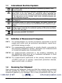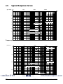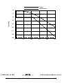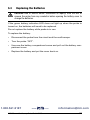
1
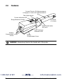
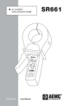
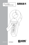
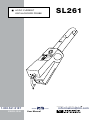
SL261 AC/DC CURRENT OSCILLOSCOPE PROBE I ZERO 100 mV/A 10 mV/A OFF 1.800.561.8187 ENGLISH www. User Manual .com [email protected] Statement of Compliance Chauvin Arnoux®, Inc. d.b.a. AEMC® Instruments certifies that this instrument has been calibrated using standards and instruments traceable to international standards. We guarantee that at the time of shipping your instrument has met its published specifications. An NIST traceable certificate may be requested at the time of purchase, or obtained by returning the instrument to our repair and calibration facility, for a nominal charge. The recommended calibration interval for this instrument is 12 months and begins on the date of receipt by the customer. For recalibration, please use our calibration services. Refer to our repair and calibration section at www.aemc.com. Serial #: _________________________________ Catalog #: 1201.51 Model #: SL261 Please fill in the appropriate date as indicated: Date Received: __________________________________ Date Calibration Due: ________________________ Chauvin Arnoux®, Inc. d.b.a AEMC® Instruments 1.800.561.8187 www.aemc.com www. .com [email protected] Table of Contents 1.INTRODUCTION................................................................................ 2 1.1 1.2 1.3 1.4 International Electrical Symbols.................................................3 Definition of Measurement Categories......................................3 Receiving Your Shipment...........................................................3 Ordering Information..................................................................4 1.4.1 Accessories and Replacement Parts.............................4 2. PRODUCT FEATURES....................................................................... 5 2.1 Description.................................................................................5 2.2 Compatibility..............................................................................5 2.3 Features.....................................................................................6 3.SPECIFICATIONS............................................................................. 7 3.1 3.2 3.3 3.4 3.5 Electrical Specifications.............................................................7 Mechanical Specifications.........................................................8 Environmental Specifications.....................................................9 Safety Specifications.................................................................9 Typical Response Curves........................................................10 4.OPERATION................................................................................... 12 4.1 4.2 4.3 4.4 Zero Adjustment.......................................................................12 Current Measurement..............................................................12 Battery Indication (Green LED)................................................13 Peak Overload (OL) Indication (Red LED)..............................13 5.MAINTENANCE.............................................................................. 14 5.1 Maintenance............................................................................14 5.2 Cleaning...................................................................................14 5.3 Replacing the Batteries............................................................15 Repair and Calibration............................................................................16 Technical and Sales Assistance.............................................................16 Limited Warranty....................................................................................17 Warranty Repairs....................................................................................17 1.800.561.8187 [email protected] www. .com CHAPTER 1 INTRODUCTION WARNING The safety warnings are provided to ensure the safety of personnel and proper operation of the instrument. Read the instruction completely. • Use caution on any circuit: potentially high voltages and currents may be present and may pose a shock hazard. • Do not use the probe if damaged. Always connect the current probe to the measuring device before it is connected around the conductor • Do not use on non insulated conductor with a potential to ground greater than 600V CAT III pollution 2. Use extreme caution when clamping around bare conductors or bus bars. • Before each use, inspect the probe; look for cracks in housing or output cable insulation. • Do not use clamp in wet environment or in locations that hazardous gases exist. • Do not use the probe anywhere beyond the tactile barrier. 1.800.561.8187 2 www. .com [email protected] AC/DC Current Oscilloscope Probe Model SL261 1.1 International Electrical Symbols This symbol signifies that the instrument is protected by double or reinforced insulation. This symbol on the instrument indicates a WARNING and that the operator must refer to the user manual for instructions before operating the instrument. In this manual, the symbol preceding instructions indicates that if the instructions are not followed, bodily injury, installation/sample and product damage may result. Risk of electric shock. The voltage at the parts marked with this symbol may be dangerous. This symbol refers to a type A current sensor. This symbol signifies that application around and removal from HAZARDOUS LIVE conductors is permitted. Probe fitted with an electronic output limiter providing protection against voltage surges caused by the accidental opening of the probe secondary circuit to 30V max. peak. In conformity with WEEE 2002/96/EC. 1.2 Definition of Measurement Categories CAT I: For measurements on circuits not directly connected to the AC supply wall outlet such as protected secondaries, signal level, and limited energy circuits. CAT II: For measurements performed on circuits directly connected to the electrical distribution system. Examples are measurements on household appliances or portable tools. CAT III: For measurements performed in the building installation at the distribution level such as on hardwired equipment in fixed installation and circuit breakers. CAT IV: For measurements performed at the primary electrical supply (<1000V) such as on primary overcurrent protection devices, ripple control units, or meters. 1.3 Receiving Your Shipment Upon receiving your shipment, make sure that the contents are consistent with the packing list. Notify your distributor of any missing items. If the equipment appears to be damaged, file a claim immediately with the carrier and notify your distributor at once, giving a detailed description of any 1.800.561.8187 [email protected] www. .com damage. Save the damaged packing container to substantiate your claim. AC/DC Current Oscilloscope Probe Model SL261 3 1.4 Ordering Information AC/DC Current Probe Model SL261 (10A-100mV/A, 100A-10mV/A, BNC)................................... Cat. #1201.51 Includes a user manual and a product warranty and registration card. 1.4.1 Accessories and Replacement Parts Adapter - BNC Adapter for use with AC/DC Current Probe Model SL261 & Meters 8220 & 8335................................... Cat. #2140.40 1.800.561.8187 4 www. .com [email protected] AC/DC Current Oscilloscope Probe Model SL261 CHAPTER 2 PRODUCT FEATURES 2.1Description The SL261 AC/DC Current Oscilloscope Probe expands oscilloscope applications in industrial, automotive or power environments, and is ideal for analysis and measurement of distorted current waveforms and harmonics. The probe permits accurate display and measurement of currents from 100mA to 100Arms, DC to 100kHz without breaking into the circuit. The probe uses Hall effect technology to measure AC and DC signals. The probe connects directly to an oscilloscope through a 2 meter coaxial cable with an insulated BNC. 2.2Compatibility The Model SL261 is compatible with any analog or digital oscilloscope or other voltage-measuring instrument which has the following features: • BNC input connector • Range capable of displaying 0.2 to 0.5V per division • Minimum input impedance of 1MΩ 1.800.561.8187 www. AC/DC Current Oscilloscope Probe Model SL261 .com [email protected] 5 2.3Features Current Flow for DC Measurements or Supply to Load for AC Measurements Zero Adjust Knob I RO ZE Power Indication LED Range Selection Switch F O A V/ m 0 /A 10 mV 10 F Ø = 0.46" (11.8 mm) Keep hands below this point Peak Overload Indication LED Battery Compartment Screw WARNING: Always keep hand on the handle part of the probe. 1.800.561.8187 6 Battery Compartment Cover www. .com [email protected] AC/DC Current Oscilloscope Probe Model SL261 CHAPTER 3 SPECIFICATIONS 3.1 Electrical Specifications *Reference conditions: 23°C ± 5°C, 20 to 75% RH, DC to 1kHz, probe zeroed, 1 minute warmup, batteries at 9V ± 0.1V, external magnetic field < 40 A/m, no DC component, no external current carrying conductor, 1MW/100pF load, conductor centered in jaw. Current Range: 100mV/A: 100mA to 10A peak 10mV/A: 1 to 100A peak Output Signal: 1000mV peak max AC Current Accuracy: After calibration and for one year (zero probe before making measurement) Range Accuracy Phase Shift 100mV/A (50mA to 10A peak) 3% of reading ± 50mA < 1.5° from DC to 65Hz 10mV/A (500mA to 40A peak) 4% of reading ± 50mA 10mV/A (40A to 100A peak) 15% max at 100A < 1° from DC to 65Hz Frequency Range: DC to 100kHz (-3dB with current derating) Noise: Range 10mV/A: 480µV Range 100mV/A: 3mV Slew Rate: Range 10mV/A: 20mV/µs Range 100mV/A: 0.3V/µs Load Impedance: > 1MW/100pF Insertion Impedance (50/60 Hz):100mV/A: 3µs 10mV/A: 0.01W 1.800.561.8187 www. AC/DC Current Oscilloscope Probe Model SL261 .com [email protected] 7 Rise or Fall Time: Range 100mV/A: 3µs Range 10mV/A: 4µs Working Voltage: 600Vrms max Common Mode Voltage: 600Vrms max Influence of Adjacent Conductor: < 0.2mA/A AC Influence of Conductor Position in Jaw: 0.5% of reading at kHz Battery: 9V alkaline (NEDA 1604A, IEC 6LR61) Low Battery: Green LED when ≥ 6.5V Overload Indication: Red LED indicates input greater than the selected range Typical Consumption: 8.6mA Battery Life: 55 hours typical 3.2 Mechanical Specifications Zero Adjustment: 20 turn potentiometer Maximum Cable Diameter: 0.46" (11.8 mm) Case Protection: IP20 per IEC 529 Drop Test: 1.0m on 38mm of oak on concrete; test according to IEC 1010 Mechanical Shock: 100G; test per IEC 68-2-27 Vibration: Test per IEC 68-2-6, frequency range 10 Hz to 55 Hz, amplitude 0.15mm Handle: Lexan® 920A, UL 94 V2 Dimensions: 9.09 x 1.42 x 2.64" (231 x 36 x 67mm) Weight: 11.6 oz (330g) with battery Color: Light gray Output Lead: Insulated coaxial cable with insulated BNC connector Cable Length: 6.5 foot (2m) 1.800.561.8187 8 www. .com [email protected] AC/DC Current Oscilloscope Probe Model SL261 3.3 Environmental Specifications Operating Temperature: 0° to 50°C (32° to 122°F) Storage Temperature: -30° to 80°C (-22° to 176°F) Operating Relative Humidity: 10° to 30° C: 85 ± 5% RH (without condensation) 40° to 50° C: 45 ± 5% RH (without condensation) Influence of Temperature: < 0.2% per °C Altitude:Non-operating: 0 to 12,000m Operating: 0 to 2000m 3.4 Safety Specifications Electrical: Double insulation or reinforced insulation between the primary or secondary and the outer case of the handle per EN 61010-2-032. 600V, CAT III, Pollution Degree: 2 Electromagnetic Compatibility: EN 50081-1 Class B EN 50082-2 Electrostatic discharge IEC 1000-4-2 Radiated Field IEC 1000-4-3 Fast Transients IEC 1000-4-4 Magnetic Field at 50/60 Hz IEC 1000-4-8 *Specifications are subject to change without notice 1.800.561.8187 www. AC/DC Current Oscilloscope Probe Model SL261 .com [email protected] 9 3.5 Typical Response Curves gain in dB 100 1000 10000 100000 Frequency in Hz 0 -1 range 100 mV/A -2 range 10 mV/A -3 -4 frequency response -5 measurement current: 1A sine Frequency phase in ° 100 10000 100000 0 Frequency in Hz -10 -50 range 10 mV/A -100 phase graph measurement current: 1A sine -150 range 100 mV/A Phase Shift 1.800.561.8187 10 www. .com [email protected] AC/DC Current Oscilloscope Probe Model SL261 Typical Specification 0% -2% -4% Uncertainty -6% -8% -10% -12% -14% -16% Accuracy 1.800.561.8187 0A 20A www. AC/DC Current Oscilloscope Probe Model SL261 40A .com 60A 80A 100A [email protected] 11 CHAPTER 4 OPERATION 4.1 Zero Adjustment The probe has a zero adjustment that should be adjusted before measurement. Alternatively, you may “zero” with the oscilloscope instead. 4.2 Current Measurement WARNING: Always connect the probe to the instrument before clamping onto the circuit under test. • Connect the Model SL261 to the proper input channel on the oscilloscope. • Begin with the least sensitive range on the current probe (10mV/A) • Select the 0.5V/Division range on the oscilloscope. • Clamp the probe on the conductor to be measured and read the current flowing directly on your oscilloscope. (Remember to unclamp the probe from the conductor before disconnecting it from your meter or instrument.) You may also use your oscilloscope to amplify the signal while using the 100mV/A probe range (which offers the best accuracy and least phase shift). NOTE: It is possible to change the range on the current probe without remov ing the probe from the current carrying conductor, but it is important to remember not to exceed the permissible peak ratings of 1000mV peak or 2000mV peak to peak maximum. The peak ratings by range are: 10A peak on the 100mV/A range, 100A peak.com on the 10mV/[email protected] range. 1.800.561.8187 www. 12 AC/DC Current Oscilloscope Probe Model SL261 4.3 Battery Indication (Green LED) The probe has a battery condition LED. To ensure proper readings with your current probe, be sure that the green LED is lit during measurement. If not, replace the 9V battery. 4.4 Peak Overload (OL) Indication (Red LED) The SL261 offers an overload indicator. If the red LED illuminates during measurement, this indicates that the peak value exceeds the instrument response level and that the output is distorted. Switch the probe to a higher range if possible. 1.800.561.8187 www. AC/DC Current Oscilloscope Probe Model SL261 .com [email protected] 13 CHAPTER 5 MAINTENANCE 5.1Maintenance WARNING • To ensure optimum performance, it is important to keep the probe jaw mating surfaces clean at all times. Failure to do so may result in error in readings. • For maintenance use only specified factory replacement parts. • To avoid electrical shock, do not attempt to perform any servicing unless you are qualified to do so. • To avoid electrical shock and/or damage to the instrument, do not allow water or other foreign substances into the case. • Disconnect the unit from all circuits and test cables before opening the case. 5.2Cleaning • To clean the probe body, use a soft cloth dampened in a solution of mild detergent and water. To clean the core, open the jaw and clean the exposed core surfaces with a cotton swab dampened with isopropyl alcohol (isopropanol) or ethyl alcohol (fotocol or ethanol). Lubricate the jaws mating surfaces with a light oil. • Do not use chemicals containing benzine, benzene, toluene, xylene, acetone, or similar solvents. • Do not immerse the probe in liquids or use abrasive cleaners. 1.800.561.8187 14 www. .com [email protected] AC/DC Current Oscilloscope Probe Model SL261 5.3 Replacing the Batteries CAUTION: Risk of electric shock. Disconnect all input(s) from the unit or remove the probe from any conductor before opening the battery cover to change the batteries. If the green battery indication LED does not light up when the probe is turned on, the batteries will need to be replaced. Do not replace the battery while probe is in use. To replace the battery: • Disconnect the probe from the circuit and the oscilloscope. • Turn the probe “OFF”. • Unscrew the battery compartment screw and pull out the battery compartment cover. • Replace the battery and put the cover back on. 1.800.561.8187 www. AC/DC Current Oscilloscope Probe Model SL261 .com [email protected] 15 Repair and Calibration To ensure that your instrument meets factory specifications, we recommend that it be scheduled back to our factory Service Center at one-year intervals for recalibration, or as required by other standards or internal procedures. For instrument repair and calibration: You must contact our Service Center for a Customer Service Authorization Number (CSA#). This will ensure that when your instrument arrives, it will be tracked and processed promptly. Please write the CSA# on the outside of the shipping container. If the instrument is returned for calibration, we need to know if you want a standard calibration, or a calibration traceable to N.I.S.T. (Includes calibration certificate plus recorded calibration data). Ship To: Chauvin Arnoux®, Inc. d.b.a. AEMC® Instruments 15 Faraday Drive Dover, NH 03820 USA Phone:(800) 945-2362 (Ext. 360) (603) 749-6434 (Ext. 360) Fax: (603) 742-2346 or (603) 749-6309 E-mail:[email protected] (Or contact your authorized distributor) Costs for repair, standard calibration, and calibration traceable to N.I.S.T. are available. NOTE: You must obtain a CSA# before returning any instrument. Technical and Sales Assistance If you are experiencing any technical problems, or require any assistance with the proper operation or application of your instrument, please call, mail, fax or e-mail our technical support team: Chauvin Arnoux®, Inc. d.b.a. AEMC® Instruments 200 Foxborough Boulevard Foxborough, MA 02035 USA Phone:(800) 343-1391 (508) 698-2115 Fax: (508) 698-2118 E-mail:[email protected] www.aemc.com NOTE: Do not ship Instruments to our Foxborough, MA address. 1.800.561.8187 16 www. .com [email protected] AC/DC Current Oscilloscope Probe Model SL261 Limited Warranty The AC/DC Current Oscilloscope Probe Model SL261 is warranted to the owner for a period of one year from the date of original purchase against defects in manufacture. This limited warranty is given by AEMC® Instruments, not by the distributor from whom it was purchased. This warranty is void if the unit has been tampered with, abused or if the defect is related to service not performed by AEMC® Instruments. For full and detailed warranty coverage, please read the Warranty Coverage Information, which is attached to the Warranty Registration Card (if enclosed) or is available at www.aemc.com. Please keep the Warranty Coverage Information with your records. What AEMC® Instruments will do: If a malfunction occurs within the one-year period, you may return the instrument to us for repair, provided we have your warranty registration information on file or a proof of purchase. AEMC® Instruments will, at its option, repair or replace the faulty material. REGISTER ONLINE AT: www.aemc.com Warranty Repairs What you must do to return an Instrument for Warranty Repair: First, request a Customer Service Authorization Number (CSA#) by phone or by fax from our Service Department (see address below), then return the instrument along with the signed CSA Form. Please write the CSA# on the outside of the shipping container. Return the instrument, postage or shipment pre-paid to: Ship To: Chauvin Arnoux®, Inc. d.b.a. AEMC® Instruments 15 Faraday Drive • Dover, NH 03820 USA Phone:(800) 945-2362 (Ext. 360) (603) 749-6434 (Ext. 360) Fax: (603) 742-2346 or (603) 749-6309 E-mail:[email protected] Caution: To protect yourself against in-transit loss, we recommend you insure your returned material. NOTE: You must obtain a CSA# before returning any instrument. 1.800.561.8187 www. AC/DC Current Oscilloscope Probe Model SL261 .com [email protected] 17 05/11 99-MAN 100042 10 1.800.561.8187 [email protected] ® ® Chauvin Arnoux www. , Inc. d.b.a. .com AEMC Instruments 15 Faraday Drive • Dover, NH 03820 USA • Phone: (603) 749-6434 • Fax: (603) 742-2346 www.aemc.com