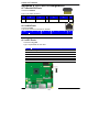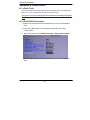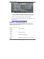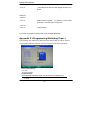
1
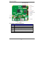
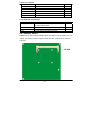
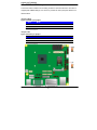
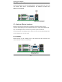
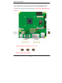
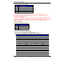
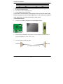
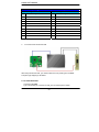
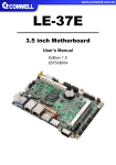
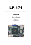
LN-D70
Nano-ITX Motherboard
User’s Manual
Edition 1.18
2015/06/26
LN-D70 User’s Manual
Copyright
Copyright 2014, all rights reserved. This document is copyrighted and all rights are
reserved. The information in this document is subject to change without prior notice to
make improvements to the products.
This document contains proprietary information and protected by copyright. No part of
this document may be reproduced, copied, or translated in any form or any means
without prior written permission of the manufacturer.
All trademarks and/or registered trademarks contains in this document are property of
their respective owners.
Disclaimer
The company shall not be liable for any incidental or consequential damages resulting
from the performance or use of this product.
The company does not issue a warranty of any kind, express or implied, including
without limitation implied warranties of merchantability or fitness for a particular
purpose.
The company has the right to revise the manual or include changes in the
specifications of the product described within it at any time without notice and without
obligation to notify any person of such revision or changes.
Trademark
All trademarks are the property of their respective holders.
Any questions please visit our website at http://www.commell.com.tw
TU
UT
Packing List:
Please check the package content before you starting using the board.
Hardware:
LN-D70 Mini-ITX Motherborad x 1
Cable Kit:
SATA Cable x 2
OALSATA3-L / (1040529)
Dual COM PORT Cable x 1
OALES-BKU2NB / (1040090)
USB2.0 Cable x 1
CRT cable without bracket x 1
(OALVGA-SNB-7)/ (1040557)
OALUSBA-3/ (1040173) (Option)
-2-
C Power Cable x 1
ALDC-A / (1040433)
LN-D70 User’s Manual
SATA Power Cable x 1
(OAL4P-S2)/ (1040054)
1 to 3 power output cable x 1
(OAL4P-2)/ (1040051)
DC Power Cable x 1
(OALDC-A)/ (1040433)
Audio Cable x 1
(OALPJ-HD-NB)/ (1040121)
Printed Matters:
Driver CD (Including User’s Manual) x 1
Cooler:
Heat Sink:
(OHSF-6) / (2181010018)
LN-D70JIP, LV-D70JX2
LN-D70EIP, LV-D70EX2
(OHS-8) / (2181110010)
LN-D70NIP, LN-D70NX2
-3-
LN-D70 User’s Manual
Index
Chapter 1 <Introduction> ..............................................................................5
1.1 <Product Overview>..................................................................................... 5
1.2 <Product Specification>................................................................................ 6
1.3 <Mechanical Drawing>................................................................................. 8
1.4 <Block Diagram>.......................................................................................... 9
Chapter 2 <Hardware Setup>........................................................................9
2.1 <Connector Location> .................................................................................. 9
2.2 <Jumper Location & Reference>................................................................ 10
2.3 <Connector Reference> ............................................................................. 11
2.3.1 <Internal Connectors> ................................................................... 11
2.4 < Memory Setup >...................................................................................... 12
2.5 <CMOS & ATX Setup> ............................................................................... 13
2.6 <Ethernet Interface>................................................................................... 14
2.7 <Onboard Display Interface> ..................................................................... 14
2.7.1 <Display>....................................................................................... 14
2.7.2 <LVDS> ......................................................................................... 15
2.7.3 <VGA Interface> ............................................................................ 18
2.8 <Integrated Audio Interface> ...................................................................... 19
2.9 <USB Interface>......................................................................................... 21
2.9.1 < USB 3.0 eXtensible Host Controller Driver install > .................... 21
2.10 <Serial Port> ............................................................................................ 25
2.11 <PCIE Mini Card and SIM Interface> ....................................................... 27
2.12 <GPIO and SMBUS Interface>................................................................. 30
2.13 <Power Supply and Fan Interface > ......................................................... 31
2.13.1 <Power Input> ............................................................................. 31
2.13.2 < Power Output >......................................................................... 32
2.13.3 <Fan connector>.......................................................................... 32
2.14 <Switch and Indicator>............................................................................. 33
Chapter 3 <System Setup> .........................................................................35
-4-
LN-D70 User’s Manual
3.1 <Audio Configuration>................................................................................ 35
3.2 <Display Properties Setting> ...................................................................... 35
3.3 <SATA configuration> ................................................................................. 37
Chapter 4 <BIOS Setup> .............................................................................38
Appendix A <I/O Port Pin Assignment>.....................................................39
A.1 <Serial ATA Port> ....................................................................................... 39
A.2 <LAN Port> ................................................................................................ 39
A.3 <LPC Port> ................................................................................................ 39
Appendix B <Flash BIOS> ..........................................................................40
B.1 <Flash Tool> .............................................................................................. 40
B.2 <Flash BIOS Procedure> ........................................................................... 40
Appendix C <Programming GPIO’s> .........................................................41
Appendix D <Programming Watchdog Timer > ........................................42
Contact Information.....................................................................................43
Chapter 1 <Introduction>
1.1 <Product Overview>
LN-D70 is the system-on-chip (SoC) designed for intelligent systems, delivering
outstanding compute, graphical, and media performance while operating in an extended
range of thermal conditions. These SoCs are based on the Silvermont microarchitecture,
utilizing Intel’s industry-leading 22nm process technology with 3-D Tri-Gate transistors,
which deliver significant improvements in computational performance and energy
efficiency.
New features for Intel® Celeron® and Atom Processor
The Intel® Celeron® Processor J1900 / N2930 and Intel® Atom E3845 Processor
supports, graphics, media performance, flexibility and more enhanced security that is
suitable for a variety of intelligent systems the ideal choice.
Outstanding integration of I/O interfaces
Supports display interfaces with graphics processing, camera interfaces with image
-5-
LN-D70 User’s Manual
processing, audio with digital signal processing, multiple storage types, and legacy
embedded I/O. Provides interface expansion capabilities through industry-standard
high-bandwidth interfaces such as PCI Express* Gen 2.0, Hi-speed USB 2.0, and USB
3.0 connectivity.
All in One multimedia solution
Based on Intel® J1900 / N2920 / E3845 SoC, the board provides high performance
onboard graphics, CRT, 24-bit dual channel LVDS interface, Display Port, DVI and two
channels High Definition Audio, to meet the very requirement of the multimedia
application.
Flexible Extension Interface
The board provides one PCIe mini slot and one SIM slot.
1.2 <Product Specification>
General Specification
Form Factor
CPU
Nano-ITX motherboard.
Bay Trail Intel® Celeron™ J1900 / N2930 and Atom™ E3845 Mobile
Processor.
Package Type: FCBGA1170.
Memory
1 x DDR3L (support 1.35V) 1066/1333 SO-DIMM up to 8GB.
Real Time Clock
Chipset integrated RTC with onboard lithium battery.
Watchdog Timer
Generates a system reset with internal timer for 1min/s ~ 255min/s.
Power Management
Supports ACPI 5.0 compliant.
Serial ATA Interface
2 x SATAII(3Gb/s), 2 x SATAIII(6Gb/s).
VGA Interface
Intel® Clear Video integrated HD Graphics Technology.
DVI Interface
Onboard DVI connector. (DVI and LVDS1 can’t be enabled simultaneously)
LVDS Interface
2 x Onboard 24-bit dual channel LVDS connector with +3.3V/+5V/+12V
supply.
Display port Interface Onboard Display port connector.
(Display port and LVDS2 can’t be enabled simultaneously)
Audio Interface
Realtek ALC262 High Definition Audio Codec.
LAN Interface
1 x Intel® I210 Gigabit LAN.
GPIO interface
Onboard programmable 8-bit Digital I/O interface.
Extended Interface
1 x PCIE Mini card or mSATA, 1 x SIM socket.
-6-
LN-D70 User’s Manual
Internal I/O Port
4 x RS232, 1 x GPIO, 1 x Audio connector, 1 x SMBUS connector, 1 x CRT, 2
External I/O Port
1 x PS/2 Keyboard/Mouse Port, 1 x RS232, 1 x RS232/422/485, 1 x DVI port,
x LVDS, 1 x LPC, 2 x USB 2.0 and 2 x SATAII, 2 x SATAIII.
1 x Display port, 1 x RJ45 LAN ports, 1 x USB 3.0(XHCI) port, 1 x USB 2.0
port.
Power Requirement
6~27V full range DC Input.
Dimension
120mm x 120mm. (L x W)
Temperature
Operating within 0~60 centigrade(for LN-D70J and LN-D70N serial)
Storage within -20~85 centigrade.(for LN-D70J and LN-D70N serial)
Operating within -40~85 centigrade(for LN-D70E serial)
Storage within -40~85 centigrade.(for LN-D70E serial)
Ordering Code
LN-70DJIP
Intel Celeron Processor J1900 (2M Cache, 2.42GHz), DVI, Display Port, CRT,
Gigabit LAN, USB3.0 & 2.0, Serial Port, SATAII, SATAIII, Audio, PCIE Mini
card, , SMBUS, GPIO, SIM, LPC, mSATA.
LN-70DEIP
Intel Atom Processor E3845 (2M Cache, 1.91GHz), DVI, Display Port, CRT,
Gigabit LAN, USB3.0 & 2.0, Serial Port, SATAII, SATAIII, Audio, PCIE Mini
card, SMBUS, GPIO, SIM, LPC, mSATA.
LN-70DNIP
Intel Celeron Processor N2930 (2M Cache, 2.16GHz), DVI, Display Port,
CRT, Gigabit LAN, USB3.0 & 2.0, Serial Port, SATAII, SATAIII, Audio, PCIE
Mini card, SMBUS, GPIO, SIM, LPC, mSATA.
LN-70DJX2
Intel Celeron Processor J1900 (2M Cache, 2.42GHz), 2 x LVDS, CRT, Gigabit
LAN, USB3.0 & 2.0, Serial Port, SATAII, SATAIII, Audio, PCIE Mini card,
SMBUS, GPIO, SIM, LPC, mSATA.
LN-70DEX2
Intel Atom Processor E3845 (2M Cache, 1.91GHz), 2 x LVDS, CRT, Gigabit
LAN, USB3.0 & 2.0, Serial Port, SATAII, SATAIII, Audio, PCIE Mini card,
SMBUS, GPIO, SIM, LPC, mSATA.
LN-70DNX2
Intel Celeron Processor N2930 (2M Cache, 2.16GHz), 2 x LVDS, CRT,
Gigabit LAN, USB3.0 & 2.0, Serial Port, SATAII, SATAIII, Audio, PCIE Mini
card, SMBUS, GPIO, SIM, LPC, mSATA.
The specifications may be different as the actual production.
For further product information please visit the website at http://www.commell.com.tw
TU
-7-
UT
LN-D70 User’s Manual
1.3 <Mechanical Drawing>
-8-
LN-D70 User’s Manual
1.4 <Block Diagram>
Chapter 2 <Hardware Setup>
2.1 <Connector Location>
-9 -
LN-D70 User’s Manual
2.2 <Jumper Location & Reference>
Jumper
JRTC
JVLCD
JAT
JP1
JP2
JCSEL1
JCSEL2
JMSATA
JVUSB
Function
CMOS Operating/Clear Setting
Panel1、2 Voltage Setting
Power mode select
Com1 Voltage Setting (For Pin 9)
Com2 Voltage Setting (For Pin 9)
COM2 RS-232 RS422 RS485 Setting
Mini Card mSATA Setting
USB Voltage Setting
-10-
LN-D70 User’s Manual
2.3 <Connector Reference>
2.3.1 <Internal Connectors>
Connector
CPU
SO-DIMM 1/2
SATAII 1/2
SATAIII 1/2
DC_IN
DC_OUT
CN_AUDIO
CN_DIO
CPUFAN
SYSFAN
CN_CRT
CN_LVDS 1/2
CN_INV 1/2
CN_COM 3/4/5/6
Function
FCBGA1170 CPU
204 -pin DDR3L SO-DIMM socket
7-pin Serial ATAII connector
7-pin Serial ATAIII connector
DC 6~27V input connector
4-pin DC output connector
5 x 2-pin audio connector
6 x 2-pin digital I/O connector
4-pin CPU cooler fan connector
4-pin system cooler fan connector
16-pin VGA connector
20 x 2-pin LVDS connector
5-pin LCD inverter connector
9-pin RS232
-11-
Remark
LN-D70 User’s Manual
CN_LPC
JFRNT
Mini-PCIE
JAT
SIMM
CN_SMBUS
CN_USB
5 x 2-pin LPC connector
14-pin front panel switch/indicator connector
52-pin Mini-PCIE socket
Power mode select
6-pin socket
5-pin SMBUS connector
5 x 2-pin USB2.0 connector
2.3.2 <External Connectors>
Connector
USB_RJ45 1/2
DVI + Display port
COM 1/2
PS/2
Function
1x USB3.0 / 2.0 , 1x USB2.0 ,
1x RJ45 LAN connector
DVI connect and Display port connector
Serial port connector
PS/2 keyboard and mouse connector
Remark
2.4 < Memory Setup >
LN-D70 has two 204-pin DDR3L DIMM support up to 8GB of memory capacity and 1.35
Voltage. The memory frequency supports 1066/1333 MHz. Only Non-ECC memory is
supported.
-12-
LN-D70 User’s Manual
2.5 <CMOS & ATX Setup>
The board’s data of CMOS can be setting in BIOS. If the board refuses to boot due to
inappropriate CMOS settings, here is how to proceed to clear (reset) the CMOS to its
default values.
Jumper: JRTC
Type: Onboard 3-pin jumper
JRTC
Mode
1-2
Clear CMOS
2-3
Normal Operation
Default setting: 2-3
Jumper: JAT
Type: onboard 3-pin jumper
JAT
Mode
1-2
AT Mode
2-3
ATX Mode
Default setting:2-3
-13-
LN-D70 User’s Manual
2.6 <Ethernet Interface>
The board integrates with Intel I210 Gigabit Ethernet, as the PCI Express bus. The Intel
I210 supports triple speed of 10/100/1000Base-T, with IEEE802.3 compliance and
Wake-On-LAN supported.
2.7 <Onboard Display Interface>
Based on Intel processor with built-in HD Graphic, the board provides one DVI
connector & one Display port on real external I/O port, two 40-pin LVDS interface with
5-pin LCD backlight inverter connector and provides 16-pin VGA interface.
The board provides dual display function with clone mode and extended desktop mode
for DVI, Display port, VGA and LVDS.
2.7.1 <Display>
Please connect your DVI & Display port or LCD monitor with male connector to the
onboard female connector on rear I/O port .
-14-
LN-D70 User’s Manual
2.7.2 <LVDS>
The board provides two 40-pin LVDS connector for 18/24-bit single/dual channel
panels, supports up to 1920 x 1080 resolution, with one LCD backlight inverter
connector and two jumper for panel voltage setting. Please install LVDS cable before
boot up.
Effective patterns of connection: 1-2 / 3-4 / 5-6
Warning: others cause damage
-15-
LN-D70 User’s Manual
Connector: CN_INV1 and CN_INV2
Type: 5-pin LVDS Power Header
Pin
Description
1
+12V
2
Reserved (Note)
3
GND
4
GND
5
ENABKL
Note1
1. LVDS1 (CN_INV1) and LVDS2 (CN_INV2) can be connected and enabled
simultaneously but the PWM feature will not function if both LVDS1 and LVDS2 are
enabled at the same time.
2. If you need PWM feature, an OEM model needs to be requested. But please be noted
that PWM function does not support on both LVDS. Either LVDS1 or LVDS2 can have
PWM feature supported. Please contact our Tech Support for detail information.
Connector: JVLCD
Type: 6-pin Power select Header
Pin
Description
1-2
LCDVCC (3.3V)
3-4
LCDVCC (5V)
5-6
LCDVCC (12V)
Default: 1-2
Connector: CN_LVDS1 and CN_LVDS2
Type: onboard 40-pin connector for LVDS connector
Connector model: HIROSE DF13-40DP-1.25V or compatible
Pin
2
4
6
8
10
12
14
16
18
20
22
24
26
28
30
32
Signal
LCDVCC
LVDSDET
ATX0ATX0+
GND
ATX1ATX1+
GND
ATX2ATX2+
GND
ACLKACLK+
GND
ATX3ATX3+
Pin
1
3
5
7
9
11
13
15
17
19
21
23
25
27
29
31
-16-
Signal
LCDVCC
GND
BTX0BTX0+
GND
BTX1BTX1+
GND
BTX2BTX2+
GND
BTX3BTX3+
GND
BCLKBCLK+
LN-D70 User’s Manual
34
36
38
40
GND
DDCPCLK
DDCPDATA
N/C
33
35
37
39
GND
N/C
N/C
N/C
To setup the LCD, you need the component below:
1. A panel with LVDS interfaces.
2. An inverter for panel’s backlight power.
3. A LCD cable and an inverter cable.
For the cables, please follow the pin assignment of the connector to make a cable,
because every panel has its own pin assignment, so we do not provide a standard
cable; please find a local cable manufacture to make cables.
LCD Installation Guide:
1.
Preparing the LN-D70, LCD panel and the backlight inverter.
2.
Please check the datasheet of the panel to see the voltage of the panel, and set
the jumper JVLCD to +12V or +5V or +3.3V.
3.
You would need a LVDS type cable.
Panel side
Board side
For sample illustrator only
-17-
LN-D70 User’s Manual
BIOS panel type selection form (BIOS Version:1.0)
Single / Dual channel
Single / Dual channel
NO.
Output format
1
640 x 480
9
1680 x 1050
2
800 x 600
10
1920 x 1200
3
1024 x 768
11
1440 x 900
4
1280 x 1024
12
1600 x 900
5
1400 x 1050
13
1024 x 768
6
1400 x 1050
14
1280 x 800
7
1600 x 1200
15
1920 x 1080
8
1366 x 768
4.
NO.
Output format
To connect all of the devices well.
After setup the devices well, you need to select the LCD panel type in the BIOS.
The panel type mapping is list below:
2.7.3 <VGA Interface>
Connector: CN_CRT
Type: onboard 16-pin connector for CN_CRT connector pitch 2.00mm
-18-
LN-D70 User’s Manual
Pin
1
3
5
7
9
11
13
15
Signal
BR
BB
-CRTATCH
IOGND1
NC
NC
5HSYNC
5VCLK
Pin
2
4
6
8
10
12
14
16
Signal
BG
NC
IOGND1
IOGND1
-CRTATCH
5VCDA
5VSYNC
NC
2.8 <Integrated Audio Interface>
The board integrates onboard audio interface with REALTEK ALC262 code, with Intel
next generation of audio standard as High Definition Audio, it offers more vivid sound
and other advantages than former HD audio compliance.
The main specifications of ALC262 are:
z
High-performance DACs with 100dB S/N ratio
-19-
LN-D70 User’s Manual
z
2 DAC channels support 16/20/24-bit PCM format for 2 audio solution
z
Compatible with HD
z
Meets Microsoft WHQL/WLP 2.0 audio requirements
Connector: CN_AUDIO
Type: 10-pin (2 x 5) header (pitch = 2.54mm)
Pin
1
3
5
7
9
Description
MIC_L
MIC_R
Speaker_R
SENSE
Speaker_L
Pin
2
4
6
8
10
-20-
Description
Ground
N/C
MIC Detect
N/C
Speaker Detect
LN-D70 User’s Manual
2.9 <USB Interface>
LN-D70 integrates 1 x USB3.0 / 2.0 and 3 x USB2.0 , The specifications of USB3.0 are
listed below:
Interface
USB3.0
Transfer Rate
Up to 5Gb/s
Voltage
5V
The USB3.0 port need to Install USB 3.0 eXtensible Host Controller Driver and
enable xHCI Mode.
2.9.1 < USB 3.0 eXtensible Host Controller Driver install >
Step1. Copy the USB 3.0 driver from “Driver CD” to the local hard driver directory.
( Do not run this driver from a USB storage device)
Step2. Configure default BIOS, click Advanced > South Cluster Configuration > USB
Configuration, disable “EHCI Mode”.
-21-
LN-D70 User’s Manual
Step3. enable “xHCI Mode” and push “F10” to save configuration. Restart your
computer.
1
Step4. If you enable xHCI Mode , USB 2.0 and USB 3.0 ports can’t use without
drive. We recommend that you connect PS/2 mouse / keyboard installing
USB 3.0 driver.
Step5. Double click the “Setup.exe” from the directory. Click “Next” to continue.
-22-
LN-D70 User’s Manual
Step6. Lastly, the “Setup Complete” screen appears so click “Finish” to
restart your computer.
The specifications of USB2.0 are list:
Interface
Transfer Rate
Voltage
USB2.0
Up to 480Mb/s
5V
-23-
LN-D70 User’s Manual
Connector: CN_USB
Type: 10-pin (2 x 5) header (pitch = 2.54mm)
Pin
1
3
5
7
9
Description
VCC (5V_SB/ 5V)
Data0Data0+
Ground
Ground
Pin
2
4
6
8
10
Description
VCC (5V_SB/ 5V)
Data1Data1+
Ground
N/C
CN_USB need to enable xHCI Mode.
Connector: JVUSB
Type: 6-pin Power select jumper
Pin
Description
1-3 & 2-4
5V_SB
3-5 & 4-6
5V
Default: 1-3 & 2-4
Effective patterns of connection: 1-3 & 2-4 or 3-5 & 4-6
-24-
LN-D70 User’s Manual
Warning: others cause damages
2.10 <Serial Port>
The board supports four RS232 serial port and one jumper selectable RS232/422/485
serial ports. The jumper JCSEL1 & JCSEL2 can let you configure the communicating
modes for COM2.
Connector: COM1
Type: 9-pin D-sub male connector on bracket for COM1
Pin
Description
Pin
Description
1
DCD
2
RXD
3
TXD
4
DTR
5
GND
6
DSR
7
RTS
8
CTS
9
RI
10
N/C
Connector: COM2
Type: 9-pin D-sub male connector on bracket for COM2
Pin
Description
Pin
Description
1
DCD/422TX-/4852
RXD/422TX+/485+
3
TXD/422RX+
4
DTR/422RX5
GND
6
DSR
7
RTS
8
CTS
9
RI
10
N/C
Setting RS-232 & RS-422 & RS-485 for COM2
Connector: COM3/4, COM5/6
-25-
LN-D70 User’s Manual
Type: 20-pin (2 x 10) header pitch = 2.54x1.27mm
Pin
Description
Pin
Description
1
DCD1
2
RXD1
3
TXD1
4
DTR1
5
GND1
6
DSR1
7
RTS1
8
CTS1
9
RI1
10
N/C
11
DCD2
12
RX2
13
TX2
14
DTR2
15
Ground
16
DSR2
17
RTS2
18
CTS2
19
RI2
20
N/C
-26-
LN-D70 User’s Manual
Function
JCSEL1
JCSEL2
RS-422
RS-485
RS-232
(Default)
Default setting:
JCSEL1: (1-3, 2-4, 7-9, 8-10) JCSEL2: (1-2)
Jumper: JP1/JP2 (COM1/2)
Type: onboard 6-pin header
Power Mode
JP1/2
Pin 9 with 5V Power
1-2
Pin 9 with 12V Power
3-4
Standard COM port
5-6
Default setting
2.11 <PCIE Mini Card and SIM Interface>
The board provides a PCIE mini card sockets and a SIM socket.
MINI_CARD is the Mini-PCIe slot for long size Mini-PCIe cards and supports mSATA.
Connector: SIMM (3G MiniPcie Model)
Type: 6-pin SIM socket
Pin
Description
Pin
Description
1
SIMVCC
2
SIMRST
3
SIMCLK
4
NC
-27-
LN-D70 User’s Manual
5
GND
6
7
SIMDATA
SIMVPP
Jumper: JMSATA
Type: onboard 3-pin header
MINI_CARD Mode
JMSATA
Supply mSATA
1-2(Note)
MINI_CARD
Default setting:
2-3
2-3
Note:SATA2-2 and mSATA can’t be enabled simultaneously
2.11.1 <SIM Setup>
Step1.
SIM card holder is marked by circle.
Slide the cap toward OPEN direction.
-28-
LN-D70 User’s Manual
Step 2.
Make sure that the cap is now at the OPEN position.
Step 3.
Flip the cap up for inserting a SIM card into.
Step 4.
Insert a SIM card as shown in the photo.
Be sure that the corner cut is on top and the golden pads are up.
Step 5.
Now, flip down the cap as shown in the photo.
-29-
LN-D70 User’s Manual
Step 6.
Press down and slide the cap to the CLOSE position. Be sure that the cap is tightly held
with the socket.
2.12 <GPIO and SMBUS Interface>
The board provides a programmable 8-bit digital I/O interface; you can use this general
purpose I/O port for system control like POS or KIOSK. The GPIO is an Open-drain
output and TTL-level input.
1.
2.
Output:Open-drain, Most applications need use an external pull-up resistor.
Input:TTL-level.
DC characteristics:
5V TTL-level Input Pin
Parameter
Input Low Voltage
Input High Voltage
Input High Leakage
Input Low Leakage
Sym
VIL
VIH
ILIH
ILIL
Min
Typ
Max
0.8
2.0
+10
-10
Unit
V
V
μA
μA
Conditions
VIN = 3.3V
VIN = 0V
open-drain output pin with 12-mA sink capability
Output Low Voltage
VOL
0.4
Connector: CN_DIO
Type: 12-pin (6 x 2) header (pitch = 2.0mm)
Pin
1
3
5
7
9
11
Description
Ground
GPIO0
GPIO1
GPIO2
GPIO3
5V
Pin
2
4
6
8
10
12
-30-
Description
Ground
GPIO4
GPIO5
GPIO6
GPIO7
12V
V
IOL = 12 mA
LN-D70 User’s Manual
Connector: CN_SMBUS
Type: 5-pin header for SMBUS Ports
Pin
1
2
3
4
5
Description
VCC
N/C
SMBDATA
SMBCLK
Ground
2.13 <Power Supply and Fan Interface >
2.13.1 <Power Input>
The board requires onboard 4-pin DC-input connector voltage range is from 6V to 24V, ,
for the input current, please take a reference of the power consumption report on
appendix.
-31-
LN-D70 User’s Manual
Connector: DC_IN
Type: 4-pin standard Pentium 4 additional +12V power connector
Pin
Description
Pin
Description
1
Ground
2
Ground
3
+6V~+24V
4
+6V~+24V
2.13.2 < Power Output >
Connector: DC_OUT
Type: 4-pin connector for +5V/+12V output
Pin
1
Description
+12V
Pin
2
Description
Ground
Pin
3
Description
Ground
Pin
4
Description
+5V
Note: Maximum output current 12V/3A, 5V/3A
2.13.3 <Fan connector>
The board provides one 4-pin fan connectors supporting smart fan for CPU cooler and
one 4-pin cooler fan connectors for system.
-32-
LN-D70 User’s Manual
Connector: CPUFAN
Type: 4-pin fan wafer connector
Pin
Description
1
Ground
3
Fan Speed Detection
Connector: SYSFAN
Type: 4-pin fan wafer connector
Pin
Description
1
Ground
3
Fan Speed Detection
Pin
2
4
Description
+12V
Fan Control
Pin
2
4
Description
+12V
Fan Control
2.14 <Switch and Indicator>
The JFRNT provides front control panel of the board, such as power button, reset and
beeper, etc. Please check well before you connecting the cables on the chassis.
Connector: JFRNT
Type: onboard 14-pin (2 x 7) 2.54-pitch header
Function
Signal
PIN
-33-
Signal
Function
LN-D70 User’s Manual
HDLED+
1
2
PWRLED+
HDLED-
3
4
N/C
Reset+
5
6
PWRLED-
Reset-
7
8
SPK+
N/C
9
10
N/C
Power
PWRBT+
11
12
N/C
Button
PWRBT-
13
14
SPK-
IDE LED
Power
LED
Reset
Speaker
-34-
LN-D70 User’s Manual
Chapter 3 <System Setup>
3.1 <Audio Configuration>
The board integrates REALTEK® ALC262 code. It can support 2-channel sound under
system configuration. Please follow the steps below to setup your sound system.
1.
Install REALTEK HD Audio driver.
2.
Lunch the control panel and Sound Effect Manager.
3.
Select Speaker Configuration
3.2 <Display Properties Setting>
Based on Intel J1900/N2930 with HD Graphic, the board supports two DACs for display
device as different resolution and color bit.
Please install the Intel Graphic Driver before you starting setup display devices.
-35-
LN-D70 User’s Manual
1. Click right button on the desktop to lunch Screen resolution > Advanced settings
2. Click Graphics Properties… button for more specificity setup.
Click Graphics Properties... for
advanced setup
3. This setup options can let you define each device settings.
-36-
LN-D70 User’s Manual
3.3 <SATA configuration>
SATA Mode:
This option can let you select whether the Serial ATA hard drives would work under
normal IDE or AHCI.
-37-
LN-D70 User’s Manual
Chapter 4 <BIOS Setup>
The motherboard uses the Phoenix BIOS for the system configuration. The Phoenix
BIOS in the single board computer is a customized version of the industrial standard
BIOS for IBM PC AT-compatible computers. It supports Intel x86 and compatible CPU
architecture based processors and computers. The BIOS provides critical low-level
support for the system central processing, memory and I/O sub-systems.
The BIOS setup program of the single board computer let the customers modify the basic
configuration setting. The settings are stored in a dedicated battery-backed memory,
NVRAM, retains the information when the power is turned off. If the battery runs out of
the power, then the settings of BIOS will come back to the default setting.
The BIOS section of the manual is subject to change without notice and is provided here
for reference purpose only. The settings and configurations of the BIOS are current at
the time of print, and therefore they may not be exactly the same as that displayed on
your screen.
To activate CMOS Setup program, press <DEL> key immediately after you turn on the
system. The following message “Press DEL to enter SETUP” should appear in the lower
left hand corner of your screen. When you enter the CMOS Setup Utility, the Main Menu
will be displayed as Figure 4-1. You can use arrow keys to select your function, press
<Enter> key to accept the selection and enter the sub-menu.
Figure 4-1 CMOS Setup Utility Main Screen
-38-
LN-D70 User’s Manual
Appendix A <I/O Port Pin Assignment>
A.1 <Serial ATA Port>
Connector: SATA1/2
Type: 7-pin wafer connector
1
2
7
3
4
5
1
6
7
GND RSATA_TXP1 RSATA_TXN1 GND RSATA_RXN1 RSATA_RXP1 GND
A.2 <LAN Port>
Connector: RJ45
Type: RJ45 connector with LED on bracket
Pin
Description
8
1
2
3
4
5
MI0+
MI0-
MI1+
MI2+
6
MI2- MI1-
7
8
MI3+
MI3-
A.3 <LPC Port>
Connector: CN_LPC
Type: 10-pin header for LPC Port
Pin
1
3
5
7
9
11
Description
LPC_CLK
-LFRAME
LAD2
LAD0
SERIRQ
3.3V
Pin
2
4
6
8
10
12
-39-
1
Description
RESETLAD3
LAD1
+3.3V
Ground
N/C
LN-D70 User’s Manual
Appendix B <Flash BIOS>
B.1 <Flash Tool>
The board is based on Phoenix BIOS and can be updated easily by the BIOS auto
flash tool. You can download the tool online from below link
http://www.commell.com/Support/Product%20Technical%20Support/LN-D70.
htm
B.2 <Flash BIOS Procedure>
1.Extract the zip file(re-flash tool and BIOS file) to root of the USB flash
drive.
2.Insert your USB flash drive in USB port of the board and power
on the system.
3. Boot to EFI-Shell mode (UEFI Boot Enable, Legacy Boot Disable)
then input the “fs0:” command to switch to the root of the USB flash
drive.
-40-
LN-D70 User’s Manual
4. Type the ” fpt64.efi -y -f xxx.bin” command to start flash BIOS
processes. ( xxx.bin means the BIOS file that you want to update)
5. When it finished all update processes, restart the system.
Any question about the BIOS re-flash please contact your distributors or visit the
web-site at below:
http://www.commell.com.tw/support/support.htm
UT
Appendix C <Programming GPIO’s>
The GPIO’ can be programmed with the MSDOS debug program using
simple IN/OUT commands. The following lines show an example how to
do this. (The GPIO is open drain)
GPIO0…..GPIO7 bit0……bit7
-o 4E 87
;enter configuration
-o 4E 87
-o 4E 07
-o 4F 07
;enale GPIO function
-o 4E 30
-o 4F 10
;enable GPIO configuration
-o 4E F0
-o 4F xx
;set GPIO as input/output; set ‘1’ for input,’0’for
output
-41-
LN-D70 User’s Manual
-o 4E F1
-o 4F xx
;if set GPIO’s as output,in this register its value can
be set
Optional :
-o 4E F2
-o 4F xx
; Data inversion register ; ‘1’ inverts the current valus
of the bits ,’0’ leaves them as they are
-o 4E 30
-o 4F 01
; active GPIO’s
For further information, please refer to NCT6106D datasheet.
Appendix D <Programming Watchdog Timer >
The watchdog timer makes the system auto-reset while it stops to work for a period.
The integrated watchdog timer can be setup as system reset mode by program.
Timeout Value Range
- 1 to 255
- Second or Minute
Program Sample
The integrated Watchdog Timer can be set up by programming.
Enter configuration
-O 4E 87
-O 4E 87
-42-
LN-D70 User’s Manual
-O 4E 07
-O 4F 08
-O 4E 30
-O 4F 01
-O 4E F0
-O 4F 00
-O 4E F1
-O 4F 0A
Logic Device Enable
WDT Enable
Set as Second*
Set reset time 10 Sec
You can select Timer setting in the BIOS, after setting the time options, the system
will reset according to the period of your selection.
Contact Information
Any advice or comment about our products and service, or
anything we can help you please don’t hesitate to contact with us.
We will do our best to support you for your products, projects and
business.
Taiwan Commate Computer Inc.
19F., No.94, Sec. 1, Xintai 5th Rd., Xizhi Dist., New Taipei
Address
City 22102, Taiwan
TEL
+886-2-26963909
FAX
+886-2-26963911
http://www.commell.com.tw
Website
TU
UT
[email protected] (General Information)
TU
UT
E-Mail
[email protected] (Technical Support)
TU
Facebook
Twitter
UT
https://www.facebook.com/pages/Taiwan-Commate-Computer-Inc/547993955271899
https://twitter.com/Taiwan_Commate
Commell is a brand name of Taiwan commate computer Inc.
-43-