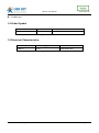
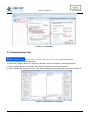
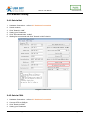
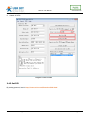
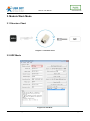
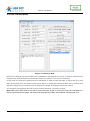
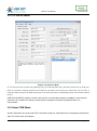
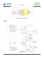
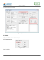
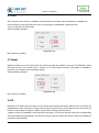
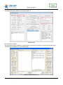
1
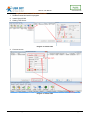
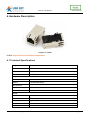
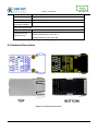
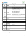
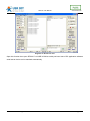
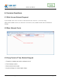
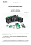
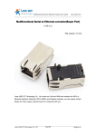
USR-K1 User Manual www.usriot.com USR-K1 Super Port File version: V1.0.3 USR-K1 is the high performance-cost version of Super Port .It is an embedded serial networking module, whose function is to realize bidirectional transparent transmission between UART TTL and Ethernet .The amazing part of K1 lies in its Ethernet port integration design .You can apply K1 to your products to realize networking communication .User can directly process data interaction through network and device to realize remote data acquisition, remote control and management. K1 is based on the design concept of "Simple,Reliable,Affordable" .And it has the same kernel solution and parameters as USR-TCP232-T. Jinan USR IOT Technology Limited 1 / 29 [email protected] USR-K1 User Manual www.usriot.com Content USR-K1 Super Port .............................................................................................................................. 1 1.Product Introduction ...................................................................................................................... 3 1.1 Brief Intro ............................................................................................................................... 3 1.2 Function Features................................................................................................................... 3 1.3 Product Characteristics ........................................................................................................... 3 1.4 Order Symbol ......................................................................................................................... 4 1.5 Electrical Characteristics ......................................................................................................... 4 2. Default Parameter Test .................................................................................................................... 5 2.1 Hardware Connection ............................................................................................................. 5 2.2 Set-up Software...................................................................................................................... 6 2.3 Communication Test ............................................................................................................... 7 2.4 Parameter Setting................................................................................................................... 8 2.4.1 Set via Net .................................................................................................................... 8 2.4.2 Set via COM. ................................................................................................................. 8 2.4.3 Set DIY......................................................................................................................... 9 3. Module Work Mode ....................................................................................................................... 10 3.1 Structure Chart ..................................................................................................................... 10 3.2 UDP Mode ........................................................................................................................... 10 3.3 TCP Client ........................................................................................................................... 11 3.4 UDP Server Mode................................................................................................................. 12 3.5 TCP Server Mode ................................................................................................................. 13 3.6 Virtual COM Mode ................................................................................................................ 13 4. Hardware Description .................................................................................................................... 15 4.1 Technical Specifications......................................................................................................... 15 4.2 Hardware Description............................................................................................................ 16 4.3 Hardware to RJ45 Light ......................................................................................................... 17 4.4 Size .................................................................................................................................... 18 5. Expand Functions .......................................................................................................................... 19 5.1 RS485 ................................................................................................................................. 19 5.2 Link ..................................................................................................................................... 20 5.3 Reset .................................................................................................................................. 20 5.4 ID........................................................................................................................................ 20 5.5 Index ................................................................................................................................... 22 5.6 RFC2217 ............................................................................................................................. 23 6. Common Questions ....................................................................................................................... 26 6.1 Work Across Network Segment .............................................................................................. 26 6.2 More Network Cards ............................................................................................................. 26 6.3 Every Period of Time, Module Dropped ................................................................................... 26 6.4 Search Device Failure, Port Occupied..................................................................................... 27 7. Revison history ............................................................................................................................. 28 8. Contact Us ................................................................................................................................... 29 Jinan USR IOT Technology Limited 2 / 29 [email protected] USR-K1 User Manual www.usriot.com 1.Product Introduction 1.1 Brief Intro USR-K1 is the high performance-cost version of Super Port. It is an embedded serial networking module, whose function is to realize bidirectional transparent transmission between TTL and Ethernet. The amazing part of K1 lies in its Ethernet port integration design .You can apply K1 to your products to realize networking communication .User can directly process data interaction through network and device to realize remote data acquisition, remote control and management. K1 is based on the design concept of "Simple,Reliable, Affordable". And it has the same kernel solution and parameters as USR-TCP232-T. 1.2 Function Features 10/100M auto detect interface; Support AUTO MDI/MDIX, Can use a crossover cable or parallel cable connection; Serial com port bound rate can set up from 300 to 961200,and None,Odd,Even,Mark,Space five check bits; Work mode TCP Server, TCP Client, UDP, UDP Server; Working model related parameters can be set via a serial port or network; 3.3 V TTL level compatible; Small Size Virtual serial port supported; Unique heartbeat package mechanism to ensure that the connection is reliable, put an end to connect feign death; Under UDP mode, Packet Broadcast is prohibited, with stronger anti-interference ability; Across the gateway, across switches, routers; Can work in LAN, also can work on the Internet (external network); 1.3 Product Characteristics 32 bits ARM CPU inside; LAN : 10/100Mbps; protect: Built-2KV isolated electromagnetic; Serial port baud rate: from 2400 to 961.2 KBPS can be set up; Network protocol: ETHERNET ARP IP UDP TCP ICMP; Software tool: configuration software, TCP/UDP test soft, RS232 debug soft; Configuration method: serial com port or via Ethernet, free software available; Operating temperature: -25~75°C; Jinan USR IOT Technology Limited 3 / 29 [email protected] USR-K1 User Manual www.usriot.com Storage environment: -40~85°C, 5~95%RH. Compact type 1.4 Order Symbol name symbol Super Port USR-K1 Description Remarks Diagram 0-1 order symbol 1.5 Electrical Characteristics Model number Power supply DC current USR-K1 3.3V 185mA(165-195) Diagram 0-2 Electrical Characteristics Jinan USR IOT Technology Limited 4 / 29 [email protected] USR-K1 User Manual www.usriot.com 2. Default Parameter Test Pls connect the product with your computer or router to test its performance. FAQ: http://www.usriot.com/Search/getList/keyword/t24/ 2.1 Hardware Connection 1.You can using” USR-TCP232-EVB”. It's easier to test. USR-TCP232-EVB is power for DC 5V@200mA. Diagram 2-1 USR-K1 Connection diagram 3.If you don’t have “USR-TCP232-EVB”,please refer to 5.4 Jinan USR IOT Technology Limited 5 / 29 [email protected] USR-K1 User Manual www.usriot.com 2.2 Set-up Software Set-up Software with link http://www.usriot.com/Download/237.html as can help to view default setting then set the parameter. 1. Search in LAN (Firstly, ensure the computer IP is static. The module IP is 192.168.0.201by default; Disable firewall, antivirus soft and WIFI). Diagram 2-2 the default parameters 2.Keep default parameter set up your pc. Jinan USR IOT Technology Limited 6 / 29 [email protected] USR-K1 User Manual www.usriot.com Diagram 2-3 pc parameter 2.3 Communication Test (link http://www.usriot.com/Download/199.html ) can help you test. Serial to net debugging tester application: 1. Ensure the COM port baud rate, check bits, data bits, stop bit correspond to module parameters. 2. Ensure network protocol, IP address, port number correspond to module parameters. 3. Open COM and the web then connect. They begin transparent transmission after choose the module IP. Diagram 2-4 USR-TCP232-Test Parameter Jinan USR IOT Technology Limited 7 / 29 [email protected] USR-K1 User Manual www.usriot.com 2.4 Parameter Setting 2.4.1 Set via Net 1. 2. 3. 4. 5. 6. Hardware Connection,refer to 2.1 Hardware Connection Search module, Click ”Search in LAN” Setting your Parameter Click ”Set selected item via Net” Waiting for ten seconds and Click ”Search in LAN” check it. Diagram 2-5 Set via net 2.4.2 Set via COM. 1. 2. 3. 4. Hardware Connection,refer to 2.1 Hardware Connection Connect CFG to GND pin Click ”Read via COM” Setting your Parameter Jinan USR IOT Technology Limited 8 / 29 [email protected] USR-K1 User Manual www.usriot.com 5. Click ”Read via COM” and check it 6. Switch off CFG. Diagram 2-6 Set via COM 2.4.3 Set DIY By setting protocol, load in http://www.usriot.com/Download/206.html Jinan USR IOT Technology Limited 9 / 29 [email protected] USR-K1 User Manual www.usriot.com 3. Module Work Mode 3.1 Structure Chart Diagram 3-1 structure chart 3.2 UDP Mode Diagram 3-2 UDP Mode Jinan USR IOT Technology Limited 10 / 29 [email protected] USR-K1 User Manual www.usriot.com In UDP mode, after the module is powered on listening on port Settings, not take the initiative to establish a connection, when data from by forwarding to the serial port, when a serial port receives the data sent over the network to the IP and port module Settings. 3.3 TCP Client Diagram 3-3 TCP Client In TCP client mode, after power on module according to their own Settings active TCP server to connect to the server, and then establish a long connection, data transparent transmission after this mode, the TCP server IP module would need to be visible and the visible means directly by module's IP can PING the server IP, server side can be fixed IP, the Internet can also be internal network IP and module in the same local area network. Jinan USR IOT Technology Limited 11 / 29 [email protected] USR-K1 User Manual www.usriot.com 3.4 UDP Server Mode Diagram 3-4 UDP Server Mode UDP server refers to the normal UDP are not validated on the basis of the source IP address, destination IP instead of the UDP packets are received data source IP, similar to TCP server functionality. In this mode, the module by default record a destination IP, when a serial port data, to record the IP to send data, at the same time, the module at the server status, to accept the network packets sent to module, and adjust the target IP IP for the data source, suitable for multiple IP working mode for the module. Use computer end program and UDP mode is exactly the same, no need to change. Note:UDP mode, UDP server mode with a single maximum length of 1472 bytes should be controlled at or below, if greater than this length, the module will automatically restart, the proposed subcontractor sent. Jinan USR IOT Technology Limited 12 / 29 [email protected] USR-K1 User Manual www.usriot.com 3.5 TCP Server Mode Diagram 3-5 TCP Server Mode In TCP Server mode, module and gateway trying to communication first, and then monitor set up local port, there is connection request response and create a connection, can exist at the same time up to 4 links, a serial port after receipt of the data will be sent to all at the same time of establishing links with network module device. USR-TCP232-SETUP software, set the Index function can be achieved when to establish a multi-channel connection, the module can identify communications equipment, and with the specified device to communicate. 3.6 Virtual COM Mode Virtual COM means to convent data TCP connected to data of a COM within PC for transparent transmission. Take TCP Client mode for example: Jinan USR IOT Technology Limited 13 / 29 [email protected] USR-K1 User Manual www.usriot.com Loading http://www.usriot.com/Download/31.html 1. Disable firewall and antivirus program 2. Install Virtual COM 3. Setting TCP Server Diagram 3-6 Virtual COM 4. Connect a com Diagram 3-7 Virtual COM Jinan USR IOT Technology Limited 14 / 29 [email protected] USR-K1 User Manual www.usriot.com 4. Hardware Description Diagram 4-1 USR-K1 PCB lib: http://www.usriot.com/Download/232.html 4.1 Technical Specifications Major characteristic Parameter Name USR-K1 CPU 32bit 48MHz(Cortex-M0) Flash 32KBit RJ45 Socket 1 Speed 10/100M MDI/MDIX Net protocol IP,TCP,UDP,ARP,ICMP Buffer send: 2K bytes,receive: 1K bytes Network interface 8 pin RJ45 Serial Port Number 1 Interface Standard TTL: pin type 3.3V Data Bits 5,6,7,8 Stop Bit 1,1.5,2 Check Bit None,Even,Odd,Space,Mark Jinan USR IOT Technology Limited 15 / 29 [email protected] USR-K1 User Manual Baud Rate TTL:110 bps ~ 921.6 Kbps Flow Control null Buffer receive: 800 bytes RS-485 Pull-up and Pull-Down Resistor null,reserved 485 send-receive control pin www.usriot.com Parameter specification Physical Size: PCB size: 21.6*13.5*32.6MM(L*H*W) Temperature and humidity range Operating temperature: -25 to 75 °C Storage temperature: -40 to 80 °C Storage humidity: 5% to 95% RH Diagram 4-2 Technical Specifications 4.2 Hardware Description Diagram 4-3 Technical Specifications Jinan USR IOT Technology Limited 16 / 29 [email protected] USR-K1 User Manual www.usriot.com No. Pin Function Descriptions 1 ISP Update pin This pin to ground to the module power module can be upgraded.If you do not use, can be suspended. 2 N/C N/C N/C 3 LINK Can be used as a network connection status indicator pin Pin received 200ms low to reset the whole module. If you do not use, can be suspended. 4 RST RESET Note: The module is powered automatic reset, it is recommended that connect the MCU IO port, reset the MCU control module in a particular case. 5 485_EN 485 enable Can be used as RS485 enable pin 6 Low, you can use the serial port module configuration. CFG Serial ports Normal working hours left floating or tied HIGH. Configuration pins Note: give the power module, and then pulled down the CFG pin to enter the serial configuration state. 7 LED2 Network data instructions Connect to 13 8 RXD Module data is received Data receiving end of the module, TTL 3.3V microcontroller TXD Module data transmission Data transmission end of the module, TTL level can be connected to 5V or 3.3V microcontroller 10 GND Signal ground GND 11 VCC Power supply Power supply: 3.3V @ 200mA 12 LED1 Network connection status indicator Connect to 16 13 LED2 Network data instructions Connect to 7 14 LED_3. 3 Network led power 15 LED_3. 3 Network led power 16 LED1 Network connection status indicator 9 Power 3.3V Power 3.3V Connect to 12 Diagram 4-3 I/O introduce 4.3 Hardware to RJ45 Light Jinan USR IOT Technology Limited 17 / 29 [email protected] USR-K1 User Manual www.usriot.com Diagram 4-4 Hardware to RJ45 light 4.4 Size Diagram 4-5 size Jinan USR IOT Technology Limited 18 / 29 [email protected] USR-K1 User Manual www.usriot.com 5. Expand Functions Diagram5-1 Expand functions 5.1 RS485 “485_en” for RS485, external enable control pin. Set the software interface: Diagram5-2 RS485 Select it by default Jinan USR IOT Technology Limited 19 / 29 [email protected] USR-K1 User Manual www.usriot.com 5.2 Link The Link pins for the module to establish a communication connection status indicates pin, establish the communication Link pin will output low level, no connection is established, output high level. "Link" for external Link instructions . Set the software interface: Diagram5-3 Link Don’t select it by default 5.3 Reset When the module as a TCP Client-side, the module will take the initiative to connect TCP SERVER. When the Reset function, the module tries to connect to TCP Server-side 30 times, still unable to establish a connection, the module will automatically restart. Set the software interface: Diagram5-3 Link Don’t select it by default 5.4 ID Module as TCP Client-side ID function for TCP Server-side distinguish between data sources, to achieve the establishment of the connection or data communication process device ID will also be sent, the module ID number is set to decimal, range 0 - 65535, requires the receiving end HEX format. 1.Select "Connect" to establish a communication connection, TCP Server-side will receive the corresponding TCP Client-side ID (ID Description: The first four shows for the ID number, the last four digits of the display ID negated to authentication). Jinan USR IOT Technology Limited 20 / 29 [email protected] USR-K1 User Manual www.usriot.com The following picture shows the module do TCP CLINENT establish a communication connection ID feature is enabled, the setup interface module ID number 12 Diagram5-4 ID Don’t select it by default The figure below shows establish a communication connection ID function, the device through the serial communication interface to the TCP Server-side: Diagram5-5 USR-TCP232-Test ID Jinan USR IOT Technology Limited 21 / 29 [email protected] USR-K1 User Manual www.usriot.com 2.Select data during each data transfer, TCP Server-side will receive the corresponding TCP Client-side ID (ID Description: ID before data transmitted only display four-digit ID number). The following picture shows the module do the TCP CLINENT ID feature is enabled, data transmission module ID number 12 setting interface: Diagram5-6 USR-TCP232-Test ID The figure below shows the data communication ID function, the device through the serial port to TCP Server communication interface: 5.5 Index Module as TCP SERVER end up at the same time to establish four connections, server-side at the same time send data to four CLIENT and SERVER the receiving Client-side data can not distinguish between sources of data, the Index function can send and receive data source selection. Index function is enabled, communication data is displayed corresponding Client side device number, specific parameters are described below: 1.When receive data from Ethernet, module will send data to serial port with head 49 N ,followed by data. 49 represent incoming data, N represent client index. 2.When user MCU want send data to module serial port, start with head 4F N data... 4F represent send out, N represent which client. 3.When new TCP connection incoming, module will send 43 N M to serial port, indicating that there is current link N accessed, total link number M. 4.When link number have exceed maximum, new link requirement will lead to message 46 46. 5.When disconnect, module will send 44 N M, represent current link N is delete, left link M. Jinan USR IOT Technology Limited 22 / 29 [email protected] USR-K1 User Manual www.usriot.com Note: The above values set are HEX format. Set the software interface: Diagram5-7 Index Don’t select it by default Diagram5-7 the test of index 5.6 RFC2217 RFC2217 is an agreement for setup com port settings via Ethernet by socket, Our product support an agreement like that, but not standard RFC2217, it is more sample and easy than RFC2217. 1. When module receive setup command, if is a valid command(right packet head and right checksum), the module will change self setting and answer nothing, else the data bits would be sent out at com port. 2. TCP Client, TCP Server, UDP Client, UDP Server, UDP broadcast support this function. 3. All changes will work at once, but not save to module, when power off will lose the settings. Set the software interface: Jinan USR IOT Technology Limited 23 / 29 [email protected] USR-K1 User Manual www.usriot.com Diagram5-8 RFC2217 select it by default The command length is 8 bits, detail as follow table. The demo bytes are in hex mode: Name Packet header Band rate UART bits setting Check sum Bytes 3 3 1 1 Description Three bytes Band rate in hex mode, High byte first. Parity/data/stop settings, see follow table. Check sum of last 4 bytes For example (115200,N,8,1) 55 AA 55 01 C2 00 83 83 For example (9600,N,8,1) 55 AA 55 00 25 80 83 83 Diagram5-9 RFC2217 introduce Appendix: UART bits setting detail. Bit Description Value Description 1:0 Data bits 00 5 bits 01 6 bits 10 7 bits 11 8 bits 0 1 bits 1 2 bits 0 Not enable Parity 1 Enable Parity 00 ODD 01 EVEN 10 Mark 11 Clear 000 Please fill 0 2 3 5:4 8:6 Stop bits Parity enable Parity type Not used Diagram5-10 UART bits setting detail Test bits 55AA5501C2008346 For 115200 N,8,1 55AA550025808328 For 9600 N,8,1 Those two data is not transferred to serial, but the packet not conform will be transferred and revealed. Jinan USR IOT Technology Limited 24 / 29 [email protected] USR-K1 User Manual www.usriot.com Diagram5-11 RFC2217 for test Open this function then open RFC2217 via USR-VCOM so serial port baud rate of PC application software serial server device can be matched automatically. Jinan USR IOT Technology Limited 25 / 29 [email protected] USR-K1 User Manual www.usriot.com 6. Common Questions 6.1 Work Across Network Segment If your USR-K1 device’s IP is 192.168.0.7, and remote PC’s IP is 192.168.1.7, we need to config. Subnet mask of USR-K1 device, PC, and router to 255.255.0.0, if not, USR-K1 module will not communicate normally. 6.2 More Network Cards 6.3 Every Period of Time, Module Dropped 1. Firewall is no disable and antivirus software isn’t off. 2. The IP address conflict. 3. More network cards is open. 4. A power shortage or oversize ripple voltage. Jinan USR IOT Technology Limited 26 / 29 [email protected] USR-K1 User Manual www.usriot.com 6.4 Search Device Failure, Port Occupied Open more one setup software ,close it. Jinan USR IOT Technology Limited 27 / 29 [email protected] USR-K1 User Manual www.usriot.com 7. Revison history V1.0.1 New V1.0.2 Adding details about RJ45 light V1.0.3 Correct some errors Jinan USR IOT Technology Limited 28 / 29 [email protected] USR-K1 User Manual www.usriot.com 8. Contact Us Company: Jinan USR IOT Technology Co., Ltd Address: 1-724--728, Huizhan Guoji Cheng, Gaoxin Qu, Jinan, Shandong, China Tel: 86-531-55507297 86-531-88826739-803 Web: http://en.usr.cn Skype: lisausr Email: [email protected] [email protected] Jinan USR IOT Technology Limited 29 / 29 [email protected]