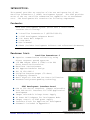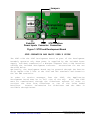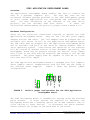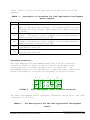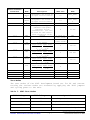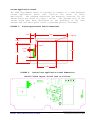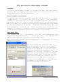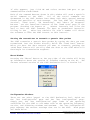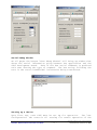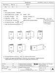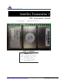
1
®
WIRELESS DATA SOLUTIONS THAT WORK®
Satellite Transmitter 2
STX2 Development System
Document
#9100-0142-01
Actual
USER’S MANUAL
AXONN L.L.C.
2021 Lakeshore Drive
New Orleans, LA 70122
504-282-8119
Fax: 504-282-0999
www.axonn.com
Specifications and design are subject to change without notice
A X O NN WIRELESS DATA SOLUTIONS THAT WORK®
- 1 -
#9100-0XXX-01 Version 1.0 0705
INTRODUCTION:
This manual provides an overview of the use and operation of the
Satellite Transmitter 2 (STX2) Development System. The STX2 provides
state of the art satellite communication capabilities at narrowband
cost. The Development Kit contains the following components:
Contents:
Each STX2 Development System (Sales Part # 1800-0104-01)
contains the following:
1 Satellite Transmitter 2 (#2100-0199-01)
1 STX2 Development Adapters Board
1 DC Power Wall Adapter
1 USB Cable
User’s Manual
CDROM (includes Development Software and referenced documents)
Features List:
Satellite Transmitter 2
Superior communication reliability using
direct sequence spread spectrum
+18 dBm Output Power @ 100b/s with FEC
Error Detection/Correction
Excellent Jam Resistance
FCC Approved Modular Design
FCC ID L2V-STX2-1
Stripline Antenna Output (50 Ohms)
4 Frequency Channels
Small Physical Size And Low Power Utilization
Patented and patent-pending technology
STX2 Development Interface Board
USB or TTL Serial interface (jumper selectable)
True USB Serial interface for STX2 Application
Development
Jumper Selectable Voltage Power Supply
DC Power Wall Adapter for Development Mode
Jumper control of STX2 power supply
Interface block for Application Development
Schematic included in Appendix C
Specifications and design are subject to change without notice
A X O NN WIRELESS DATA SOLUTIONS THAT WORK®
- 2 -
#9100-0142-01 Version 1.0 0804
Jumpers
STX2
Development Antenna
Area
External
USB STX2 Interface
Power Inputs Connector Connection
Figure 1: STX2 and Development Board
STX2 OPERATION AND BASIC USER’S GUIDE
The STX2 with the STX2 Development Board as part of the Development
Assembly operates only when power is supplied by the included Power
Supply and when connected to a Windows computer with a USB interface
running the included development software. Instructions for use are
detailed below.
Optionally, the Development Board may be powered through the barrier
strip inputs with 3.3VDC to the VDIG and VRF terminals and Ground to
the two GND terminals.
In order to receive messages from the STX2, the Application
Development Board must be in full view of the sky.
Also, the STX2
must be commissioned through the Globalstar network in order to
receiver the data from Globalstar or one of the Value Added
Resellers.
Contact information for Globalstar and the VARs is
available through Axonn.
Specifications and design are subject to change without notice
A X O NN WIRELESS DATA SOLUTIONS THAT WORK®
- 3 -
#9100-0142-01 Version 1.0 0804
Overview:
STX2 APPLICATION DEVELOPMENT BOARD
The Application Development Board enables the user to connect the
STX2 to a personal computer (PC).
The user may then use the
evaluation software package provided in the STX2 Development System
or write custom applications for configuring and controlling the
STX2.
For more information on the features of the STX2 serial
protocol, see the included STX2 Data Sheet.
If there are
difficulties understanding the protocol, please contact Axonn L.L.C.
Hardware Configuration:
There are two electrical connections required to operate the STX2
Application Development Board.
They are the 110V wall power supply
adapter and the USB cable. The 110V adapter must be plugged into an
available wall outlet as well as the Application Development Board.
The USB cable must be plugged into the Application Development Board
and an available USB port on the users PC running Windows 2000 or
later operating system.
Installation and operation of the software
will be covered in another section of this document. Optionally, the
Development Board may be powered through the barrier strip inputs
with 3.3VDC to the VDIG and VRF terminals and Ground to the two GND
terminals.
The power supply must be capable of 1000 mA at 3.3VDC
with less than 50 mV ripple.
The STX2 Application Development Board is equipped with five jumpers.
These jumpers control communications with the STX2 and the setup of
the on-board power supplies.
Figure 2 shows the default jumper
configurations.
JP4
FIGURE 2:
VDIG EN
TEST2
JP1
TEST1
USB EVAL
JP3
JP2
VRF EN
JP5
Default jumper configuration for the STX2 Application
Development Board
The STX2 Development Board is intended for testing using the attached
patch antenna.
If other options are required for antennas, the
Development Board has a mounting option for an SMA connector (J4) to
allow cabling to other devices.
To disconnect the patch antenna,
remove resistor R8 (0 Ohm) on the back side of the board.
Specifications and design are subject to change without notice
A X O NN WIRELESS DATA SOLUTIONS THAT WORK®
- 4 -
#9100-0142-01 Version 1.0 0804
Table 1 below, gives a brief description of the function of the
jumpers.
TABLE 1:
JUMPER
JP1
JP2
JP3
JP4
JP5
Description of operation for STX2 Application Development
Board Jumpers.
DESCRITPION OF OPERATION
Switches the STX2 communications between either the USB
port or the Evaluation Header. If communicating via the
Evaluation 14 pin header then change the jumper setting
to EVAL.
Connects the on-board 3.3V regulator to the STX2 VDIG
input. Disconnect (remove jumper) if providing external
power through terminal block TB1.
Connects the on-board 3.3V regulator to the STX2 VRF
input. Disconnect (remove jumper) if providing external
power through terminal block TB2.
TEST jumper for RF test measurements. Use in
conjunction with JP5
TEST jumper for RF test measurements. Use in
conjunction with JP5
Interface Connector:
The STX2 Application Development Board has a 14 pin connector
interface, shown in Figure 3 below, used for development and
interconnection of custom hardware onto the AXTracker. The
Development Board is also designed to accept the users custom host
board with mounting locations as diagramed in Figure 4 below.
J5
FIGURE 3:
J3
J7
J6
1
1
5
3
1
4
3
2
2
6
4
2
2
1
STX2 Development Board Interface Connector
The STX2 Development Board Interface connectors match up to the STX2
connectors as follows:
TABLE 2:
Pin Descriptions for the STX2 Application Development
Board.
Specifications and design are subject to change without notice
A X O NN WIRELESS DATA SOLUTIONS THAT WORK®
- 5 -
#9100-0142-01 Version 1.0 0804
STX2 Development
Board Interface
Connectors
J5-1
J5-2
J3-1
J3-2
Name
TEST
INPUT
1
TEST
INPUT
2
RESET
OC OUT
Description
STX2 Pins
Name
Designed to be driven by
an open collector/drain.
12
TEST INPUT
1
Designed to be driven by
an open collector/drain.
13
TEST INPUT
2
9
RESET
8
OC OUT
3 14 15 17
19-21 23-46
3 14 15 17
19-21 23-46
GND
5
STU TX
4
STU RTS
7
STU TX
J7-1
GND
STX2 Reset
Designed to trigger an
external high power
regulator for RF
transmission. Can also
be used for LED Control.
Limit current to 10 mA.
Ground
J7-2
GND
Ground
J7-3
TX
SETUP
3.3V Levels
Logic Level Input Level
0
<
0.8V
1
>
2.4V
3.3V Levels
Logic Level Input Level
0
<
0.8V
1
>
2.4V
3.3V Levels
Logic Level Input Level
0
<
0.8V
1
>
2.4V
3.3V Levels
Logic Level Input Level
0
<
0.8V
1
>
2.4V
Eval Board 3.3VDC Input
Low Power 3.3V DC Input
High Power 3.3V DC Input
J7-4
SETUP
INT
J7-5
RX
SETUP
J7-6
EVAL
CTS
J6-1
J6-2
J6-3
J6-4
VIN
VDIG
VRF
N/C
GND
STU CTS
6
---2
16 18
No connect
No connect
VDIG
VRF
Test Modes
The test modes of the STX2 Development Board are for RF and current
testing the various modes are accessed by applying the TEST jumpers
and cycling power to the unit.
Table 3: STX2 Test Modes
TEST 1 Jumper
TEST 2 Jumper
Operation
Off
Off
Normal Operation
On
Off
Single Test Packet
Off
On
30 second CW Signal
On
On
30 second modulated signal
Specifications and design are subject to change without notice
A X O NN WIRELESS DATA SOLUTIONS THAT WORK®
- 6 -
#9100-0142-01 Version 1.0 0804
Custom Application Board:
The STX2 Development Board is intended to connect to a used designed
custom
application
board
that
fulfills
the
needs
of
their
application.
The maximum dimensions and mounting locations for the
custom board are shown in Figure 3 below.
The maximum area of the
custom board have been determined by the proximity of the STX2
antenna and available space inside a pre-made plastic enclosure.
FIGURE 3:
Custom Application Board Dimensions
2.655
0.355
[email protected]
0.462
0.2100
0.1000
1.5850
TYP
1.571
0.310
1.5500
FIGURE 4:
Custom host application board dimensions
Overall board layout should look as follows:
TB1
TB2
5-9VDC
J6
J7
J3
J5
J1
J12
VRF
GND
VDIG
GND
C25
EVAL
USB
L2
C5
R33
JP1
R 34
R30
R35
Y1
U5
C 15
C 14
C41
R49
R5
C26
C27
R4
U8
U6
R2
R29
R32
2
R1
Q1
U4
3
C21
E1
R3
C22
R26
R31
C31
R37
R36
R27
LED1
4
U7
R41
1
C24
C23
R38
C29
C30
JP5
C13
TEST1
6
R40
5
TP1
TP2
C19
C 20
C28
R39
Z3
8
VDIG EN
R43
R44
9
JP3
C7
7
R42
U1
JP 4
C 12
J2
TEST2
C61
Z4
10
C6
D4
C60
VRF EN
JP2
L6
JP6
C36
U2
L1
C2
R6
D1
R7
R86
R10
C1
R9
C57
C58
R84
C59
J4
Specifications and design are subject to change without notice
A X O NN WIRELESS DATA SOLUTIONS THAT WORK®
- 7 -
#9100-0142-01 Version 1.0 0804
STX2 APPLICATION DEVELOPMENT SOFTWARE
Overview:
A software development CD-ROM is included in each STX2 Development
System.
The CD contains the STX2 Setup Tool executable as well as
device drivers for the USB interface.
Axonn Software Installation:
To operate the software programs they must be installed on a laptop
or desktop PC.
To Install the STX2 Setup Tool, first insert the
software CD (included with your STX2 Development System) into the CDROM drive of the PC. The CD should automatically run the installer,
but if it does not, simply run the program INSTALLER.EXE file found
at the root directory of the CD.
From the installer menu, you can
select/highlight which of the listed programs you would like to
install. To install a program, click on the desired program and then
click on the run button to begin the automatic installation.
STX2 Setup Tool:
STX2 Setup Tool is a comprehensive tool set for configuring and
controlling the transmitter.
There are only a few options for
controlling the STX2, which will be explained below.
When first starting the STX2 Evaluation Tool software the following
window will appear:
The first thing that should be done is
setting the COM port from the pulldown
window just under the “Get STU ID window.
If the wrong COM port is selected, there
can be no communications between the
computer and the STX2. Generally, the COM
port will be the highest number available
on the pulldown list, as the COM port was
just installed when the software was
installed and the USB cable plugged in.
If the incorrect COM port is selected and
a command is set to the STX2, the
following message will appear:
Specifications and design are subject to change without notice
A X O NN WIRELESS DATA SOLUTIONS THAT WORK®
- 8 -
#9100-0142-01 Version 1.0 0804
If this appears, just click OK and select another COM port to get
communications established.
Each of the command buttons shown in this window will send a specific
serial command to the STX2.
All of the serial commands are
documented in the STX2 Product Data Sheet with their general message
format and specifics of each message.
The “Get STX2 ID”, “Firmware
Version”, “Send Data”, “TX Remaining”, and “Abort TX Sequence”
buttons
are the functional buttons on the “Send Data” page of the
program. Checking the Repeat at __ Minute Intervals box allow the
user to have the STX2 transmit its data at predefined intervals.
Filling in the __ white box (default 10) with a number will direct
the software to have the STX2 transit at this interval.
Setting the transmitter to transmit a generic data packet
The STX2 transmits a generic data packet by typing the data you want
transmitted into the window directly below the “Send Data” button.
After you have the data entered you want to transmit, pushing the
:Send Data” button will serially send the data to the STX2 which will
then begin its transmission sequence.
About Window:
Pressing the “About” button at the top right of the window will bring
up information about the version of software running on the PC. The
current released version of the STX2 Evaluation Tool is Version 0.6
Configuration Windows:
There are two other ‘pages’ to the STX2 Evaluation Tool, which are
the “Set Configuration” page and the “Get Configuration” page.
Simply put, the “Set Configuration” page loads in the operating
conditions for the STX2 to run under such as the operating frequency,
retries, and dithering minimum and maximum. The “Get Configuration”
page requests the current settings that are in the STX2. Both pages
are shown below.
Specifications and design are subject to change without notice
A X O NN WIRELESS DATA SOLUTIONS THAT WORK®
- 9 -
#9100-0142-01 Version 1.0 0804
Serial Debug Window
On all pages the button “Show Debug Window” will bring up window that
shows the serial information going between the application and the
STX2 Development Board. Each of the hex serial commands is prefaced
with text showing the type of command. The hex string following the
text is the actual hexadecimal information being transferred.
Setting up a device
Upon first use, each STX2 must be set up for operation.
The “Set
Configuration” tab controls all setting for normal operation of the
Specifications and design are subject to change without notice
A X O NN WIRELESS DATA SOLUTIONS THAT WORK®
- 10 -
#9100-0142-01 Version 1.0 0804
STX2. The STX2 must be set up according the frequency and rate plans
established by Globalstar in your region of the world.
Please
contact your local Globalstar representative for details.
When the
correct settings are entered for your region, pressing the “Send
Setup” button will send the configuration to the STX2 and store it in
non-volatile memory so that it can use this information each time it
is powered up.
Status Message from a device
Once a device has been setup, pressing the “Get Setup” button on the
“Get Configuration” page will update the values in all of the boxes
to the right of each parameter.
These boxes indicate the actual
parameters that are loaded in the device.
FCC Compliance Statement:
The Satellite Transmitter 2 has been pre-approved for use in other
products under the Modular rules for the Federal Communications
Commission and Industry Canada.
Optionally the designer may opt to
test their final product to obtain their own FCC and IC ID’s.
All
products developed by user to include the STX2 may require additional
approvals by the FCC and/or IC prior to marketing or sale of such
products and user bears all responsibility for obtaining prior
approval.
For use in the United States, under the FCC rules, the device must
have on display in plain sight:
Contains FCC ID: L2VSTX2-1
For use in Canada, under Industry Canada rules, the device must have
on display in plain sight:
IC: 3989A-STX21
FCC Disclaimer:
The Development System is intended for use solely by professional
engineers for evaluating the feasibility of low-power wireless data
communications applications.
The manufacturer recommends that the
user’s evaluation be within a laboratory setting.
If user has obtained the Development System for any purpose not
identified above, including all conditions for assembly and use, user
should return the Development System to manufacturer immediately.
Specifications and design are subject to change without notice
A X O NN WIRELESS DATA SOLUTIONS THAT WORK®
- 11 -
#9100-0142-01 Version 1.0 0804
AXONN L.L.C
Copyright © 1999-2005 AXONN L.L.C. All rights reserved. Axonn, the
Axonn logo, and the statement Wireless Data Solutions That Work are
registered trademarks of Axonn L.L.C.
STX2 and AXTracker are
trademarks of Axonn L.L.C., which may be registered in some
jurisdictions.
All other brand or product names are trademarks of their respective
holders.
Specifications and design are subject to change without notice
A X O NN WIRELESS DATA SOLUTIONS THAT WORK®
- 12 -
#9100-0142-01 Version 1.0 0804