1
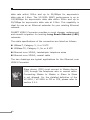
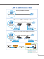
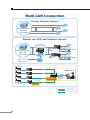
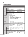
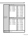
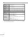
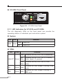
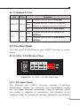
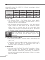
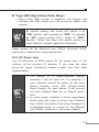
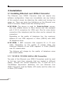
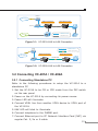
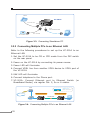
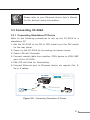
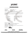
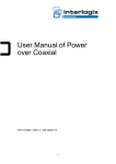
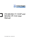
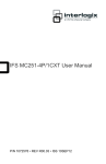
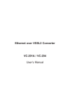
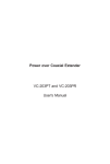
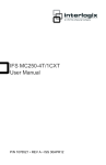
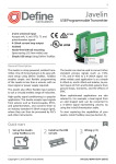
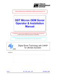
Ethernet over VDSL2 Converter VC-201A / VC-202A User’s Manual Trademarks Copyright © PLANET Technology Corp. 2014. Contents are subject to revision without prior notice. PLANET is a registered trademark of PLANET Technology Corp. All other trademarks belong to their respective owners. Disclaimer PLANET Technology does not warrant that the hardware will work properly in all environments and applications, and makes no warranty and representation, either implied or expressed, with respect to the quality, performance, merchantability, or fitness for a particular purpose. PLANET has made every effort to ensure that this User’s Manual is accurate; PLANET disclaims liability for any inaccuracies or omissions that may have occurred. Information in this User’s Manual is subject to change without notice and does not represent a commitment on the part of PLANET. PLANET assumes no responsibility for any inaccuracies that may be contained in this User’s Manual. PLANET makes no commitment to update or keep the current information in this User’s Manual, and reserves the right to make improvements to this User’s Manual and/or to the products described in this User’s Manual, at any time without notice. If you find information in this manual incorrect, misleading, or incomplete, we would appreciate your comments and suggestions. FCC Warning This equipment has been tested and found to comply with the limits for a Class A digital device, pursuant to Part 15 of the FCC Rules. These limits are designed to provide reasonable protection against harmful interference when the equipment is operated in a commercial environment. This equipment generates, uses, and can radiate radio frequency energy and, if not installed and used in accordance with the Instruction manual, may cause harmful interference to radio communications. Operation of this equipment in a residential area is likely to cause harmful interference in which case the user will be required to correct the interference at his own expense. CE Mark Warning This is a Class A product. In a domestic environment, this product may cause radio interference, in which case the user may be required to take adequate measures. Energy Saving Note of the Device This power operation. required device does not support Standby mode For energy saving, please remove the DC-plug or push the hardware Power Switch to OFF position to disconnect the device from the power circuit. Without removing the DC-plug or switch off the device, the device will still consume power from the power source. In the view of Saving the Energy and reduce the unnecessary power consuming, it is strongly suggested to power off or to remove the DC-plug for the device if this device is not intended to be active. WEEE Warning To avoid the potential effects on the environment and human health as a result of the presence of hazardous substances in electrical and electronic equipment, end users of electrical and electronic equipment should understand the meaning of the crossed-out wheeled bin symbol. Do not dispose of WEEE as unsorted municipal waste; they should be collected separately. Revision Ethernet over VDSL2 Converter User's Manual For Models: VC-201A / VC-202A Rev 2.0 (April 2014) Part No.: 2350-AC0270-002 Table of Contents 1.Introduction...................................................................... 5 1.1Checklist.................................................................... 5 1.2 Ethernet over VDSL2 Bridge Description........................ 5 1.3 Key Features............................................................... 9 1.4 Specifications............................................................ 10 2.Hardware Description....................................................... 13 2.1 Front Panel............................................................... 13 2.2 The Rear Panel......................................................... 15 3.Installation...................................................................... 18 3.1 Installing Ethernet over VDSL2 Converter.................... 18 3.2 Connecting VC-201A / VC-202A.................................. 19 3.3 Connecting VC-202A.................................................. 21 3.4 Chassis Installation and Rack Mounting (VC-201A and VC-202A)............................................ 22 4.Power Information........................................................... 24 5.Troubleshooting............................................................... 25 6.FAQs............................................................................... 26 1.Introduction 1.1Checklist Check the contents of your package for following parts: VC-201A / VC-202A x 1 5V DC/2A AC-to-DC Power Adapter x 1 RJ-11 Telephone Line x 1 (VC-201A only) User’s Manual x 1 If any of these items are missing or damaged, please contact your dealer immediately, if possible, retain the carton including the original packing material, and use them again to repack the product in case there is a need to return it to us for repair. 1.2Ethernet over VDSL2 Bridge Description PLANET's state-of-the-art Ethernet-over-VDSL2 products are based on two core networking technologies: Ethernet and VDSL2 (Very-high-data-rate Digital Subscriber Line 2). This technology offers the absolutely fastest possible data transmission speeds over existing copper telephone lines or coaxial cables without the need for rewiring. The VC-201A / VC-202A Ethernet Over VDSL2 Converter has a switching architecture with RJ-45 10/100Mbps Ethernet port and one asymmetric or symmetric Ethernet over VDSL port (Asymmetric means upstream and downstream rates are not the same while symmetric means upstream and downstream rates are similar) – the VDSL port can be RJ-11 connector (VC-201A) or BNC Connector (VC-202A). The VC-201A / VC-202A can be set to Central Office (CO) or Customer Premises Equipment (CPE) mode via a DIP switch. When VC-201A-CO is connected with the other VC-201A-CPE device, the performance will go up to 100/55Mbps for asymmetric 5 data rate within 200m and up to 25/4Mbps for asymmetric data rate at 1.6km. The VC-202A (BNC) performance is up to 100/65Mbps for asymmetric data rate within 200m and up to 25/5Mbps for asymmetric data rate at 3.0km. This capability is ideal for use as an Ethernet extender for your existing Ethernet network. PLANET VDSL2 Converter provides a much cheaper replacement and smooth migration for existing Long Reach Ethernet (LRE) networks. The cable specifications of the connection are listed as follows: 10Base-T, Category 3, 4 or 5 UTP 100Base-TX, Category 5, 5e or 6 UTP Ethernet over VDSL2, twisted-pair telephone wires Ethernet over VDSL2, coaxial cable The two drawings are typical applications for the Ethernet over VDSL2 Converter. Note 6 Slave device (CPE) must connect to Master device (CO) through the telephone wire or coaxial cable. Connecting Master to Master or Slave to Slave is not allowed. For the detailed definition of the VC-201A / VC-202A to CO or CPE, please refer to section 2.2.1. LAN to LAN Connection Existing Telephone Network Main office/PBX, Telco CO, wire closet Ethernet over VDSL and Telephone Network Up to 1.6km Main office/PBX, Telco CO, wire closet VC-201A/ CO VC-201A/ CPE LAN1 LAN2 Ethernet over VDSL and Telephone Network Up to 1.6km Main office/PBX, Telco CO, wire closet VC-204/ CO VC-204/ CPE LAN1 LAN2 VC-202A CPE IP Camera CAM Viewer VC-202A CO Coaxial Cable VDSL2 Up to 3.0km 100Base-TX UTP Telephone wire VDSL2 VDSL2 Coaxial Cable 7 Multi-LAN Connection Existing Telephone Network Main office/PBX, Telco CO, wire closet Ethernet over VDSL and Telephone Network VC-201A+ MC-700 Chassis Main office/PBX, Telco CO, wire closet Internet VC-201A/ CPE LAN1 VC-204/ CPE LAN2 Router IP Camera Coaxial VDSL2 CAM Viewer VDSL2 VDSL2 Coaxial IP Camera VC-202A CPE+ MC-700 Chassis Ethernet Switch VDSL2 VC-202A CO 100Base-TX UTP Telephone wire VDSL2 8 VDSL2 Coaxial Cable 1.3Key Features The Ethernet Over VDSL2 Converter provides the following key features: Cost-effective VDSL2 CO / CPE bridge solution One box design, CO / CPE selectable via DIP Switch Defines Asymmetric (Band Plan 998) and Symmetric band plans for the transmission of Upstream and Downstream signals Complies with IEEE 802.3, IEEE 802.3u and IEEE 802.3x standards DMT (Discrete Multi-Tone) line coding Half duplex back pressure and IEEE 802.3x full duplex pause frame flow control Built-in POTS splitter to share voice and data - (VC-201A) Voice and data communication can be shared on the existing telephone wire simultaneously - (VC-201A) Supports up to 1536 bytes packet size, 802.1Q VLAN tag transparent VDSL2 Stand-Alone transceiver for simple bridge modem application Selectable Target Band Plan and Target SNR Margin Supports extensive LED indicators for network diagnostics 9 1.4Specifications Product VC-201A VC-202A Hardware Specifications 1 x RJ-45, 10/100 Auto-negotiation Base-TX Auto-MDI/MDI-X Ports 1 x RJ-45, Auto-negotiation Auto-MDI/MDI-X VDSL 1 x RJ-11, female Phone Jack 1 x BNC, female connector PHONE 1 x RJ-11, Built-in splitters for POTS connection - DIP Switch 4 position DIP switch Functionality • CO / CPE mode select • Selectable fast and interleaved mode • Selectable target Band Plan • Selectable target SNR mode Encoding •VDSL-DMT - ITU-T G.993.1 VDSL - ITU-T G.997.1 - ITU-T G.993.2 VDSL2 (Profile 17a Support) LED Indicators One Power 3 for RJ-11/VDSL2 2 for RJ-45 10/100Base-TX port Cabling •10Base-T: 2-pair UTP Cat.3, 4, 5 up to 100m (328ft) Ethernet •100Base-TX: 2-pair UTP Cat.5, 5e, 6 up to 100m (328ft) VDSL 10 One Power 3 for RJ-11/VDSL2 2 for RJ-45 10/100Base-TX port Twisted-pair telephone 50 ohm, RG58A/U, wires (AWG24 or better) RG58C/U, RG58/U or 75 up to 1.6km ohm, RG6 (Distance 3.0km) Asymmetric Mode 200m -> 100/55Mbps 400m -> 90/50Mbps 600m -> 70/40Mbps 800m -> 60/25Mbps 1000m -> 45/15Mbps 1200m -> 35/10Mbps 1400m -> 30/6Mbps 1600m -> 25/4Mbps Performance* (Downstream / Upstream) Symmetric Mode 200m -> 100/100Mbps 400m -> 90/95Mbps 600m -> 70/70Mbps 800m -> 55/50Mbps 1000m -> 45/35Mbps 1200m -> 30/25Mbps 1400m -> 25/20Mbps 1600m -> 20/15Mbps Power Requirements 200m -> 100/65Mbps 400m -> 100/64Mbps 600m -> 100/59Mbps 800m -> 100/53Mbps 1000m -> 94/44Mbps 1200m -> 84/36Mbps 1400m -> 74/28Mbps 1600m -> 66/19Mbps 1800m -> 60/14Mbps 2000m -> 44/15Mbps 2200m -> 35/12Mbps 2400m -> 32/10Mbps 2600m -> 29/8Mbps 2800m -> 27/6Mbps 3000m -> 25/5Mbps 200m ->100/100Mbps 400m -> 97/100Mbps 600m -> 86/91Mbps 800m -> 79/80Mbps 1000m -> 69/66Mbps 1200m -> 60/52Mbps 1400m -> 51/41Mbps 1600m -> 45/36Mbps 1800m -> 40/29Mbps 2000m -> 27/26Mbps 2200m -> 23/24Mbps 2400m -> 22/21Mbps 2600m -> 20/18Mbps 2800m -> 18/15Mbps 3000m -> 17/13Mbps 5V DC, 2A 11 Operating Temperature 0~50 degrees C Storage Temperature -10~70 degrees C Operating Humidity 10% to 90%, relative humidity, non-condensing Storage Humidity 10% to 90%, relative humidity, non-condensing Standard Conformance Regulation Compliance FCC Part 15 Class A, CE Standards Compliance IEEE 802.3 10Base-T IEEE 802.3u 100Base-TX IEEE 802.3x Full Duplex Pause Frame Flow Control ITU-T •G.993.1 (VDSL) •G.997.1 •G.993.2 VDSL2 (Profile 17a) * The actual data rate will vary on the quality of the copper wire and environment factors. 12 2.Hardware Description VC-201A The VC-201A provides 2 RJ-11 ports for voice connection (like telephone) and for network line connection. VC-202A The VC-202A provides 1 BNC connector and supports 50 or 75 ohm cable with distance up to 3.0km. The VC-201A and VC-202A provide 1 RJ-45 port each with two different running speeds – 10Mbps and 100Mbps. It will distinguish the speed of incoming connection automatically. This section describes the hardware features of the Ethernet over VDSL2 Converter. For easier control of the converter, familiarize yourself with its display indicators and ports. Front panel illustrations in this chapter display the unit LED indicators. Before connecting any network device to the converter, read this chapter carefully. 2.1Front Panel The units’ front panel provides a simple interface monitoring the Ethernet over VDSL2 Converter. VC-201A Front Panel Figure 2-1: VC-201A Front Panel 13 VC-202A Front Panel Figure 2-2: VC-202A Front Panel 2.1.1 LED Indicators for VC-201A and VC-202A The rich diagnostic LEDs on the front panel can provide the operating status of individual port and whole system. System LED PWR Color Green Function Light Power ON. Off Power OFF. VDSL LED Color Function Light Fast LNK/ACT Green Blink Slow Blink Indicates that the VDSL link is established. Indicates that the VDSL link is in training status (about 10 seconds). Indicates that the VDSL link is in idle status. CO Green Light Indicates the VDSL Bridge is running in CO mode. CPE Green Light Indicates the VDSL Bridge is running in CPE mode. 14 10/100Base-TX Port LED Color Function Light LNK/ACT Green Blink 100 Indicates that the port is Link Up. Indicates that the Converter is actively sending or receiving data over that port. Off Indicates that the port is Link Down. Light Indicates that the port is operating at 100Mbps. Off Indicates that the port is Link Down or 10Mbps. Green 2.2The Rear Panel The rear panel of the Ethernet over VDSL2 Converter is shown below. VC-201A / VC-202A Rear Panel 1 2 3 4 ON Figure 2-3: VC-201A / VC-202A Rear Panel 2.2.1 DIP Switch Mode The Ethernet over VDSL2 Converter provides 4 selective transmission modes. By switching the transmission mode, you can obtain the best transmission mode to suit with phone line quality or distance of connectivity. The following is the summary table of transmission setting, bandwidth and distance 15 extensibility tested for AWG 24 (0.5mm) twisted-pair without noise and cross talk. DIP-1 DIP-2 DIP-3 DIP-4 Mode Channel Band Plan SNR OFF CO Interleave Symm 9dB ON (default) CPE Fast Asymm 6dB CO / CPE • CO (Central Office) – the Master device mode, usually the CO device will be located at the data center of ISP or enterprise to link to the backbone. • CPE (Customer Premises Equipment) – the Slave device mode, usually the CPE device will be located at branch office, home or remote side as the long reach data receiver. The CPE can be connected to the PC, IP Camera or Wireless Access Point and etc network devices. Note When the Ethernet Over VDSL2 Converter operates in CPE mode, the DIP switch 2,3,4 is not functional. Fast and Interleaved Mode • Fast mode guarantees a minimum end to end latency less than 1 ms. • Interleaved mode provides impulse noises protection with a duration less than 250 us. Interleaved mode has a maximum end to end latency of 10m sec. Band Plan • User can switch the Band Plan either Symmetric or Asymmetric by their own. Symmetric is selected to provide better upstream performance. Asymmetric is selected to provide better downstream performance. Refer to the table above for details. 16 Target SNR (Signal Noise Ratio) Margin • When fixed SNR margin is selected, the system will maintain the SNR margin at 9 dB across all usable loop lengths. Note By default setting, the fourth DIP switch is at “ON” position and operates as “CPE”. To operate as “CO”, please adjust DIP 1 switch to “OFF” position. Adjust the other DIP switch setting to meet different network application demands. Please power off the Ethernet over VDSL2 Converter before making any transmission mode adjustment. 2.2.2 DC Power Jack The VC-201A and VC-202A require 5V DC power input. It will conform to the bundled AC adapter. If you have the issue about the power connection, please contact your local sales representative. Note 1. The device is a power-required device, meaning it will not work till it is powered. If your networks should be active all the time, please consider using UPS (Uninterrupted Power Supply) for your device. It will prevent you from network data loss or network downtime. 2.In some areas, installing a surge suppression device may also help to protect your Ethernet Over VDSL2 Converter from being damaged by unregulated surge or current to the Ethernet over VDSL2 Converter or the power adapter. 17 3.Installation 3.1Installing Ethernet over VDSL2 Converter The Ethernet over VDSL2 Converter does not require any software configuration. Users can immediately use any feature of this product simply by attaching the cables and turning the power on. There are some key limitations on the Ethernet over VDSL2 Converter. Please check the following items: VC-201A: The device is used for Point-to-Point connection only (Master device to Slave device) and has equipped with 2 RJ-11 connectors for VDSL port. One for voice device connection (like telephone) and the other one for network link connection. Depending on the quality of telephone line, the maximum distance of one VDSL segment is 1.6km (6561ft) with AWG 24 telephone wires. VC-202A: 1 BNC connector that supports 50 or 75 ohm cable. Depending on the quality of coaxial cable, the maximum distance of one VDSL segment is 3.0km (9842ft) over 5C coaxial cable. The distance will change by the quality of telephone wires and coaxial cables. 3.1.1 VC-201A / VC-202A LAN to LAN Connection Two sets of the Ethernet over VDSL2 Converters could be used to link two local Area networks that are located in different places. Through the normal telephone line, it could set up a 100/55Mbps asymmetric backbone, but one Ethernet over VDSL2 Converter must be Master (CO mode) and the other one is Slave (CPE mode). 18 Router Internet VDSL2 CO Converter Switch VDSL2 CPE Converter Up to 1.6km 100Base-TX UTP PSTN Telephone wire PBX Phone Figure 3-1: VC-201A LAN to LAN Connection Router 100Base-TX UTP VDSL2 VDSL2 CO Converter Internet VDSL2 Coaxial Cable VDSL2 CPE Converter Coaxial Cable VDSL2 Switch Up to 3.0km Figure 3-2: VC-202A LAN to LAN Connection 3.2Connecting VC-201A / VC-202A 3.2.1 Connecting Standalone PC Refer to the following procedures to setup the VC-201A to a standalone PC. 1.Set the VC-201A to be CO or CPE mode from the DIP switch on the rear panel. 2.Power on the VC-201A by connecting its power source. 3.Power LED will illuminate. 4.Connect VDSL line from another VDSL device to VDSL port of the VC-201A. 5.LNK LED will blink to illuminate. 6.Connect telephone to the PHONE port. 7.Connect Ethernet port to PC Network Interface Card (NIC) via regular Cat. 5, 5e or 6 cable. 19 Phone VC-201A RJ-11 Line Cord Phone VDSL TP RJ-45 Cat.5 Twisted Pair Cable RJ-11 Line Cord RJ-11 Phone Jack Figure 3-3: Connecting Standalone PC 3.2.2 Connecting Multiple PCs to an Ethernet LAN Refer to the following procedures to set up the VC-201A to an Ethernet LAN. 1.Set the VC-201A to be CO or CPE mode from the DIP switch on the rear panel. 2.Power on the VC-201A by connecting its power source. 3.Power LED will illuminate. 4.Connect VDSL line from another VDSL device to VDSL port of the VC-201A. 5.LNK LED will illuminate. 6.Connect telephone to the Phone port. 7. VC-201A: Connect Ethernet port to Ethernet Switch (or Broadband Router) via regular Cat. 5, 5e or 6 cables. Router 100Base-TX UTP VDSL2 VDSL2 CO Converter Internet VDSL2 Coaxial Cable VDSL2 CPE Converter Coaxial Cable VDSL2 Switch Up to 2.0km Figure 3-4: Connecting Multiple PCs to an Ethernet LAN 20 Note Please refer to your Ethernet device User’s Manual for the device’s setup information. 3.3Connecting VC-202A 3.3.1 Connecting Standalone IP Device Refer to the following procedures to set up the VC-202A to a standalone PC. 1.Set the VC-202A to be CO or CPE mode from the DIP switch on the rear panel. 2.Power on the VC-202A by connecting its power source. 3.Power LED will illuminate. 4.Connect coaxial cable from another VDSL device to VDSL BNC port of the VC-202A. 5.LNK LED will blink for illuminating. 6.Connect Ethernet port to Ethernet device via regular Cat. 5, 5e or 6 cables. VC-202A 100Base-TX UTP VDSL2 BNC VDSL2 RG58 Jack VDSL2 Coaxial Cable VDSL TP RJ-45 Cat.5 Twisted Pair Cable RG58 / RG6 IP Camera Figure 3-5: Connecting Standalone IP Device 21 3.3.2 Connecting Multiple PCs to an Ethernet LAN 1.Set the VC-202A to be CO or CPE mode from the DIP switch on the rear panel. 2.Power on the VC-202A by connecting its power source. 3.Power LED will illuminate. 4.Connect coaxial cable from another VDSL device to VDSL BNC port of the VC-202A. 5.LNK LED will illuminate. 6. Connect Ethernet port to Ethernet Switch (or Broadband Router) via regular Cat. 5, 5e or 6 cables. VC-202A 100Base-TX UTP VDSL2 Coaxial Cable VDSL2 BNC VDSL b/g TP b/g RJ-45 Cat.5 Twisted Pair Cable VDSL2 RG58 Jack RG58 / RG6 Fast Ethernet Switch Figure 3-6: Connecting Multiple PCs to an Ethernet LAN Note Please refer to your Ethernet device User’s Manual for the device’s setup information. 3.4Chassis Installation and Rack Mounting (VC-201A and VC-202A) To install the Ethernet over VDSL2 Converter in a 10-inch or 19-inch Converter Chassis with standard rack, follow the instructions described below. 22 Step 1: Place your VC-201A / VC-202A on a hard flat surface, with the front panel positioned towards your front side. Step 2: Carefully slide in the module until it is fully and firmly fitted into the slot of the converter chassis. Figure 3-7: Insert a VDSL2 Converter Into an Available Slot Step 3: Attach a rack-mount bracket to each side of the Converter Chassis with supplied screws attached to the package. Step 4: After the brackets are attached to the Converter Chassis, use suitable screws to securely attach the brackets to the rack. Step 5: Proceed with Step 4 and Step 5 of the session 3.2 Stand-alone Installation to connect the network cabling and supply power to your Converter Chassis. Caution You must use the screws supplied with the mounting brackets. Damage caused to the parts by using incorrect screws would invalidate your warranty. 23 4.Power Information The power jack of the VC-201A / VC-202A is with 2.5mm in the central post and required +5V DC power input. It conforms to the bundled AC-DC adapter and Planet’s Media Chassis. If you encounter the issue about the power connection, please contact your local sales representative. Please keep the AC-DC adapter as a spare part when your VC-201A / VC-202A is installed in a Media Chassis. 2.5mm DC Receptacle 2.5mm +5V for each slot Media Chassis DC receptacle is 2.5mm wide which conforms to and matches the VDSL2 Converter 2.5mm DC jack's central post. Do not install any improper devices in Media Chassis. 24 5.Troubleshooting SYMPTOM: VDSL LNK LED does not light up after wire is connected to the VDSL port. CHECKPOINT: 1.Verify the length of the wire connected between two VC-201A / VC-202A is not more than 2km. Please also try to adjust the DIP switch of the VC-201A / VC-202A to the other SNR mode. 2.Please note you must use one VC-201A / VC-202A in CO mode and the other VC-201A / VC-202A in CPE mode. Connect to each other to make it work. SYMPTOM: TP LED does not light up after cable is connected to the port. CHECKPOINT: 1.Verify you are using the Cat.5, 5e or 6 cables with RJ-45 connector connected to the port. 2. If your device (like LAN card) supports auto-negotiation, please try to modify at a fixed speed of your device manually. 3. Check whether the converter and the connected device’s power are ON or OFF. 4.Check whether the port’s cable is firmly seated in its connectors in the switch and in the associated device. 5.Check whether the connecting cable is good. 6.Check whether the power adapters are functional, including the connecting device. 25 6.FAQs Q1: What voltage do the VC-201A and VC-202A use? A1: 5V DC, 2A Q2: What is VDSL2? A2:VDSL2 (Very High-Bit-Rate Digital Subscriber Line 2), G.993.2 is the newest and most advanced standard of xDSL broadband wire line communications. Designed to support the wide deployment of Triple Play services such as voice, data, high definition television (HDTV) and interactive gaming, VDSL2 enables operators and carrier to gradually, flexibly, and cost-efficiently upgrade the exiting xDSL-infrastructure. Q3: What is the best distance for the VC-201A and VC-202A? A3: In order to guarantee the stability and better quality of network, so we would suggest the distance within 1.6 kilometer is the best for the VC-201A and 3.0 kilometer for the VC-202A. Q4: What are the best data rates for the VC-201A and VC-202A? A4: The data rates of the VC-201A and VC-202A are up to 100Mbps/55Mbps and up to 100Mbps/65Mbps (downstream / upstream) in 200 meters, respectively. Q5: Is the VC-201 compatible with the VC-201A? A5: Currently no. Although the VC-201 (profile 12a) and the VC-201A (profile 17a) are based on ITU-T G.993.2 VDSL2, but with different profiles, so far, they are not compatible with each other. 26 Q6: Is the VC-202 compatible with the VC-202A? A6: Currently no. Although the VC-202 (profile 12a) and the VC-202A (profile 17a) are based on ITU-T G.993.2 VDSL2, but with different profiles, so far, they are not compatible with each other. Q7: What is SNR and what’s the effect? A7:In analog and digital communications, Signal-to-Noise Ratio, often written as SNR, is a measure of signal strength relative to background noise. The ratio is usually measured in decibels (dB). In digital communications, the SNR will probably cause a reduction in data speed because of frequent errors that require the source (transmitting) computer or terminal to resend some packets of data. SNR measures the quality of a transmission channel over a network channel. The greater the ratio, the easier it is to identify and subsequently isolate and eliminate the source of noise. Generally speaking, the higher SNR value gets better line quality, but lower performance. Q8: What is band plan and what’s the effect? A8: VDSL2 defines multiple band plans and configuration modes (profiles) to allow asymmetric and symmetric services in the same binder (by designated frequency bands) for the transmission of upstream and downstream signals. User has the ability to select fixed band plan. Symmetric is selected to provide better downstream performance while asymmetric is selected to provide better upstream performance. 27 EC Declaration of Conformity For the following equipment: *Type of Product *Model Number * Produced by: Manufacturer’s Name Manufacturer’s Address : : Ethernet over VDSL2 Converter VC-201A / VC-202A : Planet Technology Corp. : 10F., No.96, Minquan Rd., Xindian Dist. New Taipei City 231, Taiwan (R.O.C.). is herewith confirmed to comply with the requirements set out in the Council Directive on the Approximation of the Laws of the Member States relating to Electromagnetic Compatibility (2004/108/EC). For the evaluation regarding the Electromagnetic Compatibility, the following standards were applied: EN 55022 EN 61000-3-2 EN 61000-3-3 EN 55024 EN 61000-4-2 EN 61000-4-3 EN 61000-4-4 EN 61000-4-5 EN 61000-4-6 EN 61000-4-8 EN 61000-4-11 (2010) (2006+A1:2009+A2:2009) (2008) (1998 + A1:2001 + A2: 2003) (2009) (2006+A2:2010) (2004+A1:2010) (2006) (2009) (2010) (2004) Responsible for marking this declaration if the: Manufacturer Authorized representative established within the EU Authorized representative established within the EU (if applicable): Company Name: Planet Technology Corp. Company Address: 10F., No.96, Minquan Rd., Xindian Dist., New Taipei City 231, Taiwan (R.O.C.) Person responsible for making this declaration Name, Surname Kent Kang Position / Title : Product Manager Taiwan Place 16th Dec., 2013 Date Legal Signature PLANET TECHNOLOGY CORPORATION e-mail: [email protected] http://www.planet.com.tw 10F., No.96, Minquan Rd., Xindian Dist., New Taipei City, Taiwan, R.O.C. Tel:886-2-2219-9518 Fax:886-2-2219-9528