1
J002-872.1
Scanning Unit
OD000422.0.0
Scanning Unit J002-872.1
PRODUCT MANUAL
1
ABOUT THE MANUAL
2
SAFETY
3
TECHNICAL SPECIFICATION
4
IMPLEMENTATION
5
OPERATION
6
MAINTENANCE
7
TROUBLESHOOTING
8
APPENDICES
© JOT Automation Ltd.
All trademarks used are the property of JOT Automation Ltd. or its affiliates. All rights reserved. No part of this document may be reproduced in any form or by any
means without the prior written permission of JOT Automation Ltd. JOT Automation Ltd. retains ownership and intellectual property rights in drawings, models,
dimensions, shapes, solutions and ideas presented or expressed in this document.
Scanning Unit J002-872.1
1
ABOUT THE MANUAL
1.1
TYPOGRAPHIC CONVENTIONS ............................................................................ 2
1.2
ABBREVIATIONS .................................................................................................... 2
1.3
CONTACT INFORMATION ...................................................................................... 2
J002-872_1-01C_1_0_0.doc
1 About the manual | 1
Scanning Unit J002-872.1
1
ABOUT THE MANUAL
This document is principally intended for guidance to ordinary users of the
machine. The purpose of this document is to give a general description of the
machines operation and instructions on how to use it correctly and safely; it does
not contain any detailed information about the operation or electrical connections.
Further information is available in the machines technical documentation and
from the manufacturer.
The information described herein is subject to change without notice. The manual
has been checked for both reliability and accuracy. However, if you have any
questions, or notice any errors or omissions in this manual, please contact the
Field Service of JOT Automation.
1.1
TYPOGRAPHIC CONVENTIONS
The following typographical conventions are used to point out potential hazards
and other important issues:
Warning
Text notifies the reader of circumstances, which may cause personal injury.
Caution
Text notifies the reader of circumstances, which may cause serious damage on the device.
Note
Text is used to stress issues of special importance.
1.2
1.3
ABBREVIATIONS
DUT
Device Under Test
PWB
Printed Wire Board (same as PCB)
PCB
Printed Circuit Board (same as PWB)
RoHS
Restriction of Hazardous Substances
UDP
User Datagram Protocol
CONTACT INFORMATION
JOT Automation Ltd.
Vihikari 10
FI-90440 KEMPELE
FINLAND
Phone: +358 10 301 5000
Fax: +358 8 344 425
www.jotautomation.com
1 About the manual | 2
Scanning Unit J002-872.1
2
SAFETY
2.1
GENERAL SAFETY INSTRUCTIONS ..................................................................... 2
2.2
DANGEROUS ELEMENTS AND ISSUES ............................................................... 4
2.3
SAFETY DEVICES ................................................................................................... 4
2.4
SYMBOLS AND LABELS ........................................................................................ 5
J002-872_1-02C_1_0_0.doc
2 Safety | 1
Scanning Unit J002-872.1
2
SAFETY
This product consists of several modules and components. The manufacturing
process includes functions that may induce mechanical hazards, electrical
hazards, and other hazards that may form as a combination of the mentioned
hazards. These hazards may result in death, severe injury or product damage.
However, the hazards mentioned in the list above are located behind the
protective doors. Opening the doors will immediately stop operations and cut
power from hazardous objects and mechanisms. Therefore it is utterly important
to keep the machinery in its original condition and functionality.
Warning
Any modifications to the machine or software are forbidden without permission from the
manufacturer.
Unauthorized modifications or even temporary alterations to the machine or its
functioning may affect the user safety and will cancel manufacturer’s liability for
the product.
Safety of machinery is in conformity with the regulations of the European
Directives as indicated on the Declaration of Conformity signed for the machinery
in question. Safety standards, which have been applied to the safety functions,
are also stated on the Declaration of Conformity.
Note
Use of any controls, adjustments or performance of procedures other than those specified
herein may result in hazardous situations with the machinery.
2.1
GENERAL SAFETY INSTRUCTIONS
This chapter includes general safety instructions for personnel operating the
Scanning Unit. Read these instructions before performing any operations on the
machine.
Note
The machine may only be used by a person who is qualified to operate it and knows the safety
issues involved in operating it.
Do not wear loose or hanging clothes, tie or jewellery. Keep long hair
bound.
Perform operations according to instructions of this manual and all the
manuals enclosed for the components included in the machine.
When personnel, material or machine is in danger, stop the unit
immediately by pressing the Emergency stop button.
Do not place containers holding fluids such as coffee or soft drinks on
the machine.
2 Safety | 2
Scanning Unit J002-872.1
Do not direct a strong spray of fluid at the machine. If a spray of fluid is
directed at the machine, turn the mains off immediately and unplug the
power cord. Do not touch the machine due to a risk of electric shock.
Do not place heavy objects against or on top of the machine as they
may distort the operation. In case of a visible change in the machines
shape, turn the mains off immediately and unplug the power cord. Do
not touch the machine due to a risk of electric shock.
If the machine is displaced, e.g. due to an external force, check the
condition of the power cord. A damaged cord may cause an electric
shock.
When the machine is in operation, do not penetrate the manipulator's
workspace.
Do not stare into laser beam.
Perform teaching operations when operators are outside the
manipulator's workspace. If it is impossible to perform teaching
operation without penetrating the manipulator's workspace, be prepared
to press the Emergency stop button in case of unpredictable erroneous
motion or operation.
Note
Only personnel with special training may perform operations, such as teaching points for
robots.
Carry out inspections when the machine is out of operation. If it is
impossible to carry out inspection when the machine is out of operation,
keep outside the manipulator’s workspace.
Do not use the machine if it develops a fault or its safety devices are
damaged.
Do not make any modifications for electrics or mechanics of the
machine.
Do not make any modifications for the safety equipment.
2 Safety | 3
Scanning Unit J002-872.1
2.2
DANGEROUS ELEMENTS AND ISSUES
During operation and maintenance procedures pay special attention to the
following issues which may cause danger despite the safety equipment:
Robot; movements, impact energy
Conveyors; grabbing
Electric devices in general; risk of electrical shock
Laser devices and sensors; laser radiation, risk of eye injury
Vacuum system; mechanical risk
Pneumatic system; movements, impact energy
The machine includes a class 2 laser device which is classified as safe.
However, staring intensively into laser beam may lead into eye injury.
Study carefully safety instructions for concerning issues mentioned above.
2.3
SAFETY DEVICES
The machine is equipped with:
An emergency stop button, located on the membrane terminal. The
button is red and it is mounted on a yellow base.
Safety limit switches in all the hatches.
Pressing the emergency stop button stops the operation of all the machines in
Tiny line. Opening a hatch stops the operation of the machine and adjacent
machines in Tiny line. Press the emergency stop button if personnel or machine
is in danger.
Warning
Never bypass the safety devices or use the machine if the safety devices are damaged.
2 Safety | 4
Scanning Unit J002-872.1
2.4
SYMBOLS AND LABELS
The following symbols and labels indicate potential hazards when operating the
machine.
Label
Description
Hazardous voltage.
Contact will cause hazardous shock or
burn
Turn off and lock out power before
servicing.
Only authorized personnel may service
this machine.
See manual for safety information.
Read out and understand user manual
before operating this machine.
Failure to follow operating instructions
could result in injury or damage to the
equipment.
2 Safety | 5
Scanning Unit J002-872.1
3
3.1
TECHICAL SPECIFICATION
GENERIC TECHNICAL DATA ................................................................................. 2
3.1.1
Mechanics .................................................................................................. 3
3.2
TECHNICAL SPECIFICATION TABLE ................................................................... 4
3.3
PRODUCTS TO BE HANDLED ............................................................................... 4
3.4
RATING PLATE........................................................................................................ 5
3.5
FUNCTIONAL DESCRIPTION ................................................................................. 6
3.5.1
Operation .................................................................................................... 6
3.5.2
Axes ............................................................................................................ 6
J002-872_1-03C_1_0_0.doc
3 Technical specification | 1
Scanning Unit J002-872.1
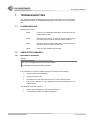
3
TECHNICAL SPECIFICATION
This chapter provides technical information about the machine.
3.1
GENERIC TECHNICAL DATA
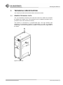
The JOT Automation Scanning Unit reads 2D-codes from PWBs and forwards
the PWBs to the master Tiny. It is intended for use in conditions prevalent only in
production lines of the electronics industry.
The machine is controlled by a programmable logic. The logic interface with
upstream and downstream devices is implemented via UDP and SMEMA
handshaking. The control equipment is located on the panel in the upper part of
the frame.
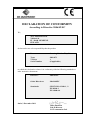
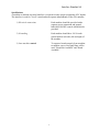
Figure 3.1-1 Main view
3 Technical specification | 2
Scanning Unit J002-872.1
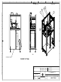
Figure 3.1-2 Dimensions
3.1.1
MECHANICS
The device consists of
Steel and aluminum profile construction
Linear motor robot axes (X-Y)
Conveyor
Return conveyor
Industrial PC
Graphical user interface
The whole system is CE and cUL approved.
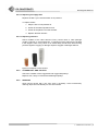
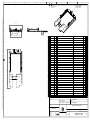
① Frame
② XY-axes and
conveyor
③ Return conveyor
Figure 3.1-3 Main parts
3 Technical specification | 3
Scanning Unit J002-872.1
3.2
TECHNICAL SPECIFICATION TABLE
Scanning Unit J002-872.1
Dimensions
Width
498 mm
Depth
800 mm
Height
1500 mm
Weight
118 kg
Handshaking
According SMEMA standard
Electrics
Supply Voltage
110/230 VAC (60/50 Hz)
Power consumption
160 W
Pneumatics
Supply Pressure
0.6 MPa
Other requirements
Clean, filtered air
Air consumption
1 l/min
Noise level at the workstation
Lower than 70 dB(A)
Sound pressure level (LAeq, 15 min)
Surroundings
Ambient Temperature
<+30 ºC
*Noise level is measured at the working place when the machine is in operation according
standard EN ISO 11201
3.3
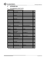
PRODUCTS TO BE HANDLED
The machine is capable of handling PWBs as described below.
Length up to, mm (")
Width up to, mm (")
Thickness, mm ("), flat belt
Thickness, mm ("), round belt
Carrying edge, mm (")
Weight, kg (lb)
Component height
Lower max. mm (")
Upper max. mm (")
300 (11.8)
150 (5.9)
1.0-3.0 (0.04-0.12)
0.5-3.0 (0.02-0.12)
3.0 (0.12)
max. 2.0 (4.4)
15 (0.6)
15 (0.6)
3 Technical specification | 4
Scanning Unit J002-872.1
3.4
RATING PLATE
Rating plate is situated either on the backside of the machine, near the lower
right corner.
The rating plate contains following information:
Manufacturer and contact information
Date (Date)
Project number (No)
Product code and name (Product)
Serial number (S.No)
CE logo
RoHS logo
Date of production (yyyy/mm/dd)
Supply pressure (bar)
Air consumption (l/min)
Operating voltage (V)
Operating frequency (Hz)
Current consumption (A)
Power consumption (kVA)
Weight (kg)
CE logo
RoHS 15 logo
WEEE logo
Figure 3.4-1 Rating plate
3 Technical specification | 5
Scanning Unit J002-872.1
3.5
FUNCTIONAL DESCRIPTION
Operation of the machine is engaged by UDP and SMEMA handshakings with
adjoining machines.
3.5.1
OPERATION
An idle scanning unit requests for a PWB. A sensor at the infeed edge detects
arriving PWB and it is conveyed to the predefined location. The machine checks
position and orientation of each PWB by laser measurement sensor. First it
scans the control points; height of a component in predefined point and a hole in
the PWB in predefined point.
If the PWB is incorrect or incorrectly placed, the control points cannot be found
and the operation of the machine stops with an alarm. The PWB can be removed
when the machine is in service mode. Before feeding in a new PWB, the
incorrectly placed / incorrect PWB has to be removed, service mode switched off,
and error checked on touch screen.
After the control points are successfully found, the scanning unit reads PWBs
2D-code with a camera. After the code reading is carried out, the unit signals that
the PWB can be forwarded and a new PWB can be received.
Finally the PWB is forwarded to the master Tiny Unit, which forwards PWBs to
next available Tiny or directly to Fail Marker Unit.
An error or a malfunction is indicated by the beacon and the buzzer. Cause of the
error is shown on the touch screen. Refer to chapter 7 Troubleshooting.
3.5.2
AXES
The conveyor conveys PWBs in X-axis direction. The camera and the laser
sensor move along XY-axes. XY-location is programmed in the GUI.
3 Technical specification | 6
Scanning Unit J002-872.1
4
IMPLEMENTATION
4.1
ACCEPTING DELIVERY .......................................................................................... 2
4.2
UNPACKING ............................................................................................................ 2
4.3
REQUIRED FLOOR SPACE .................................................................................... 2
4.4
INSTALLING MECHANICS ...................................................................................... 2
4.5
ELECTRIFICATION .................................................................................................. 3
4.6
CONNECTING PNEUMATICS ................................................................................. 4
4.7
CONNECTING CONTROL SYSTEM ....................................................................... 4
4.8
ADJUSTMENTS AND CALIBRATION .................................................................... 4
4.9
THE FIRST START-UP ............................................................................................ 4
4.10 WITHDRAWAL FROM USE AND STORAGE ......................................................... 5
4.10.1 Temporary storage .................................................................................... 5
4.10.2 Long-term storage and transportation .................................................... 5
4.10.3 Permanent withdrawal from use .............................................................. 5
J002-872_1-04C_1_0_0.doc
4 Implementation | 1
Scanning Unit J002-872.1
4
IMPLEMENTATION
This chapter includes instructions for installation and mechanical adjustment.
4.1
ACCEPTING DELIVERY
Before signing the bill of freight, inspect
The packages for visual defects.
All shock- and tilt watches and make sure they are not reacted.
Write down all defects to the bill of freight and take descriptive pictures.
Inform the defects to JOT Automation.
4.2
UNPACKING
Move the package carefully and lift it only from the indicated places. Pay
attention to transportation and handling instructions marked on the package.
Unpack the machine very carefully. Pay attention not to accidentally damage any
sensitive components, change factory settings or damage the surface finishing.
Use extreme care when lifting the machine from the shipping platform. The
machines center of gravity may not be at the expected location. Make sure no
cables, etc. are pinched between the machine and the forks of the forklift.
If the machine has been brought in from cold surroundings, allow the
temperature of the machine to stabilize for hours before unpacking the machine.
Note
The machines center of gravity may not be at the expected location. Use extreme care when
lifting the machine.
Caution
If the machine has been damaged during shipment, it is forbidden to use it prior to checking the
faults.
4.3
REQUIRED FLOOR SPACE
When installing the machine, leave enough free space for maintenance,
operating and moving around.
4.4
INSTALLING MECHANICS
This phase of the installation must be done extremely carefully because it has a
major effect on the machines operational reliability.
The machine must be installed at the factory according to the instructions given
by the person responsible for installation.
4 Implementation | 2
Scanning Unit J002-872.1
Installation instructions:
Reinstall the auxiliary equipments, which were removed for shipping.
Level the machine in both directions and adjust the height indicated in
the layout drawings by means of the adjustable legs and a bubble tube.
Fasten the machine mechanically to the surrounding units. Make sure
to fasten the machine so that it will not move even if it is pushed lightly.
Install the safety devices.
Check the functioning of the safety devices with the person responsible
for safety at work.
Ensure that there are no obstructions to product travel at the interface
to adjoining machines.
Check the installation by moving a product along the conveyor
manually.
Note
The final check of the installation will take place during the test run / start-up.
If adjacent machine is not a JOT product, place a safety cover in front of the
conveyor openings of the machine.
If a single JOT product has been ordered to the production line, JOT Automation
is not responsible for the safety around the machine.
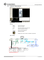
4.5
ELECTRIFICATION
Caution
If the machine is delivered the end of the power cable open (with no contact plug) or if the
contact plug has to be changed into another plug that conforms to national standards, ensure
that the plug or other similar connection is correctly connected and the voltage is correct.
Switch the mains off, in the 0 position, before plugging in the power cable.
Verify the accurate supply voltage from the rating plate.
① Power cord
② X32 Smema next 1
③ X34 Smema next 2
④ Line E-Stop next
⑤ X31 Smema previous 1
⑥ X33 Smema previous 2
⑦ Line E-Stop previous
⑧ Ethernet connections
⑨ Compressed air inlet
Figure 4.5-1 Connections
4 Implementation | 3
Scanning Unit J002-872.1
4.6
CONNECTING PNEUMATICS
Connect the machine to a pressurized air source. For pressurized air
requirements see chapter 3.2 Technical Specification.
4.7
CONNECTING CONTROL SYSTEM
Connect the handshaking cables:
connector X31 to previous machine
connector X32 to following machine
Check the handshaking protocol of the adjoining devices. The machine requires
a separate adapter to be able to function together with devices that do not
conform to SMEMA handshaking.
4.8
ADJUSTMENTS AND CALIBRATION
The machine has been adjusted and calibrated at the factory. However, the
adjustments and calibrations might have changed during shipment. Therefore,
check the basic settings of the machine during installation together with the
person responsible for operation of the machine. This will ensure the maximum
degree of usage of the machine in production.
Set and test the conveyor width adjustment with an actual conveyed product.
4.9
THE FIRST START-UP
Before starting and using the machine, familiarize yourself with the operation and
safety instructions and check that no adjustments have changed after the factory
test run and no parts have loosened during shipment.
Use extreme care when starting the machine for the first time. The adjustments,
calibrations, etc. might have changed during shipment making it possible to
damage the machine or products during the first run.
To achieve the best possible results, perform the final test run in the production
environment. This will indicate how well the machine functions together with
adjacent machines, i.e. how well handshaking functions.
Make sure all the necessary warning signs, stickers and tapes are fastened to
the machine before using it the first time.
4 Implementation | 4
Scanning Unit J002-872.1
4.10
WITHDRAWAL FROM USE AND STORAGE
4.10.1 TEMPORARY STORAGE
Store the machine in a warm and dry place.
4.10.2 LONG-TERM STORAGE AND TRANSPORTATION
Store the machine in a warm and dry place, preferable in the original delivery
package. When transporting the machine use the original delivery package.
Before long-term storage:
Save program settings and parameters as a backup copy.
Carry out the nearest upcoming maintenance operation; update the
maintenance log book. Refer to chapter 6 Maintenance.
4.10.3 PERMANENT WITHDRAWAL FROM USE
The wheelie bin symbol in the machines rating plate indicates that the machine
must not be disposed of with common household waste. The product that has
come into end of its lifecycle must be disposed of as defined in the WEEE
Directive (The Waste Electrical and Electronic Equipment Directive).
When a JOT Product has come into its end of lifecycle, please contact the
closest JOT office for information about the disposal of the product.
4 Implementation | 5
Scanning Unit J002-872.1
5
5.1
5.2
5.3
OPERATION
USER INTERFACE .................................................................................................. 2
5.1.1
Membrane terminal .................................................................................... 2
5.1.2
Other control buttons ................................................................................ 2
5.1.3
Graphical user interface ........................................................................... 3
5.1.4
Light beacon and buzzer .......................................................................... 4
5.1.5
Emergency stop ......................................................................................... 4
5.1.6
Service switch ............................................................................................ 4
OPERATION PROCEDURES .................................................................................. 4
5.2.1
Control routines ......................................................................................... 4
5.2.2
Normal Start-up.......................................................................................... 5
5.2.3
Emergency stop ......................................................................................... 5
5.2.4
Starting after Emergency stop ................................................................. 5
5.2.5
Reset ........................................................................................................... 5
5.2.6
Normal Shut-down ..................................................................................... 5
CONFIGURATION .................................................................................................... 6
5.3.1
How to select product ............................................................................... 6
5.3.2
How to teach robot points to product .................................................... 9
5.3.3
How to configure machine position in line
(node and IP-address) ............................................................................. 12
5.4
5.3.4
How to correct robot points ................................................................... 13
5.3.5
How to select data stored to log ............................................................ 15
5.3.6
Activate error on failed reading'............................................................. 15
CALIBRATION ....................................................................................................... 16
5.4.1
5.5
Conveyor calibration ............................................................................... 16
CONTROL AND MONITORING ............................................................................. 17
5.5.1
Monitoring DUT Status ............................................................................ 17
5.5.2
Monitoring Cell information .................................................................... 18
5.5.3
Sequence monitoring .............................................................................. 18
5.5.4
Manual control ......................................................................................... 18
5.5.5
I/O Control ................................................................................................ 20
5.5.6
Global variable control ............................................................................ 20
5.5.7
Analog variable control ........................................................................... 21
J002-872_1-05C_1_0_1.doc
5 Operation | 1
Scanning Unit J002-872.1
5
OPERATION
5.1
USER INTERFACE
This chapter includes a brief description about the use and purpose of the
controlling equipment. The Scanning Unit is controlled via the first Tiny Unit in the
Tiny line.
5.1.1
MEMBRANE TERMINAL
The main control buttons are on the membrane terminal.
Figure 5.1-1 Control panel
Emergency Stop
Ceases all the functions immediately.
Power On
Turns the power on.
Power off
Turns the power off and stops the operation.
The GUI remains open but products cannot be
driven.
Start
In the GUI. Turns the operation mode on. The
machine performs reference drive at start.
Resets the machine when pressed continuously
for three seconds.
Stop
In the GUI. Turns the operation mode off. The
GUI remains open and products can be driven
manually.
Pressing 3 seconds resets the machine.
Buzzer off
In the GUI. Turns the buzzer off.
Service Key Switch
In service mode the door safety switches are
overridden. The machine operates with limited
speed when the covers are open.
Note
Only authorized service personnel are permitted to use the machine in service mode.
5.1.2
USB Connector
To connect an USB memory stick.
Ethernet Connector
For service purposes.
OTHER CONTROL BUTTONS
Main switch
On the back of the machine. Switches on/off the
main power
5 Operation | 2
Scanning Unit J002-872.1
5.1.3
GRAPHICAL USER INTERFACE
Figure 5.1-2 GUI
Buttons
MENU
Opens the menu list
START
Starts the operation
STOP
Stops the operation, Resets the unit
IP
Opens the keyboard window
LOG IN
Opens the login dialog box.
CLOSE
Closes the window
Displays the version numbers of software components
GUI –sitemap
GUI
Main
Product
Actual products:
· Add
· Delete
· BackUp
· Import
· Export
· Select
Cell
· Start page
· Displays errors
codes
Settings
Teach
Manual ctrl
Logging
Define data
saved in the
log book.
Teaching
Correct robot points
manually.
Actuators
Drive actuators
manually.
TinyTestHandler
Display:
· DUTs serial number
· Current status
· Pass/fail -data
I/O control
Conveyor
Drive conveyors
manually.
IO
Control each
input/output
manually.
Tiny Service
· Calibrate width
· Set node numbers
· Calibrate conveyors
· Run wizard
o
Product specific teaching
IDReaders
Test readers
manually
Global
Monitor and
modify global
variable values.
Analog
Monitor inputs,
set outputs.
Sequence
Displays names and
codes of programs.
Pages enabled for basic operator
5 Operation | 3
Scanning Unit J002-872.1
5.1.4
LIGHT BEACON AND BUZZER
Beacon lights signal the status of the machines:
Green light:
Automatic mode
Green light, flashing: Reference drive
Yellow light:
Operating voltage is not on
No air pressure
No move permission
Incoming pallet jammed
Outgoing pallet jammed
Remove pallet
Red light:
Alarm
Door open
Emergency Stop pressed
Buzzer:
5.1.5
During yellow light or alarm
EMERGENCY STOP
Pressing the emergency stop button will stop the unit immediately and cut the
power off from relays and valves. The emergency stop is not a normal procedure
for stopping the machine.
5.1.6
SERVICE SWITCH
Note
Only authorized service personnel is permitted to use the machine in service mode.
Turning the service switch key to position 1 activates service mode. In service
mode the machine operates with limited speed, when the covers are opened.
5.2
OPERATION PROCEDURES
5.2.1
CONTROL ROUTINES
Before starting the machine
Inspect the machine carefully and make sure there is nothing on the machine
which might prevent the use of the machine, damage it or cause injury to the
operator.
During operation
Observe the operation of the machine and report any malfunctions to the
maintenance personnel. When noticing a defect in the machine, immediately
contact the service personnel.
Weekly servicing
Clean the surfaces of the machine with a general-purpose liquid detergent.
5 Operation | 4
Scanning Unit J002-872.1
5.2.2
NORMAL START-UP
Before starting check that:
·
There is nothing inside the machine; products inside the machine may
prevent the operation, damage the machine or cause personal injury.
·
The machine is not in service mode.
To start:
5.2.3
1.
Press the power on button.
2.
Press the start button.
EMERGENCY STOP
Pressing the emergency stop button will stop the operation of all the machines in
Tiny line immediately. All the output stages of PLC will drop down, stopping the
motors and cutting the power off from relays and valves. Sensors are not
affected by emergency stop.
Opening a hatch during normal operation activates e-stop circuit and stops the
operation of the machine and two adjacent machines in Tiny line.
Emergency stop is not a normal stopping procedure. It should be used only in
emergency situations.
5.2.4
STARTING AFTER EMERGENCY STOP
When starting after emergency stop:
5.2.5
1.
Remove the cause for emergency stop.
2.
Remove products from the machine.
3.
Check machines functionality.
4.
Release the emergency stop button by turning it clockwise.
5.
Start as described in chapter 5.2.2 Normal start-up.
RESET
Press the Stop button in the GUI for 3 seconds to reset the machine.
5.2.6
NORMAL SHUT-DOWN
Press the Power off button to shut down the machine.
5 Operation | 5
Scanning Unit J002-872.1
5.3
CONFIGURATION
This chapter includes the configurations carried out during normal operation.
Configuration:
5.3.1
1.
Select product (See section 5.3.1)
2.
Teach robot points to robot (See section 5.3.2)
3.
Teach machine position in line (See section 5.3.3)
4.
Configure log book (See section 5.3.5)
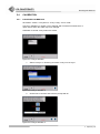
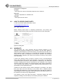
HOW TO SELECT PRODUCT
Click Menu Settings Product to open product management window.
5.3.1.1 Selecting product
Select desired product from the list and click the active button. The machine
restarts when new product is selected.
Figure 5.3-1 Settings window – Product sheet
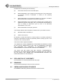
5.3.1.2 Add (How to add new product)
To add a new product:
1.
Click the Add button on the first page of the product sheet.
2.
Select a source product from the list (Figure 5.3-2). The selected
product will be copied to create new product.
3.
Name the product, give it an id-number and click the create button. The
id-number must lie between 1 and 9999.
Figure 5.3-2 Add menu
5 Operation | 6
Scanning Unit J002-872.1
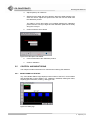
5.3.1.3 Delete a product
To delete a product:
4.
Open the first page of the product sheet.
5.
Choose the product to be deleted.
6.
Click the Delete button.
7.
Choose the product to be deleted from the list (Figure 5.3-3).
8.
Click the Delete button.
Figure 5.3-3 General settings window
Note
It is not possible to delete current product!
5.3.1.4 BackUp
BackUp function copies all the existing products into a memory stick.
Note
If a backup has been already created it will be copied over!
To create a backup copy:
9.
Click the Backup button on the first page of the product sheet.
10. Insert an USB memory stick and click the Backup button (Figure 5.3-4).
11. A backup folder is created into the memory stick and the products are
copied into backup folder.
Figure 5.3-4 Backup
5 Operation | 7
Scanning Unit J002-872.1
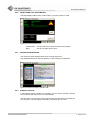
5.3.1.5 Import
Contact JOT Automation to order new products to import.
To import a product:
12. Click the Import button on the first page of the product sheet.
13. Create \Import\ directory into a memory stick and save the desired
products into the directory.
14. Insert a memory stick into an USB port.
15. Click Next.
16. Select products from the import list and click the Import button (Figure
5.3-5).
The imported product is activated automatically.
Figure 5.3-5 Import menu 1
5.3.1.6 Export
To export a product:
17. Click the Export button on the first page of the product sheet.
18. Create \Export\ directory into a memory stick.
19. Insert a memory stick into an USB port.
20. Click the Export button.
21. Select the desired products and click the Export button (Figure 5.3-6).
Figure 5.3-6 Export
5 Operation | 8
Scanning Unit J002-872.1
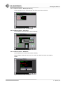
5.3.2
HOW TO TEACH ROBOT POINTS TO PRODUCT
Robot points are taught with a wizard. Wizard starts with Menu Main
TinyService Tiny Config Run Wizard.
Figure 5.3-7 Main – Tiny Service
Follow the instructions given in the wizard windows.
Figure 5.3-8 Insert product width
1.
Insert product width and continue with arrow
Figure 5.3-9 Place the product on the conveyor
2.
Check that there is no product inside the machine and close the prompt
with OK button.
Calibration is taken place.
5 Operation | 9
Scanning Unit J002-872.1
Figure 5.3-10 Place the product on the conveyor
3.
Place the product on the conveyor in the vicinity of the first sensor.
Take product button appears when the sensor detects the product.
4.
Click Take product
The conveyor moves the product to the scanning position. Take product
text turns grey and an arrow appears on the lower right corner.
5.
Click the arrow to continue.
Figure 5.3-11 Hole teaching window
6.
Teach a hole on the PCB to the laser sensor
a. Move the laser pointer to a hole in the PCB with the arrow
buttons.
or
You can also switch on the service mode with Service key
switch, tick on the HandMove and move the robot by hands.
b. When the laser sensor detects a hole IS ON HOLE text
appepars.
c.
Save the location with the Save Location button.
d. Teach other panels’ holes. Select panels from the panel
selection.
7.
Continue with arrow.
5 Operation | 10
Scanning Unit J002-872.1
Figure 5.3-12 Metal surface teaching window
8.
Teach metal surface on the PCB with the same methods as you taught hole.
Figure 5.3-13 Code position teaching window
9.
Teach the 2D code position to the reader with the same methods as
you taught laser sensor. Blue cross shows the code reader position.
Click ManualTrigger or Start Test to test the reader. ManualTrigger
reads the code only once, when the Start Test tests also reading speed.
Results are shown in the display. Fine tune the position to get reading
speed close to 20 DEC/s.
10. Click Finish to end the wizard.
Machine resets itself and loads the taught product.
5 Operation | 11
Scanning Unit J002-872.1
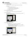
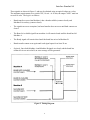
5.3.3
HOW TO CONFIGURE MACHINE POSITION IN LINE (NODE AND IP-ADDRESS)
Click Menu Main TinyService Tiny Config Node Config to open
product management window.
Define here:
·
Tiny line
Several lines may have been connected to the same LMS PC. Lines
are separated with numbering.
·
Tiny zone
Line can include several zones. Zones are separated with numbering.
Every zone includes one master Tiny.
·
Tiny Node
Location number of the machine in the zone.
o Master machine is number 1.
o First slave is number 2 etc.
o Scanning Unit’s node is 130
o Fail Marker’s node is 128
o LMS PC’s node is 129
Machines’ IP-address is generated by means of line, zone and node numbers in
a following way; 200.line.zone.node.
Test PC’s IP-address is generated from the Tiny’s IP-address adding up 100 to
the node number.
Figure 5.3-14 Node configuration
Figure 5.3-15 Lines, zones and nodes
5 Operation | 12
Scanning Unit J002-872.1
5.3.4
HOW TO CORRECT ROBOT POINTS
If robot points taught with teaching wizard need correction, it can be done in
Teaching window.
Click Menu Teaching to open teaching window.
Figure 5.3-16 Teaching sheet
Robot field
Robot selection
Scrolls robots with the prev and next buttons.
Current Coordinates field
Displays current coordinates of the axis or the radius of the index table.
Copy to location
Copies coordinates or radius to the Location
field.
Location field
Indicates saved axes or index point locations, names and positions.
Coordinates or radius are adjusted by copying the coordinates from the
Current coordinate’s field or by placing the cursor to the field.
Arrow buttons
Browses the Locations.
Save loc
Saves adjusted settings.
I/O field
In this field user can use predefined I/Os.
Find I/O list from the automation drawings.
5 Operation | 13
Scanning Unit J002-872.1
Figure 5.3-17 Teaching sheet
Manual Control field
Enable
Turns the actuator/robot power on and enables
manual control.
When the power in not enabled, the
actuator/robot can be moved by hand to desired
locations. After finding the desired location,
press the Copy to location button and after that
the Save loc button.
Calibrate
Executes calibration. Manual control must be
enabled before executing calibration. The index
table must be free and pusher cylinders up.
Move to location
Moves axis or index table to desired location
picked in the Locations field. Manual control
must be enabled and the calibration must be
executed.
Speed
Set axis or index table speed.
Click the robot button to return to the Manual
control field.
Jog
Drive axis manually with the and up
/
down
buttons. Click the control button to
return to the Manual control field.
Figure 5.3-18 Speed and jog fields
5 Operation | 14
Scanning Unit J002-872.1
5.3.5
HOW TO SELECT DATA STORED TO LOG
Selecting Settings Logging, the data saved in the log files can be selected.
The data available is Cycle times, Log errors, and Log results.
To select the logging data, enable the Logger on field, and choose the data for
log files.
Figure 5.3-19 Logging window
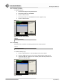
5.3.6
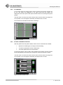
ACTIVATE ERROR ON FAILED READING'
Click Menu Main TinyService Tiny Config Parameters
Select No Read Error Active if you want the machine to alarm and stop when
code reading fails. In another case PCBS are just forwarded straight to the Fail
Module Marker without testing.
Figure 5.3-20 Conveyor calibration
5 Operation | 15
Scanning Unit J002-872.1
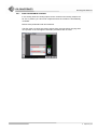
5.4
CALIBRATION
5.4.1
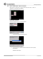
CONVEYOR CALIBRATION
Click Menu Main TinyService Tiny Config Conv Calib
Conveyor calibration is carried out for example after mechanical maintenance or
repair actions when the width may have changed.
Calibration is carried out by means if a wizard.
Figure 5.4-1 Conveyor calibration
1.
Select conveyor. In Scanning Unit there is only one conveyor.
Figure 5.4-2 Conveyor calibration 2
2.
Click arrow to continue and close the prompt with ok.
Figure 5.4-3 Conveyor calibration 2
5 Operation | 16
Scanning Unit J002-872.1
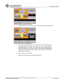
3.
Adjust speed up to maximum
4.
Start driving the width with arrow buttons. When the width appears to be
close the correct, adjust the speed lower and fine tune the width with
the calibration product.
The width is correct when there is no backlash between the calibration
product and the conveyor edges and the calibration pallet moves easily
along the conveyor.
5.
Continue with the arrow button
Figure 5.4-4 Enable power and calibrate
5.5
6.
Insert actual width of the calibration product.
7.
Confirm calibration
CONTROL AND MONITORING
This chapter includes instructions for control and monitoring GUI windows.
5.5.1
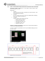
MONITORING DUT STATUS
Tiny Test Handler Status Page displays serial number of the DUT, current status
and pass/fail-data. Current status is e.g. initializing, initialized, reading 2d codes,
acquiring pcb information, marking, driving pcb out.
Figure 5.5-1 Status page
5 Operation | 17
Scanning Unit J002-872.1
5.5.2
MONITORING CELL INFORMATION
Cell page displays status code, product name, cycle time, and error code.
Figure 5.5-2 Cell sheet with an error
5.5.3
Arrow butons
Use to browse error codes if several errors appear.
Retry
Use to retry start after an error.
SEQUENCE MONITORING
The sequence sheet displays status of the running sequences.
The displayed sequences may be helpful e.g. when tracking a malfunction.
Figure 5.5-3 Sequence window in operation state
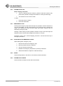
5.5.4
MANUAL CONTROL
In the Manual control window the actuators can be driven manually. Browse
more actuators with the previous and next buttons.
The GUI does not check the chosen actions from the user before carrying them
out. Operator or the cell might be harmed if precautions are not used.
5 Operation | 18
Scanning Unit J002-872.1
5.5.4.1 Manual control – Manual (Actuators)
Product stopper can be used manually with Extend and Retract buttons.
Figure 5.5-4 Manual control of product stopper
5.5.4.2 Manual control – Conveyors
In this window conveyors can be driven manually.
Figure 5.5-5 Manual control of conveyors
5.5.4.3 Manual control – IDReaders
In this window you can test code reader manually.
ManualTrigger reads the code only once, when the Start Test tests also reading
speed.
Figure 5.5-6 Manual control of conveyors
5 Operation | 19
Scanning Unit J002-872.1
5.5.5
I/O CONTROL
In the analog sheet the analog inputs can be monitored and analog outputs can
be set. The inputs are displayed on the upper panel and the outputs are
displayed on the lower panel. Both panels include arrows for scrolling through the
groups.
The GUI does not check the chosen actions from the user before carrying them
out. Operator or the cell might be harmed if precautions are not used.
Find I/O-list from the attached automation drawings.
Figure 5.5-7 I/O sheet
5.5.6
GLOBAL VARIABLE CONTROL
With the global sheet the global variable values can be monitored and modified.
·
Options for variable type are Integer, Real and String.
·
To add new parameters click the add button.
·
To browse parameters use arrow buttons.
An auto save option can be used for the variable types integer and real. Values
will be automatically saved after each change if the auto save option is ticked.
The GUI does not check the chosen actions from the user before carrying them
out. Operator or the cell might be harmed if precautions are not used.
Figure 5.5-8 Global variables sheet
5 Operation | 20
Scanning Unit J002-872.1
5.5.7
ANALOG VARIABLE CONTROL
In the analog sheet the analog inputs can be monitored and analog outputs can
be set. In practice you cannot set outputs because the machine is automatically
controlled.
Browse more parameters with arrow buttons.
The GUI does not check the chosen actions from the user before carrying them
out. Operator or the cell might be harmed if precautions are not used.
Figure 5.5-9 Analog sheet
5 Operation | 21
Scanning Unit J002-872.1
6
MAINTENANCE
6.1
PREPARATIONS FOR MAINTENANCE ................................................................... 2
6.1.1
Detergents .................................................................................................. 2
6.1.2
Lubricants .................................................................................................. 2
6.1.3
Working area .............................................................................................. 2
6.2
MAINTENANCE SCHEDULE ..................................................................................... 3
6.3
MAINTENANCE PROCEDURES ............................................................................... 3
6.4
6.3.1
General condition and function ............................................................... 3
6.3.2
Cleaning ...................................................................................................... 4
6.3.3
Ball screws and linear motion guides ..................................................... 4
6.3.4
Pneumatics ................................................................................................. 4
6.3.5
Cogged belt and pulleys ........................................................................... 5
6.3.6
Sensors ....................................................................................................... 5
RETURNING TO OPERATING MODE ...................................................................... 6
J002-872_1-06C_1_0_1.doc
6 Maintenance instructions | 1
Scanning Unit J002-872.1
6
MAINTENANCE
These instructions are only meant for specially trained maintenance personnel.
Use extreme care when working while the protective covers have been removed.
Note
Only qualified electrician is permitted to open maintenance hatches.
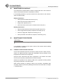
6.1
PREPARATIONS FOR MAINTENANCE
Before starting maintenance, perform following preparations in order to maintain
the machine as easily, safely, and efficiently as possible:
Select tools.
Study carefully:
o
Safety instructions.
o
How to reach the maintenance targets.
o
How to perform the maintenance operation.
Separate the working area e.g. by a colorful rope.
In order to replace a component:
Make sure new component is similar to the one to be replaced.
Remove products remaining in the machine.
For automation documents (circuit diagrams and program disk) see chapter 8
Appendices.
6.1.1
DETERGENTS
For general cleaning of the outer surface, use mild universal cleanser.
For removing grease, use universal grease-remover, e.g.:
6.1.2
LUNGE-SUPER or
WÜRTH PRO-CLEAN (or comparable).
LUBRICANTS
Recommended greases for ball screws and linear guideways:
6.1.3
HIWIN
G05
Klüber
Klüberlub GL-261
Mobil
Mobilux EP1
Fuchs Lubritech Lagermeister BF2
Lubcon
Turmogrease CAK 2502
WORKING AREA
Reserve enough free space around the unit for maintenance procedures.
6 Maintenance instructions | 2
Scanning Unit J002-872.1
6.2
MAINTENANCE SCHEDULE
The maintenance schedule below is meant for single-shift work. If the machine is
used in several shifts shorten the maintenance interval.
If accumulating dust/dirt in a process causes risk to the product or the machine,
clean the machine daily.
Weekly maintenance
Check general condition and function (6.3.1).
Clean outer and inner surfaces (6.3.2).
Empty water separator (6.3.4).
Check and clean sensor lenses, and laser sensor lens (6.3.7).
Monthly maintenance
6.3
Clean and lubricate ball screws and linear guide ways (6.3.3).
Check cogged belt and pulleys. Replace if necessary (6.3.5).
Check air supply filter. Replace if necessary (6.3.4).
Check pneumatic valve silencers. Replace if necessary (6.3.4).
MAINTENANCE PROCEDURES
Warning
Switch the mains off before starting the maintenance!
It is advisable to unplug the main power contact of the machine before starting
the maintenance operation.
6.3.1
GENERAL CONDITION AND FUNCTION
As far as the automation parts are concerned, visually check the cables, sensors,
motors, etc. Make sure that the cables are undamaged. Also pay attention to the
temperature and smell of the components.
Check the door mechanism and other components in the machine and make
sure they move properly. Operate all the functions manually.
Observe the operation of the machine. Make sure it operates smoothly without
any jerking movements or unusual sounds.
When noticing (seeing or hearing) a defect in the machine, immediately take
necessary actions to prevent any damage and find out the fault. Refer to chapter
7 Troubleshooting.
6 Maintenance instructions | 3
Scanning Unit J002-872.1
6.3.2
CLEANING
Use only a lint-free cleaning tissue for general cleaning of the outer surface, and
if needed, mild universal cleaner.
Caution
Do not use abrasive cleaning powders or solvents!
6.3.3
BALL SCREWS AND LINEAR MOTION GUIDES
6.3.3.1 Lubricating linear motion guides
1.
Clean the guides with a lint-free cloth and lubricate lightly. Apply
lubricant to lubrication connection of the block or straight on the rail.
2.
Drive the block back and forth three times with the GUIs manual control.
3.
Repeat lubricating and driving twice.
4.
If a lubricant film cannot be seen on the profile, increase lubricant
quantities.
Caution
Excessive quantities of lubricant may damage the parts.
For recommended lubricants see chapter 6.1.2. Lubricants.
6.3.3.2 Lubricating ball screws
1.
Clean ball screws with a lint-free cloth and lubricate lightly. Apply
lubricant to lubricating connection of the nut or straight on the screw.
2.
Drive the nut back and forth three times with the GUI’s manual control.
3.
Repeat lubricating and driving twice.
4.
If a lubricant film cannot be seen on the ball screw, increase the
lubricant quantities.
Caution
Excessive quantities of lubricant may damage the parts.
For recommended lubricants see chapter 6.1.2. Lubricants.
6.3.4
PNEUMATICS
6.3.4.1 Emptying the water separator
To empty the condensed water from the service unit:
1.
Open the valve under the water separation bowl.
2.
When the bowl is empty (compressed air starts to whistle out), close the
valve.
6 Maintenance instructions | 4
Scanning Unit J002-872.1
6.3.4.2 Replacing air supply filter
Replace air filter if you notice decrease in air pressure.
To replace a filter:
1. Stop the flow of compressed air.
2. Screw off the water separation bowl.
3. Screw off the plastic nut under the filter.
4. Replace the filter element.
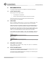
6.3.4.3 Replacing silencers
Check condition of the valve silencers. Every control valve or valve package
contain a silencer or several silencers. In scanning unit the silencers are located
in the stoppers valve. Grey colour or an extraordinary sound when disconnecting
pressure signifies clogging or damage. Replace clogged or damaged silencer.
Figure 6.3-1 Examples of valve silencers
6.3.5
COGGED BELT AND PULLEYS
Check the condition of the cogged belt and cogged belt pulleys.
Replace worn, faulty or loose belt and damaged pulleys.
6.3.6
SENSORS
Clean sensor lenses with a dry lens cloth if necessary. Avoid unnecessary
cleaning. Wipe dust off carefully. Do not use solvents.
6 Maintenance instructions | 5
Scanning Unit J002-872.1
6.4
RETURNING TO OPERATING MODE
After finishing maintenance:
Close opened hatches and mount the removed cover plates.
Check that all cables and clamps are correctly connected and fastened.
Perform the final inspection after the maintenance acceptance.
Pay special attention to the following issues:
Tightness of the cables: the cables must not hang, lie on the floor or be
in touch by a moving element.
Cleanliness of the device and the working area.
The maintenance switches have been returned to the normal operation
mode.
Pneumatic supply has been connected.
The machine is tested according to test instructions in Installation
manual.
When maintenance operations are completed turn the service switch to the 0position and perform starting procedures as described in the operation manual.
6 Maintenance instructions | 6
Scanning Unit J002-872.1
7 TROUBLESHOOTING
7.1
ALARM HANDLING ................................................................................................. 2
7.2
UNEXPECTED DAMAGES ...................................................................................... 2
7.3
7.2.1
Mechanical damages ................................................................................. 2
7.2.2
Water damage ............................................................................................ 3
7.2.3
Fire .............................................................................................................. 3
RECOVERY FROM PROGRAM LOSS ................................................................... 3
J002-872_1-07C_1_0_0.doc
7 Troubleshooting | 1
Scanning Unit J002-872.1
7
TROUBLESHOOTING
This chapter includes troubleshooting guide and instructions on how to handle
unexpected damages. The troubleshooting guide is for trained service personnel
only.
7.1
ALARM HANDLING
Most common errors:
10200
"PCB is in the WRONG orientation, please take out the
PCB and press retry"
10202
"Scanner has count 4 no reads in a row, please check
the reading places and the scanner before continue "
10203
"Scanner could not read a 2D code in the board, please
take the board out, inspect it and retry"
10105
"Door is open, please close the door."
7.2
UNEXPECTED DAMAGES
7.2.1
MECHANICAL DAMAGES
Note
If the machine is displaced by some reason, it is utterly important to check the condition of the
power cord. A damaged cord may cause an electric shock!
Only a qualified electrician may inspect the machine.
If an external force causes a visible change in the shape of the machine:
Turn the mains off immediately.
Unplug the power cord.
Be careful not to touch the machine due to a risk of electric shock.
Pay special attention to any damaged electrical components in the
control system.
The machine must not be used if:
there is any possibility of a risk of electric shock or
a component containing voltage is damaged
7 Troubleshooting | 2
Scanning Unit J002-872.1
7.2.2
WATER DAMAGE
In case of water damage:
1.
Turn the mains off immediately.
2.
Unplug the power cord.
3.
Be careful not to touch the machine due to a risk of electric shock.
Only a qualified electrician may inspect the machine for moisture and make sure
it can be safely used before it is started. The power must be prevented from
being turned on before and during the inspection.
There is always a huge risk of an electric shock. If the inspection indicates that
the machine is dry and not damaged, it may be operated normally.
If noticing moisture damages contact JOT Automation Field Service.
7.2.3
FIRE
Press the Emergency Stop button and follow the internal procedures of your
company or organization for an emergency situation. If fire occurs, use a CO2 fire
extinguisher.
7.3
RECOVERY FROM PROGRAM LOSS
It is advisable to create a backup copy of all the existing products. Refer to
chapter 5.3.3.4 BackUp.
In the case of program loss, import the backup copy. Teach locations manually. If
this does not help, contact JOT Automation.
7 Troubleshooting | 3
Scanning Unit J002-872.1
8
APPENDICES
8.1
RECOMMENDED SPARE PARTS .......................................................................... 2
8.2
HOW TO ORDER SPARE PARTS........................................................................... 3
8.3
WARRANTY ............................................................................................................. 3
8.4
DECLARATION OF CONFORMITY......................................................................... 4
8.5
DRAWINGS .............................................................................................................. 4
8.6
SMEMA HANDSHAKING STANDARD ................................................................... 4
J002-872_1-08C_1_0_1.doc
8 Appendices | 1
Scanning Unit J002-872.1
8
APPENDICES
8.1
RECOMMENDED SPARE PARTS
Spare part code
Part
Bulb
Type
2200017020_0
Ba15D 16x35 24V 125mA 3W
Class
3
ACC06140_0
Mounting bracket
IGUS 0450.20.12
3
ACC06198_0
Energy transfer chain
IGUS 0.585m 045.20.038.0
3
ACC071_0
Door switch
1 opening/closing contact
2
BEA06186_0
Deep groove ball bearing
BEA068_0
Ball bearing 6
CON01145_0
Driver, Brushless DC motor
1.5A RXBL1,5PR
1
CON02123_0
Servo Controller
Faulhaber MCBL3006C-3085
1
CON04265_0
Serial interface
RS232 Beckhoff EL6001
3
CON04271_0
Feed terminal
24VDC Beckhoff EL9100
3
CON04275_0
EtherCAT Coupler
Beckhoff, EK1100
3
CON04283_0
Digital output terminal
3
CON0990_0
2-D Reader
8ch 24 VDC 0,5A
Quadrus MINI FIS-6300-1002G
CON10121_0
Analog output terminal
0-10vdc, 4-channel
3
CON10134_0
Digital Input terminal
8-ch 24vdc 3 ms
3
CON10165_0
Can open
3
DIA0111_0
DIA0168_0
Key switch, NC+NO
Membrane terminal
Beckhoff EL6751
D16mm Round plate
Model 2001, Buttons JMT-11
1
DIA0191_0
Contact block
DRI06495_0
Timing belt
T2,5-6_145
2
DRI06532_0
MXL 2,3mm belt 498
MXL 2,3mm belt 498
1
DRI06664_0
Toothed belt
6T2,5/915
1
ELE0444_0
Relay, Interface
Murrelektronik, code 52003
1
ELE0472_0
Safety relay
Duelco NST-3.2CL 24VAC/DC
1
ELE0628_0
DC-DC converter
6W / 24 VDC - 5VDC
2
ELE06331_0
Power supply
24VDC/80W/3.3A
1
EM049211_0
Spline bushing
BEA01383 / Misumi TSPHB8
3
EM051632_0
Roller Assy
MOT0279_0
DC-Brushless Gearmotor
12W, 24V, Gear 19:1 MAXON
1
MOT03100_0
Brushless DC-Servomotor
36W, 24V, gear 14:1
2
MOT03101_0
Brushless DC-Servomotor
101W, 24V
2
OM015583_0
16-T2,5-20-2
3
OM015871_0
Belt pulley
Ball screw and nut
OM016838_0
Belt pulley
16 T2,5 / 12-2
3
P50751_0
Valve, magnetic
5/3 SMC SY3420-5LOU-M5
3
PNE011170_0
Mount Cylinder
double acting
3
PNE07112.0
Festo LFR-1/8-D-MINI 159630
Omron E3Z-D81
3
SEN0211_0
Filter regulator
Photo cell, PNP
SEN02202_0
Digit Amplifier Laser-sensor
PNP Keyence LV-21AP
1
SEN0229_0
Fork sensor (U shape)
OMRON, EE-SX871P (PNP)
1
SEN02301_0
Coaxial sensor, laser
max 600 mm
1
SEN0357_0
Solid-state switch
SMC D-M9PL PNP
1
TDIA024_0
Emergency stop actuator
EAO 61-3440.4/1+ 51-910
2
2
2
3
3
2
2
3
1
Table 8.1-1 Recommended spare parts
8 Appendices | 2
Scanning Unit J002-872.1
Explanation for Categories:
1st class
- These parts are critical in functional perspective of the machine.
2nd class
- Wearing is dependent on utilization rate.
3rd class
- These parts are less critical.
8.2
HOW TO ORDER SPARE PARTS
In order to purchase spare parts kindly contact:
[email protected]
Phone: +358 10 301 5000
Fax: +358 8 344 425
Before ordering spare parts or requesting maintenance, see product type
(Product), serial number (S.No) and project number (No) from the rating plate.
Figure 8.2-1 Rating plate
8.3
WARRANTY
JOT Automation Ltd. (“JOT”) warrants that the products supplied by JOT,
excluding any products provided by the customer, are free from defects in
material or workmanship for a period of twelve (12) months from the date of the
final acceptance of the product or (if no separate final acceptance procedure is
used) from the date of installation of the product. However, the maximum
warranty period is eighteen (18) months from the date of delivery of the product
from JOT factory.
If during the warranty period a product is found to have an aforementioned
defect, JOT shall repair or replace, at its discretion, such product or its part within
a reasonable time. Products or parts repaired or replaced by JOT under the
warranty including labour shall be warranted for the remainder of the original
warranty period of the product. On request defective parts shall be delivered to
JOT or stored for later inspection. The title to defective parts shall transfer to JOT
upon delivery of the replacement part.
Condition for this warranty is that a written notification is provided to JOT within
thirty (30) days from the discovery of the defect with a detailed product
information and explanation of any alleged deficiencies, and that such product is
made available for JOT’s inspection. JOT shall make the final determination as to
the existence and cause of any alleged defect.
The warranty covers only parts and labour. Customary lodging and travel
expenses resulting from the warranty work shall be paid by the customer.
8 Appendices | 3
Scanning Unit J002-872.1
Excluded from the warranty are the following:
(a)
normal wear and tear and consumable parts;
(b)
defects attributable to the operation and maintenance of the product that
is erroneous, incorrect, in-adequate or contrary to the operating
instructions;
(c)
defects attributable to environmental conditions or a change in conditions
that is detrimental or hazardous to the product operation;
(d)
defects attributable to the product being repaired and/or installed and/or
modified by someone other than JOT or an authorized representative of
JOT, or contrary to instructions given by JOT or an authorized
representative of JOT; and
(e)
defects attributable to third party products.
The warranty shall be void if the product is without JOT’s prior written consent:
(a)
dismantled and/or reinstalled; or
(b)
resold to a third party.
No warranty is made with respect to custom products or products produced to
customer’s specifications except as specifically stated in writing by JOT in the
contract for such custom products.
These terms shall be applied worldwide.
JOT MAKES NO OTHER WARRANTIES, EXPRESSED OR IMPLIED, EITHER
IN FACT OR BY OPERATION OF LAW, AND JOT EXPRESSLY EXCLUDES
AND DISCLAIMS ANY WARRANTY OF MERCHANTABILITY, NONINFRINGEMENT OR FITNESS FOR A PARTICULAR PURPOSE.
JOT SHALL NOT BE LIABLE FOR ANY SPECIAL, CONSEQUENTIAL,
INCIDENTAL OR OTHER SIMILAR INDIRECT DAMAGE AND THE LIABILITY
OF JOT SHALL NOT UNDER ANY CIRCUMSTANCES EXCEED THE
PURCHASE PRICE OF THE PRODUCT.
8.4
DECLARATION OF CONFORMITY
Find Declaration of Conformity attached after this page.
8.5
DRAWINGS
Find mechanical drawings at the back of this document.
8.6
SMEMA HANDSHAKING STANDARD
Find SMEMA handshaking standard at the back of this document.
8 Appendices | 4
DECLARATION OF CONFORMITY
According to Directive 2006/42/EC
We,
JOT Automation Ltd.
Vihikari 10
FI - 90440 KEMPELE
FINLAND
declare under our sole responsibility that the product
Name:
Scanning Unit for Tiny Line
Type:
Version
Serial Number
J002-872
1
(if applicable)
to which this declaration relates is in conformity with the following standards or
other normative documents
Directive:
2006/42/EC
Other Directives:
2004/108/EC
Standards:
SFS-EN ISO 12100-1, -2
EN 60204-1
EN 61000-6-4
Oulu, 2 December 2011
Mika Puttonen
R & D Director
JOT Automation Ltd.
3
2
1
Revision note:
Rev:
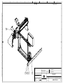
and must not be copied, reproduced or disclosed to any third party without prior written permission. Contravention will be prosecuted.
Designed
unknown1 22.10.2011
unknown1 18.11.2011
Update
Added hose clamps
1
2
This document and its contents are the property of JOT Automation Ltd.
7
6
5
4
8
Drawn
A
A
B
B
Fixed edge
203
Track width
50-150
C
C
D
14
13
12
11
10
9
8
7
6
5
4
3
2
1
No.
E
ACC0687
ACC0690
ACC0687
MAC10026
MAC01461
MAC0577
TMAC0135
MAC10028
MAC01480
OM017831
OM017751
OM017749
OM019348
OM017716
Code
0
0
0
0
0
0
0
0
0
0
0
0
0
0
Ver
Suojaletku, Ulko-D 21.2
Cable hose bracket, D 21.2
Suojaletku, Ulko-D 21.2
Plate washer
Hex socket head cap screw
Cylindrical pin
Hex socket head cap screw
Plate washer
Hex socket head cap screw
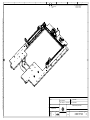
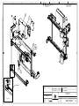
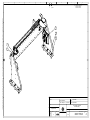
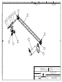
XY-axis assembly
Sensor mounting assembly
Conveyor assembly
Transmission assembly
Base assembly Fail marker
TITLE
Musta polyamidi PA6
Black polyamide
Musta polyamidi PA6
ALE 3,2A DIN125
M3x12 DIN 912 SM
5m6x18 DIN 7
M4x16 DIN 912 SM
ALE 4,3A DIN125
M4x14 DIN 912 SM
Scanner unit
Conveyor Fail marker
TITLE2
1
P
4
P Mec
1
P
2
Mec
2
3
P Mec
4
8
Mec
8
1
A Mec
1
A Mec
1
A Mec
1
A Mec
1
A Mec
QTY Ft Type
D
E
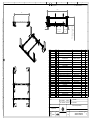
Revision note: Created
Standard:
Designed: unknown1
Drawn:
lamsjuh
29.10.2010 Material: Unspecified
18.11.2011
Back
Copyright (C)
All rights reserved
Scale
Mass: kg
1:5
69.77
Unspecified
XY axis assembly with conveyor
Scanner unit
RoHS:
F
Finish:
F
Size: A3
Metric:mm
Page
Item code . Ver
1/3
OM017832.0
Rev.
2
3
2
1
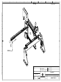
Revision note:
Rev:
and must not be copied, reproduced or disclosed to any third party without prior written permission. Contravention will be prosecuted.
Designed
unknown1 22.10.2011
unknown1 18.11.2011
Update
Added hose clamps
1
2
This document and its contents are the property of JOT Automation Ltd.
7
6
5
4
8
Drawn
A
A
B
B
C
C
9
8
2
6
7
11
10
3
D
D
5
1
E
E
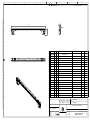
Revision note: Created
Standard:
Designed: unknown1
Drawn:
F
lamsjuh
29.10.2010 Material: Unspecified
18.11.2011
Copyright (C)
All rights reserved
Mass: kg
1:5
69.77
Unspecified
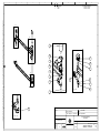
XY axis assembly with conveyor
Scanner unit
RoHS:
Scale
Finish:
F
Size: A3
Metric:mm
Page
Item code . Ver
2/3
OM017832.0
Rev.
2
1
2
3
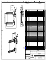
Revision note:
Rev:
Designed
unknown1 22.10.2011
unknown1 18.11.2011
Update
Added hose clamps
1
2
and must not be copied, reproduced or disclosed to any third party without prior written permission. Contravention will be prosecuted.
A
This document and its contents are the property of JOT Automation Ltd.
7
6
5
4
12
13
8
Drawn
14
A
13
13
B
B
13
C
C
D
D
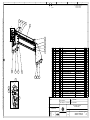
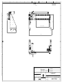
Flont
Frame only for Visual
E
Installed to Frame
E
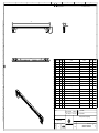
Revision note: Created
Standard:
Designed: unknown1
Drawn:
F
lamsjuh
29.10.2010 Material: Unspecified
18.11.2011
Copyright (C)
All rights reserved
Mass: kg
1:10
69.77
Unspecified
XY axis assembly with conveyor
Scanner unit
RoHS:
Scale
Finish:
F
Size: A3
Metric:mm
Page
Item code . Ver
3/3
OM017832.0
Rev.
2
2
1
3
7
6
5
4
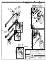
Revision note:
Rev:
Designed
unknown1 30.06.2011
unknown1 30.06.2011
unknown1 19.10.2011
m
brackets changed
Update
1
2
3
8
Drawn
A
This document and its contents are the property of JOT Automation Ltd.
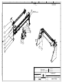
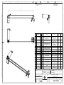
475
B
B
415
C
D
E
762
and must not be copied, reproduced or disclosed to any third party without prior written permission. Contravention will be prosecuted.
A
No. Ref Code
1
OM015956
2
MOT03101
3
OM016838
4
DRI06664
5
OM015871
6
OM015859
7
OM015585
8
BEA068
9
OM015583
10
OM009293
11
OM015956
12
OM015964
13
OM015966
14
M025050
15
OM016674
16
OM017718
17
OM017852
18
OM019052
19
OM019052
20
MAC01120
21
MAC01460
22
MAC01911
23
MAC01785
24
MAC0572
25
MAC01316
26
MAC01476
27
MAC01459
28
MAC01631
29
TMAC0769
30
MAC10028
31
MAC01925
32
OM019337
Ver Rev
0 1
0 0
0 0
0 0
0 1
0 3
0 1
0 2
0 1
0 0
0 0
0 1
0 0
0 1
0 0
0 2
0 0
0 1
0 1
0 4
0 14
0 2
0 21
0 5
0 1
0 21
0 21
0
0
0
0
TITLE
Frame plate
Brushless DC-Servomotor, 101W, 24V
Belt pulley
Toothed belt
Ball screw and nut
Nut housing
Bearing housing
Single row bearing
Belt pulley
Linear guide
Frame plate
Motor barcket
Support plate
Assembly of diverting pulley
Raising bushing
Base plate assembly
Sensor bracket
Connector plate
Connector plate
Socket set screws with cup point
Hex socket head cap screw
Socket low head cap screw
Hex socket head cap screw
Cylindrical pin
Hex socket countersunk head screw
Hex socket head cap screw
Hex socket head cap screw
Hexagon nut
13 Hex socket countersunk head screw
19 Flat washer without chamfer
2 Socket low head cap screw
0 Identification plate
TITLE2
QTY Ft S
1 P Yes
Faulhaber 3564K024B-K1155 1 P Yes
16 T2,5 / 12-2
1 P Yes
6T2,5/915
1 P Yes
2 P Yes
PLT8-20x30
2 P Yes
4 P Yes
686.2Z d=6, D=13, B=5
4
16-T2,5-20-2
2 P Yes
2 P Yes
Mirrored
1 P Yes
1 P Yes
1 P Yes
1 A Yes
1 P Yes
Base assembly Fail marker
1 A Yes
1 P Yes
1 P Yes
1 P
M3x3 DIN 916 SS
10 P Yes
M3x10 DIN 912 SM
4
M3x10 DIN 7984 SM
50 P Yes
M6x14 DIN 912 SS
8
4m6x16 DIN 7
4 P Yes
M2.5x8 DIN 7991 SS
4 P Yes
M4x10 DIN 912 SS
2
M3x10 DIN 912 SS
8
M4 DIN 934 SS
1 P Yes
M4x25 DIN 7991 SS
1 P Yes
M4 DIN 125 SS
1
M4x16 DIN 7984 SM
6 P Yes
1 P Yes
C
D
E
Revision note:
Standard:
Designed: unknown1
Drawn:
F
lamsjuh
20.10.2011
Material:
Unspecified
Finish:
Unspecified
Base assembly Fail marker
RoHS:
Copyright (C)
All rights reserved
Scale
Mass: kg
1:8
0
F
Size: A3
Metric:mm
Page
Item code . Ver
1/3
OM017716.0
Rev.
3
3
2
1
Revision note:
Rev:
21
Designed
unknown1 30.06.2011
unknown1 30.06.2011
unknown1 19.10.2011
m
brackets changed
Update
1
2
3
A
7
6
5
4
8
Drawn
C
11
A
A
This document and its contents are the property of JOT Automation Ltd.
and must not be copied, reproduced or disclosed to any third party without prior written permission. Contravention will be prosecuted.
1
24
10
11
B
15
8
9
22
5
32
B
8
19
26
20
7
13
C
C
A (2 : 3)
4
5
9
14
C (1 : 2)
D
D
2
31
D
22
16
3
E
E
D (2 : 5)
32
17
Revision note:
30
Standard:
Designed: unknown1
Drawn:
F
lamsjuh
20.10.2011
14
Unspecified
Finish:
Unspecified
Base assembly Fail marker
RoHS:
28
Material:
Copyright (C)
All rights reserved
Scale
Mass: kg
1:5
0
F
Size: A3
Metric:mm
Page
Item code . Ver
2/3
OM017716.0
Rev.
3
1
2
3
Revision note:
Rev:
and must not be copied, reproduced or disclosed to any third party without prior written permission. Contravention will be prosecuted.
Designed
unknown1 30.06.2011
unknown1 30.06.2011
unknown1 19.10.2011
m
brackets changed
Update
1
2
3
This document and its contents are the property of JOT Automation Ltd.
7
6
5
4
8
Drawn
A
A
B
B
C
C
D
D
E
E
Revision note:
Standard:
Designed: unknown1
Drawn:
F
lamsjuh
20.10.2011
Material:
Unspecified
Finish:
Unspecified
Base assembly Fail marker
RoHS:
Copyright (C)
All rights reserved
Scale
Mass: kg
1:3
0
F
Size: A3
Metric:mm
Page
Item code . Ver
3/3
OM017716.0
Rev.
3
3
2
1
7
6
5
4
Revision note:
Rev:
Designed
unknown1 01.11.2011
Screws changed
1
8
Drawn
A
This document and its contents are the property of JOT Automation Ltd.
and must not be copied, reproduced or disclosed to any third party without prior written permission. Contravention will be prosecuted.
A
368,7
6
B
2
3
4
5
12
11
B
11
C
C
7
8
13
14
1
D
F
1
15
9
E
Groove
Groove
15
14
13
12
11
10
9
8
7
6
5
4
3
2
1
No.
TMAC0113
MAC01911
MAC10026
MAC01443
MAC01658
OM019349
OM018594
EM049166
OM015869
MOT0279
DRI06495
TMAC0230
BEA06195
EM048246
OM019350
Code
0
0
0
0
0
0
0
0
0
0
0
0
0
0
0
Ver
socket set screw
M 3x 4 DIN914
4
P
Socket low head cap screw
M3x10 DIN 7984 SM
2
P
Flat washer without chamfer
M3 DIN 125 SS
2
Hex socket head cap screw
M2.5x6 DIN 912 SM
3
P
Locking screw
M3x4 DIN 913 SS
4
P
Axle machining
MISUMI TSPR8-60
1
P
Machining of sleeve
Misumi TSPB8
1
P
Machining drawing
2200002175/SYNCHROFLEX AL16T2.5/25-2 1
P
Motor barcket
1
P
DC-Brushless Gearmotor, 12W, 24V, GMAXON EC-Max 22 + GP 22C
1
P
Timing belt
T2,5-6_145
1
P
Lock washer
5 DIN 6799 SS
1
Sealed single row deep groove bearing SKF 619/6-2Z
1
P
Timing Pulley
DRI05101 (Synchroflex Al 16T2.5/19-2)
1
P
Axle machining
MISUMI TSPRW8-300-F25-V6-S0-Q6
1
P
QTY Ft
TITLE
TITLE2
D
E
Revision note: Created
10
Standard:
Designed: unknown1
Drawn:
F
lamsjuh
22.10.2011 Material: Unspecified
01.11.2011
Unspecified
Transmission assembly
RoHS:
F (1 : 1)
Finish:
Copyright (C)
All rights reserved
Scale
Mass: kg
1:2
0
F
Size: A3
Metric:mm
Page
Item code . Ver
1/1
OM019348.0
Rev.
1
1
3
2
7
6
5
4
Revision note:
Rev:
Designed
unknown1 30.06.2011
unknown1 22.10.2011
conveyors changed
Update
1
2
8
Drawn
A
This document and its contents are the property of JOT Automation Ltd.
482
80 Track height
and must not be copied, reproduced or disclosed to any third party without prior written permission. Contravention will be prosecuted.
A
Track width 50-150mm
B
B
4
C
C
5
D
D
3
7
1
2
6
E
No. Ref
Code
Ver Rev
1
OM019067 0 1
2
MAC01762 0
3
OM019072 0 0
4
OM019036 0 0
5
OM019065 0 0
6
OM019065 0 0
7
2200025655 0 2
TITLE
Stopper cylinder assy
Hex socket head cap screw
Conveyor block, fixed edge
Conveyor block, Moving edge
conveyor bracket
conveyor bracket
Miniature fitting, barb elbow for soft tube
TITLE2
M3x35 DIN 912 SS
mirrored
SMC M-3ALU-4
QTY Ft S
1 A Yes
2
1 A
1 A
1 P Yes
1 P
2
E
Revision note:
Standard:
Designed: unknown1
Drawn:
F
lamsjuh
22.10.2011
Copyright (C)
All rights reserved
Mass: kg
1:3
0.13
Unspecified
Finish:
Unspecified
Conveyor assembly
Conveyor Fail marker
RoHS:
Scale
Material:
F
Size: A3
Metric:mm
Page
Item code . Ver
1/1
OM017749.0
Rev.
2
2
1
3
7
6
5
4
Revision note:
Rev:
Designed
unknown1 19.10.2011
unknown1 22.10.2011
update
Update
1
2
8
Drawn
A
A
B
B
C
C
D
D
E
Max. Y-movement 240mm
This document and its contents are the property of JOT Automation Ltd.
and must not be copied, reproduced or disclosed to any third party without prior written permission. Contravention will be prosecuted.
Max. X-movement 290mm
NO. DWGNO VER REV
1 OM017830 0
6
TITLE
Y-Axis assembly
TITLE2
Scanner unit
QTY
1
FTYPE
A
Fail marker assy
1
P
2 OM017753
0
1
Front side support flange
3 OM009293
0
0
Linear guide
1
P
4 OM009293
0
0
Linear guide
2
P
5 OM017764
0
4
x-movement mechanics
1
A
6 MAC01472
0
14
Hex socket head cap screw
M3x6 DIN 912 SM
8
7 MAC01911
0
2
Socket low head cap screw
M3x10 DIN 7984 SM
20
fail marker assy
E
P
Revision note: Created
Standard:
Designed: unknown1
Drawn:
F
lamsjuh
22.10.2011
Copyright (C)
All rights reserved
Mass: kg
1:4
23.15
Unspecified
Finish:
Unspecified
XY-axis assembly
Scanner unit
RoHS:
Scale
Material:
F
Size: A3
Metric:mm
Page
Item code . Ver
1/3
OM017831.0
Rev.
2
1
2
3
Revision note:
Rev:
and must not be copied, reproduced or disclosed to any third party without prior written permission. Contravention will be prosecuted.
Designed
unknown1 19.10.2011
unknown1 22.10.2011
update
Update
1
2
This document and its contents are the property of JOT Automation Ltd.
7
6
5
4
8
Drawn
A
A
B
B
5
C
C
D
D
E
E
Revision note: Created
Standard:
3
F
2
1
4
Designed: unknown1
Drawn:
lamsjuh
22.10.2011
Copyright (C)
All rights reserved
Mass: kg
1:3
23.15
Unspecified
Finish:
Unspecified
XY-axis assembly
Scanner unit
RoHS:
Scale
Material:
F
Size: A3
Metric:mm
Page
Item code . Ver
2/3
OM017831.0
Rev.
2
2
1
3
Revision note:
Rev:
and must not be copied, reproduced or disclosed to any third party without prior written permission. Contravention will be prosecuted.
Designed
unknown1 19.10.2011
unknown1 22.10.2011
update
Update
1
2
This document and its contents are the property of JOT Automation Ltd.
7
6
5
4
8
Drawn
A
A
B
B
6
C
C
3
7
D
D
Dust cap.
Becomes wirh guide
E
E
Revision note: Created
Standard:
Designed: unknown1
Drawn:
F
lamsjuh
22.10.2011
Copyright (C)
All rights reserved
Mass: kg
1:3
23.15
Unspecified
Finish:
Unspecified
XY-axis assembly
Scanner unit
RoHS:
Scale
Material:
F
Size: A3
Metric:mm
Page
Item code . Ver
3/3
OM017831.0
Rev.
2
1
3
2
7
6
5
4
Revision note:
Rev:
Designed
unknown1 28.10.2011
unknown1 18.11.2011
unknown1 30.11.2011
Fastening plates of Reader changed
Hose clamps removed
Added stopper
7
8
9
8
Drawn
A
This document and its contents are the property of JOT Automation Ltd.
B
207
and must not be copied, reproduced or disclosed to any third party without prior written permission. Contravention will be prosecuted.
A
C
Max. stroke 240
101
374
D
E
9
No. Ref
Code
1
OM017767
2
OM009293
3
OM017778
4
OM017792
5
OM017765
6
OM017766
7
OM019281
8
OM017794
9
OM017773
10
OM017769
11
OM017779
12
OM017773
13
OM017768
14
OM017761
15
OM018356
16
OM018249
17
OM018281
18
19
MAC01556
20
MAC01524
21
MAC01635
22
MAC01480
23
MAC01631
24
MAC01472
25
TMAC0135
26
MAC01475
27
MAC0572
28
MAC01564
29
MAC01552
30
MAC01461
31
MAC01770
32
MAC01479
33
MAC10028
34
MAC10026
35
MAC01460
36
MAC01911
37
MAC01478
38
OM019370
39
1100000772
40
OM019347
41
MAC0616
42
MAC01465
Ver TITLE
0 Y-movement frame plate
0 Linear guide
0 Fastening bracket for reader
0 Y movement assembly
0 Support bar
0 Mounting flange
0 Connection plate for belt
0 Motor bracket
0 z-adjustment flange
0 Fastening flange for reader
0 Reader bracket bottom side
0 z-adjustment flange
0 Bracket for energy chain
0 Plate
0 Box assembly
0 Sensor assembly
0 Cylinder bracket
Allen Screw
0 Hex socket countersunk head screw
0 Hex socket head cap screw
0 Hexagon nut
0 Hex socket head cap screw
0 Hexagon nut
0 Hex socket head cap screw
0 Hex socket head cap screw
0 Hex socket head cap screw
0 Cylindrical pin
0 Hex socket countersunk head screw
0 Hex socket countersunk head screw
0 Hex socket head cap screw
0 Hex socket head cap screw
Allen Screw
0 Plate washer
0 Plate washer
0 Hex socket head cap screw
0 Socket low head cap screw
0 Hex socket head cap screw
0 Fastening plate for reader
0 Distance bolt L=35
0 Bracket
0 Vibration absorbers
0 Hex socket head cap screw
TITLE2
Fail marker Y-mechanics
Fail marker y-mechanics
Fail marker
Fail marker Y-mechanics
Fail marker Y-mechanics
Y movement fail marker
Fail marker y-mechanics
Fail marker Y-mechanics
Fail marker y-mechanics
Mirrored
Fail marker Y-mechanics
Fail marker assy
M 3x 6 DIN912
M3x10 DIN 7991 SS
M6x12 DIN 912 SM
M6 DIN 934 Zn
M4x14 DIN 912 SM
M4 DIN 934 Zn
M3x6 DIN 912 SM
M4x16 DIN 912 SM
M3x8 DIN 912 SM
4m6x16 DIN 7
M3x6 DIN 7991 SS
M2x5 DIN 7991 SS
M3x12 DIN 912 SM
M4x50 DIN 912 SM
M 4x 12 DIN912
ALE 4,3A DIN125
ALE 3,2A DIN125
M3x10 DIN 912 SM
M3x10 DIN 7984 SM
M4x12 DIN 912 SM
.
M3-SW5.5 5.13.351
D=8, H=8, M3x6
M3x20 DIN 912 SM
QTY Ft S
1 P Yes
2 P Yes
1 P Yes
1 A Yes
1 P Yes
1 P Yes
2 P Yes
1 P Yes
1 P Yes
1 P Yes
1 P Yes
1 P Yes
1 P Yes
1 P Yes
1 A Yes
1 A Yes
1 P Yes
2
2 P Yes
2
2
1
1
18
4
3
2 P Yes
6 P Yes
2 P Yes
8
2
12
16
4
4
30 P Yes
2
1 P Yes
2 P Yes
1 P Yes
1 P Yes
2
B
C
D
E
Revision note:
Standard:
Designed: vesapaa
Drawn:
F
lamsjuh
28.01.2011 Material: Unspecified
30.11.2011
Copyright (C)
All rights reserved
Mass: kg
1:4
0
Unspecified
Y-Axis assembly
Scanner unit
RoHS:
Scale
Finish:
F
Size: A3
Metric:mm
Page
Item code . Ver
1/4
OM017830.0
Rev.
9
3
2
1
7
6
5
4
Revision note:
Rev:
Designed
unknown1 28.10.2011
unknown1 18.11.2011
unknown1 30.11.2011
Fastening plates of Reader changed
Hose clamps removed
Added stopper
7
8
9
8
A
and must not be copied, reproduced or disclosed to any third party without prior written permission. Contravention will be prosecuted.
27
3
39
17
19
37
16
A
23 13 22
15
This document and its contents are the property of JOT Automation Ltd.
35
8
Drawn
4
30
18
20
24
25
B
B
9
10
C
C
A
41
42
A (2 : 3)
11
40
33
B
D
D
32
2
12
24
C
E
1
2
31
36
Dust cap.
Becomes with guide
E
38
B (2 : 3)
Revision note:
Standard:
6
Designed: vesapaa
Drawn:
33
lamsjuh
28.01.2011 Material: Unspecified
30.11.2011
Copyright (C)
All rights reserved
C (2 : 3)
Scale
Mass: kg
1:3
0
Unspecified
Y-Axis assembly
Scanner unit
RoHS:
F
Finish:
F
Size: A3
Metric:mm
Page
Item code . Ver
2/4
OM017830.0
Rev.
9
3
2
1
7
6
5
4
Revision note:
Rev:
Designed
unknown1 28.10.2011
unknown1 18.11.2011
unknown1 30.11.2011
Fastening plates of Reader changed
Hose clamps removed
Added stopper
7
8
9
8
Drawn
A
A
This document and its contents are the property of JOT Automation Ltd.
and must not be copied, reproduced or disclosed to any third party without prior written permission. Contravention will be prosecuted.
15
21
B
B
C
5
C
32
33
D
D
D
28
7
E
E
Cut the belt
Revision note:
Standard:
Designed: vesapaa
Drawn:
lamsjuh
28.01.2011 Material: Unspecified
30.11.2011
Copyright (C)
All rights reserved
D (2 : 2.5)
Scale
Mass: kg
1:2.5
0
Unspecified
Y-Axis assembly
Scanner unit
RoHS:
F
Finish:
F
Size: A3
Metric:mm
Page
Item code . Ver
3/4
OM017830.0
Rev.
9
1
3
2
Revision note:
Rev:
and must not be copied, reproduced or disclosed to any third party without prior written permission. Contravention will be prosecuted.
Designed
unknown1 28.10.2011
unknown1 18.11.2011
unknown1 30.11.2011
Fastening plates of Reader changed
Hose clamps removed
Added stopper
7
8
9
This document and its contents are the property of JOT Automation Ltd.
7
6
5
4
8
Drawn
A
A
B
B
E
C
C
D
D
18
3
29
E
E
14
E (2 : 2.5)
Revision note:
Standard:
Designed: vesapaa
Drawn:
F
lamsjuh
28.01.2011 Material: Unspecified
30.11.2011
Copyright (C)
All rights reserved
Mass: kg
1:2.5
0
Unspecified
Y-Axis assembly
Scanner unit
RoHS:
Scale
Finish:
F
Size: A3
Metric:mm
Page
Item code . Ver
4/4
OM017830.0
Rev.
9
This document and its contents are the property of JOT Automation Ltd.
3
2
7
6
5
4
Rev:
Revision note:
3
4
5
belts changed
update
Update
Designed
unknown1 22.09.2011
unknown1 19.10.2011
unknown1 22.10.2011
8
Drawn
A
A
B
B
187
and must not be copied, reproduced or disclosed to any third party without prior written permission. Contravention will be prosecuted.
1
C
C
283
NO. DWGNO VER REV
D
E
TITLE
TITLE2
Default/QTY FTYPE
Brushless DC-Servomotor, 36W, 24V, Faulhaber 2444 S024B1
P
gear 14:1
K1155 + 23/1 14:1
Turning wheel axle
bearing 5mm wheel 6mm
2
P
685ZZ,
d=5mm,
Deep groove ball bearing, single row
8
P
D=11mm, B1=5mm
T2,5 -Widht-Length
Tooth belt
2
P
Moulded
bearing housing
2
P
1 MOT03100
0
0
2 OM019320
0
0
3
BEA0215
1
3
4
DRI06656
0
0
5 OM019132
0
0
6 OM019138
0
0
motor bracket
x-movement mechanics
1
P
7 OM017784
8 OM019134
0
0
0
0
Connection bar
Belt pulley
Y-mechanics fail marker
16 T2,5/24-2
1
1
P
P
9 OM019131
0
0
bearing housing
2
P
10 OM017791
0
2
Pulley assembly
y-mechanics fail marker
1
A
11 OM017520
0
0
Belt pulley
16 T2,5 / 24-2
2
P
12 MAC01656
0
10
Locking screw
M3x3 DIN 913 SS
9
P
13 MAC01472
0
2
Hex socket head cap screw
M3x6 DIN 912 SM
2
P
14 MAC01454
0
2
Hex socket head cap screw
M2x5 DIN 912 SM
3
P
15 MAC10026
0
0
Plate washer
ALE 3,2A DIN125
2
D
E
Revision note:
Standard:
Designed: unknown1
Drawn:
F
lamsjuh
22.10.2011
Copyright (C)
All rights reserved
Mass: kg
1:3
0
Unspecified
Finish:
Unspecified
Y movement assembly
Fail marker
RoHS:
Scale
Material:
F
Size: A3
Metric:mm
Page
Item code . Ver
1/2
OM017792.0
Rev.
5
3
2
1
7
6
5
4
Rev:
Revision note:
3
4
5
belts changed
update
Update
Designed
unknown1 22.09.2011
unknown1 19.10.2011
unknown1 22.10.2011
8
Drawn
A
This document and its contents are the property of JOT Automation Ltd.
and must not be copied, reproduced or disclosed to any third party without prior written permission. Contravention will be prosecuted.
A
C
B
B
D
1
6
C
C
11
14
12
10
2
E
4
3
D
D
5
9
3
15
7
13
C (2 : 3)
D (2 : 3)
E
E
8
Revision note:
Standard:
Designed: unknown1
Drawn:
F
E (2 : 3)
lamsjuh
22.10.2011
Copyright (C)
All rights reserved
Mass: kg
1:3
0
Unspecified
Finish:
Unspecified
Y movement assembly
Fail marker
RoHS:
Scale
Material:
F
Size: A3
Metric:mm
Page
Item code . Ver
2/2
OM017792.0
Rev.
5
3
2
1
7
6
5
4
Revision note:
Rev:
Designed
unknown1 23.09.2011
unknown1 23.09.2011
unknown1 20.10.2011
update
1
2
3
8
Drawn
A
This document and its contents are the property of JOT Automation Ltd.
and must not be copied, reproduced or disclosed to any third party without prior written permission. Contravention will be prosecuted.
A
4
6
1
A
3
2
B
B
4
12
9
1
C
No. Ref
Code
1
OM017756
2
OM009293
3
OM017758
4
OM017763
5
OM017759
6
OM019281
7
OM017760
8
OM017762
9
MAC01465
10
MAC01461
11
MAC01478
12
MAC01504
13
MAC01445
14
MAC01911
15
MAC01565
16
MAC0572
17
MAC0577
18
MAC01529
19
MAC01465
20
OM019335
21
TMAC0165
22
MAC0616
23
OM019347
24
2200023314
25
MAC01709
26
MAC01472
16
D
20
3
13
2
18
17
7
8
A (2 : 3)
E
19
23
26
Ver Rev
0 1
0 0
0 1
0 4
0 0
0 1
0 1
0 0
0 14
0 2
0 2
0 2
0 2
0 2
0 14
0 5
0 5
0 2
0 2
0 0
0 2
0 0
0 0
0 0
0 3
0 2
Hex socket head cap screw
TITLE2
Fail marker
Fail marker assy
fail marker assy
Fail marker assy
Fail marker assy
Fail marker assy
M3x20 DIN 912 SM
M3x12 DIN 912 SM
M4x12 DIN 912 SM
M5x16 DIN 912 SM
M2.5x8 DIN 912 SM
M3x10 DIN 7984 SM
M3x8 DIN 7991 SM
4m6x16 DIN 7
5m6x18 DIN 7
M6x20 DIN 912 SM
M3x20 DIN 912 SM
M2x8 DIN 912 SM
D=8, H=8, M3x6
M3 SW6 5.43.070
M3x5 ISO 7380 SS
M3x6 DIN 912 SM
QTY
1
2
1
1
1
1
2
1
2
8
2
4
16
40
2
4
4
6
2
1
2
2
2
3
3
2
Ft S
P Yes
P Yes
P Yes
A Yes
P Yes
P Yes
P Yes
P Yes
P
P
P
P
P
P
P
P
P
P
P
P
P
P
P
P
P
C
D
Yes
Yes
Yes
Yes
Yes
Yes
Yes
E
Yes
Revision note:
Standard:
Designed: unknown1
Drawn:
F
TITLE
Frame plate
Linear guide
Fastening flange
x-movement assembly
Belt bracket
Connection plate for belt
Frame bracket
Mounting flange for energy chain
Hex socket head cap screw
Hex socket head cap screw
Hex socket head cap screw
Hex socket head cap screw
Hex socket head cap screw
Socket low head cap screw
Hex socket countersunk head screw
Cylindrical pin
Cylindrical pin
Hex socket head cap screw
Hex socket head cap screw
Identification plate
Hex socket head cap screw
Vibration absorbers
Bracket
Spacer screw M3 L=7, plastic black
lamsjuh
21.10.2011
Copyright (C)
All rights reserved
Mass: kg
1:3
0
Unspecified
Finish:
Unspecified
x-movement mechanics
fail marker assy
RoHS:
Scale
Material:
F
Size: A3
Metric:mm
Page
Item code . Ver
1/4
OM017764.0
Rev.
4
1
2
3
7
6
5
4
Revision note:
Rev:
Designed
unknown1 23.09.2011
unknown1 23.09.2011
unknown1 20.10.2011
update
1
2
3
8
Drawn
A
A
This document and its contents are the property of JOT Automation Ltd.
and must not be copied, reproduced or disclosed to any third party without prior written permission. Contravention will be prosecuted.
16
Dust cap
Becomes with guide
B
B
17
5
7
6
4
15
12
C
C
9
18
25
21
22
14
D
26
8
D
5
19
E
E
Revision note:
Standard:
Designed: unknown1
Drawn:
F
lamsjuh
21.10.2011
Copyright (C)
All rights reserved
Mass: kg
1:3
0
Unspecified
Finish:
Unspecified
x-movement mechanics
fail marker assy
RoHS:
Scale
Material:
F
Size: A3
Metric:mm
Page
Item code . Ver
2/4
OM017764.0
Rev.
4
1
2
3
7
6
5
4
Revision note:
Rev:
Designed
unknown1 23.09.2011
unknown1 23.09.2011
unknown1 20.10.2011
update
1
2
3
8
Drawn
A
This document and its contents are the property of JOT Automation Ltd.
and must not be copied, reproduced or disclosed to any third party without prior written permission. Contravention will be prosecuted.
A
12
B
B
18
19
5
C
13
C
D
D
E
E
Revision note:
Standard:
Designed: unknown1
Drawn:
F
lamsjuh
21.10.2011
Copyright (C)
All rights reserved
Mass: kg
1:2
0
Unspecified
Finish:
Unspecified
x-movement mechanics
fail marker assy
RoHS:
Scale
Material:
F
Size: A3
Metric:mm
Page
Item code . Ver
3/4
OM017764.0
Rev.
4
2
1
3
7
6
5
4
Revision note:
Rev:
Designed
unknown1 23.09.2011
unknown1 23.09.2011
unknown1 20.10.2011
update
1
2
3
8
Drawn
A
This document and its contents are the property of JOT Automation Ltd.
158
and must not be copied, reproduced or disclosed to any third party without prior written permission. Contravention will be prosecuted.
A
B
B
Max. stroke 290
183,2
458
C
C
D
D
E
E
Revision note:
Standard:
Designed: unknown1
Drawn:
F
lamsjuh
21.10.2011
Copyright (C)
All rights reserved
Mass: kg
1:3
0
Unspecified
Finish:
Unspecified
x-movement mechanics
fail marker assy
RoHS:
Scale
Material:
F
Size: A3
Metric:mm
Page
Item code . Ver
4/4
OM017764.0
Rev.
4
1
2
3
Revision note:
Rev:
and must not be copied, reproduced or disclosed to any third party without prior written permission. Contravention will be prosecuted.
This document and its contents are the property of JOT Automation Ltd.
Designed
unknown1 23.09.2011
unknown1 07.10.2011
unknown1 20.10.2011
turning wheel axle changed
Update
2
3
4
A
7
6
5
4
8
Drawn
328
A
B
B
C
D
E
NO DWGNO VER REV
.
1 MOT03100 0
0
2 OM019320 0
0
TITLE
Brushless DCServomotor, 36W, 24V,
gear 14:1
Turning wheel axle
3
1
3
Deep groove ball
bearing, single row
0
0
0
0
0
0
0
2
0
0
Timing belt
bearing housing
Turn wheel bracket
motor bracket
Belt pulley
0
2
2
0
Allen Screw
Allen Screw
Plate washer
0
10
0
2
0
0
Locking screw
Hex socket head cap
screw
Plate washer
BEA0215
4
5
6
7
8
DRI06689
OM019131
OM017293
OM019138
OM017520
9 MAC0147
9
10
11
12 MAC0165
6
13 MAC0145
4
MAC1002
14
8
M 4x 12 DIN912
M 3x 6 DIN912
ALE 3,2A
DIN125
M3x3 DIN 913 SS
M2x5 DIN 912
SM
ALE 4,3A
DIN125
Revision note:
Standard:
Designed: unknown1
Drawn:
F
lamsjuh
20.10.2011
Copyright (C)
All rights reserved
1:2
Mass: kg
0
Material:
Unspecified
Finish:
Unspecified
2
1
1
6
P
3
P
F
Size: A3
Metric:mm
E
2
x-movement assembly
fail marker assy
RoHS:
Scale
Default/ FTYPE
TITLE2
QTY
C
Faulhaber 2444
S024B-K1155 +
1
P
23/1 14:1
bearing 5mm
1
P
wheel 6mm
685ZZ, d=5mm,
D=11mm,
2
P
B1=5mm
T2,5-6_718
1
P
1
P D
X-movement
1
P
x-movement
1
P
mechanics
16 T2,5 / 24-2
2
P
Page
Item code . Ver
1/2
OM017763.0
Rev.
4
3
2
1
7
6
5
4
Revision note:
Rev:
Designed
unknown1 23.09.2011
unknown1 07.10.2011
unknown1 20.10.2011
turning wheel axle changed
Update
2
3
4
8
Drawn
A
This document and its contents are the property of JOT Automation Ltd.
and must not be copied, reproduced or disclosed to any third party without prior written permission. Contravention will be prosecuted.
A
5
3
12
2
8
4
11
B
10
B
8
C
C
1
14
6
9
D
D
13
7
E
E
Revision note:
Standard:
Designed: unknown1
Drawn:
F
lamsjuh
20.10.2011
Copyright (C)
All rights reserved
1:1.5
Mass: kg
0
Unspecified
Finish:
Unspecified
x-movement assembly
fail marker assy
RoHS:
Scale
Material:
F
Size: A3
Metric:mm
Page
Item code . Ver
2/2
OM017763.0
Rev.
4
1
3
2
7
6
5
4
Revision note:
Rev:
Designed
koskema 26.07.2011
Assembly updated
1
8
Drawn
580
This document and its contents are the property of JOT Automation Ltd.
426
A
5
35
Track Width
50 - 320
B
C
D
E
NO.
1
2
3
DWGNO VER REV
OM019037 0
0
OM019036 0
0
OM018591 0
0
Fixed edge
126
Elevation adjustment
Max. 120
and must not be copied, reproduced or disclosed to any third party without prior written permission. Contravention will be prosecuted.
A
B
TITLE
Conveyor block, Fixed edge
Conveyor block, Moving edge
Transmission assembly
TITLE2
QTY
1
1
1
FTYPE
A
A
A
ITEM0.0.370.03 Profile
5(20x20) - 590mm
L150x75x8-53
PLT2-38x38
Mirrored
2
P
4
1
1
1
8
4
2
2
8
4
8
8
2
8
1
1
1
2
4
6
6
P
P
P
P
4
EM013823
0
0
Aluminium profil
5
6
7
8
9
10
11
12
13
14
15
16
17
18
19
20
21
22
23
24
25
EM013818
EM045884
OM019054
OM019054
MAC01527
MAC01503
MAC01757
MAC01474
MAC10049
MAC10048
MAC10057
MAC10030
MAC10026
MAT0144
OM016173
OM019053
OM019053
TMAC0711
MAC0757
MAT0134
MAC01927
0
0
0
0
0
0
0
0
0
0
0
0
0
0
0
0
0
0
0
0
0
2
1
0
0
21
21
21
21
9
9
10
19
19
0
0
0
0
0
0
2
2
Angle Bracket
Sensor Holder
Connector plate
Connector plate
Hex socket head cap screw
Hex socket head cap screw
Hex socket head cap screw
Hex socket head cap screw
Split lock washer with bend ends
Split lock washer with bend ends
Washer, plain, large
Flat washer without chamfer
Flat washer without chamfer
T-Slot Nut 5 St M5
Support plate
Fastening plate
Fastening plate
Spacer screw L=10 mm
Clamp lever, black
T-Slot Nut 5 St M4
Socket low head cap screw
M6x18 DIN 912 SS
M5x16 DIN 912 SS
M3x14 DIN 912 SS
M3x8 DIN 912 SS
M6 DIN 127 SS
M5 DIN 127 SS
M6 DIN 9021 SS
M5 DIN 125 SS
M3 DIN 125 SS
ITEM 0.0.370.01 (M5)
Mirrored
M3-SW5.5 5.13.101
KIPP 50 105 015 01
ITEM 0.0.370.06 (M4)
M4x8 DIN 7984 SM
C
D
P
P
P
P
P
P
P
P
P
P
P
E
Revision note:
Standard:
Designed: vesapaa
Drawn:
F
koskema
01.03.2011 Material: Unspecified
26.07.2011
Finish:
Unspecified
Return conveyor assembly
RoHS:
Copyright (C)
All rights reserved
Scale
Mass: kg
1:6
6,6902
F
Size: A3
Metric:mm
Page
Item code . Ver
1/2
OM018595.0
Rev.
1
3
2
1
7
6
5
4
Revision note:
Rev:
Designed
koskema 26.07.2011
Assembly updated
1
This document and its contents are the property of JOT Automation Ltd.
and must not be copied, reproduced or disclosed to any third party without prior written permission. Contravention will be prosecuted.
A
8
Drawn
A
C
B
B
B
A
C
C
20
7
25
11
3
C (1 : 2)
1
18
6
23
16
A (1 : 2)
B (1 : 2)
D
D
E
E
19
F
24
5
4
10
9
14
13
16
15
8
12
17
22
21
2
Revision note:
Standard:
Designed: vesapaa
Drawn:
koskema
01.03.2011 Material: Unspecified
26.07.2011
Finish:
Unspecified
Return conveyor assembly
RoHS:
Copyright (C)
All rights reserved
Scale
Mass: kg
1:5
6,6902
F
Size: A3
Metric:mm
Page
Item code . Ver
2/2
OM018595.0
Rev.
1
1
3
2
7
6
5
4
Revision note:
Rev:
Designed
unknown1 23.11.2011
Added gluing instruction
1
8
Drawn
A
This document and its contents are the property of JOT Automation Ltd.
20
482
B
3,5
44
and must not be copied, reproduced or disclosed to any third party without prior written permission. Contravention will be prosecuted.
A
B
C
C
NO. DWGNO VER REV
D
E
TITLE
TITLE2
QTY
FTYPE
1 OM019035
2 OM019026
0
0
1
0
Drive block, 2
Frame plate
1
1
P
P
3 OM019027
0
0
Pulley
5
P
4
DRI06687
0
0
Timing belt
516 MXL widht 2,3mm
1
P
5 OM019031
0
1
Spline bushing
Misumi TSPHB8
1
P
6 OM019030
7 BEA06254
0
0
1
0
Toothed wheel
Ball Bearing MR105ZZ
7,5MXL 32-0
D=10 d=5 B=4
1
10
P
P
8 OM019029
0
1
Bearing housing
1
P
9
BEA06186
0
2
Deep groove ball bearing, single row
1
P
10 OM019032
11 OM019028
0
0
1
0
Tension block, 1
Guide plate
1
2
P
P
12 TMAC023
0
4
External retaining ring
12x1 DIN 471
1
P
13 MAC01564
0
13
Hex socket countersunk head screw
M3x6 DIN 7991 SS
5
P
14 MAC01554
15 MAC01761
0
0
13
21
Hex socket countersunk head screw
Hex socket head cap screw
M2x6 DIN 7991 SS
M3x3 DIN 912 SS
4
1
P
16 MAC01476
0
21
Hex socket head cap screw
M4x10 DIN 912 SS
4
17 MAC01492
0
21
Hex socket head cap screw
M4x40 DIN 912 SS
4
18 MAC01471
0
21
Hex socket head cap screw
M3x5 DIN 912 SS
1
19 MAC01444
0
21
Hex socket head cap screw
M2.5x6 DIN 912 SS
2
20 MAC0563
0
5
Cylindrical pin
3m6x10 DIN 7
4
INA 61801 2Z
D
E
P
Revision note: Created
Standard:
Designed: Lamsaju2
Drawn:
F
lamsjuh
17.06.2011 Material: Unspecified
23.11.2011
Finish:
Unspecified
Conveyor block, Fixed edge
RoHS:
Copyright (C)
All rights reserved
Scale
Mass: kg
1:3
0
F
Size: A3
Metric:mm
Page
Item code . Ver
1/3
OM019037.0
Rev.
1
3
2
1
7
6
5
4
Revision note:
Rev:
Designed
unknown1 23.11.2011
Added gluing instruction
1
8
Drawn
A
This document and its contents are the property of JOT Automation Ltd.
and must not be copied, reproduced or disclosed to any third party without prior written permission. Contravention will be prosecuted.
A
A
B
B
2
C
C
17
16
20
D
D
13
15
12
18
9
3
1
11
4
14
B
E
19
5
8
7
10
Revision note: Created
Standard:
Designed: Lamsaju2
Drawn:
F
E
A (2 : 3)
lamsjuh
17.06.2011 Material: Unspecified
23.11.2011
6
1
Hox.
Use glue to fix parts
5 and 6 together.
Unspecified
Conveyor block, Fixed edge
RoHS:
B (2 : 3)
Finish:
Copyright (C)
All rights reserved
Scale
Mass: kg
1:3
0
F
Size: A3
Metric:mm
Page
Item code . Ver
2/3
OM019037.0
Rev.
1
1
3
2
7
6
5
4
Revision note:
Rev:
Designed
unknown1 23.11.2011
Added gluing instruction
1
8
Drawn
A
This document and its contents are the property of JOT Automation Ltd.
and must not be copied, reproduced or disclosed to any third party without prior written permission. Contravention will be prosecuted.
A
C
B
B
C
C
All text of belt have to remove/overrun.
For examble with black marker pen.
D
D
C (3 : 1)
E
E
Revision note: Created
Standard:
Designed: Lamsaju2
Drawn:
F
lamsjuh
17.06.2011 Material: Unspecified
23.11.2011
Finish:
Unspecified
Conveyor block, Fixed edge
RoHS:
Copyright (C)
All rights reserved
Scale
Mass: kg
1:2
0
F
Size: A3
Metric:mm
Page
Item code . Ver
3/3
OM019037.0
Rev.
1
1
3
2
7
6
5
4
Revision note:
Rev:
Designed
unknown1 23.11.2011
Added gluing instruction
1
8
Drawn
A
This document and its contents are the property of JOT Automation Ltd.
482
20
3,5
44
and must not be copied, reproduced or disclosed to any third party without prior written permission. Contravention will be prosecuted.
A
B
B
C
C
NO. DWGNO VER REV
D
E
TITLE
TITLE2
QTY
FTYPE
1
P
1 OM019034
0
1
Drive block, 1
2 OM019030
3 BEA06186
0
0
1
2
Toothed wheel
Deep groove ball bearing, single row
7,5MXL 32-0
INA 61801 2Z
1
1
P
P
4 OM019031
0
1
Spline bushing
Misumi TSPHB8
1
P
5 OM019033
6 BEA06254
0
0
1
0
Tension block, 2
Ball Bearing MR105ZZ
D=10 d=5 B=4
1
10
P
P
7 OM019027
0
0
Pulley
5
P
8 OM019026
0
0
Frame plate
1
P
9 OM019029
0
1
Bearing housing
1
P
10 DRI06687
0
0
Timing belt
1
P
11 OM019028
0
0
Guide plate
2
P
P
516 MXL widht 2,3mm
12 MAC0563
0
5
Cylindrical pin
3m6x10 DIN 7
4
13 MAC01476
0
21
Hex socket head cap screw
M4x10 DIN 912 SS
4
14 MAC01492
0
21
Hex socket head cap screw
M4x40 DIN 912 SS
4
15 MAC01444
0
21
Hex socket head cap screw
M2.5x6 DIN 912 SS
2
16 MAC01471
0
21
Hex socket head cap screw
M3x5 DIN 912 SS
2
17 TMAC023
0
4
External retaining ring
12x1 DIN 471
1
P
18 MAC01564
0
13
Hex socket countersunk head screw
M3x6 DIN 7991 SS
5
P
19 MAC01554
0
13
Hex socket countersunk head screw
M2x6 DIN 7991 SS
4
P
D
E
Revision note:
Standard:
Designed: Lamsaju2
Drawn:
F
lamsjuh
15.06.2011 Material: Unspecified
23.11.2011
Finish:
Unspecified
Conveyor block, Moving edge
RoHS:
Copyright (C)
All rights reserved
Scale
Mass: kg
1:3
0
F
Size: A3
Metric:mm
Page
Item code . Ver
1/3
OM019036.0
Rev.
1
3
2
1
7
6
5
4
Revision note:
Rev:
Designed
unknown1 23.11.2011
Added gluing instruction
1
8
Drawn
A
This document and its contents are the property of JOT Automation Ltd.
and must not be copied, reproduced or disclosed to any third party without prior written permission. Contravention will be prosecuted.
A
B
B
B
A
13
14
C
C
8
18
B (2 : 3)
D
12
16
6
17
7
11
10
1
2
3
19
15
E
D
E
A (2 : 3)
5
1
9
Hox.
Use glue to fix parts
2 and 4 together.
Revision note:
4
Standard:
Designed: Lamsaju2
Drawn:
F
lamsjuh
15.06.2011 Material: Unspecified
23.11.2011
Finish:
Unspecified
Conveyor block, Moving edge
RoHS:
Copyright (C)
All rights reserved
Scale
Mass: kg
1:3
0
F
Size: A3
Metric:mm
Page
Item code . Ver
2/3
OM019036.0
Rev.
1
1
3
2
7
6
5
4
Revision note:
Rev:
Designed
unknown1 23.11.2011
Added gluing instruction
1
8
Drawn
A
This document and its contents are the property of JOT Automation Ltd.
and must not be copied, reproduced or disclosed to any third party without prior written permission. Contravention will be prosecuted.
A
C
B
B
C
C
All text of belt have to remove/overrun.
For examble with black marker pen.
D
D
E
E
C (3 : 1)
Revision note:
Standard:
Designed: Lamsaju2
Drawn:
F
lamsjuh
15.06.2011 Material: Unspecified
23.11.2011
Finish:
Unspecified
Conveyor block, Moving edge
RoHS:
Copyright (C)
All rights reserved
Scale
Mass: kg
1:2
0
F
Size: A3
Metric:mm
Page
Item code . Ver
3/3
OM019036.0
Rev.
1
1
3
2
7
6
5
4
Revision note:
Rev:
Designed
unknown1 01.11.2011
Screws changed
1
8
Drawn
531,7
A
This document and its contents are the property of JOT Automation Ltd.
and must not be copied, reproduced or disclosed to any third party without prior written permission. Contravention will be prosecuted.
A
2
12
6
4
8
7
1
B
B
5
3
11
C
C
NO. DWGNO VER REV
D
Groove
E
F
1
Groove
9
14
F
TITLE
QTY
FTYPE
1
P
1
P
1
P
1
P
1
1
P
1
P
1
P
1
P
1 OM015869
0
0
Motor barcket
2 OM018592
0
1
Axle machining
3
EM048246
0
0
Timing Pulley
4
BEA06195
0
0
5 TMAC0230
6 DRI06495
0
0
7
0
7
MOT0279
0
0
8
EM049166
0
0
9 OM018594
0
0
10 OM018593
0
2
Axle machining
MISUMI TSPR8-86
1
P
11 MAC01120
0
4
Socket set screws with cup point
M3x3 DIN 916 SS
4
P
12 MAC10026
13 MAC01911
0
0
19
2
Flat washer without chamfer
Socket low head cap screw
M3 DIN 125 SS
M3x10 DIN 7984 SM
2
2
P
14 TMAC0113
0
2
socket set screw
M 3x 4 DIN914
4
P
MISUMI TSPRW8-450-F25V6-S0-Q6
DRI05101 (Synchroflex Al
16T2.5/19-2)
Sealed single row deep groove
SKF 619/6-2Z
bearing
Lock washer
5 DIN 6799 SS
Timing belt
T2,5-6_145
DC-Brushless Gearmotor, 12W, 24V,
MAXON EC-Max 22 + GP
Gear 19:1
22C
2200002175/SYNCHROFLEX
Machining drawing
AL16T2.5/25-2
Machining of sleeve
Misumi TSPB8
D
E
Revision note: Created
Standard:
Designed: Lamsaju2
Drawn:
lamsjuh
31.07.2009 Material: Unspecified
01.11.2011
Finish:
Unspecified
Transmission assembly
RoHS:
Copyright (C)
All rights reserved
10
F (1 : 1)
TITLE2
Scale
Mass: kg
1:2
0
F
Size: A3
Metric:mm
Page
Item code . Ver
1/1
OM018591.0
Rev.
1
Interface Standard 1.2
SMEMA Electrical Equipment Interface Standard
Introduction
The SMEN4A machine interface standards were developed to facilitate the interface of
equipment used in the manufacture of surface-mounted printed circuit boards. This standard is
for Electrical interfaces.
Purpose
The purpose of this standard is to provide an equipment specification for single board transfer
manufacturing systems of surface-mounted printed circuit boards. This specification provides
the minimum requirement that the equipment must meet, and does not represent a complete
specification for the equipment's interface. Conformance to the standard may be achieved by
the appropriate design of the equipment or by providing special adaptors which enable the
equipment to meet the standard.
Figure 1. Electrical Interface Schematic
2
Interface Standard 1.2
Specifications
A machine-to-machine electrical interface is required to insure proper sequencing of PC boards.
The interface is used for "Local" control and must operate independently of the cell controller.
1.) Electrical connections
Each machine should be provided with a
separate power connection and ground.
Individual ON/OFF controls should also be
provided.
2.) Grounding
Each machine should have 1/4-20 earth
ground stud on each side (left and right) of
the machine.
3.) Inter-machine control
To sequence boards properly from machineto-machine, one or two signal lines will be
used: "Board Not Available" and "Board
Available."
3
Interface Standard 1.2
These signals are shown in Figure 2, and may be obtained using an optical isolator or a relay.
The minimum requirements are to switch 3OV, 10 mA. At 10 mA, the output "LOW" must not
exceed 0.8 volts. The logic is as follows:
•
Board transfer occurs when Machine A has a board available (contact closed), and
Machine B is not busy (contact closed).
•
The signals can occur at anytime, but board transfer does not occur until both contacts are
closed.
•
The Board is Available signal from machine A will remain closed until the board has left
Machine A.
•
The Ready signal will remain closed until the board has arrived at Machine B.
•
Board transfer cannot occur again until each signal opens for at least 50 ms.
•
Optional: Once both Machine A and Machine B signals are closed, and the board has
neither left A nor arrived at B, an error message will be generated.
Figure 2. Timing Diagram
4
Interface Standard 1.2
SMEMA Connector Specifications
Figure 4 SMEMA #001: Machine Connector
Figure 4. SMEMA #002: Cable Connector
About SMEMA
The Surface Mount Equipment Manufacturers Association (SMEMA) is a non-profit
organization of companies manufacturing equipment or producing software for surface mount
board production. Its objectives are to: promote standards for the interface and operation of
equipment, provide users with the ability to select equipment with the assurance that the
equipment will interface easily, advance SMT and promote its use and investigate areas where
the association can act to the benefit of all member companies.
5