1
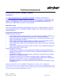
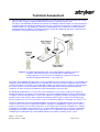
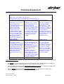
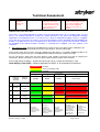
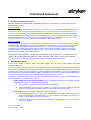
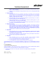
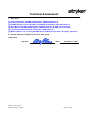
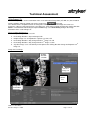
Technical Assessment
HHA Number:
HHA-10-027
RARE Number:
2010-214
Technical Assessment Name: Viewing Direction Change using Multiple Image Sets
Part Number/Product family:
SpineMap® 3D Version 1.0 Products:
6002-650-000, 100, 300, 005,
6002-651-000
81-80045
OrthoMap® 3D Version 1.0 Products:
6005-650-000, 300, 005,
6005-651-000
81-80044
PER Number(s): 201475
Requestor: E. Boettger
Investigator(s): U. Bühner
1. Product Overview:
Provide a brief synopsis of the device and its intended use, including indications for use (e.g. patient
population) and whether the device sustains or supports life?
Stryker Navigation System – SpineMap® 3D Module
Intended Use
The Stryker Navigation System SpineMap® – 3D is intended as a planning and intra-operative
guidance system to enable open or percutaneous computer assisted surgery. The system is
indicated for any medical condition in which the use of computer assisted planning and surgery
may be appropriate. The system can be used for intra-operative guidance where a reference to a
rigid anatomical structure can be identified.
Indications for Use
The Stryker Navigation system – Spine Map 3D supports, but is not limited to, the following
surgical procedures:
• Pedicle screw placement
• Navigation
• Precisely positioning instruments or implants during orthopedic surgery, such as operations
performed with spinal structure, hip and bones in the upper and lower extremities and long
bones.
INQF-11.1 Rev None
Effective: August 1, 2008
Page 1 of 14
Technical Assessment
Stryker Navigation System – OrthoMap® 3D Module
Intended Use
The Stryker Navigation System – OrthoMap® 3D Module is intended as a planning and
intraoperative guidance system to enable open or percutaneous computer assisted surgery. The
system is indicated for any medical condition in which the use of computer assisted planning and
surgery may be appropriate. The system can be used for intra-operative guidance where a
reference to a rigid anatomical structure can be identified.
Indications for Use
The system should be operated only by trained personnel such as surgeons and clinic staff. The
Stryker Navigation System – OrthoMap® 3D Module supports, but is not limited to, the following
surgical procedures:
Orthopedic Oncology Procedures
Surgical Planning Procedures
•
Segmentation to define volumes of interest using correlated, multi-modality image data, e.g.
to assist outlining and visualizing bony structures such as aberrant pathology
•
Image based distance and angular measurement tools, e.g. to define and maintain safety
margins to outlined bony structures
•
Image based resection plane planning to define resections relative to identified structures,
e.g. to support limb salvage surgery taking safety margins into account
•
Virtual screw placement planning in the image data with variable screw length, head-length
and diameter
•
Image based annotation point placement and visualization, e.g. to support repositioning of
bony anatomic points during surgery
Surgical Navigation Procedures
•
•
•
•
Intra-operative visualization of volume image data including visualization of pre-planned
volumes of interest relative to the tracked instrument, supporting navigated excision of userdefined bony structures
Intra-operative visualization of resection planes relative to the tracked instrument on bony
structures assisting bony resections
Intra-operative creation and visualization of annotation points, supporting recording of
landmarks on bony anatomy, e.g. to assist oncology replacement prosthesis repositioning,
leg length and rotation assessment or navigated implant placement
Navigated intra-operative screw placement based on pre-planned or intra-operative virtual
screw definition
®
®
Neither the SpineMap 3D nor the OrthoMap 3D Navigation system does sustain or support life.
The “Planning” versions of the affected products listed above are considered as potentially being part of the
chain of events, but since these products are not used for treatment in the OR any potential harm can only
occur while using the Navigation applications in the OR.
INQF-11.1 Rev None
Effective: August 1, 2008
Page 2 of 14
Technical Assessment
a. Technical Assessment of Risk to Health (List and describe all the known or foreseeable hazards to
the patient or user that may result from the identified discrepancy, attaching supporting testing, technical
reports, complaint analysis, etc. When ever possible discuss the probability of occurrence for each
Hazard and resulting Harm, providing objective evidence to support conclusions):
A reported event occurred with the iNtellect Cranial Software 6000-651-000 used for neurosurgery (refer to
®
®
[6]). Because the SpineMap 3D and OrthoMap 3D Software package contain the same affected function
and were built on the same software code base, this technical assessment is performed.
Initial investigation showed that the symptoms as described in the reported event are based on a systematic
software issue. The issue can only occur when importing a minimum of two patient image sets into the
navigation system consecutively and changing the viewing direction of each imported set.
If the user imports two image sets consecutively and changes the viewing direction for both, the bug only
nd
occurs for the 2nd image set. Instead of changing the viewing direction of the 2 image set, the application
nd
accidentally mirrors the 2 image set and stores the mirrored volume on disk. The image set orientation of
nd
the 2 image set remains correct in system memory until the application is restarted and the data is read
from disk (refer to Attachment A for detailed description of the work flow). Two limitations have been
identified to be significant, if this error scenario occurs:
1.) During planning the image correlation function,
used to overlay two image sets automatically for
image fusion, is affected if the bug occurs, even if
the application has not been restarted. Since the
image correlation uses the stored orientation
nd
labels from the 2 image set on disk, the image
st
correlation tries to correlate the 1 image set to
nd
the mirrored 2 image set. If the imaged section of
the spine is highly symmetric and the section is in
the center and well aligned within the image
volume the automatic correlation might match the
image sets accurately. For spinal structure this
scenario is negligible. Especially the curvature of
the spine makes the mirrored spine look obviously
different compared or overlaid on the non-mirrored
counterpart. A close look to the matching result
shown on the right (Figure 1) shows that the
mirrored (red) bony structure of a lumbar spine
does not really match original image (green). The
3D and also the sectional images show a
significant deviation (refer to Figure 2). This is a
correlation result that would not be confirmed by a
surgeon to be accurate.
Figure 1
Automatic correlation of a lumbar spine CT
segment (L1-L5) with its mirrored CT segment
(same image set).
Figure 2
A closer look to the
result identifies
significant deviations.
The spinal processes
do not match at all.
INQF-11.1 Rev None
Effective: August 1, 2008
Page 3 of 14
Technical Assessment
nd
2.) If the application is restarted, the 2 image set gets loaded with the wrong orientation labels resulting in
a mirrored visualization. Since sections of the spinal column are curved, the image correlation of the nonmirrored and mirrored dataset looks obviously wrong (refer to Figure 3):
Figure 3
Image correlation view after restart of the application using the correlation result
that has been calculated after image import (prior to the restart of the
nd
application): Since the 2 image set is now mirrored, the curvature of the spine
st
obviously does not fit to the 1 image set anymore.
If a confirmed correlation between the first and second image set is available and if the surgeon switches to
nd
st
the 2 image set after registration of the 1 image set, the system will show the mirrored image data of the
nd
2 set if the application has been restarted. Since the spinal column is rarely exactly centered and aligned in
nd
the scanned volume and due to the curvature of the spine the mirrored 2 image set deviates significantly
st
from the correlated 1 image set. In these cases navigation can not be used on the 2nd image set.
For spinal and orthopedic oncology navigation the likelihood of occurrence of the upper described limitations
is rated negligible, because:
1.) For pedicle screw placement, which is the primary application of the spinal navigation system, there is no
medical indication to use multiple image sets. The bony structures of the vertebra to be treated show up
well in a single CT scan. For tumor treatments, e.g. intra-medullary tumors of the spinal cord, and other
orthopedic oncology procedures the use of a second MRI series to also show the oncological soft tissue
situation is feasible. The intended use of the oncology application limits the navigational use to rigid bony
structures.
INQF-11.1 Rev None
Effective: August 1, 2008
Page 4 of 14
Technical Assessment
2.) For both applications there is no medical indication or need to change the viewing direction of the image
data since the surgeons viewing direction during treatment is from the patient’s side.
The Spine- and OrthoMap 3D software inherited the functionality to import multiple set and to change the
viewing direction from the Neuro software package (these image-based packages are built on the same
software code base). For orthopedic surgery this functionality is not used since the standard (default)
viewing direction for radiology (acquisition of images) and for the orthopedic and spine surgeon to view
the patient is “view from feet“ (refer to Figure 4).
Figure 4 For orthopedic applications like spine and orthopedic oncology surgery the
surgeon is either on the patient’s left or right side. In contrast to the
neurosurgeon there is no reason for the orthopedic surgeon to change the
standard viewing direction which is “View from feet”.
The Spine- and OrthoMap 3D applications can be extended by license to integrate with a C-arm providing 3D
volumetric image data intra-operatively. The integration of a 3D C-arm includes an automatic transfer of the
acquired 3D volume via network using the DICOM standard. The image transfer is triggered automatically by
the system and the user has no options to change the orientation of the incoming data. Therefore the
reported issue does not affect navigation based on intra-operative 3D C-arm data.
For orthopedic applications the use of a 2D c-arm to determine e.g. the correct surgical level (spine) or
location (oncology) is commonly used and mitigates the risk if navigational guidance appears inaccurate or
can not be used. The intra-operative use of C-arms allows the surgeon to visualize the surgical instrument’s
position relative to the patient’s bony anatomy intermittently and in real time (single shot and fluoroscopy
mode). Therefore the use of a C-arm can be used as an alternative guidance if navigation can not be used.
To rate the potential harm of the identified limitations listed above, the applications built in and described
safety measures have been reviewed. All hazardous situations are mitigated by safety measures. Every
image set correlation must be confirmed by the user (check box) to be active for navigational use. Prior to
navigation the registration step prompts the user to touch well known landmarks for accuracy confirmation.
According to the safety instructions (refer to [1], [2]) the user is required to perform landmark checks by
comparing the visualization of the actual tool tip relative to the patient’s anatomy on the screen.
INQF-11.1 Rev None
Effective: August 1, 2008
Page 5 of 14
Technical Assessment
The hazardous situations and the potential harms are summarized in the table below:
Precondition
Two image set are imported consecutively
For both image sets the viewing direction is changed by the user.
st
nd
Surgeon plans to register on the 1 image set and to navigate on the 2 image set.
Hazardous situation 1
Hazardous situation 2
Hazardous situation 3
Navigation is to be used for
intra-medullary tumor
removal located asymmetric
in the spinal cord. A
confirmed correlation
between the first and
second image set is
available and the surgeon
nd
switches to the 2 image
set after registration of the
1st image set. The system
will show the mirrored
nd
image data of the 2 set
because the application has
been restarted.
Potential harm 1
The surgeon uses the
nd
information of the 2 image
set (e.g. MRI series) to open
the wrong side of the spinal
cord in order to remove an
intra-medullary tumor. The
tumor is not found on that
side but the cut causes a
potentially irreversible
neurological deficit (refer to
[7]).
1.1
Navigation is to be used for
pedicle screw placement. A
confirmed correlation
between the first and second
image set is available and the
nd
surgeon switches to the 2
image set after registration of
st
the 1 image set. The system
will show the mirrored image
nd
data of the 2 set because
the application has been
restarted.
The image correlation uses
the stored orientation
nd
labels from the 2 image
set on disk and tries to
st
correlate the 1 image set
nd
to the mirrored 2 image
set. Based on the
asymmetry of the spine the
orientation error leads to a
bad correlation result (refer
to Figure 3) after
application restart.
Potential harm 2
Potential harm 3
Opening of the pedicle at the
treatment site might take
longer because the
navigational information does
not match the anatomical and
tactile feedback during
surgery.
The surgeon realizes the
mismatch and continues
treatment of the correct side
using the first image set or
the re-imported second image
set or C-arm vision to finish
the required treatment.
2.1
The surgeon does not
accept the automatic
correlation result and uses
manual or no correlation.
Therefore the situation
might cause a deviation
from the initial surgical plan
nd
because the 2 image set
information can not be
used for navigation.
3.1
Harm Identification Table - Complete the Harm Identification Table below for the event/issue being analyzed.
Describe:
The Hazard (i.e., the potential source of harm) created by the issue/event non-conformance (Note: For
all hazardous situations, all potential harms shall be identified and described).
For each Hazard, the corresponding Foreseeable sequence of events (i.e., circumstance which leads
the Hazard to become a Hazardous situation).
For each Hazard, the corresponding Hazardous situations (i.e., circumstance in which people,
property, or the environment are exposed to one or more hazard(s)).
INQF-11.1 Rev None
Effective: August 1, 2008
Page 6 of 14
Technical Assessment
All Potential Harms (i.e., physical injury or damage to the health of people, or damage to property or the
environment). Each potential harm is numbered to correspond to the related hazard. For example,
hazard 1 may have three harms which would be numbered as 1.1, 1.2, and 1.3.
Refer to Appendix A in INQP-11 Health Hazard procedure for an example Harm Identification Table. When
completing the HIT, the following tips may be useful:
a. Remember that one hazard can result in more than one harm and that more than one sequence
of events can give rise to a hazardous situation. Be sure to discuss all possible hazardous
situations and harms that can result from a hazard.
b. Refer to ISO 14971 Annex D “Risk concepts applied to medical devices,” to provide additional
guidance on overall risk management concepts and additional information that will help complete
the table.
c.
Refer to ISO 14971 Annex E “Examples of hazards, foreseeable sequences of events and
hazardous situations,” for additional information.
Harm Identification Table (HIT):
Hazard
Nbr
Hazard
Description
Foreseeable
sequence of
events
Two image
sets are
imported
consecutively
while for both
sets the
viewing
direction is
changed by
the user.
The application is
used for planning
including image
correlation and is
restarted prior to
the navigated
treatment.
Registration is
st
performed on 1
image set;
navigation is
performed on
nd
correlated 2
image set.
2
Two image
sets are
imported
consecutively
while for both
sets the
viewing
direction is
changed by
the user.
The application is
used for planning
including image
correlation and is
restarted prior to
the navigated
treatment.
Registration is
st
performed on 1
image set;
navigation is
performed on
nd
correlated 2
image set.
3
Two image
sets are
imported
consecutively
while for both
sets the
The application is
used for planning
including image
correlation and is
restarted prior to
the navigated
1
INQF-11.1 Rev None
Effective: August 1, 2008
Hazardous situation
Navigation is to be used
for intra-medullary tumor
removal located
asymmetric in the spinal
cord. A confirmed
correlation between the
first and second image set
is available and the
surgeon switches to the
2nd image set after
registration of the 1st
image set. The system will
show the mirrored image
data of the 2nd set
because the application
has been restarted.
Navigation is to be used
for pedicle screw
placement. The
correlation accuracy
confirmation and the
nd
landmark check on the 2
image set are accepted
because the displayed
anatomical position is
rated accurate. The
surgeon starts locating the
treatment site based on
the flipped anatomical
nd
information of the 2
image set.
The image correlation
uses the stored orientation
labels from the 2nd image
set on disk and tries to
correlate the 1st image set
to the mirrored 2nd image
Potential Harm(s)
1.1
2.1
3.1
The surgeon uses the
information of the 2nd image
set (e.g. MRI series) to open
the wrong side of the spinal
cord in order to remove an
intra-medullary tumor. The
tumor is not found on that side
but the cut causes a potentially
irreversible neurological deficit.
Opening of the pedicle at the
treatment site might take longer
because the navigational
information does not match the
anatomical and tactile feedback
during surgery. The surgeon
realizes the mismatch and
continues treatment of the
correct side using the first
image set or the re-imported
second image set or C-arm
vision to finish the required
treatment. This may result in an
OR time extension of less than
30 minutes.
The surgeon does not accept
the automatic correlation result
and uses manual or no
correlation. Therefore the
situation might cause a
deviation from the initial
Page 7 of 14
Technical Assessment
viewing
direction is
changed by
the user.
treatment.
set. Based on the
asymmetry of the spine
the orientation error leads
to a bad correlation result
(refer to Figure 2) after
application restart
surgical plan because the 2nd
image set information can not
be used for navigation. This
may result in an OR time
extension of less than 30
minutes.
Note: Depending on the number of Hazards and/or Potential Harms identified, the initiating site may need to add
additional rows to the above table.
Since there is no medical indication in pedicle screw placement procedures to use multiple image sets and
there is no medical indication to change the viewing direction in any spinal and orthopedic oncology
applications the likelihood that this issue will occur in spinal or orthopedic oncology surgery is negligible
(refer also to [7]). Based on an analysis of all received complaints for the SpineMap 3D and OrthoMap 3D
product as of today there has been no reported issue that relates to the systemic error described. Therefore
the likelihood of the related hazardous situations is estimated to be negligible, even if the product is not
contained.
b. Harm Analysis Tool - Estimate the likelihood and severity of each of the above Harms identified in the
Harm Identification Tool and plot them on the Harm Analysis Tool risk table below.
Refer to ISO 14971 Annex D “Risk concepts applied to medical devices,” to provide additional guidance on
overall risk management concepts and additional information that will help complete the table.
For any conclusions drawn from the Harm Analysis Tool, provide relevant back-up data to support your
conclusions. Attach extra pages or reference other reports by formal report names/numbers.
Refer to Appendix B in INQP-11, Health Hazard procedure for an example Hazard Analysis Tool.
Harm Analysis Tool (HAT) – Refer to Appendix B of INQP-11 for Completion Instructions:
Intolerable
As low as reasonably possible
Acceptable
Severity Ratings
Likelihood/
Probability
Reference
Reference
Definition
5
High
Occurrence
almost inevitable
4
Moderate
Occurrence
likely
3
Low
Occurrence
possible
2
Remote
Occurrence
unlikely
1
Negligible
Product
contained
1
2
3
4
Negligible
Minimal
Moderate
Serious/Severe
2.1; 3.1
Negligible
Any failure
resulting in no
injury. (example,
annoyance to the
customer)
INQF-11.1 Rev None
Effective: August 1, 2008
Minimal
Any failure
resulting in
transient, selflimiting illness or
injury, not requiring
medical or surgical
intervention.
1.1
Moderate
Any failure
resulting in
reversible injuries
requiring medical
intervention.
Serious/Severe
Any failure
resulting in either
irreversible injuries,
or, damage to a
body structure
which would also
not impair any
bodily function.
Any failure
resulting in death
or serious
deterioration in
the state of health
of any person.
Page 8 of 14
Technical Assessment
2. Review of Risk Management Plan
Was this Hazard/Harm identified in the original Design or Process Risk Analysis, and if so, what was the
likelihood and severity?
Image orientation:
No, the situation is not covered in the current risk assessment. In the systemic error under examination, the
first image set is always orientated correctly while the issue can only occur if a second image set is used.
The risk assessment covers only image orientation errors which are related to image data acquired with a
wrong orientation by the radiology department and loaded into the system. Using images with wrong image
file parameters like pixel size, slice position or image orientation during navigation is rated “severe” in the
current risk analysis (refer to Risk Analysis Project #10326 – Restoration, Rev. H).
Image correlation:
No, the situation is not covered in the current risk assessment. The risk assessment for the image correlation
function assumes correlation of correctly oriented image set. In the worst case scenario under examination a
successful image correlation of the first and second image set can only be performed and accidentally
confirmed to be accurate if the patient’s bony anatomy under treatment is highly symmetric. Incorrect or
inaccurate image correlation during navigation is rated “severe” in the current risk analysis (refer to Risk
Analysis Project #10326 – Restoration, Rev. H).
Do any of the affected products’ Risk Management documents require updating? If so, add the necessary
update to the existing CAPA related to the issue/non-conformance to ensure it is tracked to completion.
Yes, the risk analysis documents of the products under examination have to be updated.
3. Risk Mitigation Factors
Are there any design or process factors that might mitigate risk? Are there specific factors that could
contribute to the risk?
Surgical navigation accuracy depends on several factors that are potentially prone to human error. Starting
with patient preparation and image data acquisition in radiology, patient positioning and fixation in the OR
and finally the surgeon using the navigation system for planning and navigation, each step will contribute to
the final accuracy reached during patient treatment. Knowing this, the system has been designed with built in
status displays and confirmation steps that help to detect potential accuracy issues.
Furthermore safety information (refer to [1], [2]) and imaging protocols (refer to [3]) are shipped with each
product to guide the user to avoid safety issues:
1. Patient preparation and image acquisition process (creation of the patient’s image data). Imaging
Protocol (refer to [3]) lists safety measures including:
a. Verify image orientation and scan quality (no motion artifacts).
b. Safety Information (refer to [1], [2]) contains: “In order to prevent the import of mirrored
images, we recommend to mark the patient’s right side on the acquired images.”
2. Image Import (same task page in all products under examination)
a. Safety Information (refer to [1], [2]): Check the orientation of the patient with respect to the
images. Verify that the orientation labels L (Left), R (Right), A (Anterior), P (Posterior), H
(Head), F (Feet) within the system are correct.
b. System to show image set information, multi-planar reconstruction and 3D visualization
during image import
INQF-11.1 Rev None
Effective: August 1, 2008
Page 9 of 14
Technical Assessment
c.
System to report changed image parameters (e.g. Orientation, Viewing direction) in red on
image set status information
d. System to ask for confirmation of image parameters that have been changed (import dialog
summary)
3. Image correlation
a. Safety Information (refer to [1], [2]): When using image set correlation, ensure and confirm
that the image sets are correlated correctly and accurately with each other. For navigation
accuracy, visually verify the accuracy of the image correlation by using well known
landmarks and the image fusion function.
b. Safety Information (refer to [1], [2]): Note that navigation on correlated image sets adds the
possible correlation error to the registration error.
c.
If two uncorrelated image sets are available while entering the planning page the system
automatically pops up the image correlation dialog
d. The system requires confirmation of the correlated image set pairs before it can be used for
visualization e.g. during planning and navigation
4. Registration planning
a. Safety Information (refer to [1], [2]): For adequate registration, ensure that the reference
points are distributed asymmetrically on anatomically distinctive areas, including points close
to the target of the surgery. Avoid symmetrical distributions like lines, circles, or cylinders.
Select points on rigid, connected structures only. If there is a moveable joint or a fracture,
select the reference points on the side where the patient tracker will be fixed. We
recommend to use a minimum of at least four reference points..
5. Registration
a. Safety Information (refer to [1], [2]): Use well known landmarks, touch them on the patient
and check their match on the displayed images. Adequate registration results are required
for navigation accuracy during surgery.
b. Touch well known landmarks to verify registration accuracy and compare them with the
displayed images (Registration confirmation step).
6. Navigation
a. Safety Information (refer to [1], [2]): After registration, perform continuous landmark
reassessment periodically during the surgery to verify the registration accuracy.
b. Use of intra-operative 3D C-arm scan function for navigation
c.
Use of intra-operative ultrasound for spinal cord tumor tissue localization
nd
If the information of the 2 set is missing for navigation, a surgeon can use an intra-operative C-arm for
guidance on bony structures or an intra-operative ultrasound imaging device for soft tissue guidance (refer to
[7]).
4. User Awareness
Is the discrepancy obvious to the user?
Surgical navigation is used in the OR to execute a treatment plan that is result of surgical planning. Surgical
planning starts with conventional diagnostic imaging to diagnose the patient.
a. The human spine or bones are rarely 100% symmetric and navigation displays and quantifies
asymmetries.
INQF-11.1 Rev None
Effective: August 1, 2008
Page 10 of 14
Technical Assessment
b. During image correlation, the system makes use of overlay colors to help in judging correlation accuracy.
The system requires a checked “Confirmed” box to accept and use an image correlation for planning and
navigation.
c.
Registration, patient fixation and patient tracking are critical for navigation accuracy. Therefore landmark
checks during surgery and prior to use of navigational information are routinely applied.
d. For lateral lesions patient positioning is optimized based on the diagnosis. Any deviation to the other side
if indicated by navigation would raise concerns regarding navigation data integrity.
5. Impact During Surgery
What might the surgeon do if the hazardous situation occurs during surgery? (NOTE: If answer is not known
for this question, obtain a Medical Assessment.)
1. For treatment of bony structures surgeon uses conventional surgery including 2D / 3D C-arm guidance if
patient cannot be treated using navigation (refer to [7]).
2. For localization of intra-medullary tumors intra-operative ultrasound is used instead of navigation (refer to
[7])
3. Lesion side is marked in OR plan – usage of direct pre-surgical timeout (refer to [7])
4. If the user can not find a lesion on the shown side the user would reconfirm the correct side either using
pre-operative or intra-operative images (ultrasound). Using this correct information the operation is
finished on the correct side (refer to [7]).
6. Medical Assessment
Medical Assessments shall be obtained if any of the following conditions exist:
a. The initiating site determines that no Product Field Action is required
b. The Product Field Action is determined to be non-reportable to the site’s home Regulatory
Agency
An initiating site should also consider obtaining a Medical Assessment when the following situations exist:
c.
When evaluating potential hazards for the first time
d. To assist in risk vs. benefits analyses
Do the results of the Medical Assessment require an update to Technical Assessment?
If Yes – Update Technical Assessment form accordingly
Is a Medical Assessment necessary? Yes or No? YES (refer to [7])
If Yes – Arrange for completion of Medical Assessment form, CQF-PMS-002-01-B
If No, provide rationale:
INQF-11.1 Rev None
Effective: August 1, 2008
Page 11 of 14
Technical Assessment
7.
[1]
[2]
[3]
[4]
[5]
[6]
[7]
References
Safety Information, SpineMap 3D Navigation, TD6002650700 Rev. B
Safety Information, OrthoMap 3D Navigation, TD6005650700 Rev. D
CT/MRI Imaging Protocol, SpineMap & OrthoMap 3D Navigation, 6002-650-730 Rev. F
User Manual, SpineMap 3D Navigation, TD6002650740, Rev. C (PDF, part of software)
User Manual, OrthoMap 3D Navigation, TD6005650740, Rev. B (PDF, part of software)
Technical Assessment Cranial - HHA-10-021, RARE 2010-187
Medical Opinion “09_29_2010_CQF-PMS-002-01-B, Medical Assesement_Dr_Hubbe_Spine.pdf”
8. Review, Complete and Approve Technical Assessment
Prepared by:
Signature:
INQF-11.1 Rev None
Effective: August 1, 2008
Date:
rd
November 3 , 2010
Page 12 of 14
Technical Assessment
Attachment A
The software packages under examination make use of 3D medical image data (CT, MR, etc.) that is loaded
into the software during an import step on the “Image Sets”
task page.
The software offers an optional feature to change the viewing direction on the images based on user
preference, either to “view from head” or “view from feet”. It was observed that changing the viewing direction
twice in a well defined order during the import of two image sets consecutively changes the image
orientation of the second image set.
The issue does NOT occur, if
1. Only one image set is used, OR
2. the viewing direction is kept unchanged, OR
3. multiple image sets are imported in separate sessions, OR
st
4. the viewing direction is only changed for the 1 image set, OR
5. the viewing direction is only changed for the 2nd image set, OR
6. any other image set is selected for preview prior to the viewing direction change and import of a 2
image set.
Image Set Task Page
Viewing
direction
selection
Image
box
Selected
image set
Media
content
tree
Image Set
Information
INQF-11.1 Rev None
Effective: August 1, 2008
Page 13 of 14
nd
Technical Assessment
Sequence of events that will lead to the observed event
Import of 2 image sets during one session:
• Startup of software package – create a new patient or select an existing
patient record
st
Change to “Image Set” task page and select (click on) 1 image set from
media content tree for preview
On “Image Set” task page
st
• Change viewing direction of shown 1 image set, e.g. to “View from
Head”. On selection the “Image Set Information” under the images shows
changes parameters for “Orientation”, e.g.: L/PF-> R/P (in red) and for
“Viewing direction”, here “inverted” (in red)
•
•
Press
button under media tree
•
Confirm image set parameters in dialog with OK
•
Click directly on 2
preview
•
Change viewing direction of shown 2 image set, e.g. to “View from
Head”. On selection the “Image Set Information” under the images shows
changes parameters for “Orientation”, e.g.: L/PF-> R/P (in red) but for
“Viewing direction” the parameter remains “as is”.
nd
image set in media content tree for selection and
nd
This indicates that the viewing direction change has NOT been processed
nd
correctly for the 2 image set.
•
Press “Import” button under media tree
• Confirm image set parameters in dialog with OK
nd
The image orientation of the 2 image set has not been changed correctly as required for a viewing direction
change - it has been stored on disk with wrong image orientation labels and will be loaded flipped as soon as
it is loaded from disk, again (e.g. after application restart). If the sequence above is repeated, the image
orientation of every second image set would be affected.
INQF-11.1 Rev None
Effective: August 1, 2008
Page 14 of 14