1
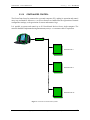
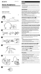
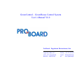
GreenControl – GreenHouse Control System
User’s Manual V6.0
ProBoard – Engenharia Electrotécnica, Lda.
Lugar das Caldas, nº12
4730 – 457 Vila de Prado
BRAGA – PORTUGAL
Tel/Fax : +351 253 924 633
e-mail: [email protected]
url:
www.proboard.pt
GreenControl – User’s Manual V6.0
January, 2007 © ProBoard
Table of Contents
Introduction .................................................................................................................................. 3
Main features ................................................................................................................................ 3
Installation procedures ................................................................................................................. 4
Configuration settings................................................................................................................... 9
Installation settings ..................................................................................................................... 17
Conclusion ................................................................................................................................... 21
1.
2.
MAIN FEATURES ................................................................................................................. 3
INSTALLATION PROCEDURES.......................................................................................... 4
2.1.
LOCATION OF THE GREENCONTROL ...................................................................... 4
2.2.
DIMENSIONS ................................................................................................................ 4
2.3.
CONNECTION ............................................................................................................... 4
2.3.1
POWER................................................................................................................... 4
2.3.2
CONNECTION TO GROUND................................................................................ 4
2.3.3
TEMPERATURE SENSOR..................................................................................... 5
2.3.4
SOLAR RADIATION SENSOR.............................................................................. 5
2.3.5
HUMIDITY SENSOR ............................................................................................. 5
2.3.6
RAIN SENSOR ....................................................................................................... 5
2.3.7
WIND SPEED SENSOR ......................................................................................... 5
2.3.8
WIND DIRECTION SENSOR ................................................................................ 5
2.3.9
OUTPUTS ............................................................................................................... 5
2.3.10 CENTRALIZED CONTROL................................................................................... 6
3. CONCLUSION....................................................................................................................... 7
\This document is confidential and property of ProBoard. It cannot be copied or distributed without permission.
2/7
GreenControl – User’s Manual V6.0
January, 2007 © ProBoard
INTRODUCTION
This User’s Manual presents a description of the
GreenControl main features, operation modes
and installation and setup procedures.
No special knowledge of electronics or
computer science is required to fully exploit its
potentialities. Despite its great number of
features, its operation is extremely easy.
The GreenControl may be controlled locally
through its own interface, which provides access
to the whole system’s features, or, as an option,
remotely, using a personal computer. Up to a
maximum of twenty GreenControl systems may
be linked by a network and fully controlled from
a single personal computer. Both interfaces are
user-friendly and highly intuitive, greatly
reducing the learning cycle.
If you have any further questions upon reading this user’s manual, contact us. We will be happy to
help you.
THE READING OF THIS MANUAL IS INDISPENSABLE FOR THE EFFICIENT
AND SAFE OPERATION OF THE GREENCONTROL SYSTEM!
1. MAIN FEATURES
The GreenControl system is designed to automatically measure and control the climate in a
greenhouse. A set of sensors placed inside the greenhouse are used to measure temperature and
humidity, while another set placed outside are used to measure wind speed, wind direction and solar
radiation and to detect if it is raining or not. The acquired data is used to control of up to four types
of windows (left side, right side, left side roof, and right side roof), shade screen, inflation, heating,
ventilation and fog, in order to keep conditions inside the greenhouse under strict control.
INTERFACES
An 80-characters alphanumeric display (graphical display available as an option) and a 16-key
sealed membrane keypad (no mechanical parts) provide an intuitive and easy way to control and
operate the GreenControl system. Additionally, a computer interface may also be used. This is
specially recommended when several GreenControl systems are installed in a group of greenhouses,
enabling the full control and operation of all systems from one unique place.
\This document is confidential and property of ProBoard. It cannot be copied or distributed without permission.
3/7
GreenControl – User’s Manual V6.0
January, 2007 © ProBoard
SENSORS
The GreenControl can read internal temperature and humidity and can read wind speed, wind
direction, solar radiation and detect if is raining.
It is possible use one metrological station to send information to many GreenControl.
WARRANTY
PROBOARD products are guaranteed against manufacturing defects for a two year period. Local
regulations may override this rule. Please contact our local sales representative for details regarding
this issue.
The warranty does not cover direct and/or indirect damages caused by the use of the equipment.
2. INSTALLATION PROCEDURES
This section should be read by both the installer and the final user.
2.1. LOCATION OF THE GREENCONTROL
The GreenControl should be placed at an appropriate distance from ground (around 1,5 metre) in a
cool and dry place. The equipment should not be exposed to direct sunlight, moisture, dust or
mechanical vibrations.
Do not install it next electromechanical equipment, like electric motors, since electromagnetic
interferences could damage the equipment.
The controller is lodged in an IP65 hermetic box. To maintain it hermetically sealed keep it close
and keep cable glands adequately screwed.
Working temperature: 0 ºC a 40ºC.
Storage temperature: -5 ºC a 50ºC.
2.2. DIMENSIONS
The external dimensions of the GreenControl are: 316 x 226 x 128 mm.
2.3. CONNECTION
Electrical connections must follow electrical installation standards.
2.3.1 POWER
The supply voltage of the GreenControl is 24VAC. It is recommended to keep the power supply
cable as short as possible. The same cable should not be used to supply other devices.
The power consumption of the GreenControl is 4.8VA.
2.3.2 CONNECTION TO GROUND
For the GreenControl to work properly and to prevent future damages a good ground connection, in
compliance with electrical installation standards, is essential.
\This document is confidential and property of ProBoard. It cannot be copied or distributed without permission.
4/7
GreenControl – User’s Manual V6.0
January, 2007 © ProBoard
2.3.3 TEMPERATURE SENSOR
The GreenControl uses calibrated digital temperature sensors. Sensors should be connected to the
system using a 100Ω category 5 cable.
If a more accurate measurement is required (for example, in long greenhouses) it is possible to
install up to 5 temperature sensors. The GreenControl will automatically determine the average
temperature. No additional setup is required.
If a sensor goes out of working the system automatically excludes its reading and keeps on reading
the remaining sensors, using only their information to calculate the average temperature.
2.3.4 SOLAR RADIATION SENSOR
A light-to-current optical sensor with a variable output of 4-to-20mA, which corresponds to a
0-1000W/m2 variation, should be used.
2.3.5 HUMIDITY SENSOR
The GreenControl uses PROBOARD’s proprietary humidity sensors which should be connected to
the system using a 100Ω category 5 cable.
If a more accurate measurement is required (for example, in long greenhouses) it is possible to
install up to 2 humidity sensors. The GreenControl will automatically determine the average
humidity level. No additional setup is required.
2.3.6 RAIN SENSOR
The rain sensor output should consist on a normally-open contact that closes when it starts to rain.
2.3.7 WIND SPEED SENSOR
The sensor should close a contact 6 times, every complete revolution of the anemometer.
Please contact PROBOARD if other types of wind sensors are required.
2.3.8 WIND DIRECTION SENSOR
The wind direction sensor output should consist on a two normally-open contacts. One closes when
the wind comes from the left side and the other one close when the wind comes from the right side.
Please contact PROBOARD if other types of wind sensors are required.
2.3.9 OUTPUTS
The GreenControl has several 1A/24VAC relay outputs, with integrated electrical surge protection,
which protects both the GreenControl system and any external devices.
Depending on the user’s requirements, the GreenControl can control the following greenhouse
elements:
Left side windows
Right side windows
Left side roof-windows
Right side roof-windows
Shade screen
Inflation
Heating
Ventilators
Fog machine
\This document is confidential and property of ProBoard. It cannot be copied or distributed without permission.
5/7
GreenControl – User’s Manual V6.0
2.3.10
January, 2007 © ProBoard
CENTRALIZED CONTROL
The GreenControl may be connected to a personal computer (PC), making its operation and control
more easy and intuitive. Moreover, a set of new features are enabled like the registration of internal
configuration settings, or the generation of sensors and actuators logs.
It is possible to operate and control up to 20 GreenControl devices from a single computer. The
network should be implemented using DATAX PAR (LVCC) 1 x 2 x 0.35 mm2 cable or equivalent.
Gateway
GreenControl
GREENHOUSE 1
GreenControl
GREENHOUSE 2
GreenControl
GREENHOUSE 20
Figure 1: A network of GreenControl systems.
\This document is confidential and property of ProBoard. It cannot be copied or distributed without permission.
6/7
GreenControl – User’s Manual V6.0
January, 2007 © ProBoard
3. CONCLUSION
The GreenControl was developed to enable easy control of any greenhouse.
It is our desire that you feel satisfied using the GreenControl. For support please contact:
ProBoard – Engenharia Electrotécnica, Lda.
Lugar das Caldas, nº12
4730 – 457 Vila de Prado
BRAGA – PORTUGAL
Tel/Fax: +351 253 924 633
e-mail: [email protected]
url:
www.proboard.pt
\This document is confidential and property of ProBoard. It cannot be copied or distributed without permission.
7/7