1
UNIVERSIDAD AUTÓNOMA DE MADRID
ESCUELA POLITÉCNICA SUPERIOR
Transformación de imágenes a vídeo
Proyecto de fin de carrera
Fernando Harald Barreiro Megino
Septiembre 2007
Transformación de imágenes a vídeo
Autor: Fernando Harald Barreiro Megino
Tutor: José María Martínez Sánchez
Grupo de Tratamiento de Imágenes
Departamento de Ingeniería Informática
Escuela Politécnica Superior
Universidad Autónoma de Madrid
Septiembre 2007
PROYECTO FIN DE CARRERA
Título: Transformación de imágenes a vídeo
Autor: Fernando Harald Barreiro Megino
Tutor: José María Martínez Sánchez
Tribunal:
Presidente: Jesús Bescós Cano
Vocal: Pedro Pascual Broncano
Vocal secretario: José María Martínez Sánchez
Fecha de lectura:
Calificación:
Keywords
Content Adaptation, Image browsing, Image to Video transmoding, Regions of Interest (ROIs),
Information fidelity, Visual attention model, Browsing path, Simulated camera movement
Abstract
This master thesis proposes an image to video adaptation system using the human attention
model, in order to view large images on mobile displays without a significant loss of information.
This approach tries to automate the process of scrolling and zooming through an image with a
minimal user interaction by simulating a virtual camera movement through the picture. The process
is automatic and the user interaction will be limited to establish some preferences on the video
generation.
The application depends on an external module, which is commited to define the regions of
interest, which will vary on the domain where this application is used.
The results of the project have been incorporated in the content adaptation framework (named
CAIN) developed within the Sixth Framework Program European project IST-FP6-001765
aceMedia (http://www.acemedia.org/).
Resumen
El objetivo de este proyecto de fin de carrera es investigar en un sistema de adaptación de
imágenes a video, que aproveche el modelo de atención visual humano, para ver imágenes de alta
resolución en dispositivos móviles sin pérdidas significativas de información. La aplicación tratará
de automatizar el proceso de scrolling y zooming a través de una imagen con una interacción
mínima del usuario, que se limitará a establecer sus preferencias en la generación del video.
El sistema de adaptación depende de un módulo de externo, encargado de detectar las regiones
de interés, cuyo tipo variará según el entorno que haga uso del sistema de adaptación.
Los resultados del proyecto se han incorporado en la arquitectura de adaptación de contenido
CAIN, desarrollada en el proyecto europeo del Sexto Programa Marco IST-FP6-001765 aceMedia
(http://www.acemedia.org/).
Agradecimientos
Este trabajo no hubiera sido posible sin la valiosa ayuda de todas las personas que han
colaborado directa o indirectamente en el proyecto y a las que quedo muy agradecido.
En primer lugar quería agradecer a José María Martínez por la posibilidad que me ha
ofrecido de realizar el proyecto de fin de carrera con él y por su trabajo continuo junto a
Jesús Bescós por mejorar la carrera de Ingeniería de Telecomunicación en la UAM.
Durante el desarrollo del proyecto ha sido muy importante la ayuda de Víctor Valdés, que
me ha echado una mano continuamente a lo largo del proyecto y ha colaborado en el
trabajo.
Asimismo quería agradecer a los ocupantes del laboratorio y los miembros del GTI, en
especial Víctor Fernández, Javier Molina y Juan Carlos San Miguel, por su ayuda y por
todo lo que me he podido reír con ellos.
Y en especial a mi padre, mi madre y mi hermana que son lo más importante para mí.
Fernando Barreiro
Septiembre 2007
CONTENTS
Keywords ............................................................................................................................... 4
Abstract .................................................................................................................................. 4
Resumen ................................................................................................................................ 4
Agradecimientos .................................................................................................................... 5
1 Introduction ................................................................................................................... - 1 1.1 Motivation ............................................................................................................ - 1 1.2 Objectives ............................................................................................................. - 1 1.3 Structure of the present document ........................................................................ - 3 1 Introduction ................................................................................................................... - 4 1.1 Motivación ............................................................................................................ - 4 1.2 Objetivos............................................................................................................... - 4 1.3 Organización de la memoria ................................................................................. - 6 2 State of the art ................................................................................................................ - 7 2.1 Visual attention ..................................................................................................... - 7 2.1.1 Information fidelity .................................................................................... - 8 2.1.2 Composite image attention model .............................................................. - 8 2.2 Other approaches to the adaptation of large images to reduced displays ............. - 9 2.2.1 Direct downsampling.................................................................................. - 9 2.2.2 Cropping ..................................................................................................... - 9 2.2.3 Manual browsing ...................................................................................... - 10 2.3 Attention focus detection .................................................................................... - 11 2.3.1 The Viola-Jones face detection method.................................................... - 11 2.3.1.1 Features ................................................................................................... - 12 2.3.1.2 AdaBoost machine learning method....................................................... - 13 2.3.1.3 Scanning an image .................................................................................. - 14 2.3.1.4 Detection results and general comments ................................................ - 14 2.3.2 Face detection in aceMedia: the Convolutional Face Finder ................... - 16 2.3.2.1 Convolutional Neural Network Architecture ......................................... - 16 2.3.2.2 Training the parameters .......................................................................... - 17 2.3.2.3 Face localization ..................................................................................... - 18 2.3.2.4 Detection results ..................................................................................... - 19 2.4 Existing Image2Video approaches ..................................................................... - 20 2.4.1 Image2Video adaptation system - IST Lisbon ......................................... - 21 1. Composite Image Attention Model ............................................................ - 21 2. Attention model integration ........................................................................ - 22 3. Optimal Path Generation ............................................................................ - 22 4. Video Generation ........................................................................................ - 23 2.4.2 Rapid Serial Visual Presentation – Microsoft Research Asia .................. - 23 1. Preprocessing the ROIs .............................................................................. - 24 2. Optimal Path Generation ............................................................................ - 24 3. Dynamic Path Adjusting............................................................................. - 25 2.4.3 Photo2Video – Microsoft Research Asia ................................................. - 25 1. Content Analysis ........................................................................................ - 25 2. Story Generation ......................................................................................... - 26 3. Framing scheme.......................................................................................... - 26 2.4.4 Conclusions .............................................................................................. - 27 2.4.4.1 Differences between the Image2Video approaches................................ - 27 2.4.4.2 Contributions of this master thesis ......................................................... - 28 3 Design .......................................................................................................................... - 29 -
i
3.1 Definitions .......................................................................................................... - 29 3.2 System overview ................................................................................................ - 30 3.3 Internal data structures........................................................................................ - 31 3.3.1 Image structure ......................................................................................... - 31 3.3.2 ROI structure ............................................................................................ - 32 3.3.3 Trajectory structure................................................................................... - 32 3.4 ROI specification files ........................................................................................ - 32 3.5 Zooming and shrinking images .......................................................................... - 34 4 Development ................................................................................................................ - 37 4.1 ROI initialization ................................................................................................ - 37 4.1.1 ROI initialization from file ....................................................................... - 37 4.1.2 Automatic ROI initialization .................................................................... - 38 4.2 Aspect ratio adaptation of the images ................................................................ - 38 4.3 Finding the optimal browsing path ..................................................................... - 41 4.3.1 Jumping to the nearest unvisited ROI ...................................................... - 41 4.3.2 Simulated Annealing ................................................................................ - 41 4.4 Keyframe extraction ........................................................................................... - 44 4.5 Sampling window centering ............................................................................... - 44 4.6 Base speed calculation ........................................................................................ - 45 4.7 Path interpolation for the simulated camera movement ..................................... - 46 4.7.1 Linear interpolation .................................................................................. - 47 4.7.2 Catmull-Rom interpolation ....................................................................... - 48 4.7.3 Arc-length reparameterization .................................................................. - 50 4.7.4 Speed control ............................................................................................ - 52 4.7.5 Zoom control ............................................................................................ - 53 4.7.6 Overview of the interpolated Catmull-Rom curve ................................... - 54 4.8 Camera simulation .............................................................................................. - 54 4.9 Video coding from the temporal image files ...................................................... - 57 5 Integration and testing ................................................................................................. - 59 5.1 Integration of the modules .................................................................................. - 59 5.2 CAIN Integration ................................................................................................ - 61 5.2.1 Mandatory Java class file: Image2VideoCAT.class ................................. - 62 5.2.2 Mandatory XML description file: Image2VideoCAT.xml....................... - 63 5.2.3 Adaptation of the native C code ............................................................... - 66 5.2.4 Modification of the Ffmpeg library .......................................................... - 66 5.3 Testing ................................................................................................................ - 67 5.3.1 Testing environment specifications .......................................................... - 67 5.3.2 Library versions ........................................................................................ - 67 5.3.3 Test examples ........................................................................................... - 68 6 Conclusions and future work ....................................................................................... - 71 6.1 Conclusions ........................................................................................................ - 71 6.2 Future work ........................................................................................................ - 71 6 Conclusiones y trabajo futuro ...................................................................................... - 74 6.1 Conclusiones....................................................................................................... - 74 6.2 Trabajo futuro ..................................................................................................... - 74 References ...................................................................................................................... - 77 Glossary .......................................................................................................................... - 79 Appendices ..................................................................................................................... - 81 A
Running the application ............................................................................ - 81 B
Manual ROI annotation tool ..................................................................... - 83 -
ii
C
CAIN system overview [21] ..................................................................... - 85 C.1. Architecture....................................................................................................... - 85 C.2. Adaptation process ............................................................................................ - 86 C.3. CAIN extensibility ............................................................................................ - 88 D
OpenCV .................................................................................................... - 90 D.1 CxCore ............................................................................................................... - 90 D.2 CvReference ...................................................................................................... - 91 D.3 CvAux ................................................................................................................ - 92 D.4 HighGUI ............................................................................................................ - 93 E
Ffmpeg ...................................................................................................... - 94 PRESUPUESTO....................................................................................................... - 95 -
iii
FIGURE INDEX
FIGURE 1-1: BASIC IMAGE2VIDEO DIAGRAM................................................................................. - 2 FIGURE 1-1: DIAGRAMA BÁSICO DE LA ADAPTACIÓN IMAGE2VIDEO ........................................... - 5 FIGURE 2-1: VISUAL ABILITY TEST (IMAGE TAKEN FROM [8]) ....................................................... - 7 FIGURE 2-2: COMPARISON BETWEEN THE DIFFERENT EXISTING APPROACHES ............................ - 11 FIGURE 2-3: EXAMPLE RECTANGLE FEATURES ............................................................................ - 12 FIGURE 2-4: INTEGRAL IMAGE ..................................................................................................... - 13 FIGURE 2-5: 1. INITIALLY, UNIFORM WEIGHTS ARE DISTRIBUTED THROUGH THE TRAINING
EXAMPLES.
2&3. INCORRECT CLASSIFICATIONS ARE REASSIGNED WITH MORE WEIGHT
(SHOWN AS BIGGER DOTS).
THE FINAL CLASSIFIER IS A WEIGHTED
COMBINATION OF THE WEAK CLASSIFIERS .......................................................................... - 14 FIGURE 2-6: THE CLASSIFIER CASCADE IS A CHAIN OF SINGLE-FEATURE FILTERS ...................... - 14 FIGURE 2-7: PERFORMANCE OF THE VIOLA-JONES DETECTOR .................................................... - 16 FIGURE 2-8: THE CONVOLUTIONAL FACE FINDER (IMAGE COPIED FROM [7]) ............................ - 17 FIGURE 2-9: STEPS IN FACE LOCALIZATION (IMAGE COPIED FROM [7]) ....................................... - 18 FIGURE 2-10: PERFORMANCE OF THE CONVOLUTIONAL FACE FINDER ....................................... - 20 FIGURE 2-11: MICROSOFT’S PHOTOSTORY INITIAL DIALOG ........................................................ - 20 FIGURE 2-12: SYSTEM ARCHITECTURE......................................................................................... - 21 FIGURE 2-13: SYSTEM ARCHITECTURE......................................................................................... - 24 FIGURE 2-14: FLOWCHART OF PHOTO2VIDEO TAKEN FROM [3].................................................. - 25 FIGURE 3-1: EXAMPLES FOR SAMPLING WINDOWS, ROIS AND FRAMES ON A PICTURE ............... - 30 FIGURE 3-2: ROIS2VIDEO ALGORITHM STEPS.............................................................................. - 30 FIGURE 3-3: SPECIFICATION OF A ROI ......................................................................................... - 33 FIGURE 3-4: COMPARISON OF THE PERFORMANCE OF THE DIFFERENT INTERPOLATION METHODS.
FROM LEFT TO RIGHT AND UP TO DOWN, WE HAVE THE ORIGINAL IMAGE, THE INTERPOLATED
IMAGE USING NN INTERPOLATION, USING BILINEAR INTERPOLATION AND BICUBIC
INTERPOLATION. THE IMAGES HAVE BEEN GENERATED SHRINKING THE ORIGINAL IMAGE TO A
RESOLUTION OF 50X50 PIXELS AND THEN ZOOMING IN TO A RESOLUTION OF 1200X1200. - 34 FIGURE 4-1: CLOCKWISE AUTOMATIC VIDEO GENERATION WITHOUT SPECIFICATION OF ROIS . - 38 -
iv
FIGURE 4-2: EXAMPLES FOR THE ASPECT RATIO ADAPTATION IN BAD CASES (A&B) AND IN BETTER
CASES (C&D) ........................................................................................................................ - 40 FIGURE 4-3: TWO SIMULATION EXAMPLES OF THE SIMULATED ANNEALING WITH A RANDOM SET
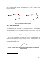
OF DATA POINTS ................................................................................................................... - 43 FIGURE 4-4: EXAMPLES OF KEYFRAMES IN A ROIS2VIDEO SEQUENCE ....................................... - 44 FIGURE 4-5: PIXEL DISTANCE BETWEEN ROIS IN DIFFERENT SIZE PICTURES. ............................. - 46 FIGURE 4-6: INTERPOLATION AND APPROXIMATION .................................................................... - 47 FIGURE 4-7: POSITIONAL, BUT NOT TANGENTIAL CONTINUITY AT THE CENTRAL DATA POINT WHEN
USING LINEAR INTERPOLATION............................................................................................ - 47 FIGURE 4-8: LOCAL CONTROL – MOVING ONE CONTROL POINT ONLY CHANGES THE CURVE OVER A
FINITE BOUND REGION ......................................................................................................... - 49 FIGURE 4-9: THE EFFECT OF C. EXAMPLE OF BROWSING PATHS WITH DIFFERENT CURVATURE
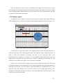
VALUES (FROM STRAIGHT TO EXAGGERATED INTERPOLATIONS), ALL DONE WITH CATMULLROM INTERPOLATIONS......................................................................................................... - 49 FIGURE 4-10: ARC-LENGTH APPROXIMATIONS WITH INCREASING PRECISION. ............................ - 51 FIGURE 4-11: TYPICAL SPEED FUNCTIONS FOR EASE-IN&EASE-OUT CAMERA MOVEMENT. ........ - 52 FIGURE 4-12: PATH BETWEEN ROIS INVOLVING ZOOM FACTOR CHANGE. .................................. - 53 FIGURE 4-13: SOME EXAMPLES FOR THE DEFINED CAMERA MOVEMENT .................................... - 55 FIGURE 4-14: SCHEME OF THE CAMERA SIMULATION. ................................................................. - 56 FIGURE 5-1: IMAGE2VIDEO CAT OPERATION .............................................................................. - 63 FIGURE 6-1: THE SAME SAMPLING WINDOWS CENTRES THE THREE FACES SITUATED AT THE RIGHT
PART OF THE IMAGE. ............................................................................................................ - 71 FIGURE 6-2: SCANNING PATHS FOR SPLITTED ROIS. THE RECTANGLE WITH BOLD STROKES
REPRESENTS THE SAMPLING WINDOW. ................................................................................ - 72 FIGURE 6-1: LA MISMA VENTANA DE MUESTREO CENTRA LAS TRES CARAS DE LAS PERSONAS
SITUADAS EN LA PARTE DERECHA DE LA IMAGEN. .............................................................. - 74 FIGURE 6-1: CAMINOS DE ESCANEADO DE ROIS SUBDIVIDIDAS. EL RECTÁNGULO NEGRO DE
TRAZADO ANCHO REPRESENTA LA VENTANA DE MUESTREO. ............................................. - 76 -
v
TABLE INDEX
TABLE 1: ARC-LENGTH TABLE FOR REPARAMETERIZATION ........................................................ - 51 TABLE 2: DEVELOPMENT OF THE MODULES ................................................................................. - 61 TABLE 3: COMPUTER SPECIFICATIONS ......................................................................................... - 67 TABLE 4: LIBRARY VERSIONS ...................................................................................................... - 68 TABLE 5: EXECUTION RESULTS RUNNING THE ROIS2VIDEO APPLICATION UNDER LINUX ON LAB
COMPUTER 1 ........................................................................................................................ - 69 TABLE 6: STRUCTURES IMPLEMENTED IN CXCORE ..................................................................... - 90 TABLE 7: DYNAMIC STRUCTURES IMPLEMENTED IN CXCORE ..................................................... - 90 TABLE 8: FUNCTIONS AND OPERATIONS IN CXCORE ................................................................... - 91 TABLE 9: FUNCTION CLASSIFICATION IN CVREFERENCE ............................................................. - 92 TABLE 10: FUNCTION CLASSIFICATION IN CVAUX ...................................................................... - 93 TABLE 11: FUNCTION CLASSIFICATION IN HIGHGUI ................................................................... - 93 TABLE 12: COMPONENTS OF FFMPEG........................................................................................... - 94 TABLE 13: MOST IMPORTANT MULTIMEDIA COMPRESSION FORMATS ACCEPTED IN FFMPEG ..... - 94 -
vi
1 Introduction
1.1 Motivation
Communication networks (i.e. mobile, traditional telephone) and Internet are tending towards a
unique universal network, which wants to be accessed via different client devices and with very
different user preferences. Internet providers need to improve their quality of service by offering
adaptive and customized information and content, in order to stand up to the population boom of
mobile equipment (PDAs, smartphones, mobile phones) as Internet clients.
In the foreseeable future the present limitations of mobile devices will get more and more
reduced, as their performance (bandwidth, computational resources, data storage etc) will slowly
converge with the featured performance on desktop computers, and thus becoming more than
sufficient to access Internet and fully profit of its multimedia content. The principal remaining
limitation will then be the screen size, which can not be increased because of mobility and comfort
reasons.
The great deal of information on the Internet presented or shared as images has to be adapted to
this limited screen size. Actually, the predominant methods are downsampling, cropping or manual
browsing of pictures, what involves information loss in the two first cases and time consumption in
the latter case.
1.2 Objectives
A more recent approach to solving the aforementioned adaptation problem of large images to
mobile displays, most commonly known as Image2Video[1][2] or Photo2Video [3], tries to convert
the input image into a video by simulating a fly-through of a virtual camera which will focus on the
regions of interest present in the image. The target of this transmoding1 is to maximize the
information fidelity and the user’s experience [4].
The main objective of this project is to design and develop an Image2Video transmoding tool with
the purpose of generating an output video, which maximizes the information fidelity at the same
time it offers a pleasant presentation. The presentation should take into account some of the
viewer’s preferences, which s/he will be able to introduce before the execution. A basic diagram of
the proposed application is shown in Figure 1-1.
1
Transmoding is refered in the literature as the adaptation that changes the modality –e.g., image,
video, audio, text- of the original media
-1-
Figure 1-1: Basic Image2Video diagram
The development of the Image2Video adaptation tool implies determining the Regions of
Interest2 –ROIs– in an image, finding the optimal browsing path and generating the final video. The
Image2Video application will rely on the external generation of attention objects and will focus on
the video generation. The determination of the regions of interest can be done manually using a
simple graphical user interface (see Annex B) or automatically by any external ROI generation
module. Such an automatical annotation tool has been provided for example by the aceMedia
WorkPackage 4 ([5], [6]), in the form of a convolutional face detector [7].
Although it may look as if the application is designed for leisure purposes, this application can
also be used in many different security applications, where a mobile patrol (ambulance, police,
private security, firemen) is provided with a mobile device and receives a video generated from a
2
A Region Of Interest is used in imaging for defining the boundaries of an object. In medical imaging
the concept is widely spread and used for measuring for example the size of a tumor. In non-medical
imaging, the best known standard is JPEG2000 that specifically provides mechnisms to label the ROIs in an
image.
-2-
large image taken in the crime/accident scene. So, the mobile patrol is able to prepare for the
situation and, given the case, call for reinforcements or a special support unit. This possible system
would only need a specific module to identify the desired objects and ROIs and pass this
information to the Image2Video application.
1.3 Structure of the present document
This memory is structured in the following chapters:
Chapter 1 provides the Introduction(motivation and objectives) of the master thesis
Chapter 2 presents other approaches to adaptation of large images to reduced displays,
as well as the existing Image2Video transmoding systems. In addition, the algorithms
of the external attention focus detection programs, used during the development, will
be shortly introduced.
Chapter 3 presents the architecture of the system and analyzes the data and external
file structures.
Chapter 4 describes the implemented algorithms and offers some insight to the
decisions, problems and solutions found during the implementation.
Chapter 5 covers integration of the system and integration of the application in the
CAIN framework. Testing results of the application.
Chapter 6 presents some of the conclusions obtained after the development of the
system and the possible improvements for future work.
Additionally there are different appendices:
Appendix A: User manual for running the application and execution parameters
Appendix B: Presentation of the graphical user interface’s prototype
Appendix C: Overview of aceMedia’s CAIN system
Appendix D: Description of the OpenCV library
Appendix E: Short description of the Ffmpeg library
-3-
1 Introduction
1.1 Motivación
Las redes de comunicación (por ejemplo de teléfono móvil y teléfono convencional) e Internet
están tendiendo hacia una red universal, que quiere ser accedida desde diferentes dispositivos y con
preferencias de usuario distintas. Los proveedores de Internet necesitan mejorar la calidad de
servicio ofreciendo información y contenido adaptado y personalizado para hacer frente al
crecimiento explosivo de equipamiento móvil (PDAs, teléfonos móviles inteligentes etc.) como
clientes de Internet.
En el futuro previsible, las limitaciones de los dispositivos móviles tenderán a desaparecer
rápidamente, al mostrar rendimientos (velocidad de transferencia de datos, recursos de
procesamiento y de memoria) cada vez más similares a los de ordenadores de sobremesa y siendo
así más que aptos para acceder a Internet y disfrutar del contenido multimedia. La limitación
principal, más difícil de solventar, será el tamaño de pantalla, que no puede crecer por motivos de
comodidad y movilidad.
La gran cantidad de información compartida en Internet en forma de imágenes debe por ello
adaptarse al tamaño reducido de pantalla. Actualmente, los métodos de adaptación predominantes
son reducir el tamaño de la imagen (downsampling), recortar la imagen (cropping) y visualización
manual (manual browsing) de las imágenes, lo que supone pérdida de información en los dos
primeros casos y consumo de tiempo en el último caso.
1.2 Objetivos
Una solución más reciente para realizar la adaptación de imágenes grandes a pantallas de menor
resolución, habitualmente conocida como Image2Video[1][2] o Photo2Video [3], intenta convertir
la imagen de entrada en un vídeo simulando un recorrido de cámara virtual que se centra en las
regiones de interés presentes en la imagen. El objetivo de esta adaptación es maximizar la fidelidad
de información y la calidad de visualización [4].
Por ello, el objetivo principal de este proyecto es diseñar y desarrollar una herramienta de
adaptación Image2Video que genere un video de salida, que ofrezca a la vez alta fidelidad de
información y una presentación agradable. La presentación deberá tener en cuenta algunas
preferencias del espectador, que se podrán fijar durante la ejecución de la herramienta. Un diagrama
básico de la aplicación propuesta se muestra en Figure 1-1.
-4-
Figure 1-1: Diagrama básico de la adaptación Image2Video
El desarrollo de la herramienta de adaptación Image2Video implica determinar las regiones de
interés –ROIs3- de una imagen, encontrar el recorrido óptimo y generar el vídeo final. La aplicación
dependerá de la identificación externa de los objetos de atención y se centrará en la generación del
vídeo. La determinación de regiones de interés se puede realizar manualmente usando una interfaz
gráfica (véase Annex B) o automáticamente usando cualquier módulo de determinación de ROIs,
como el Convolutional Face Finder facilitado por aceMedia en su paquete de trabajo WP4 ([5] [6]
[7]).
Aunque pueda parecer que la aplicación esté dirigida a propósitos de entretenimiento, la
aplicación puede usarse en una gran variedad de entornos, como por ejemplo aplicaciones de
seguridad y vigilancia, donde una patrulla móvil (ambulancia, policía, bomberos, seguridad
privada) está provista de un dispositivo móvil y recibe un vídeo generado a partir de una imagen de
3
Las regiones de interés ROIs se usan en el campo del tratamiento de imágenes para definir los
límites de un objeto. En tratamiento de imágenes médico el concepto es comúnmente conocido y usado para
medir por ejemplo el tamaño de un tumor. En tratamiento de imágenes no-médico el estándar más conocido
es JPEG2000 que incluye mecanismos de anotación de ROIs en una imagen.
-5-
alta resolución tomada en la zona de los hechos. De esta manera, la patrulla móvil puede prepararse
para la situación que les espera y, dado el caso, pedir refuerzos o unidades especiales de apoyo. El
sistema de seguridad necesitaría un módulo de identificación de ROIs para los objetos deseados y
pasar esta información a la aplicación de adaptación Image2Video.
1.3 Organización de la memoria
Esta memoria está dividida en los siguientes capítulos:
Capítulo 1: presenta la introducción (motivación y objetivos) del proyecto fin de
carrera.
Capítulo 2: muestra otros intentos de adaptación de imágenes grandes a pantallas de
baja resolución, así como los programas existentes de Image2Video. Además se
describirán los módulos de identificación de ROIs, particularmente de caras, que se han
usado durante el desarrollo de la aplicación.
Capítulo 3: Presenta la arquitectura del sistema y analiza las estructuras de datos
internas y de los ficheros externos.
Capítulo 4: Describe los algoritmos implementados y ofrece una visión de las
decisiones, problemas y soluciones tomadas durante la implementación.
Capítulo 5: Cubre la integración del sistema durante su desarrollo independiente así
como en la arquitectura de adaptación de contenido CAIN. También muestra los
resultados de las pruebas realizadas.
Capítulo 6: Presenta algunas conclusiones obtenidas después del desarrollo y enumera
las posibilidades de mejora para trabajo futuro.
Adicionalmente hay diferentes apéndices:
Apéndice A: Manual de usuario para ejecutar correctamente la aplicación.
Apéndice B: Presentación del prototipo para la interfaz gráfica de usuario.
Apéndice C: Visión general del sistema CAIN.
Apéndice D: Descripción de la librería OpenCV.
Apéndice E: Breve descripción de la librería Ffmpeg.
-6-
2 State of the art
2.1 Visual attention
The Image2Video application is based upon visual attention models observed in humans and
takes advantage of some of its limitations [8]. When watching a picture, the viewer centers his
attention on some particular regions, which in many applications and papers ([1][3][9][10]) are said
to be faces, texts and other saliencies. Nonetheless, it is important to underline that our application
is independent of the semantic value of the regions of interest and is not bound to a specific type of
visual attention or object detector. The Image2video tool could be used for any possible type of
object, for example cars, trains etc. in particular video surveillance systems.
Furthermore, what allows the trading between space and time is the fact that a viewer is only
capable of centering his attention on just one of these regions of interest, because the human being
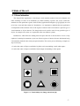
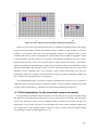
is dramatically limited in his visual perception faculties. This can be proven following a simple two
step exercise [8]:
1. Look at the centre of figure x and find a big black circle surrounding a small white square
2. Look at the centre of figure x and find a black triangle surrounding a white square
Figure 2-1: Visual ability test (Image taken from [8])
-7-
Although you can see all the patterns in the image, your ability to process visual stimuli is
limited and you do not know immediately that the first requested item is present at the lower left
location and that the second requested item is not present at all. In order to perform the requested
task, you have to restrict your visual processing to one at a time. This way, if you obeyed the
instructions and kept your eyes on the central fixation point, you changed your processing of the
visual input over time without changing the actual input.
The Image2Video uses this fact and shows each attention object individually one after another.
To allow a general overview of the image, the whole image will be shown at the beginning and end
of the video.
2.1.1 Information fidelity
The term information fidelity introduces a subjective comparison between the information
contained in an original image and the information maintained after its adaptation: transmoding in
our case. Chen et al. propose a numerical formula for information fidelity in [11], defining its range
from 0 (all information lost) to 1 (all information maintained). Thus, the optimal solution of image
adaptation will try to maximize this number under various client context constraints. According to
these authors, the resulting information fidelity of an image I, consisting of several attention
objects, can be calculated as the weighted sum of the information fidelity of all attention objects in
I:
IF ( I ) =
∑ AV
ROI i ⊂ I
i
⋅ IFAOi
AVi: Attention Value
IFAOi: Information Fidelity of the ith attention object
AOi: ith Attention Object in the image
ROIi: Region Of Interest. Determines the spatial region covered by the ith AO
Thus, the Image2Video application has to show all the image’s attention objects to reach an
information fidelity close to the maximum.
2.1.2 Composite image attention model
Another common definition to most existing papers on Image2Video transmoding is the
concept of attention object ([1][11]etc). An attention object is an information carrier that often
represents semantic classes such as faces, texts, objects or saliencies in the image. Generally, the
viewer focuses mainly on these attention objects, where most of the information that wants to be
transmitted is concentrated on an image. The most complete set to determine an attention object is
{AOi}= {(ROIi, AVi, MPSi, MPTi)}, 1≤i≤N
where
-8-
AOi: ith Attention Object in the image
ROIi: Region Of Interest, which mainly determines the spatial region occupied by
the ith AO
AVi: Attention Value
MPSi: Minimal Perceptible Size of AOi
MPTi: Minimal Perceptible Time of AOi
N: Number of attention objects
As stated in the definition, an attention object needs a minimal spatial resolution and a minimal
displaying time in order to be correctly recognized. When displaying the attention objects of an
image in the generated video, these values have to be taken into account somehow.
Generally, if possible, the regions of interest will be displayed in their full original resolution. If
the region’s size compared to that of the display is small, the attention object can be interpolated
and displayed in a greater size. The maximal interpolation will be left to the user, who can decide
and establish his preferences. If he desires to zoom in too much, the attention object may appear
pixelated.
In the opposite case, when the attention object is greater than the display, it has to be
downsampled or split in more segments. Faces will not be split, as it is more pleasant for the
viewer when they are presented entirely.
2.2 Other approaches to the adaptation of large images to
reduced displays
2.2.1 Direct downsampling
Image downsampling clearly results in an important information loss, as the resolution is
reduced excessively in many cases. Downsampled images can be compared to thumbnail images,
which are used to recognize an image, but never to view the entire information, as the low
resolution does not allow the viewer to distinguish details.
2.2.2 Cropping
There are two different cropping modes, blind and semantic, which differ by analyzing
previously or not the semantic content in the image.
The blind cropping approach always takes the central part of the image, cutting off the borders
of the image, where the major part of the information could be concentrated.
The semantic cropping based image adaptation, as described in [11], tries to select the part of
the image where most of the information is concentrated, in order to maintain the highest
information fidelity possible. Nevertheless, this strategy assumes that most of the information is
confined to a small part of the image, which is not true for most real images. When trying to adapt
-9-
the image to a small display, this approach has either to select a very small part of the image or has
to downsample the segment. The result does not seem very optimal.
2.2.3 Manual browsing
Manual browsing avoids information loss, but is often annoying for the viewer, as he has to
scroll and zoom through the image by himself and makes him loose time. The Image2Video
approach simulates and automatizes the process of manual browsing.
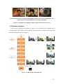
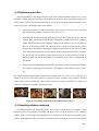
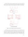
A result example of the three aforementioned approaches can be observed in the following
pictures, which simulate these procedures. It is important to realize, that the example has
deliberately been chosen to confine the important information in a relatively small, not centric area.
a) Original image
b) Downsampled image
c) Cropped image with and without prior semantic analysis (Semantic vs blind cropping)
- 10 -
d) Keyframes in manual browsing or in automated Image2Video
Figure 2-2: Comparison between the different existing approaches
2.3 Attention focus detection
As already mentioned before, the Image2Video application relies on the external image
analysis and ROI generation, separating clearly the image analysis from the ROI based content
adaptation. To underline this fact, from now on we’ll divide the Image2Video application into
ROIExtraction plus ROIs2Video (video generation out of an input image and a set of ROIs), being
this work centered in the ROIs2Video development.
The transmoding tool is focused mainly on the video generation, independently on the
generation of semantic values of the ROIs. This way, any external program can use a desired object
detector and pass the ROI specification file to the ROIs2Video algorithm.
In the deployment of the Image2Video CAT (Content Adaptation Tool) for the aceMedia
project, the workpackage WP4 (D4.2 and D4.7 deliverables) provides an attention object detector
that is scoped to person and face detection/recognition [5]. Other applications, like surveillance
systems, could use the ROIs2Video algorithm adding for example a detector for any specific object
(for example: cars, trains, abandoned objects…), generate a video using the analysis data and send
the video over to a mobile device carried by a security guard.
Generally, for most common applications, the semantic analysis is based on face and text,
because most visual attention models (see [1] [3] [9] [10]) state that these are the objects an
average viewer concentrates on in entertainment applications.
The following sections will therefore offer a brief introduction into the used detection
algorithms for faces.
2.3.1 The Viola-Jones face detection method
The Viola-Jones method for face detection (available in OpenCV –see Appendix D-), proposed
by Paul Viola and Michael Jones [12], is based on the training of a classifier with positive and
negative examples.
- 11 -
2.3.1.1 Features
This classifier uses simple rectangular features evolved from Haar wavelets (pairs of dark and
light rectangles), thus called Haarlike features. Three different kinds of features are used:
Two-rectangle features: The value of a two rectangle feature is the difference between the
sums of the pixels in each rectangular region. The rectangles can be horizontally or
vertically adjacent and have to be the same size (Figure 2-3 a.).
Three-rectangle features: The value of such a feature is the sum of the pixels in the outside
rectangles minus the sum of the pixels in the center rectangle. (Figure 2-3 b.)
Four-rectangle features: The value is computed as the difference between diagonal pairs of
rectangles as shown in Figure 2-3 c
a. Two-rectangle feature
b. Three-rectangle feature
c. Four-rectangle feature
d. Weak classifiers
Figure 2-3: Example rectangle features
The base resolution of the detector is 24 x 24 pixels, which tends to the smallest window that
can be used without losing important information.
- 12 -
For the calculation of the rectangle features, an intermediate representation for the image – the
integral image ii – is used:
ii ( x, y ) =
∑ pixels = ii( x
∑ i( x' , y ' )
4
, y 4 ) − ii ( x 2 , y 2 ) −
D
− ii( x3 , y 3 ) + ii ( x1 , y1 )
x '≤ x , y '≤ y
a) The value of the integral image at point b) Calculating the rectangular sum using
(x,y)
the integral image
Figure 2-4: Integral image
Using the integral image, the rectangular sum of pixels can be calculated in four steps (see
Figure 2-4 b.).
2.3.1.2 AdaBoost machine learning method
Using the rectangular features and a set of positive and negative examples, a classification
function can be learned. There are 160.000 rectangles associated with each image sub-window.
Each feature can be computed efficiently, but computing the entire set is completely unfeasible. In
the Viola-Jones classifier, a variant of AdaBoost [13], short for Adaptive Boosting, is used to select
the features and to train the classifier.
AdaBoost combines many weak classifiers in order to create a strong classifier. Each weak
classifier finds the right answer only a bit better than 50% of the times (almost a random decisor).
The final strong classifier is a weighted combination of the weak classifiers, being the weights
distributed initially uniformly and then re-weighted more heavily for the incorrect classifications as
shown in Figure 2-5.
- 13 -
Figure 2-5: 1. Initially, uniform weights are distributed through the training examples.
2&3. Incorrect classifications are reassigned with more weight (shown as bigger dots).
The final classifier is a weighted combination of the weak classifiers
Viola and Jones combine weak classifiers as a filter chain (see Figure 2-6), where each weak
classifier consists of a single feature. The threshold for each filter is set low enough to pass almost
all the face examples. If a weak classifier filters a subwindow, the subwindow is immediately
tagged as “no face”.
Figure 2-6: The classifier cascade is a chain of single-feature filters
2.3.1.3 Scanning an image
To search the object across the image after the training, a search window scans the image
looking for the object. As the object does not have to be of the same size as the trained examples,
the search window (not the image itself) has to be resized and the procedure repeated several times.
2.3.1.4 Detection results and general comments
The Viola-Jones classifier was used at the beginning of the Image2Video application’s
development in order to have automatical ROI annotation and not have to annotate the ROIs
manually. The face detector does not detect 100% of the faces, especially not when the head is
turned or a part of the face covered by something. What is more annoying for the Image2Video
application is that the Viola-Jones face detector frequently classifies erroneously parts in images as
faces, that really are not. When the simulated camera stops at these parts of the image the viewer
gets confused.
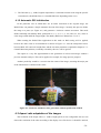
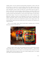
The following figures are examples of real executions of the Viola-Jones face detector using
the trained data from the file haarcascade_frontalface_alt.xml.
- 14 -
a) 4 detected faces, 1 not detected face, 3 erroneously detected faces
b) 2 detected faces, 4 not detected faces, 0 erroneously detected faces
- 15 -
c) 3 detected faces, 0 not detected faces, 6 erroneously detected faces
Figure 2-7: Performance of the Viola-Jones detector
Just out of curiousity, the Viola-Jones seems to be the first real-time frontal faces detector
system running at 15 frames per second on a conventional PC. OpenCV provides the code for
testing this system with a webcam and it works fairly well, although it sometimes detects parts of
the background as faces.
The Viola-Jones algorithm can be adapted to detect other objects, for example hand detection,
which has been implemented at the University of Ottawa changing the training data and haarlike
features.
2.3.2 Face detection in aceMedia: the Convolutional Face Finder
Face detection in aceMedia is based on Cristophe Garcia and Manolis Delakis’ Neural
Architecture for Fast and Robust Face Detection [7]. Using the Convolutional Neural Network,
called Convolutional Face Finder in this article, this research line aims to achieve high detection
rates with a low rate of false positives, even in difficult test sets with faces that can be rotated ±20
degrees in image plane and turned up ±60 degrees.
2.3.2.1 Convolutional Neural Network Architecture
The Convolutional Face Finder consists of six layers plus the retina that receives a matrix of
32x36 pixels that wants to be classified as face or non-face (see Figure 2-8). The layers are divided
into two alternated Ci and Si layers and finally followed by two Ni layers:
- 16 -
The Ci layers are convolution layers, responsible for detecting face features.
The Si layers follow the Ci layers and reduce the precision of the position in the feature
map, because only the approximate, relative position of the features in a face is
important.
The Ni layers contain classical neural networks and decide the final classification,
based on the extracted features in the previous layers.
Figure 2-8: The Convolutional Face Finder (Image copied from [7])
2.3.2.2 Training the parameters
Each layer has trainable coefficients for extracting and classifying the features:
C1: 104 trainable parameters
S1: 8 trainable parameters
C2: 194 trainable parameters
S2: 28 trainable parameters
- 17 -
N1: 602 trainable parameters
N2: 15 trainable parameters
These parameters are trained with a set of 3702 different face areas, showing faces in
uncontrolled natural environments. The faces are manually annotated to indicate the eyes and
mouth positions and cropped to the 32x36 pixel size of the retina. The faces passed to the retina
deliberately include the borders of the face, because the system is fed with more information and
thus will reduce the false positives. Note that the size of the retina is bigger than the size of the
images in the Viola-Jones method (24x24 pixels).
The parameters also want to be trained with non-face images, what is more difficult, as any
random 32x36 image not containing a face can be used as a non-face example. Therefore the
bootstrapping algorithm is used, that trains the system with false positives found in a set of 6422
non-face images and retraining the system.
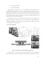
2.3.2.3 Face localization
Figure 2-9: Steps in face localization (Image copied from [7])
As seen in Figure 2-9, in order to find the faces with resolution close to 32x36, a multiscaled
pyramid of the image is created. For each image in the pyramid, the Convolutional Face Finder is
- 18 -
applied, resulting in a set of face candidates in the original scaled image. Finally a neural filter is
applied to the fine pyramid centered at the candidates and, depending on the percentage of positive
answers each candidate is classified as Face or Non-face.
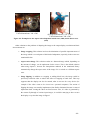
2.3.2.4 Detection results
a) 5 detected faces, 0 not detected faces, 0 erroneously detected faces
b) 6 detected faces, 0 not detected faces, 1 erroneously detected faces
- 19 -
c) 3 detected faces, 0 not detected faces, 0 erroneously detected faces
Figure 2-10: Performance of the Convolutional Face Finder
2.4 Existing Image2Video approaches
In this chapter former Image2Video applications will be presented and compared. Principally, there
are three existent approaches, omitting other applications that basically generate video slideshows
adding special effects, soundtracks etc. (such as for example Microsoft’s Photostory (see Figure
2-11)).
Figure 2-11: Microsoft’s Photostory initial dialog
- 20 -
2.4.1 Image2Video adaptation system - IST Lisbon
This project [1] has been led at the Instituto de Telecomunicações in Lisbon by Professor
Pereira and two of his students, Baltazar and Pinho. The developed application appears to be an
alternative implementation of the described in Liu et al’s article [9], discussed in the next section.
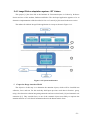
The authors divide their Image2Video application in 4 steps as shown in Figure 2-12.
Figure 2-12: System architecture
1. Composite Image Attention Model
The objective of this step is to determine the attention objects, which will be classified into
saliencies, faces and text. For this task they build upon previous work done in Pereira’s group,
using a face detection solution integrating automatic and user assisted tools [14] and automatic text
extraction [15]. They consider faces as one of the semantic objects most likely to captivate the
attention and text as a rich font of information that ties the human mind’s focus.
- 21 -
2. Attention model integration
Step 2 is an integration stage, where the authors pretend to create a unique attention map using
the previously identified attention objects and solving the possible spatial overlappings. The criteria
are:
Face-Text integration: Faces and text have completely different semantic values and should
therefore not be integrated together. The authors state that the cases where text and faces
overlap are due to inexact definitions of the bounding boxes of the detected ROIs.
Face-Saliency integration: A detected face and a detected saliency are most likely to
represent the same ROI, a face, if the face contains a significant part of the saliency. This
condition can be expressed as:
area ( ROI face ∩ ROI saliency )
area ( ROI saliency )
≥ 0.25
Text-Saliency integration: Equivalently, a detected text and a detected saliency are most
likely to represent the same ROI if
area ( ROI text ∩ ROI saliency )
area( ROI saliency )
≥ 0.25
Besides the integration of different detected attention objects, in this stage the authors also
assign the order of importance of the attention objects: the attention values. The type of attention
object implicates a certain weight:
WSaliency=0.2
WText=0.35
WFace=0.45
According to their experiments, the attention value AVi of each object is modified according to
the weight of the type:
AV final = AV ⋅ Wm
Attention objects with a final AV that falls under a certain threshold will be eliminated, while
AOs with higher AVs will enjoy higher priorities in the next stages.
3. Optimal Path Generation
In this stage, the path used to display the video will be generated in two steps:
- 22 -
i.
Display size adaptation: The attention objects ideally want to be displayed in the video with
the same spatial resolution as the image (i.e. one pixel on the image wants to be displayed
as one pixel on the video). Therefore, big attention objects (except faces) have to be split in
smaller parts that fit the display size. Small attention objects can ocassionally be grouped
with others.
ii.
Browsing Path Generation: This mechanism determines the order in which the attention
objects will be displayed. Attention objects are displayed following the order of their AVs
and taking into account the travelled distance somehow in order to avoid travelling back
and forth. However, this algorithm is not explained in detail and lacks clarity.
4. Video Generation
In this stage the video sequence is generated according to three modes:
i.
Normal mode: All the attention objects are shown
ii.
Time based mode: The video cuts all the attention objects that appear after a certain time
limit.
iii.
Amount of information based mode: The video sequence will show only the most
important attention objects until a certain information percentage limit is reached.
2.4.2 Rapid Serial Visual Presentation – Microsoft Research Asia
Microsoft Research Asia has published a variety of articles principally under the authory of
Xie, Ma and Zhang [9] [10], which use the exact term Rapid Serial Visual Presentation for the
result output of their system. The Rapid Serial Visual Presentation can be regarded as a type of
video which displays serially the different parts of the image, each for a short period of time and
scrolls between the regions, though it is not saved as a proper video file.
The Image2Video system developed at the IST, presented in the previous chapter, clearly is
built upon the ideas presented in these articles. The similarity between both system architectures
results evident when comparing both frameworks (see Figure 2-12 and Figure 2-13). Thus, this
section will only comment briefly some the Rapid Serial Visual Presentation, omitting details.
In the articles Xie, Ma and Zhang focus on the description of the browsing path generation and
leave the image modeling stages (attention object detection) apart. The authors distinguish between
the fixation status, in which a particular ROI is exploited, and the shifting status, where the
presentation shifts between one ROI and the next one. The shifting between two ROIs is simulated
by traveling the straight lines that link the attention objects and never exceeding maximal panning
or zooming speeds.
- 23 -
Figure 2-13: System architecture
1. Preprocessing the ROIs
In order to find the optimal path, it is essential to preprocess the ROIs:
splitting attention objects larger than the screen size
grouping together nearby attention objects to reduce the computational complexity of the
browsing path generation algorithms
2. Optimal Path Generation
Similar to the time based and information based modes in the IST’s Image2Video application,
Xie and his colleagues define the Skimming and the Perusing mode, which obtain the order of the
ROIs using a backtracking algorithm to enumerate the possible paths and find the best among them.
In the case the user wants to view all the information, the problem of ordering the ROIs can be seen
as the Traveling Salesman Problem and an approximation algorithm can be applied to find a fast
but suboptimal solution.
- 24 -
3. Dynamic Path Adjusting
The system also allows the user to stop the browsing process, look at the image independently
and resume the automatic presentation afterwards.
2.4.3 Photo2Video – Microsoft Research Asia
The Photo2Video method [3] appears to be Microsoft Research Asia’s evolution of the Rapid
Serial Visual Presentation, including many new features and options. From the presented systems,
it appears to be by far the leading system with the most evolved characteristics. It aims to be more
than just a simple transmoding tool, and targets the capacity of generating musical stories out of
image series. The general system’s flowchart, designed to succeed such features, is presented in
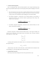
Figure 2-14 and the detailed description of the stages will be included next.
Figure 2-14: Flowchart of Photo2Video taken from [3]
1. Content Analysis
The content analysis applies a set of image and music content analysis algorithms.
i.
Image analysis: The images are first ordered by timestamps if available and by filenames
otherwise. The images are passed through a quality filter that removes images with a
quality measure under a predefined threshold and through a duplicate detection filter that
removes similar photographs.
- 25 -
Next, face and attention detection are applied to estimate the attention objects on each
specific image and thus to establish the ROIs. The face detection can be accompanied by
some external annotation in order to be able to generate a film for an individual person out
of a digital photo album.
With the information gathered during the face and attention detection, each photograph can
be semantically classified into different established groups, such as no-people, portrait,
multiple people, group photograph…
ii.
Music analysis: The video presentation will be accompanied by incidental, synchronized
music. The functioning of the alignment between music and video will not be described in
this document.
2. Story Generation
As the name already anticipates, this stage attempts to generate a story line based on generating
Temporal Structure Layers. It is completed in three steps:
i.
Photograph selection and grouping
ii.
Specify leading actor
iii.
Advanced Story Generation, where the user is able to interact, undo previous automatic
actions, provide scene titles and impose some other desires.
The result of this stage is a group of XML files representing a timeline and the moments each
specific action starts and ends.
3. Framing scheme
The framing scheme is divided in Key-frame Extraction, Key-frame Sequencing and Motion
Generation.
The Key-frame Extraction defines the origin and destination frames of the simulated camera
movement, in order to generate smooth motions. The authors define different types of frames,
classificating them by the area of the picture they include: Full, medium and close-up frames
The Key-frame Sequencing will establish the order in which these extracted key-frames are
presented (for example Full frame Medium frame Close-up frame).
Finally, the Motion Generation step is in charge to simulate the virtual camera movement
between the key-frames with the principal target of generating a smooth motion. The necessary
controls needed for this task are:
- 26 -
•
Panning Motion Trajectories: The trajectories will be generated by cubic interpolating
splines with the smallest maximal curvature.
•
Speed Control: Determining the average speed control, the local panning speed control
and the local zooming speed control
The output of this step is the video information that is added to the music file, in order to
generate the complete, composed video.
2.4.4 Conclusions
2.4.4.1 Differences between the Image2Video approaches
The presented articles have shown a general insight into the existing Image2Video
applications. As anticipated before, the Photo2Video application seems to be the most advanced
application in image to video transmoding, presenting the most extense prior processing and
explaining in detail the followed algorithms to generate the simulated camera motion.
IST’s approach does not include striking new features and seems to be an alternative
implementation of Microsofts Rapid Serial Visual Presentation (as far as the articles show). Both
articles present a similar previous semantic analysis of the image, the same preprocessing of the
detected ROIs and finally present a similar browsing path generation. Both articles don’t mention
how to generate the simulated camera motion, how they interpolate the curves or how they control
the speed of the movement. This leads to think that they haven’t focused their work on these
aspects, but have concentrated on the ROI generation and processing (grouping, splitting...). The
Time Based and Amount of Information Based (or Perusing and Skimming mode) video
generations don’t appear to be very useful or optimal solutions, as a certain amount of information
can be cut of the video almost randomly.
Microsoft’s Photo2Video application, on the contrary, is a more complete article. The approach
is an entertainment application to generate video-albums with incidental music to be viewed on a
personal computer, and therefore needs a strong content analysis, semantic classification and story
generation, in order to generate meaningful video albums. This information processing is useful for
leisure-time applications, but unnecessary for other particular uses, such as security and
surveillance systems. A difference to the other approaches is that the Photo2Video application is
not designed to generate small sized videos for mobile devices and does not talk explicitly about
the possibility of adapting the video to different screen sizes. The motion generation is discussed in
detail and has served as a guide for some of the decisions taken for the work of this master thesis.
- 27 -
2.4.4.2 Contributions of this master thesis
Our approach will rely on an external information source that establishes the ROIs that have to
be shown and assigns an importance or relevance (both terms will be used indistinctly) factor to
each ROI so it is displayed proportionally to its relevance. All the applications presented above
include fixed ROIExtraction modules (i.e. face and saliency detectors) and differentiate the
presentation according to the ROI type. Our work pretends to be a more general approach for the
ROIs2Video system and to concentrate on a quality, user customizable video generation that can be
generated independently on the prior semantic analysis. The planned contributions in the research
field of Image2Video adaptation are:
Video quality and motion smoothness
General and open implementation, independent on the prior ROI detection and semantic
analysis.
User customizable video. The user can set his preferences in:
•
Camera motion speed
•
Curvature of the camera motion
•
Maximal zoom-in
•
Video bitrate and used codec. This options offer the possibility of generating lighter or
heavier videos, leaving it to the user to find a compromise between the video coding
quality and its size. For example if the video will be sent through a low-bandwith
network the user is able to generate a video with low bitrate.
Possibility of using automatic or manual methods:
•
Automatic or manual ordering of the browsing path.
•
Using the manual annotation GUI, together with the manual ordering and the other
available options, is a powerful and fast tool to create completely personalized videos
Video generation at any frame resolution, as long as the resolution is lower than the image
resolution.
New research in alternative algorithms to the ones used in the articles.
- 28 -
3 Design
3.1 Definitions
Before starting describing the architecture, it is important to establish some definitions to avoid
misunderstandings and unify some concepts.
Window/Sampling window: Rectangle of pixels copied from the original image. It is the
part of the original image captured by the virtual camera (see Figure 3-1 a).
Frame: The sampling window that travels through the original image is resized to the
video dimensions and constitutes a frame of the generated video (see Figure 3-1 b). The
video will show 25 frames per second.
Keyframe: Frame of special interest where the camera movement is stopped. For example
that frames corresponding to the ROIs’ locations.
ROI or attention object: Both terms are used sometimes indistinctively, although the
definition of attention object denotes more information (minimum perceptible time and
size, attention value, etc.). A ROI is the spatial region occupied by the attention object. In
this text, both terms are used to designate the regions where most semantic information is
concentrated in the image and where the sampling window has to centre to extract the
keyframes (see Figure 3-1 a).
a) ROIs and sampling windows centered on the ROIs
- 29 -
b) Frames generated by resizing all the sampling windows to the video’s dimensions. The
frames shown are the keyframes corresponding to the ROIs
Figure 3-1: Examples for sampling windows, ROIs and frames on a picture
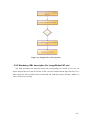
3.2 System overview
In this section a general block diagram (see Figure 3-2) of the ROIs2Video algorithm and an
overall description of each point will be presented. The specific tasks to complete at each point will
be detailed individually in future chapters.
Figure 3-2: ROIs2Video algorithm steps.
- 30 -
1.
ROI initialization: Read out the ROI descriptions from the specified file or create an
automatic set of ROIs in case of generating a video preview of a photo.
2.
Image adaptation: Read the input image and adapt it to the aspect ratio of the video
dimensions. The ROIs may have to be relocated.
3.
Keyframe extraction: Selection of the key positions for the sampling window.
4.
Sampling Window Centring: Place the sampling windows trying to centre the ROIs.
5.
Optimal path calculation: Apply sorting criteria to find a pleasant and coherent order
for flying through the keyframes.
6.
Camera motion speed control: Camera motion speed calculation based on the original
image size, experimental observations and on the user’s preferences.
7.
Curve interpolation: Calculate an interpolated curve that joins the data points given by
the keyframes and apply speed control to the curve.
8.
Camera simulation: Travel the Catmull-Rom curve, saving the sampling windows as
equally sized image files, which will constitute the frames of the video. The saved
images will then be converted and coded to video with Ffmpeg libraries4. The video
generation will allow certain flexibility in relation to the video characteristics, such as
bitrate, codec or resolution.
3.3 Internal data structures
3.3.1 Image structure
The structure used for loading and dealing with an image is the IplImage structure, delivered in
the OpenCV library and that presents following fields:
typedef struct _IplImage
{
int nSize;
/* sizeof(IplImage) */
int nChannels;
/* Most of OpenCV functions support 1,2,3 or 4
channels */
int depth;
/* pixel depth in bits: IPL_DEPTH_8U,
IPL_DEPTH_8S, IPL_DEPTH_16U,IPL_DEPTH_16S,
IPL_DEPTH_32S, IPL_DEPTH_32F and IPL_DEPTH_64F
are supported */
int dataOrder;
/* 0 - interleaved color channels,
1 - separate color channels.
cvCreateImage can only create interleaved
images */
4
http://ffmpeg.mplayerhq.hu/
- 31 -
int
origin;
int
int
int
width;
height;
imageSize;
char *imageData;
int widthStep;
/* 0 - top-left origin,
1 - bottom-left origin (Windows bitmaps style)
*/
/* image width in pixels */
/* image height in pixels */
/* image data size in bytes
(=image->height*image->widthStep
in case of interleaved data)*/
/* pointer to aligned image data */
/* size of aligned image row in bytes */
}IplImage;
Note: Fields irrelevant for this work have been omitted for space reasons
3.3.2 ROI structure
The structure to manipulate ROI information will present the following fields:
typedef struct Roi{
CvRect *rectangle;
CvPoint *ul_point;
CvPoint *lr_point;
int importance;
//The rectangle representing the spatial
Location of the ROI
/*The upper-left point of the sampling
window that centers the ROI*/
/*The lower-right point of the sampling
window that centers the ROI*/
//Displaying-time factor
}Roi;
3.3.3 Trajectory structure
A variable of the type Trayectory will store the interpolated points that link one keyframe to the
following one.
typedef struct Trayectory{
int n;
double ul_distance;
double lr_distance;
CvPoint *curve;
//Number of points in the array curve
/*Distance the upper-left corner will
travel in this trajectory*/
/*Distance the lower-right corner will
travel in this trajectory*/
/*Array of interpolated points that
conform a trajectory*/
} Trayectory;
3.4 ROI specification files
As already mentioned in chapter 2.3, the ROIs2Video application relies on the external image
analysis and attention object model generation. This work is focused mainly on the video
generation, independently on the semantic values of the regions of interest and therefore will define
a structure for the ROI specification file, which has to be respected by any possible external
- 32 -
detector. The file will be read out and stored into the ROI structures presented in 3.3.2. The file will
be written in XML format, and will have to contain a numbered node <ROIx> for each ROI.
Nested in the <ROIx> node, the information for the coordinates (x,y) for the upper-left corner, the
width, height and the relevance of the ROI have to be found like shown in the following example
The meaning of the first four tokens (x, y, width, and height) is cleared in Figure 3-3.
Figure 3-3: Specification of a ROI
The meaning of the Importance token is the importance of the ROI and will be explained later
(see chapter 4.8).
- 33 -
The read-out of the xml file will be done using the available file storage functions in OpenCV.
This is the reason why the root node obligatorily has to be tagged with <opencv_storage>.
Alternatively, if no ROIs want to be defined, the application has to present a mode that
generates a basic video preview of the image. This mode will be detailed in chapter 4.1.2.
The XML file will not follow MPEG standards, because this would imply heavier labeling but
could be desirable for a 100%MPEG compliant application.
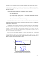
3.5 Zooming and shrinking images
During the generation of the output video, it is necessary to oversample (zoom) or undersample
(shrink) images, when adapting sampling windows to frames [16]. Zooming requires the creation
and assignment of values to new pixels. The easiest and fastest method is the Nearest Neighbour
interpolation, which tends to replicate the nearest pixel. A special case of the Nearest Neighbour
interpolation is in fact the Pixel Replication, applicable when the size of an image wants to be
increased an integer number of times. Each column is replicated n times and then each row is
replicated n times. Although the method is fast, it produces pixelation (checkerboard effect) for
high factors.
Figure 3-4: Comparison of the performance of the different interpolation methods. From left
to right and up to down, we have the original image, the interpolated image using NN
interpolation, using bilinear interpolation and bicubic interpolation. The images have been
generated shrinking the original image to a resolution of 50x50 pixels and then zooming in to
a resolution of 1200x1200.
- 34 -
A slightly more sophisticated way of zooming images is the bilinear interpolation, applied in
the ROIs2Video tool, and which uses the average of the four nearest neighbours of a point.
Other interpolation methods, as for example the bicubic interpolation, use more neighbour
points to obtain the interpolated value. This generally provides better and smoother results, but is
also computationally more demanding. In the ROIs2Video application, it does not seem to be
useful to apply a complex method and it is preferable to use the bilinear interpolation to reduce
processing time.
The CvReference library (see Appendix D) in OpenCV includes the needed methods, so the
digital image interpolation has not to be implemented from scratch.
- 35 -
4 Development
4.1 ROI initialization
4.1.1 ROI initialization from file
The first attempt of defining the ROI specification files was a simple text file, which contained
each ROI specified in a separate line in the form
XROI1 YROI1 WidthROI1 HeightROI1 RelevanceROI1
XROI2 YROI2 WidthROI2 HeightROI2 RelevanceROI2
…
...
The final solution tries to take advantage of XML’s robustness. The mandatory structure of the
XML files was described in section 3.4. The read-out of these files is done using OpenCVs file
storage functions, which provide a complete set of access functions to XML files. The following is
an example of an actual XML file with two ROIs.
<?xml version="1.0"?>
<opencv_storage>
<ROI1>
<x> 988 </x>
<y> 454 </y>
<width> 347 </width>
<height> 433 </height>
<importance> 1 </importance>
</ROI1>
<ROI2>
<x> 986 </x>
<y> 961 </y>
<width> 389 </width>
<height> 569 </height>
<importance> 1 </importance>
</ROI2>
</opencv_storage>
When opening the XML file, OpenCV automatically controls the integrity of the XML file and
checks that some necessary nodes are included. The XML files have to start with the declaration of
the xml version and the root node has to be tagged as <opencv_storage>.
The next step is to read each ROI and insert it into a CvSeq sequence, where all the ROIs will
be stored and returned. Each ROI is tagged with <ROIx>, where x is an increasing counter. The
data of each ROI is retrieved in two steps:
1. The file node containing the requested data is found using the cvGetFileNodeByName, that
returns the map of a particular node
- 37 -
2. The ROI data (x, y, width, height & importance) is extracted from the node using the specific
read method (cvReadIntByName or cvReadRealByName depending on the case).
4.1.2 Automatic ROI initialization
In the particular case in which there are no ROIs associated to the original image, the
ROIs2Video can generate a simple automatic division of the image. Currently, this process divides
the image in 4 parts (see Figure 4-1) and generates a clockwise camera movement. This mode
defines internally four dummy ROIs, positioned at (1, 1), (w/2, 1), (1, h/2) and (w/2, h/2), where w
is the image width and h the image height. The dummy ROIs have dimensions w/2 x h/2.
When running the ROIs2Video application in this mode no ROI sorting will be applied,
because the order wants to be maintained as shown in Figure 4-1. Also the interpolated curves
between ROIs will consist of straight lines and the curvature parameter (explained in chapter 4.7.2Catmull-Rom interpolation), eventually selected by the user, will be ignored.
This option is a very first approximation to the generation of videos from images without a
previous semantic analysis. This can be applied, for example, for image preview purposes.
Another possibility would be a zoom-in into the centre of the image, assuming the major part
of the information is confined in the centre.
Figure 4-1: Clockwise automatic video generation without specification of ROIs
4.2 Aspect ratio adaptation of the images
The resolution of the output video (i.e. width x height pixels) is user configurable: the user can
choose the resolution of the video according to the display size of his device. It should be noticed,
- 38 -
that if the selected video resolution and the original image do not have the same aspect ratio, it is
necessary to adapt the image to the screen by adding black horizontal or vertical bars. When adding
the bars, the positions of the ROIs have to be adequately displaced the same number of pixels of
the black bars’ size.
The size in pixels of each black bar is calculated
-
in case of upper and lower bars as:
hbar
-
h
wimage × video
wvideo
=
2
− himage
in case of left and right bars as:
wbar
w
himage × video
hvideo
=
2
− wimage
Adding the bars can be more or less noticeable, depending on the aspect ratios of the video and
the image. The worst case is when a horizontal/vertical image wants to be transmoded to a
vertical/horizontal video (see Figure 4-2). Though, the decision of adding bars produces less sideeffects than other adaptation solutions, and what is more important, avoids information loss.
a) Image dimensions: 2304 x 1728
Video dimensions: 240 x 300
b) Image dimensions: 1232 x 1632
Video dimensions: 300 x 240
- 39 -
c) Image dimensions: 2304 x 1728
Video dimensions: 300 x 240
d) Image dimensions: 1232 x 1632
Video dimensions: 300 x 240
Figure 4-2: Examples for the aspect ratio adaptation in bad cases (a&b) and in better cases
(c&d)
Other solutions to the problem of adapting the image to the output display resolution and their
inconvenients are:
•
Image cropping: This solution involves the elimination of possible important areas of
the image which is a weak point of this kind of adaptation, especially in the worst case
mentioned before.
•
Aspect ratio change: This solution results in a distorted image which, depending on
the amount of change, can be unpleasant for the viewer. This is the default solution
when using OpenCV, because the interpolation methods in the mentioned library
automatically change the aspect ratio of the image if it is resized to a different aspect
ratio.
•
Image flipping: In addition to cropping or adding black bars, the image could be
previously rotated in order to reduce the effect of cropping or black bars. This step
supposes that the display can also be rotated, what is not true for every device (for
example if the video wants to be viewed on a personal computer). The action of
flipping the image was actually implemented, but finally eliminated because it seemed
unpleasant when viewing the videos on fixed screens. Also, if a video is generated by
the camera fly-through of various input images, it would be annoying to have to turn
the display every time the image is flipped.
- 40 -
4.3 Finding the optimal browsing path
4.3.1 Jumping to the nearest unvisited ROI
The first attempt to establish the order of presentation of the ROIs was to start by the ROI
situated most to the left and then continue jumping to the closest, still not displayed ROI and so on.
For a very reduced number of ROIs (<5), or specific cases where the ROIs where placed following
certain patterns (for example all ROIs placed in a row), this method showed up coherent browsing
paths. However, when the number of ROIs increased, this fairly simple algorithm reduced
drastically the quality of the browsing paths, returning chaotic browsing paths with back and forth
movements. The solution of finding a good browsing path had to be found in some other way.
4.3.2 Simulated Annealing
The optimal browsing path will be obtained using a Simulated Annealing [17] approach, which
will return a sorted array of ROIs with a path-distance near to the optimum. The algorithm imitates
the process of metallurgic cooling of a material to increase the size of its crystals and reduce their
defects. This technique is often used to solve the Travelling Salesman Problem5 finding a good path
for the salesman, who wishes to visit a certain set of cities travelling the shortest distance possible.
If the number of cities to travel is big, this problem can not be solved by brute force in an
affordable amount of time.
Simulated annealing usually locates a good approximation to the global optimum of the
browsing path. Each step in the simulated annealing process replaces the actual solution by a
random nearby solution (i.e. exchanging two nodes of the browsing path). If the new solution has a
lower cost, it is chosen; if the new solution shows up to have a worse cost, it can be chosen with a
probability that depends on the worsening and on the ‘temperature’ parameter, that is gradually
decreased during the process imitating the cooling process of metals. At the beginning of the
process, when the temperature is high, more changes will be admitted, while worse changes will be
admitted more seldom when the temperature is cold at the end of the process. The allowance for
“uphill” moves saves the method from becoming stuck at local minima.
As the trained eye might have noticed, it is important to define the appropriate cooling ratio. If
we define a high rate of temperature decrease, the algorithm will take less time, but probably will
find a relatively bad solution. On the other hand, a very slow cooling schedule will find solutions
near to the optimal with higher probability, but will take more processing time. Therefore it is
5
http://www.tsp.gatech.edu
http://en.wikipedia.org/wiki/Simulated_annealing
- 41 -
necessary to find a compromise between computing time and the actual quality of the solution. In
our particular case, the path has to be as short as possible, because a longer path will mean less
comfort in the viewing of the output video, as the simulated camera will move back and forth
through a strange path.
The simulated annealing algorithm has a strong random character, marked by:
•
The initial random path.
•
The defined exchange function, which in our particular implementation exchanges
fortuitously two nodes of the path.
•
The acceptation function for unfavourable exchanges.
This random character has as a consequence that two executions of the same data set will most
probably have different solutions, especially when the set of data points grows. The actual quality
of the solutions is hard to predict.
This approach works much better than elementary browsing path generations (for example our
first implementation of jumping to the next unvisited ROI) and generally shows good results,
especially in pictures that contain a moderate number of ROIs (<15). For pictures with many
attention objects (e.g. group photos), the path generated by this algorithm is acceptable in most of
the cases, but sometimes it could be improved.
Figure 4-3 shows two different simulations of camera path generation with the Simulated
Annealing algorithm using the same parameters. Each one shows a plot of the cost function
evolution along the iterations and a plot of the obtained path through all the cities (in this case the
ROIs) showing the random character of this algorithm.
200
Cost
150
100
50
0
20
40
60
Iterations
80
100
120
0
1
21
14 13 9
10
8
11
6 7
12
2
y
4
20 2
15
6
19 16
8
10
18 17 3
-5
0
4
5
5
10
15
20
x
a) Simulation example with a relatively bad path found
- 42 -
200
Cost
150
100
50
0
20
40
60
80
Iterations
100
120
140
0
1
2
19 18 16 15
3
21 20
5
4
6
7
2
y
4
17
14
1112
13
6
8
10
-5
0
8
9
5
10
10
15
20
x
b) Simulation example with a good path found
Figure 4-3: Two simulation examples of the Simulated Annealing with a random set of data
points
The advantages a good browsing path shows up are:
Shorter and therefore smaller sized videos.
Reduction of the processing time to generate the video.
More pleasant video watching sensations as a short browsing path will implicitly
reduce the number of camera zigzag movements.
The pseudocode of the simulated annealing algorithm looks as follows:
Initialize i0, c0, L0;
k=0;
i=i0;
repeat
for l=1 to Lk
generate jЄS
if f(j)<=f(i) i=j;
else if exp((f(i)-f(j))/ck)>rand[0,1] i=j;
k=k+1;
ck=ck x α
until final condition;
i: actual browsing path
j: possible next browsing path
ck: temperature variable
c0: initial temperature
Lk: iterations in each step
f(i): cost function of path i
α: cooling parameter (0.8<α<0.99999)
- 43 -
4.4 Keyframe extraction
The specified ROIs, or the image divisions in the video without semantic analysis, act as video
keyframes. Additionally, the full image will be added as a keyframe at the beginning and at the end
of the video in order to give an initial and final overview of the complete image and let the viewer
locate every object. The detailed steps are as follows:
•
The video will start off with the full image (first keyframe) and will zoom in towards
the first ROI. This pattern is called forward sentence [3].
•
Following the obtained browsing path, the video will show consecutively the different
defined ROIs, connecting them through Catmull-Rom interpolation curves (shifting
mode). The dimensions of the sampling window on the picture will vary and adapt to
the size of the displayed ROI. The captured picture will be converted into the videosized frame using bilinear interpolation. Bilinear interpolation is used instead of other
more elaborate interpolations (as for example bicubic interpolation) because it requires
less processing time and delivers good enough results for a video where each frame is
displayed 40ms and where the human eye’s limitations won’t allow to distinguish so
fine details.
•
After having travelled through all the ROIs, the virtual camera will zoom out and show
the complete image again (last keyframe). This pattern is called the backward sentence
[3].
The forward and backward sentence patterns form together the ring sentence [3]. Using the ring
sentence, the viewer of the video perceives a general overview of where every element is situated
in the image, before and after the virtual camera zooms in to offer a detailed view. Figure 4-4
shows the keyframes associated to a particular image.
Figure 4-4: Examples of keyframes in a ROIs2video sequence
4.5 Sampling window centering
As explained before, the keyframes of the video will be constituted by the complete image
followed by the set of regions of interest. The ROIs will be centred perfectly in the sampling
window. Other similar Image2Video applications [1] centre faces on the upper third portion of the
window, stating that the body below the face attracts the user’s attention. In our case the specific
- 44 -
type of each ROI is not defined, as the implementation is independent of the ROI types, and
therefore this kind of case is not taken into account. Exceptionally, when the ROI is next to an
image border, the window can’t centre the attention object and will be situated at the border(s) of
the image.
When centring the ROI in the sampling window, it is necessary to decide:
•
How to show objects of a size bigger than the display size (in pixels).
•
Up to which zooming factor small attention objects will be shown in the video (see
section 2.1.2for ‘minimal perceptible size’ concept definition).
In the first implementation of the Image2Video CAT, the video displays the defined ROIs in
their original size if the ROI’s size is smaller than the output video resolution (spatial scale 1:1) or
in the biggest possible size if the ROIs’ dimensions are greater than the output video resolution,
obtaining a ROI which occupies the whole video screen.
In the actual version, the user can set the maximal zooming factor he wants to apply to small
ROIs. This way, the presentation size of a ROI is limited either by the maximal zooming factor or
by the video resolution. When setting the zooming factor, the user has to be aware that if the ROI is
zoomed in excessively, the corresponding frames generated through bilinear interpolation will lose
resolution and quality. It will be left to the user to establish his preferences and taste. Another
approach could be to group close ROIs and show them together.
Large ROIs are reduced in order to fit into the sampling window. Further investigation could
examine the possibility of splitting large ROIs and travelling through them without reducing.the
ROIs resolution.
4.6 Base speed calculation
The motion speed of the camera is given by the distance (measured in pixels on the original
image) jumped from one frame to the next one. Therefore the curve defining the position of the
upper-left corner of the sampling window (which guides the movement of the sampling window as
will be seen in the next section) will contain an array of points each one separated a particular pixel
distance from its neighbours and thus characterizing the movement’s speed pattern.
It must be realized that a displacement of i pixels is not the same in pictures of different
resolution. Figure 4-5 shows a possible case, where a camera panning movement (movement in the
xy plane) between to ROIs is simulated in two different size versions of the same image.
- 45 -
Figure 4-5: Pixel distance between ROIs in different size pictures.
In this case, the camera would take double time to simulate the panning motion in the bigger
image, because the distance between the attention objects is double as long. In order to solve this
problem, a base speed, which has been experimentally found to be adequate with a certain
resolution (2816x2112 pixels corresponding to a picture taken with a standard 6 megapixel camera
in full resolution), has been selected. For pictures with different resolutions, the pixel jump is
modified proportionally. If the viewer prefers faster or slower camera movement, a speed factor
which will multiply the predefined pixel jump has been introduced and can be modified to obtain
different speed outputs. By selecting a faster or slower camera movement, the user is also having
influence on the computing time of the program. Faster camera movements will need less
intermediate image files written to hard disk and less image resizings and therefore finally will
have a shorter processing duration as a consequence.
The default defined jump is 8 pixels for images with dimensions 2816x2112. For a picture of
1408x1056 pixels, the jump would be rounded to 4 pixels. This pixel distance jumped from frame
to frame on the original image is called the base speed and has floating point precision.
4.7 Path interpolation for the simulated camera movement
For delivering the simulated camera movement, it is necessary to specify the exact path, which
gets defined by the interpolation of the data or control points given by the ROIs. The data points
will be the upper-left corners of the sampling windows centred at the ROIs and thus the
interpolation of new points will also be for the upper-left corners of the sampling window (the
lower-right corner of the sampling window can move “freely” to allow increasing and decreasing
for simulating zooming as discussed later in 4.7.2.)
- 46 -
Interpolation (unlike approximation) is a specific case of curve fitting, in which the function
must go exactly through the data points. Through interpolation we are able to obtain new points
between the control data.
Interpolation
Approximation
Figure 4-6: Interpolation and approximation
4.7.1 Linear interpolation
The most simple and direct interpolation is the linear interpolation6, which was applied in the
first implementation of the Image2Video CAT being then substituted by the Catmull-Rom
interpolation method [18]. Linear interpolation is given by the following equation for two data
points (xa, ya) and (xb, yb):
y = ya +
( x − xa )( yb − y a )
( xb − xa )
This is the first interpolation one would possibly think of, as it is easy to implement, but it is
generally not a good solution for the camera simulation movement. Linear interpolation is not
differentiable (has no tangential continuity) at the control points and therefore the movement is
abrupt and unpleasant for the viewer.
Figure 4-7: Positional, but not tangential continuity at the central data point when using
linear interpolation
6
http://en.wikipedia.org/wiki/Linear_interpolation
- 47 -
4.7.2 Catmull-Rom interpolation7
A more elaborate interpolation, often used in different kinds of motion simulation, is the
Catmull-Rom interpolation [18] [19], named after its developers Edwin Catmull and Raphie Rom.
Even though it is often called the Catmull-Rom spline, it is not really a spline (smooth, piecewise,
polynomial curve approximation), because it does not verify the C2 property (its second derivative
is not continuous). Instead, it imposes derivative restrictions at the control points. Some of the
features of the Catmull-Rom interpolation are:
•
C1 continuity
•
The specified curve will pass through all of the control points (what is not true for all
types of splines). This is desirable for our application, as we want to centre the camera
precisely on the regions of interest, although a small error could be acceptable.
•
The specified curve is local, i.e. moving one control point affects only the interpolated
points in a limited bound region and not all the points. This is not really important for
our tool, as we are dealing with static images converted automatically into video
without user interaction, but would be desirable if for example the user could stop the
video and change the order of the control points or change the regions of interest.
Local control of Catmull-Rom interpolations
120
100
y
80
60
40
20
0
0
5
10
15
20
25
x
7
Information about interpolation can be found under the following links:
http://arantxa.ii.uam.es/~pedro/graficos/teoria/
http://jungle.cpsc.ucalgary.ca/587/pdf/5-interpolation.pdf
http://www.cs.cmu.edu/~fp/courses/graphics/asst5/catmullRom.pdf
- 48 -
Figure 4-8: Local control – Moving one control point only changes the curve over a finite
bound region
•
The curvature of the interpolation is easily modifiable through a single parameter c,
which means the user can select if he wants a strongly curved interpolation or prefers a
more straightened interpolation between the control points (see Figure 4-9).
c=0
c=0.5
100
120
90
100
80
70
80
50
y
y
60
60
40
40
30
20
20
10
0
0
2
4
6
8
10
x
12
14
16
18
0
20
0
2
4
6
120
100
100
80
80
60
60
40
40
20
20
0
0
2
4
6
8
10
x
12
14
16
18
20
c=2
120
y
y
c=1
8
10
x
12
14
16
18
20
0
-5
0
5
10
x
15
20
Figure 4-9: The effect of c. Example of browsing paths with different curvature values (from
straight to exaggerated interpolations), all done with Catmull-Rom interpolations.
The Catmull-Rom interpolations are easily implemented through its geometry matrix
[
p(t)= 1 t
t2
t3
]
1
0
0 pi − 2
0
− c
0
c
0 p i −1
2c c − 3 3 − 2c − c p i
c pi +1
− c 2 − c c − 2
- 49 -
25
that can be traduced into the following pseudocode:
%First we prepare the tangents
For each data_point i
If the data point is the first or last of the array
m1[i]=0 ;
m2[i]=0 ;
Else
m1[i]=c*(data[i+1].y-data[i-1].y) ;
m2[i]=c*(data[i+1].x-data[i-1].x) ;
%Now we calculate the interpolated points between the data points
For each data_point i
j=0 ;
For t=0; t<1; t=t+τ
h00=2·t3-3·t2+1;
h01=-2·t3+3·t2;
h10=t3-2·t2+t;
h11=t3-t2;
interpolated_data[j].y=h00*data[i].y+h10*m1[i]+
h01*data[i+1].y+h11*m1[i+1];
interpolated_data[j].x=h00*data[i].x+h10*m1[i]+
h01*data[i+1].x+h11*m1[i+1];
j++;
Even if the loop increases t linearly in steps of τ (see previous pseudocode), the resulting
interpolated data is not equally separated. A camera travelling through this trajectory will not move
at constant speed. Thus, the following step is to reparameterize the obtained interpolated data so the
camera moving through it has the desired speed function.
4.7.3 Arc-length reparameterization
A simple way to reparameterize the data is the arc-length reparameterization, which
precomputes a table of values by running a standard Catmull-Rom interpolation with unevenly
separated data. The number of entries in the table will depend on the needed precision in the arclength calculations. The arc-length is the distance of the path walked over the interpolated curve
points. It is approximated through the distance travelled over the straight lines joining the
interpolated points and is therefore a good approximation if the interpolated points have a high
density on the curve (see Figure 4-10).
- 50 -
Figure 4-10: Arc-length approximations with increasing precision.
With the help of the precomputed table, it is possible to find a point at a given arc length
distance, and therefore it is feasible to find the interpolation points compliant with a particular
speed function.
Index
0
1
2
3
4
…
20
T
0.00
0.05
0.10
0.15
0.20
…
1.00
Arc-length
0.00
0.08
0.15
0.39
0.66
…
3.58
Table 1: Arc-length table for reparameterization
Using the table, it will be necessary to loop increasingly the distance L according to the speed
function and use it to compute the according value of the parameter t using the next formulas8.
aux =
L − ArcLength[index]
ArcLength[index + 1] − ArcLength[index]
t = t [index ] + aux ⋅ (t [index + 1] − t [index ])
8
http://jungle.cpsc.ucalgary.ca/587/pdf/5-interpolation.pdf
- 51 -
%Reusing the m1 and m2 variables obtained in Catmull-Rom
For each data_point i
calculate number of points to calculate n;
L=0;
For j=0; j<n; j++
L+=step; %Step can be constant or variable according to
%the desired speed function
find L’s index in the precalculated table;
calculate t according to the recently stated formulas;
h00=2·t3-3·t2+1; %Exactly as in normal Catmull-Rom
h01=-2·t3+3·t2;
h10=t3-2·t2+t;
h11=t3-t2;
interpolated_data[j].y=h00*data[i].y+h10*m1[i]+
h01*data[i+1].y+h11*m1[i+1];
interpolated_data[j].x=h00*data[i].x+h10*m1[i]+
h01*data[i+1].x+h11*m1[i+1];
4.7.4 Speed control
Speed control is applied to determine the precise camera speed along the trajectory. Real
camera motion will normally include ease-in and ease-out, that is, the camera will move slower at
the beginning and at the end of the trajectory. To include the ease-in and ease-out effects, the step
distance on L is not constant and has to be calculated according to some speed function, as shown
in Figure 4-11.
a. Smooth ease-in&ease-out
b. Parabolice
ease-in
&ease-out
with
constant acceleration
Figure 4-11: Typical speed functions for ease-in&ease-out camera movement.
In the present ROIs2Video application the broken line speed function (see Figure 4-11 b), has
been chosen for simulating a real camera motion. There is no special need to complicate the speed
control function, as the eye will notice no difference and this alternative is sufficiently good.
- 52 -
If the user prefers the camera to move at constant speed without ease-in and ease-out, he has
the possibility of selecting this option when running the program. This option is useful for example
when generating dummy ROIs automatically, as the camera won’t stop at the keyframes and it has
no sense to slow down the camera speed.
4.7.5 Zoom control
An additional fact to consider is when movement between two ROIs, that require differently
sized sampling windows and thus zoom factor change along the trajectory as shown in Figure 4-12.
Figure 4-12: Path between ROIs involving zoom factor change.
As told before, the upper-left corner of the sampling window follows the interpolated curve,
while the lower-right corner of the sampling window will implicitly follow a different trajectory in
order to achieve the simulation of zooming. The curve for the lower-right corner is not
precalculated, but is computed “in real-time” for each sampling window taking into account the
actual point of the upper-left corner and that the window is increasing or decreasing also with
parabolic ease-in and ease-out (Figure 4-11b) between two keyframes.
In these cases with zoom factor change, the pixel jump calculated (remember the base speed
calculation in chapter 4.6) is assigned to the curve of the corner that scans the longest distance by
reducing when necessary the pixel distance when interpolating the Catmull-Rom curve of the
upper-left corner. The distances to be covered by each corner are roughly approximated by the
straight line junction between each two points, so the actual jump differs from the ideal one. This
error in the speed is not noticeable.
- 53 -
This pixel distance adjustment is essential for the smoothness of the video and is a way of
controlling the zooming speed without having to set up an additional function. Otherwise, in cases
of two close ROIs with noticeable different sizes, the viewer would note an explosive growth of the
sampling window, which is not desirable at all.
4.7.6 Overview of the interpolated Catmull-Rom curve
Summarizing, the interpolated curve is done in two steps:
1. Standard Catmull-Rom interpolation, using the pseudocode in 4.7.2 and obtaining a
curve with points with different separations.
2. Arc-length reparameterization of the interpolated curve, considering
a. Constant speed or ease-in&ease-out speed control as described above
b. The maximal separation between data points, in order to control the zooming
speed, as
d ' = d ⋅ min 1,
Dul
Dlr
Dul: distance travelled by the upper-left corner
Dlr: distance travelled by the lower-right corner
d: desired pixel-distance jumped from frame to frame
d’: pixel-distance jumped from frame to frame by the upper-left corner so
the fastest of both corners travels at d pixels/frame
4.8 Camera simulation
The virtual camera used to generate the videos from static images has been provided with
panning and zooming movements.
•
Panning is defined as the two-dimensional movement of the camera in the x and y axis,
without allowing movement in the z axis - Figure 4-13(a)-
•
Zooming is defined as the action of approaching to or moving away from the image by
moving in the z axis, without allowing movement in the x and y axis -Figure 4-13
(b),(c)-
- 54 -
The system is able to pan and zoom simultaneously (Figure 4-13(d)). The only movement, the
camera is not able to fulfil is rotation. Rotation would require additional external annotation, but
could be desirable for example in cases where an angled text was wanted to be viewed horizontal.
a) Pan
c) Zoom out
b) Zoom in
d) Combined pan and zoom
Figure 4-13: Some examples for the defined camera movement
The whole path the virtual camera follows during the entire video is divided into trajectories.
Each trajectory starts and ends with a ROI or the whole image in the first and last route. For its
movements, the virtual camera needs the information about the starting and ending window
dimensions of each trajectory, as well as the Catmull-Rom curve that joins both sampling windows.
The virtual camera will stop at each interpolation point of the curve, copy the pixels inside the
- 55 -
sampling window, resize the copied pixels through bilinear interpolation to obtain a frame and
store the frame as an image file in a specific temporary folder. These temporary images can be
converted afterwards into a video externally using ffmpeg. The image files are stored in JPEG
format, although they could be written to the hard drive in all the formats allowed by OpenCV’s
libraries. The files will be named increasingly, starting at 0000.jpg, so maximally 10.000 files can
be stored. This number is more than sufficient for the video generated from a single image, where
normally an amount around a thousand files is written (500 for smaller images up to about 1500 for
high resolution images). The process of writing the temporary files to disk is a bottleneck to the
application’s performance and slows down significantly the speed of the video generation. The
solution to this problem, which is out of the scope of the project, would be to code the video file
inside the application and disassociate the ROIs2Video program from the Ffmpeg libraries. This
way all the data would be processed in RAM memory and no temporary files would have to be
written on hard disk.
The size of the sampling window, that the virtual camera is capturing, grows or decreases
linearly between the two ends of the route.
1
5
2
3
4
Figure 4-14: Scheme of the camera simulation.
Figure 4-14 shows a scheme of the camera simulation showing size variations of the selections
on the original image. The red sampling windows determine the keyframes, i.e. ROI positions,
while the orange dashed line shows an example of two intermediate frames in which the size of the
sampling window increases towards the value of the last ROI sampling window. The complete
camera path is composed of the following routes:
- 56 -
•
12: Panning+zooming from the whole image to the first ROI (Forward sentence)
•
23: Panning between two ROIs that are captured by equally sized sampling windows
•
34: Panning+zooming between two ROIs that require sampling windows with
different sizes
•
45: Panning+zooming from the last ROI to the whole image (Backward sentence)
According to the Minimal Perceptible Time –MPT- concept (chapter 2.1.2), it would be
desirable if the camera stopped at the end of each route to be able to see the ROIs in detail. Liu et
al. state in [9] that the MPT of a face is about 200ms and that the MPT of a text is 250ms for each
word. As our Image2Video CAT is aimed to be used for any type of object, we will let the external
ROI descriptor decide the relevance of the attention object. A standard stop of
8frames/25fps=320ms is set at each object and the external ROI detector will be responsible for
giving a relevance factor for the object. The time stopped at each attention object will be calculated
as the product of the standard stop multiplied by the relevance factor. For example, for a relevance
factor set to 2, the camera movement will stop at this object 2*320ms=640ms. In the opposite case,
for an absolutely non-relevant object, the importance factor can be set to 0 and the camera
movement will pass through this object without stopping. However, if the speed control is set to
ease-in and ease-out, the camera will move slower when passing through the ROI, even if it has
zero relevance. If the relevance of each attention object is not defined, it will be considered as 1.
4.9 Video coding from the temporal image files
The last step is to generate a proper video file from the temporal image files that were saved on
the hard drive. The video coding is done using the Ffmpeg libraries (see Appendix E for more
information). The generated video file can use various video codecs and bitrates, which have to be
specified when invocating the ROIs2Video program. The generated temporal files are deleted
before leaving the program.
- 57 -
5 Integration and testing
5.1 Integration of the modules
The lifecycle of the application has followed a protoyped development. In the first phase of the
project a very simple and rather limited ROIs2Video application was developed and afterwards the
single modules where improved and generated individually. The change history of each module of
the ROIs2Video is summed up in Table 2.
Module
Changes
At the beginning, the ROIs were not read out from a file, but generated by
OpenCV’s face detector. As the results of the detector did not satisfy the
ROI
initialization
expectations, it was changed to manual file annotation and file read out. The
possibility of autogenerating a set of ROIs was added afterwards, answering to
the existing demand in the aceMedia project.
At the very first moment, there was no image adaptation, as the video
resolution was fixed and the user could not change it.
In the next step, the user was able to decide the video resolution, but really
there was no image adaptation and the user had to generate videos in a similar
aspect ratio as the image, in order to not distort the full image on the video. If
the selected video aspect ratio was different from the image aspect ratio, the
image would be distorted changing its aspect ratio in order to fit into the video
screen.
Image
adaptation
A new attempt considered that the images had basically only two aspect
ratios, a vertical of approximately w/h=3/4 and a horizontal of approximately
w/h=4/3, what is true for most standard images taken with digital cameras.
The video also had to be generated with one of both aspect ratios and, in the
case the video had the opposite aspect ratio than the image, the image would
be flipped 90 degrees. This case was wrong for two reasons: the screen
displaying the video also had to be turnable and the adaptation did not
consider all the cases where the image or the video didn’t have the expected
aspect ratios.
The final decision was to add the black bars, as explained in chapter 4.2.
- 59 -
The keyframe extraction started considering only the ROIs, without
Keyframe
extraction
Sampling
Window
Centring
generating the ring sentence, because the camera movement did not consider
zooming and was only able to pan through the image.
No remarkable changes made in this module.
The optimal path was not calculated at the beginning of the execution, but
at the moment the camera arrived at a ROI the nearest unvisited ROI was
chosen.
For implementing the Simulated Annealing, first a model was
Optimal path
calculation
programmed in Matlab to probe if the method was really valid. Besides the
distance, other cost functions have been tried out using the Matlab model,
obtaining worse results. For example the sum of the turned angles or
combinations of the sum of angles and the travelled distance has been tried out
as cost functions.
The first approximation set the pixel jump on the input image between
frames as a constant value and it had to be modified manually for each
Camera
motion speed
control
execution, trying out values for the different image resolutions. The
experimental observations led to the final decision of establishing a standard
velocity that adapts automatically to each resolution and leaving open the
possibility for the user of selecting a faster or slower camera motion.
The curve interpolation passed from linear to Catmull-Rom interpolation.
Catmull-Rom interpolation was chosen after comparing it with other
interpolating methods and searching a compromise between simplicity and
quality of the interpolated data. The Catmull-Rom interpolation was first
simulated in Matlab due to inexperience in the field of curve interpolation and
Curve
interpolation
because the results were rather unknown and had to be tested on a simple
interpreter before programming the algorithms in C.
The next step was to reparameterize the data. For reparameterizing the
data
and
before
having
found
information
about
the
arc-length
reparameterization, a more simple method was used: generating much denser
curves than needed and discarding all the useless points. This was unefficient
- 60 -
and therefore the final solution with arc-length reparameterization was
implemented.
In first place the simple panning of a camera was programmed. The
panning function initially only needed the origin and destination points,
without having to specify the linear trajectory. Based on this function, the
Camera
simulation
zooming and panning function was programmed.
When the curve interpolation was done through Catmull-Rom, the
zooming and panning function had to be changed and receive the curve the
upper-left corner of the sampling window travelled.
Table 2: Development of the modules
As stated in the table, some of the final modules were developed initially on Matlab for trying
out the results, due to inexperience in the fields. When these modules were found to be correct and
showed up the expected functioning, they were reprogrammed in C and finally integrated with the
rest of the code. These modules were principally the Simulated Annealing sorting module and the
Catmull-Rom interpolation.
5.2 CAIN Integration
This section will explain the integration of the Image2Video in the CAIN framework as a new
CAT [20]. In order to integrate the Image2Video in the CAIN, it is necessary to change the
ROIs2Video application and convert it to the obligatory structure of a CAT so it can be added to
the existing architecture. The result of a CAT creation is a .jar file which includes a group of files
needed for the execution of the adaptation tool. The needed files are:
A mandatory Java class file9 with the code to perform the adaptation
(Image2VideoCAT.class).
A mandatory XML file with the description of the adaptation capabilities of the CAT
(Image2VideoCAT.xml CAT Capabilities Descriptor file).
Optional files included in the .jar file which could be Java libraries, native libraries or
any other resource file needed for the CAT’s execution. In the case of the Image2Video
application, it is necessary to include:
9
All the mandatory files must have the name of the CAT with varying file extensions, for example in
the present case the files Image2VideoCAT.class and Image2VideoCAT.xml have to be packed in a file
named Image2VideoCAT.jar
- 61 -
•
The OpenCV -Open Computer Vision- library (for a detailed description please
read Appendix D): Because it is not desirable to depend on any externally installed
version of the library and to avoid incompatibilities of OpenCV version changes in
the CAIN.
•
A shared library generated from the native C code of the ROIs2Video application
with some slight changes of the interface and the necessary adaptations to work
with JNI.
Additionally the ffmpeg program, used initially as an external program and invocated before as
a system command, has now to be used through the ffmpegJNI CAT already included in the CAIN
framework.
5.2.1 Mandatory Java class file: Image2VideoCAT.class
The Java interface has to include a Image2VideoCAT.class file that extends the class
CATImplementations and implements its adapt method, needed for the integration of every CAT.
public abstract
MediaFormatType
properties);
MediaContentList
outputFormat,
adapt(MediaContentList inputContent,
String
outputFolder,
Properties
To have an overview, the Java adapt method carries out the actions seen in Figure 5-1:
1. Before calling the native routines to generate the video, it is necessary to check if the
temporal folder exists and has any temporary files left over from previous erroneous
executions. In case the folder exists, any files in it will be deleted. On the contrary, if
the folder does not exist, it is created. The temporal folder can’t be created anywhere in
the file tree, because it could interfere with files from other programs or CATs. It is
created inside the folder where the CAIN uncompresses the .jar package. The path to
this folder has to be transmitted to the native program.
2. The native ROIs2Video application is called. This step results in the generation of the
temporal images (the videoframes) that are left in the folder created in step 1.
3. The videoframes are converted to a video file using the ffmpegJNI CAT.
4. The temporal folder is cleaned and removed.
- 62 -
Figure 5-1: Image2Video CAT operation
5.2.2 Mandatory XML description file: Image2VideoCAT.xml
The XML description file states the actions the corresponding CAT fulfils. In our case, the
shown Image2VideoCAT.xml file informs CAIN’s decision module that the input file has to be a
JPEG image file with resolutions between 500x500 and 3000x3000 pixels and that a MPEG-1/2
video will result as an output.
- 63 -
- 64 -
- 65 -
5.2.3 Adaptation of the native C code
The native C code has to be modified, so it doesn’t work as a standalone program and can be
called as a function from a Java program. Therefore, the prior main routine is converted to a
function receiving the indispensable parameters from the Java Image2VideoCAT class using JNI –
Java Native Interface-. The main function is renamed to the generateVideo function with the
following header:
JNIEXPORT jint JNICALL Java Image2VideoCAT_generateVideo(JNIEnv* jEnv,
jobject jObj, jobjectArray jArray, jstring path)
The jobjectArray jArray is the variable where the arguments are passed to the native function.
It will contain an array of Java Strings, that are converted in the generateVideo routine fictitiously
to the int argc and char** argv variables, that were used in the prior main function. This way no
other changes have to be done in the original code. On the other hand, the jstring path contains the
path to the temporal folder.
5.2.4 Modification of the Ffmpeg library
During the standalone development of the ROIs2Video tool, the Ffmpeg library collection is
ran through a system command, assuming the Ffmpeg software is installed on the machine and
having installed the latest subversion of the software. Contrary, for the integration of the
Image2Video tool in CAIN, the ffmpegJNI CAT is used to reduce the risk of incompatibilities and
external dependencies on programs which may not be installed. During the change between both
Ffmpeg versions, some problems occurred, because the ffmpegJNI CAT is built on an older version
of the internal libraries and does only support the video generation from image files with
dimensions divisible through sixteen (though the video file does not have this restriction). A little
patch had to be introduced, to generate the image files respecting the restriction, but generating
afterwards the video file with the correct dimensions.
- 66 -
5.3 Testing
5.3.1 Testing environment specifications
The system has been tested on different computers, using Microsoft Windows and Linux
operative systems (the versions for Windows and Linux are slightly different).
The used computer specifications are:
Computer
Home computer 1
Home computer 2
Lab computer 1
Processor
Intel Pentium D 2.8
GHz
Intel Pentium Mobile
1.8 GHz
Intel Pentium 4 3.2
GHz
Lab computer 2
Intel Pentium 4
(Laptop)
Centrino 1.86 GHz
RAM
Hard disk
1 GB
250 GB
384 MB
40 GB
100 GB for Windows
1 GB
50 GB for Linux
50 GB for Windows
2GB
30 GB for Linux
Table 3: Computer specifications
The application has been tested on Microsoft Windows XP SP2 (Home computer 1&2 and Lab
computer 1) and on Linux Ubuntu 6.10 (Lab computer 1). Also, during the integration in the
aceMedia CAIN framework, the system was tested on Linux CentOS 4.5 (Lab computer 2).
5.3.2 Library versions
The libraries used during the development of the applications have been:
- 67 -
Library
Version
Ffmpeg
• libavutil version: 49.0.0
• libavcodec version: 51.9.0
• libavformat version: 50.4.0
Built on Jun 20 2006 02:00:39, gcc: 4.0.3
• libavutil version: 49.0.0
• libavcodec version: 51.11.0
• libavformat version: 50.5.0
Built on Sep 20 2006 00:26:15, gcc: 4.1.2 20060906 (prerelease)
(Ubuntu 4.1.1-13ubuntu2)
• libavcodec version: 47.23
• libavformat version: 46.16
Built on Mar 31 2005 11:37:24, gcc: 3.3.4 (Debian 1:3.3.4-13)
(This older version corresponds to the FfmpegJNI CAT)
OpenCV
OpenCV RC1
Released August 11, 2006
Table 4: Library versions
5.3.3 Test examples
The tests have been done with a set of different images, taken from personal images, from the
aceMedia database and from the Internet, considering
different resolutions
number of ROIs
disposition of ROIs
relative size of ROIs
- 68 -
In the tests, the videos have been generated using the different execution parameters (camera
speed, curvature in the Catmull-Rom curvatures, automatic ROI generation…). Some execution
results of the program are compared in Table 5.
1
2
3
4
5
6
7
File
Image
resolution
tenis.jpg
tenis.jpg
2+torre.JPG
2+torre.JPG
7.JPG
19.jpg
19.jpg
600x435
600x435
2112x2816
2112x2816
2816x2112
1600x1064
1600x1064
Video
Number
resolution of ROIs
320x240
150x100
320x240
240x320
320x240
240x320
240x320
7
7
3
3
7
19
19
Speed
factor
4
1
4
4
4
4
1
Number Execution
of
time
frames
315
5.28s
1259
8.39s
337
54.88s
387
37.15s
400
33.66s
840
25.29s
1582
61.33s
Table 5: Execution results running the ROIs2Video application under Linux on Lab
computer 1
It can be observed how the execution time is longer:
for higher resolution images – compare for example execution 1 with execution 3
for the same image with a slower speed factor - for example execution 6 against
execution 7
not necessarily if the image contains more ROIs than another with the same resolution.
(It depends on the distribution of the ROIs in the image.)
if the image has been adapted to the video aspect ratio, because the black bars increase
the size of the image
A set of example output videos can be found following the URL:
http://www-gti.ii.uam.es/publications/image2video.
- 69 -
6 Conclusions and future work
6.1 Conclusions
The developed system has generally reached its goals, offering smooth camera simulation for
most of the images. Camera motion is improved significantly when reparameterizing the CatmulRom interpolation and adding ease-in and ease-out at the beginning and between two ROIs.
It is important to mention that the application shows better video results (smoother motion)
when using higher resolution images as input. On the one hand, the system has been designed and
tested mostly for pictures with decent resolution. On the other hand it has less use to transmode
pictures with very poor resolutions, as they can be visualized directly on a small display.
Videos with dimensions close to the image resolution show particularly bad results, as the
sampling window is confined to an area not much bigger than itself and is not able to move freely.
In these cases, the sampling window will be centred with a high probability exactly on the same
position for more than one ROI and there will be no panning between ROIs, what can lead to
confusion(see Figure 6-1).
Figure 6-1: The same sampling windows centres the three faces situated at the right part of
the image.
The profit of the transmoding is optimized for high resolution pictures and for video
dimensions inferior than the image resolution. It can be said that for these cases the Image2Video
transmoding offers a really visual attractive solution.
6.2 Future work
To continue the present work and improve the performance of the ROIs2Video application, further
investigation could be applied to certain points:
1. As mentioned before, due to the dependance on Ffmpeg, it is necessary to write/read a
high number of temporal images to/from hard disk, which slows down significantly the
- 71 -
performance of the application. The video-coding could be incorporated to the system
so all the data is kept in RAM.
2. The high number of image resizings also takes in account a considerable amount of
time. Future investigation could investigate in how to optimize the resizing of the
images.
3. Other sorting algorithms and cost functions could be tried out, although the results
reached with Simulated Annealing and the distance cost function are in most cases
very acceptable.
The quality of the browsing path is mostly subjective, but it could be tried to find an
objective measure of the quality of a path (for example number of crossings in the
browsing path) and repeat the Simulated Annealing process if the quality is not high
enough. Another option would be to repeat the Simulated Annealing process several
times and pick the solution with the best cost.
4. The major drawback of applying the distance cost function relies in the fact, that the
cost function is not influenced by the zoom factor of the ROIs and it is generally not
pleasant if the virtual camera is continuously zooming strongly in and out.
5. Future work could include some improvement in displaying large ROIs that don’t fit in
the sampling window. A possibility would be to split those ROIs and scan each ROI
with spatial resolution 1:1 or similar. Some scanning paths are more evident than
others as can be seen in Figure 6-2, where the scanning path to the right is questionable
and should be compared with other options.
Figure 6-2: Scanning paths for splitted ROIs. The rectangle with bold strokes represents the
sampling window.
- 72 -
6. Using additional annotation and allowing the ROIs to be rotated rectangles, the
simulated camera movement could be improved adding the capability or rotating on the
xy-plane. As mentioned before, this would be useful for example for reading rotated
texts more easily.
- 73 -
6 Conclusiones y trabajo futuro
6.1 Conclusiones
Se puede decir que la aplicación desarrollada ha alcanzado sus objetivos principales de ofrecer
una simulación de movimiento de cámara agradable y suave para la mayor parte de imágenes. El
movimiento de cámara se ha visto mejorado significativamente con la introducción de la
interpolación Catmull-Rom reparametrizada con aceleración al inicio y frenada al final de cada
unión entre ROIs.
Es importante mencionar que la aplicación muestra mejores resultados (movimientos de
cámara más agradables) cuando las imágenes de entrada son de alta resolución. Por una parte, el
sistema se ha diseñado y probado mayoritariamente con imágenes de resoluciones medias y altas.
Por otra parte tiene poco sentido convertir imágenes de baja resolución a vídeo, ya que estas tienen
poca finura de detalle y se pueden ver directamente en una pantalla pequeña.
Vídeos con resolución cercana a la resolución de la imagen muestran particularmente malos
resultados, ya que la ventana de muestreo no tiene apenas margen para moverse libremente. En
estos casos con mucha probabilidad la ventana de muestreo coincidirá exactamente para más de
una ROI y no habrá panning entre dichas ROIs, lo que puede llevar a confusión del usuario (ver
Figure 6-1).
Figure 6-1: La misma ventana de muestreo centra las tres caras de las personas situadas en la
parte derecha de la imagen.
El mayor beneficio de la conversión de imágenes a vídeo se obtiene usando como entrada una
imagen de resolución decente y generando un vídeo de resolución claramente inferior. Para estas
imágenes la adaptación Image2Video ofrece una solución realmente atractiva para el espectador.
6.2 Trabajo futuro
Para proseguir el trabajo presente y mejorar el funcionamiento de la aplicación ROIs2Video, la
investigación futura podría centrarse en los siguientes puntos:
- 74 -
1. Como se mencionó anteriormente, debido a la dependencia de la librería Ffmpeg, es
necesario escribir y leer una gran cantidad de imágenes a/de disco, lo cual frena
significativamente el rendimiento del programa. La codificación de vídeo debería
incorporarse al sistema, de forma que los datos no saliesen de la memoria RAM.
2. El alto número de redimensionamientos de imágenes también supone una ralentización
del proceso. Investigación futura podría abarcar la optimización de estos
redimensionamientos.
3. Podrían probarse otros algoritmos y funciones de coste, aunque generalmente los
resultados del algoritmo de Simulated Annealing con función de coste de distancia son
satisfactorios.
La calidad de la ordenación de presentación de las ROIs es en mayor parte subjetiva,
pero se podría intentar hallar una medida de calidad objetiva y repetir el algoritmo de
Simulated Annealing si la calidad de la ordenación no es lo suficientemente alta. Otra
opción sería repetir la ordenación Simulated Annealing varias veces y elegir la solución
con menor coste.
4. El mayor inconveniente de aplicar una función de coste por distancia está en el hecho
de que la función de coste no está influenciada por el factor de zoom de cada ROI y
generalmente no es agradable si la cámara está acercándose y alejándose
continuamente.
5. Trabajo futuro podría mejorar la presentación de ROIs grandes que no caben en la
ventana de muestreo. Una posibilidad sería dividir dichas ROIs y escanearlas con
resolución espacial 1:1 o similar. Unos caminos de escaneado son más evidentes que
otros, como se puede ver en la figura 6-1, donde el camino de la derecha es uno de
varios posibles y debería ser comparado con otras opciones.
- 75 -
Figure 6-2: Caminos de escaneado de ROIs subdivididas. El rectángulo negro de trazado
ancho representa la ventana de muestreo.
6. Usando anotación adicional y permitiendo que las ROIs sean rectángulos rotados, el
movimiento de cámara simulado podría ser mejorado añadiendo la posibilidad de
rotación en el plano xy. Como se mencionó anteriormente en el capítulo 4.8, esto sería
útil por ejemplo para leer con mayor facilidad texto rotado.
- 76 -
References
[1] J. Baltazar, P. Pinho, F.Pereira, “Visual attention driven image to video transmoding”,
Proceedings of the Picture Coding Symposium, 2006.
[2] Baltazar, Pinho, Pereira, “Integrating low-level and semantic visual cues for
improved image-to-video experiences.” International Conference on Image Analysis
and Recognition (ICIAR’2006), Póvoa de Varzim – Portugal, September 2006
[3] Xian-Sheng Hua, Lie Lu, Hong-Jiang Zhang, “Photo2Video-A system for
automatically converting photographic series into video”, IEEE Transactions on
circuits and systems for video technology, Vol. 16. No. 7, July 2006
[4] F.Pereira, I. Burnett, “Universal multimedia experiences for tomorrow”, IEEE Signal
Processing Magazine, Special Issue on Universal Multimedia Access, vol.20, nº 2, pp.
63-73, March 2003
[5] aceMedia project, D4.2- “Person detection & Identification Algorithms”, 2007
[6] aceMedia project, D4.7- “Updated multimedia content analysis modules”, 2007
[7] C.Garcia, M. Delakis. “Convolutional face finder: A neural architecture for fast and
robust face detection” IEEE Transactions On Pattern Analysis And Machine
Intelligence, 26(11): 1408, Nov. 2004
[8] Wolfe J. “Visual attention” De Valois KK, editor. Seeing. 2nd ed. San Diego, CA;
Academic Press; 2000. p.355-386
[9] Liu, Xie, Ma, Zhang, “Automatic browsing of large pictures on mobile devices.”
International Multimedia Conference Proceedings of the eleventh ACM international
conference on Multimedia. Berkeley, CA, USA.
[10]
Xie, Liu, Ma, Zhang, “Browsing large images under limited display sizes.” IEEE
Transactions on Multimedia, Vol. 8 No. 4, August 2006.
[11] L.Q. Chen, X.Xie, X. Fan, W.Y. Ma, H.J. Zhang and H.Q. Zhou, “A visual
attention model for adapting images on small displays”, ACM Multimedia Systems
Journal, 2003
[12]
P. Viola, M.J. Jones, “Robust Real-Time Face Detection, International Journal
of Computer Vision”, Vol. 57, No. 2, May 2004, pp. 137-154
[13]
Freund, Schapire, “A decision-theoretic generalization of on-line learning and
an application to boosting”, Journal of Computer and System Sciences, no. 55. 1997
[14]
Ascenso, Correia, Pereira, “A face detection solution integrating automatic and
user assisted tools”, Portuguese Conf. on Pattern Recognition, Porto, Portugal, Vol.1,
pp.109-116, May 2000.
- 77 -
[15]
Palma, Ascenso, Pereira, “Automatic text extraction in digital video based on
motion analysis”, Int. Conf. on Image Analysis and Recognition (ICIAR’2004), Porto,
Portugal, September 2004
Gonzalez, “Digital Image Processing”, Chapter 2: Digital Image Fundamentals,
[16]
nd
2 Edition 2002, Prentice Hall,
[17]
V. Cerny, “A thermodynamical approach to the travelling salesman problem: an
efficient simulation algorithm.” Journal of Optimization Theory and Applications,
45:41-51, 1985
[18]
E. Catmull and R. Rom, “A class of local interpolating splines. In Computer
Aided Geometric Design”, R.E Barnhill and R.F. Reisenfeld, Eds. Academic Press,
New York, 1974, pp. 317-326.
Michael E. Mortenson, "Geometric Modeling", John Wiley & Sons, New York
[19]
1985.
[20]
aceMedia project "Content Adaptation Tools Development Tutorial."
Javier Molina, José María Martínez, Victor Valdés, Fernando López ;
[21]
“Extensibility of Adaptation Capabilities in the CAIN Content Adaptation Engine”,
1st Internation Conference on Semantic and Digital Media Technologies, December
2006
- 78 -
Glossary
JNI
ROI
CAT
CAIN
CME
PDA
GUI
Java Native Interface
Region Of Interest
Content Adaptation Tool
Content Adaptation Integrator
Cross Media Engine
Personal Digital Assistant
Graphical Use Interface
- 79 -
Appendices
A Running the application
The invocation parameters of the application are divided in two parts. In first place, it is
possible to specify the desired execution options, by adding tag-value pairs. The possible tags are:
Video parameters
‘-b’ Bitrate of the generated video. Reasonable bounds for the video bitrate are 100 (very
low) to 99999 (very high).
‘-cod’ Video codec to be applied in the video coding. Some example codecs that can be
specified using the following strings are: ‘mpeg1video’, ‘mpeg2video’, ‘mpeg4’, ‘wmv1’...
‘-w’ Video width. It has to be bound between 1 and the image width, although values
close to the limits are not practical.
‘-h’ Video height. It has to be bound between 1 and the image height, although values close
to the limits are not practical.
General parameters
‘-c’ Catmull-Rom curvature parameter. Its bounds are 0 (linear interpolation) to 1(very
curved interpolation). (Explained in chapter 4.7.2.)
‘-v’ Speed multiplying factor. Any positive floating point value. (Explained in chapter 4.6)
‘-z’ Maximal zoom applied on ROIs. Any positive floating point value. The ROIs will be
zoomed in with a factor limited by the minimum permitted by the video resolution and the
maximal zoom. (Explained in chapter 4.4)
‘-s’ Flag to specify whether Simulated Annealing is applied (1) or not (0). Only the
Boolean values 0/FALSE and 1/TRUE are allowed.
‘-a’ Flag to specify whether the ROIs are read out from a file (0) or generated
automatically (1), dividing the image in four ROIs and traveling clockwise through them
(Explained in chapter 4.1). Only the Boolean values 0/FALSE and 1/TRUE are allowed.
It is not mandatory to specify all the values, because the parameters that are not manually specified
will be set to default average or most generally used values.
In second place, and necessarily after the tag-value pairs, it is obligatory to specify the image
files and, when needed, the files with the ROI information. In the case the ROIs want to be
- 81 -
generated automatically (‘-a 1’), a sequence of the image paths has to follow the tag-value pairs.
The generated video will contain the camera fly-through for all the images sequentially. Contrary,
if the ROIs are specified in files (‘-a 0’ or ‘-a’ was not specified), one ROI file per image, a
sequence of image path + ROI path pairs has to be specified. If the ‘–a’ tag was not indicated,
Some execution examples, supposing the executable file is named Image2Video, are:
Execution specifying the bitrate, video dimensions, a codec and two images with the
corresponding ROI files
>> Image2Video -b 5000 -w 400 -h 200 -cod wmv1 image1.jpg rois1.txt
image2.bmp rois2.txt
Execution specifying video dimensions and generating the ROIs automatically
>> Image2Video -w 400 -h 200 -a 1 image1.jpg image2.bmp image3.jpg
Wrong execution of the last example, because the order of the tag-value pairs and the
image paths are inverted
>> Image2Video image1.jpg image2.bmp image3.jpg -w 400 -h 200 -a 1
Wrong execution, if the option ‘-a 1’ is activated, it is incorrect to specify ROI files
>> Image2Video –a 1 image1.jpg rois1.txt image2.bmp rois2.txt
- 82 -
B Manual ROI annotation tool
The graphical user interface, developed in Java using Swing classes, has been built for demo
purposes and allows drawing the ROIs on the image and generating automatically the file
containing the ROI specifications. If the ROIs want to be loaded from a file it is also possible. The
GUI is a first version and can clearly be improved. Some of its limitations are:
The execution finishes after generating a video and has to be run again for generating
another video
It generates only videos using a single image
If a ROI has been drawn incorrectly it is impossible to correct it, only the possibility of
starting drawing all the ROIs again exists.
Figure B-1: Appearance of the Graphical User Interface
To generate a video using the GUI the order for proceeding is:
1. Load an image clicking on “Load Image”. The image will appear on the GUI
- 83 -
2. Draw the ROIs on the image. If the user committed a mistake, he can delete all the ROIs
clicking on “Reset ROIs”. When finished defining the ROIs, the user has to click the “Save
ROIs” button.
3. Alternatively, if the ROIs are already specified in a file, the user can load these clicking on
“Load ROIs”.
4. At any moment, the user can change the parameter settings on the right side of the window.
5. The last step, when everything is correct, is to click the “Generate video!” button and the
video will be generated.
- 84 -
C CAIN system overview [21]
C.1. Architecture
CAIN – Content Adaptation Integrator – is a multimedia adaptation engine integrating
complementary adaptation approaches into a single module. Its main target is to adapt content in
the most efficient way, searching a compromise between the computational cost, the quality of the
final adapted media and the constraints imposed by the media formats.
As can be seen in Figure C-1, CAIN is divided in three main modules: the Decision Module
(DM), the Execution Module (EM) and the battery of CATs available. Additionally, a set of
support modules are necessary (e.g. MPEG-7/21 XML parsers).
The battery of CATs consists of four categories:
Transcoder CATs
Scalable Content CATs
Real-time content driven CATs
Transmoding CATs (e.g. The Image2Video application)
Figure C-1: CAIN Architecture (Image taken from [21])
- 85 -
C.2. Adaptation process
The CATs have to be delivered with a description of their adaptation capabilities, which will be
used in the decision module together with the usage preferences, terminal capabilities, network
capabilities and content descriptions to select the adequate CAT for the adaptation.
Figure C-2: Appearance of the graphical user interface built internally in the GTI-UAM for
demo purposes of the CAIN framework. On the left side of the window the adaptation
preference files have to be selected, while on the right side the input file and output filename
have to be selected.
The usage preferences, terminal and network capabilities have to be delivered in XML files to
allow the work of the decision module. The following are examples of XML files corresponding to
the categories enumerated above.
- 86 -
a. Usage preferences description: The file establishes some of the output preferences, such as
the video bitrate, the video resolution and others
- 87 -
b. Terminal capability description: In this example file, the terminal can display GIF files
c.
Network capability description: The description shows
a network with a high transfer rate capability.
The decision module selects the best CAT using a constraints satisfaction and optimization
algorithm. The constraints are distinguished in two classes: mandatory and desirable.
In the last step, the execution module executes the selected CAT, calling the adaptation method
of the chosen CAT.
C.3. CAIN extensibility
CAIN provides a flexible extensibility mechanism in order to integrate new or update existing
CATs without having to recode or recompile the core of CAIN. To inform the decision module
about the new CAT capabilities, it is required to enclose a file with the CAT’s adaptation
capabilities.
- 88 -
Besides, all the CATs are forced to implement a common adaptation method that provides a
generic interface and performs the adaptations. This method will be called by the execution module
and will return a list with the paths and formats of the adapted contents.
More about the integration of a CAT and the particular integration of the Image2VideoCAT
into the CAIN architecture can be consulted in chapter 5.2.
- 89 -
D OpenCV
OpenCV – Open Source Computer Vision – is a library of programming functions in C/C++
mainly aimed at real time computer vision. Some example applications of the OpenCV library are
Object Identification, Segmentation and Recognition, Face Recognition, Motion Tracking etc.
OpenCV is operative system and hardware independent and is optimized for real time applications.
It consists of four principal function libraries: CxCore, CvReference, CvAux and HighGui, which
will be detailed in the following points. (The full documentation can be found int the URL
http://opencvlibrary.sourceforge.net/)
D.1 CxCore
This library implements the data structures and necessary functions to manage images and
associated data, as well as the linear algebra functions:
Structures: These structures go from basic definitions of a point or a rectangle up to an
image structure to load its header and the pixel information.
Name
CvPoint,
CvPoint2D32f,
CvPoint3D32f...
CvSize,
CvSize2D32f
CvRect
CvMat,
CvMatND,
CvSparseMat
Description
Points in 2D or 3D with coordinates in integer or floating point
precision
Rectangular dimensions in pixels
Rectangular dimensions with offset
Different multidimensional and/or multichannel matrixes
IPL – Intel Image Processing Library – image header. Contains the
necessary fields for the image description and a pointer to the image
data itself (see chapter 3.3.1 Image structure).
IplImage
Table 6: Structures implemented in CxCore
Dynamic structures: OpenCV also provides a complete set of data storage structures. Each
dynamic structure is delivered with the complete implementation of the insertion, deletion and
extraction functions.
Name
CvMemStorage
CvSeq
CvSet
CvGraph
Description
Dinamically growing memory storage, that expands automatically as
needed
Growable sequence of elements
Sets/Collection of nodes
Oriented or unoriented weigted graph
Table 7: Dynamic structures implemented in CxCore
- 90 -
For the development of the ROIs2Video application only CvSeq (and indirectly the
CvMemStorage) were used.
Functions and operations: The following table contains a short classification of the
functions in CxCore.
Notes
Functions to manipulate
the image and matrix
data structures
Operations on arrays
Funcions to draw on an
image, specially used
for debugging and
marking of ROIs
Writing and reading
data to/from XML or
YAML formatted
files…
Drawing functions
File storage functions
Other miscellaneous
functions
Classification
Initialization and accessing elements
and sub-arrays
Copying and filling
Transforms and permutations
Arithmetic, Logic and Comparison
Statistics
Linear algebra
Math functions
Random Number generation
Discrete transforms
Lines
Shapes (Rectangles, circles, ellipses)
Text
Point sets and contours
-
-
-
Table 8: Functions and operations in CxCore
D.2 CvReference
For most applications, CvReference is the main library of OpenCV functions. However, for the
development of the ROIs2Video tool, only the pattern recognition played a major role. Therefore
the pattern recognition in OpenCV, concretely the Viola-Jones face detection method, was
described in detail in 2.3.1, while the other function families are only summarized in this table.
Image Processing
Classification
Gradients, Edges and Corners
Sampling, Interpolation and Geometrical Transforms
Morphological Operations
Filters and Color Conversion
Pyramids and the Applications
Connected Components and Contour Retrieval
Image and Contour Moments
Special Image Transforms
- 91 -
Structural Analysis
Motion Analysis and Object
Tracking
Camera Calibration and 3D
Reconstruction
Pattern recognition
Histograms
Matching
Contour Processing
Computational Geometry
Planar Subdivisions
Accumulation of Background Statistics
Motion Templates
Object Tracking
Optical Flow
Estimators
Camera Calibration
Pose Estimation
Epipolar Geometry
Object detection (See 2.3.1 for more information about
the particular case of Face Detection.)
Table 9: Function classification in CvReference
D.3 CvAux
This library contains experimental and obsolete functions:
Operation classification
Stereo Correspondence Functions
View Morphing Functions
3D Tracking Functions
Eigen Objects (PCA) Functions
Embedded Hidden Markov Models
Functions
Description
FindStereoCorrespondence
MakeScanlines
PreWarpImage
FindRuns
DynamicCorrespondMulti
MakeAlphaScanlines
MorphEpilinesMulti
PostWarpImage
DeleteMoire
3dTrackerCalibrateCameras
3dTrackerLocateObjects
CalcCovarMatrixEx
CalcEigenObjects
CalcDecompCoeff
EigenDecomposite
EigenProjection
HMM
ImgObsInfo
Create2DHMM
Release2DHMM
CreateObsInfo
ReleaseObsInfo
ImgToObs_DCT
UniformImgSegm
- 92 -
InitMixSegm
EstimateHMMStateParams
EstimateTransProb
EstimateObsProb
EViterbi
MixSegmL2
Table 10: Function classification in CvAux
D.4 HighGUI
HighGUI is a set of functions to design quick and experimental user interfaces. However, the
library is not intended for end-user applications, as it only provides simple methods to display
images or allow some user interaction.
The HighGUI library also has functions to manage image files, loading them or writing them to
disk. The video I/O functions allow the developer to easily use camera input, but does not include
exhaustive error handling.
Operation classification
Simple GUI
Loading and saving images
Video I/O functions
Utility and system functions
Description
Functions to open windows that present images and
trackbars and functions to listen to mouse or key
events.
Read and write images in different file formats
(BMP, JPEG, PNG, TIFF etc.).
Video capturing from a file or a camera
Table 11: Function classification in HighGUI
- 93 -
E Ffmpeg
The Ffmpeg library10 collection was started by Fabrice Bellard and was named after the MPEG
- Moving Pictures Expert Group - video standards group with the prefix ff (for fast forward). The
Ffmpeg software is a command line tool which allows
to convert digital audio and video between various formats
to generate videos from an array of image files
streaming real time video from a TV card
It consists of different components, summarized in the following table:
Library
Libavcodec
Libavformat
Libavutils
Libpostproc
Libswscale
Description
Audio/video encoders and decoders. Some of the supported
codecs are shown in Table 13
Multiplexers and demultiplexers for audio/video
Auxiliary library
Video postprocessing routine library
Image scaling routine library
Table 12: Components of Ffmpeg
Multimedia compression formats accepted in Ffmpeg
Video compression
Audio compression
ISO/IEC
ITU-T
Others
MPEG-1
MPEG-2
MPEG-4
H.261
H.263
H.264
WMV 7
VC1
RealVideo 1.0 & 2.0
ISO/IEC
Others
MPEG-1 Layer III (MP3)
MPEG-1 Layer II MPEG-1 Layer
I
AAC
AC3
ATRAC3
RealAudio
WMA
ISO/IEC/ITU-T
Others
JPEG
PNG
GIF
TIFF
Image compression
Table 13: Most important multimedia compression formats accepted in Ffmpeg
10
http://ffmpeg.mplayerhq.hu/
- 94 -
PRESUPUESTO
1)
Ejecución Material
•
•
•
2)
Compra de ordenador personal (Software incluido)....... ............................ 2.000 €
Material de oficina .......................................................................................... 150 €
Total de ejecución material ......................................................................... 2.150 €
Gastos generales
•
3)
Beneficio Industrial
•
4)
Subtotal Presupuesto ........................................................................... 14.410 €
I.V.A. aplicable
•
8)
Gastos de impresión ................................................................................... 60 €
Encuadernación ........................................................................................ 200 €
Subtotal del presupuesto
•
7)
800 horas a 15 € / hora ........................................................................ 12.000 €
Material fungible
•
•
6)
6 % sobre Ejecución Material .................................................................. 129 €
Honorarios Proyecto
•
5)
16 % sobre Ejecución Material ................................................................ 344 €
16% Subtotal Presupuesto ................................................................ 2.305,6 €
Total presupuesto
•
Total Presupuesto ............................................................................. 16.715,6 €
Madrid, Septiembre de 2007
El Ingeniero Jefe de Proyecto
Fdo.: Fernando Harald Barreiro Megino
Ingeniero Superior de Telecomunicación
- 95 -
PLIEGO DE CONDICIONES
Este documento contiene las condiciones legales que guiarán la realización, en este
proyecto, de un “Sistema de Adaptación de Imágenes a Vídeo” para ser visto en pantallas de baja
resolución. En lo que sigue, se supondrá que el proyecto ha sido encargado por una empresa cliente
a una empresa consultora con la finalidad de realizar dicho sistema. Dicha empresa ha debido
desarrollar una línea de investigación con objeto de elaborar el proyecto. Esta línea de
investigación, junto con el posterior desarrollo de los programas está amparada por las condiciones
particulares del siguiente pliego.
Supuesto que la utilización industrial de los métodos recogidos en el presente proyecto ha
sido decidida por parte de la empresa cliente o de otras, la obra a realizar se regulará por las
siguientes:
Condiciones generales
1. La modalidad de contratación será el concurso. La adjudicación se hará, por tanto, a la
proposición más favorable sin atender exclusivamente al valor económico, dependiendo de las
mayores garantías ofrecidas. La empresa que somete el proyecto a concurso se reserva el derecho a
declararlo desierto.
2. El montaje y mecanización completa de los equipos que intervengan será realizado
totalmente por la empresa licitadora.
3. En la oferta, se hará constar el precio total por el que se compromete a realizar la obra y
el tanto por ciento de baja que supone este precio en relación con un importe límite si este se
hubiera fijado.
4. La obra se realizará bajo la dirección técnica de un Ingeniero Superior de
Telecomunicación, auxiliado por el número de Ingenieros Técnicos y Programadores que se estime
preciso para el desarrollo de la misma.
5. Aparte del Ingeniero Director, el contratista tendrá derecho a contratar al resto del
personal, pudiendo ceder esta prerrogativa a favor del Ingeniero Director, quien no estará obligado
a aceptarla.
6. El contratista tiene derecho a sacar copias a su costa de los planos, pliego de condiciones
y presupuestos. El Ingeniero autor del proyecto autorizará con su firma las copias solicitadas por el
contratista después de confrontarlas.
7. Se abonará al contratista la obra que realmente ejecute con sujeción al proyecto que
sirvió de base para la contratación, a las modificaciones autorizadas por la superioridad o a las
órdenes que con arreglo a sus facultades le hayan comunicado por escrito al Ingeniero Director de
obras siempre que dicha obra se haya ajustado a los preceptos de los pliegos de condiciones, con
arreglo a los cuales, se harán las modificaciones y la valoración de las diversas unidades sin que el
importe total pueda exceder de los presupuestos aprobados. Por consiguiente, el número de
unidades que se consignan en el proyecto o en el presupuesto, no podrá servirle de fundamento
para entablar reclamaciones de ninguna clase, salvo en los casos de rescisión.
8. Tanto en las certificaciones de obras como en la liquidación final, se abonarán los
trabajos realizados por el contratista a los precios de ejecución material que figuran en el
presupuesto para cada unidad de la obra.
- 97 -
9. Si excepcionalmente se hubiera ejecutado algún trabajo que no se ajustase a las
condiciones de la contrata pero que sin embargo es admisible a juicio del Ingeniero Director de
obras, se dará conocimiento a la Dirección, proponiendo a la vez la rebaja de precios que el
Ingeniero estime justa y si la Dirección resolviera aceptar la obra, quedará el contratista obligado a
conformarse con la rebaja acordada.
10. Cuando se juzgue necesario emplear materiales o ejecutar obras que no figuren en el
presupuesto de la contrata, se evaluará su importe a los precios asignados a otras obras o
materiales análogos si los hubiere y cuando no, se discutirán entre el Ingeniero Director y el
contratista, sometiéndolos a la aprobación de la Dirección. Los nuevos precios convenidos por uno
u otro procedimiento, se sujetarán siempre al establecido en el punto anterior.
11. Cuando el contratista, con autorización del Ingeniero Director de obras, emplee
materiales de calidad más elevada o de mayores dimensiones de lo estipulado en el proyecto, o
sustituya una clase de fabricación por otra que tenga asignado mayor precio o ejecute con mayores
dimensiones cualquier otra parte de las obras, o en general, introduzca en ellas cualquier
modificación que sea beneficiosa a juicio del Ingeniero Director de obras, no tendrá derecho sin
embargo, sino a lo que le correspondería si hubiera realizado la obra con estricta sujeción a lo
proyectado y contratado.
12. Las cantidades calculadas para obras accesorias, aunque figuren por partida alzada en el
presupuesto final (general), no serán abonadas sino a los precios de la contrata, según las
condiciones de la misma y los proyectos particulares que para ellas se formen, o en su defecto, por
lo que resulte de su medición final.
13. El contratista queda obligado a abonar al Ingeniero autor del proyecto y director de
obras así como a los Ingenieros Técnicos, el importe de sus respectivos honorarios facultativos por
formación del proyecto, dirección técnica y administración en su caso, con arreglo a las tarifas y
honorarios vigentes.
14. Concluida la ejecución de la obra, será reconocida por el Ingeniero Director que a tal
efecto designe la empresa.
15. La garantía definitiva será del 4% del presupuesto y la provisional del 2%.
16. La forma de pago será por certificaciones mensuales de la obra ejecutada, de acuerdo
con los precios del presupuesto, deducida la baja si la hubiera.
17. La fecha de comienzo de las obras será a partir de los 15 días naturales del replanteo
oficial de las mismas y la definitiva, al año de haber ejecutado la provisional, procediéndose si no
existe reclamación alguna, a la reclamación de la fianza.
18. Si el contratista al efectuar el replanteo, observase algún error en el proyecto, deberá
comunicarlo en el plazo de quince días al Ingeniero Director de obras, pues transcurrido ese plazo
será responsable de la exactitud del proyecto.
19. El contratista está obligado a designar una persona responsable que se entenderá con el
Ingeniero Director de obras, o con el delegado que éste designe, para todo relacionado con ella. Al
ser el Ingeniero Director de obras el que interpreta el proyecto, el contratista deberá consultarle
cualquier duda que surja en su realización.
20. Durante la realización de la obra, se girarán visitas de inspección por personal
facultativo de la empresa cliente, para hacer las comprobaciones que se crean oportunas. Es
- 98 -
obligación del contratista, la conservación de la obra ya ejecutada hasta la recepción de la misma,
por lo que el deterioro parcial o total de ella, aunque sea por agentes atmosféricos u otras causas,
deberá ser reparado o reconstruido por su cuenta.
21. El contratista, deberá realizar la obra en el plazo mencionado a partir de la fecha del
contrato, incurriendo en multa, por retraso de la ejecución siempre que éste no sea debido a causas
de fuerza mayor. A la terminación de la obra, se hará una recepción provisional previo
reconocimiento y examen por la dirección técnica, el depositario de efectos, el interventor y el jefe
de servicio o un representante, estampando su conformidad el contratista.
22. Hecha la recepción provisional, se certificará al contratista el resto de la obra,
reservándose la administración el importe de los gastos de conservación de la misma hasta su
recepción definitiva y la fianza durante el tiempo señalado como plazo de garantía. La recepción
definitiva se hará en las mismas condiciones que la provisional, extendiéndose el acta
correspondiente. El Director Técnico propondrá a la Junta Económica la devolución de la fianza al
contratista de acuerdo con las condiciones económicas legales establecidas.
23. Las tarifas para la determinación de honorarios, reguladas por orden de la Presidencia
del Gobierno el 19 de Octubre de 1961, se aplicarán sobre el denominado en la actualidad
“Presupuesto de Ejecución de Contrata” y anteriormente llamado ”Presupuesto de Ejecución
Material” que hoy designa otro concepto.
Condiciones particulares
La empresa consultora, que ha desarrollado el presente proyecto, lo entregará a la empresa
cliente bajo las condiciones generales ya formuladas, debiendo añadirse las siguientes condiciones
particulares:
1. La propiedad intelectual de los procesos descritos y analizados en el presente trabajo,
pertenece por entero a la empresa consultora representada por el Ingeniero Director del Proyecto.
2. La empresa consultora se reserva el derecho a la utilización total o parcial de los
resultados de la investigación realizada para desarrollar el siguiente proyecto, bien para su
publicación o bien para su uso en trabajos o proyectos posteriores, para la misma empresa cliente o
para otra.
3. Cualquier tipo de reproducción aparte de las reseñadas en las condiciones generales,
bien sea para uso particular de la empresa cliente, o para cualquier otra aplicación, contará con
autorización expresa y por escrito del Ingeniero Director del Proyecto, que actuará en
representación de la empresa consultora.
4. En la autorización se ha de hacer constar la aplicación a que se destinan sus
reproducciones así como su cantidad.
5. En todas las reproducciones se indicará su procedencia, explicitando el nombre del
proyecto, nombre del Ingeniero Director y de la empresa consultora.
6. Si el proyecto pasa la etapa de desarrollo, cualquier modificación que se realice sobre él,
deberá ser notificada al Ingeniero Director del Proyecto y a criterio de éste, la empresa consultora
decidirá aceptar o no la modificación propuesta.
- 99 -
7. Si la modificación se acepta, la empresa consultora se hará responsable al mismo nivel
que el proyecto inicial del que resulta el añadirla.
8. Si la modificación no es aceptada, por el contrario, la empresa consultora declinará toda
responsabilidad que se derive de la aplicación o influencia de la misma.
9. Si la empresa cliente decide desarrollar industrialmente uno o varios productos en los
que resulte parcial o totalmente aplicable el estudio de este proyecto, deberá comunicarlo a la
empresa consultora.
10. La empresa consultora no se responsabiliza de los efectos laterales que se puedan
producir en el momento en que se utilice la herramienta objeto del presente proyecto para la
realización de otras aplicaciones.
11. La empresa consultora tendrá prioridad respecto a otras en la elaboración de los
proyectos auxiliares que fuese necesario desarrollar para dicha aplicación industrial, siempre que
no haga explícita renuncia a este hecho. En este caso, deberá autorizar expresamente los proyectos
presentados por otros.
12. El Ingeniero Director del presente proyecto, será el responsable de la dirección de la
aplicación industrial siempre que la empresa consultora lo estime oportuno. En caso contrario, la
persona designada deberá contar con la autorización del mismo, quien delegará en él las
responsabilidades que ostente.
- 100 -