1
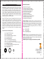
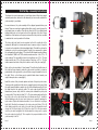
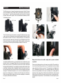
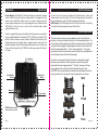
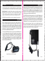
The Fresnel.
Reimagined.
Zylight F8 LED Fresnel
User Instructions
F8-D*, F8-T*, F8-H, F8-U
*
Zylight LLC
World Headquarters:
10718 McCune Avenue
Los Angeles, CA 90034
978-244-0011
[email protected]
F8 Fresnel
Introduction
Introduction: The multiple award-winning F8 LED Fresnel from Zylight
is the next generation of Fresnel lights. By incorporating a special
blend of Quantum nanoparticles with traditional phosphor the F8
boasts a high CRI (color rendering index) and a quality of light matched
only by traditional sunlight and incandescent bulbs, while using a
fraction of the energy. The F8 LED Fresnel is part of Zylight’s pursuit of
high quality, affordable, intelligent fixtures. The unit can be controlled
manually, wirelessly or via DMX controller.
Every F8 LED Fresnel has been thoroughly tested and has been
shipped in optimal operating condition. Carefully check the shipping
carton for damage that may have occurred during shipping. If the
carton appears to be damaged, carefully inspect your fixture for any
damage and be sure all accessories necessary to operate the unit have
arrived intact. If damage has been found or parts are missing, please
contact our customer support number for further instructions. Do not
return this unit to your dealer without first contacting customer
support.
Your F8 includes the following items:
• One - Zylight F8 LED light head
• One – F8 4-way barn door
• One - Yoke bar with 5/8” baby pin adapter
• One - Yoke adjustment knob
• One – Slotted thumbscrew
• Two - 1/4" x .69" OD nylon washers (fig 1)
• Three - 1/2" x .75" OD nylon washers (fig 2)
• One - Serrated #10/M5 x .36" OD, .02" Stainless Washer (fig 3)
• One - Worldwide AC Adapter
• One - AC Adapter hanging pouch (for light stand use)
• One - Barn Door Safety cable
• One – F8 User Guide
fig 1
Page 1
fig 2
fig 3
Optional Accessories:
# 26-02012- F8 Chimera Kit
# 19-02028- F8 Egg Crate (50 deg.)
# 26-02009- F8 Gold Mount Battery Kit
# 26-02010- F8 V-Mount Battery Kit
# 26-02019- DMX Interface Box
# 19-02041- F8 Handle Kit
# 26-02014- F8 Pole Yoke Mount
# 20-06006- F8 Rear AC Adapter Bracket
# 19-02039- F8 Single Head Case
# 19-02040- F8 Dual Head Case
Customer Support: Zylight provides a customer support line, to
provide set up help and to answer any question should you encounter
problems during your set up or initial operation. You may also visit us
on the web at www.zylight.com for any comments or suggestions.
Service Hours are Monday through Friday 9:00 a.m. to 5:00 p.m.
Eastern Standard Time.
Voice: (978) 244-0011
Fax:
(978) 244-0011
E-mail: [email protected]
Caution! There are no user serviceable parts inside this unit. Do not
attempt any repairs yourself; doing so will void your manufacturer's
warranty. In the unlikely event your unit may require service please
contact Zylight customer support.
PLEASE recycle the shipping carton whenever possible.
10718 McCune Avenue
Los Angeles, CA 90034
[email protected]
www.zylight.com
Page 2
F8 Fresnel
General Instructions
To optimize the performance of this product, please read these
operating instructions carefully to familiarize yourself with the basic
operations of this unit. These instructions contain important safety
information regarding the use and maintenance of this unit. Please
keep this manual with the unit, for future reference.
Warranty Registration
The F8 Fresnel carries a two year limited warranty. Please go to
www.zylight.com/product-registration and register your product and
validate your purchase. All returned service items whether under
warranty or not, must be freight pre-paid and accompany a return
merchandise authorization (R.M.A.) number. The R.M.A. number must
be clearly written on the outside of the return package. A brief
description of the problem as well as the R.M.A. number must also be
written down on a piece of paper included in the shipping carton. If the
unit is under warranty, you must provide a copy of your proof of
purchase invoice. You may obtain an R.M.A. number by contacting our
customer support team through our customer support number. All
packages returned to the service department not displaying a R.M.A.
number on the outside of the package will be returned to the shipper.
Safety Precautions
IP Rating:
The F8 is rated IP54 for weather resistance: Ingress of dust is not
entirely prevented, but it will not interfere with satisfactory operation.
Splashing water or light rain or snow will also have no harmful effect.
While the F8 is protected against light moisture and dust exposure,
please protect the instrument when shooting in extreme conditions and
note that the instrument is not rated to be submerged in water, or
exposed to prolonged periods of moisture. Always use your best
judgment and protect the instrument from sustained moisture
exposure.
Page 3
Safety Precautions Cont.
• To reduce the risk of electrical shock or fire, do not
submerge this fixture in water.
• Do not spill large amounts of water or other liquids into or on
to your fixture.
• Do not attempt to operate this unit if the power cord has been
frayed or broken. Do not attempt to remove or break off the
ground prong from the electrical cord. This prong is used to reduce
the risk of electrical shock and fire in case of an internal short.
• Disconnect from main power before making any type of
connection.
• Do not remove the lens under any conditions. There are no user
serviceable parts inside.
• Never operate this fixture if the Fresnel lens is removed.
• Never plug this unit in to a dimmer pack.
• Always be sure to mount this fixture in an area that will allow proper
ventilation. Allow at least 6" (15cm) between this device and a wall.
• Do not attempt to operate this fixture if it becomes damaged.
• During long periods of non-use, disconnect the fixture's main
power.
• Always mount this fixture in safe and stable matter. Always use a
safety cable as part of a secure installation. This includes securing
the barn doors with a safety cable.
• Power-supply cords should be routed so that they are not likely to
be walked on or pinched by items placed upon or against them,
paying particular attention to the point they exit from the fixture.
• Cleaning: The fixture should be cleaned only as recommended by
the manufacturer. See page 10 for cleaning details.
• Heat: The instrument should be situated away from heat sources
such as radiators, heat registers, stoves, or other appliances
(including amplifiers) that produce heat.
• The fixture should be serviced by qualified service personnel when:
A. The power-supply cord or the plug has been damaged.
B. Objects have fallen, or liquid has been spilled into the
instrument.
C. The instrument has been submerged in water
D. The instrument does not appear to operate normally or exhibits
a marked change in performance.
Page 4
First Set Up – Assembly Instructions
To optimize the correct performance of your fixture, please follow these simple
assembly instructions, and refer to this manual if you ever need to reattach the
yoke assembly to your fixture.
In some instances, the yoke assembly will be shipped separated from your
fixture. There are several nylon washers that will be used to correctly space the
metal parts from one another. This will also allow the F8 to be adjusted and
tightened with only one lock point on the left or right side of the yoke. Proper
installation of the washers on the pivot points and the lock points are essential
to maintain the correct operation of the fixture.
The lock point (yoke knob) can be mounted on the left or right side of the
instrument, although it is recommended in most common set ups to keep the
lock point on the right side of the fixture (righty tighty). To install the yoke lay the
instrument on top of a protected surface. Layout your components to mimic
the configuration shown in figure 1. The side with the thumbscrew should have
the Serrated # 10/M5 x .36" OD, stainless washer and two of the 1/2" x .75
nylon washers. The side with the knob lock should have one 1/2" x .75 nylon
washer and the two 1⁄4” x .69 nylon washers. First place a 1/2" x .75 nylon
washer around each side of the pivot located on each of the yoke ears (fig 2).
Fig 1
Fig 2
Fig 3
Fig 4
Fig 5
Fig 6
Fig 7
Fig 8
Next, set the yoke orientation to “lean forward.” You will notice that the base of
the yoke has been shaped so when the yoke mount is vertical in a stand or
perpendicular to the ground, the yoke will sit at an angle towards the front of
the light. This is so the fixture can be pointed further down towards your
subject when placed on a stand (fig 3).
Install the center of the yoke and capture each side of the pivot point screws.
You may need to gently stretch the yoke to engage the pivot point screws. Slide
the small serrated stainless washer onto the slotted thumbscrew (fig 4). Note
the slight bend in the washer’s profile. The outer edge should touch the
thumbscrew (convex side), while the center points towards the pivot point
(concave side). Then take the third 1⁄ 2” x .75 nylon washer and install on the
top of the yoke on the side that will have the thumbscrew. (fig 5). Install the
slotted thumbscrew into the pivot point, being sure to properly capturing the
nylon washer. Tighten the thumbscrew with a coin or other device only finger
tight. (fig 6). Now flip the instrument to the other yoke point. Slide a 1⁄4” x .69
nylon washer under the yoke at the lock point where the threaded hole will
accept the 1⁄4-20 yoke knob. (fig 7). Place the other 1⁄4” x .69 nylon washer
onto the yoke knob and tighten into the threaded hole, being sure to capture
the nylon washer below (fig 8). This completes the proper installation of the
yoke assembly to the F8.
Page 5
Page 6
F8 Fresnel
Barn Door Installation
The F8 includes a set of compact 4-way barn doors as part of the kit. The barn
doors are installed by way of 4 barn door ears. There are two positions for the
barn door ears – open (the packed position) and locked (or the forward
position). Please refer to figures 1 and 2 to understand the different positions
of the barn door ears.
fig 1 – open
fig 2 – locked
To lock the barn doors ears in place to securely hold the barn doors or any
scrims or gels, push the barn door ears forward (towards the front of the light).
Each barn door ear will ‘click’ into a locked position (fig 3). To release each
barn door ear, push center tab of the barn door ear towards the back of the
fixture and the barn door ear will release (fig 4). Make sure that each barn door
ear is securely locked into position before proceeding to the next one.
fig 3
fig 4
To properly install the barn doors, clip and lock the two lower barn door ears
(the two closest to the ground). Clip and lock the top barn door ear that is
furthest from your reach. This will leave one barn door ear still in its flipped
back (packed) position (fig 5). Loop and attach a safety cable to a high secure
point within your fixture, grid, or stand (fig 6). Attach the other end to one of the
top holes found on the four corners of the face of the center portion of the barn
door (fig 7). This tethers the barn door so in case of an accidental release, the
barn doors will hang next to the fixture and not fall away from the fixture.
Failure to properly tether the barn doors can create a dangerous circumstance
for anyone positioned below the fixture.
Page 7
fig 5
fig 6
fig 7
fig 8
fig 9
fig 10
Always tether the barn doors with a safety cable to prevent accidental
separation!
There are two holding positions on the barn door ears (fig 8). The smaller clip,
closest to the Fresnel lens position has a 9” circumference and is for holding
scrims, rigid gels and other accessories. The forward most and slightly wider
9 1⁄2” circumference position clip, is for securing the barn doors. Slide your
barn door, facing forward, into the open ear, being sure to safely guide the
edge ring on the circle portion of the barn doors behind each of the 3 locked
barn door ears (fig 9). Once the barn doors have been secured behind the 3
locked barn door ear positions, lock the 4th barn door ear securely into place
(fig 10).
Page 8
F8 Fresnel
Operations
Power Supply: The Zylight F8 Fresnel contains an automatic voltage
switch, which will auto sense the voltage when it is plugged into the
power source. With this switch there is no need to worry about the
correct power voltage; this unit can be plugged into any outlet rated for
100-240v AC. Also, be sure to only use the included power cable
supplied with the unit.
Power is supplied through a standard 4-pin XLR connector using either
the included Worldwide AC Adapter (P/N 13-17005) or a suitable 14.4V
battery. Please observe correct polarity. Batteries that indicate a full
charge when idle may quickly drop in capacity when under load. For
optimal operation please fully charge batteries before use and be sure
they are rated to provide up to 100W of continuous power, with at least
8.3 amps.
Focus Knob
Yoke/Handle
Mount
Yoke/Handle
Mount
On/Off & Dimming
To turn on the F8 press and release the Dimmer knob. Press and
release again to turn the light off. Turn the Dimmer knob to the right to
increase brightness and to the left to decrease brightness.
LED Display: The LED display will shut off after 5 seconds of inactivity.
To make the display reappear press either button.
Focus Adjustment
The focus knob contains a passive braking system that allows the
bellows to stay in place when the light is in a downward position. For
this system to work properly, there will be a small amount of rotational
movement that engages and disengages the brake at the focus knob
without moving the bellows. This is normal operation. The center
screw that holds the focus knob in place should not be overtightened
or the braking system will not work properly.
Turn the focus knob on the back of the unit to change the output
between spot and flood. At flood position the lens housing will
automatically extend approximately 1” [25mm]. Compress the lens
housing below this level by hand for packing & transport only.
CAUTION: Do not move the lens housing by hand between the flood
& spot positions. Do not force the focus knob past its end stops.
Spot
Dimmer
Power Input
MODE Knob to set
DMX Address & ZyLink Channel
Flood
DMX Breakout Jack
Page 9
Pack
Page 10
F8 Fresnel
Zylink Wireless Control
The F8 has built-in wireless control for adjustment up to 50’ (15m) away
using the Zylight Remote or other Zylight instrument (available separately).
ZyLink Operation: To enable ZyLink control, push & quickly release the
Mode knob, then turn the knob to select the desired wireless channel
(1-10). A wireless symbol will appear in the display when ZyLink is
enabled. To disable ZyLink turn the knob until the display shows OFF.
NOTE: DMX control and ZyLink can not be enabled at the same time.
About DMX
DMX is a language allowing all makes and models of different manufactures
fixtures to be linked together and operate from a single controller, as long as
all fixtures and the controller are DMX compliant. A DMX controller sends DMX
data instructions from the controller to the instrument. DMX is the control data
from the DMX controller sent via 5 pin DMX cable to a single fixture, multiple
lighting fixtures or instruments utilizing the DMX Data IN and DMX Data OUT
jacks located on all DMX enabled instruments.
DMX Control
Operating the F8 LED Fresnel from a DMX controller gives users the option to
create unique lighting looks. The F8 has a single 5-pin DMX Breakout Jack on
the rear of the light to link DMX connections between lights when used in a
DMX chain. The use of a DMX Interface Box (P/N 26-02019) is necessary to
integrate the F8 into DMX chain installations by providing connections for
looping through both DMX IN and DMX OUT data.
The F8 DMX Interface Box plugs directly into the 5-pin DMX Breakout jack
built in to the rear of the F8. If the F8 will be the last light in your DMX chain,
you may plug a 5-pin XLR DMX cable directly into the 5-pin DMX Breakout
Jack. The F8 is a self- terminated device and the use of a DMX terminator or
Zylight DMX interface box will not be necessary when the F8 is the last light in
your DMX chain, or if you are running separate lines to each of your fixtures.
When connecting from fixture to fixture, use of the DMX Interface Box is
necessary for correct DMX connections. Not following these steps for DMX
connection can result in erratic behavior. The DMX Interface Box mounts to
the bottom of either side of the F8 yoke. (see image below)
To ensure proper DMX data transmission, when using several DMX fixtures, try
to use the shortest cable path possible. The order in which fixtures are
connected in a DMX line does not influence the DMX channel addressing. For
example; a fixture assigned to a DMX address of 1 may be placed anywhere
in a DMX line, at the beginning, at the end, or anywhere in the middle. When a
fixture is assigned a DMX address of 1, it will “listen” for any DATA command
sent by the DMX controller to channel 1 and respond accordingly no matter
where it is located in the DMX chain.
Zylight DMX Interface Box (P/N 26-02019)
Page 11
Page 12
DMX cables must be acceptable for DMX data transmission (not
microphone cable) and should follow the standard pin-out. The
maximum DMX data run from any DMX source to the last fixture in a
chain is 1000 feet (300m).
DMX-512 pin-out:
1 Common (Shield)
2 Data –
3 Data +
4 not connected
5 not connected
Cleaning
Due to fog residue, smoke, and dust, cleaning the internal and external
optical lenses must be carried out periodically to optimize light output.
1. Use normal glass cleaner and a soft cloth to wipe down the
outside casing.
2. Clean the external optics with glass cleaner and a soft cloth
as necessary.
3. Always be sure to dry all parts completely before plugging
the unit back in.
NOTE: Connecting pin 4 to pin 5 out of the F8 unterminates the
instrument.
Cleaning frequency depends on the environment in which the fixture
operates (i.e. smoke, fog residue, dust, dew).
To enable DMX mode on the F8, press and hold down the “MODE”
button for 5 seconds. The instrument will enter DMX mode and display
“DMX: ##.” Release the button and turn the “MODE” knob to select a
start address number for the fixture. A start address of 1 to 512 can be
selected for each light. The Dimmer knob will now be disabled while in
DMX mode. All control of the fixture will happen on your DMX console,
including turning the instrument on and off as well as all dimming
control. Plug in a standard 5-pin XLR cable into the DMX Breakout
Jack on the F8 ( if it is the last light in your DMX chain) or into the F8
DMX Interface Box to daisy chain multiple fixtures.
PLEASE NOTE: While in DMX mode all other F8 controls are disabled.
To restore dimming and on/off control to the light, you must take the
unit out of DMX mode. To do this, simply press and hold the “MODE”
button for 5 seconds, and the F8 will go back to manual mode, giving
the user local control of the instrument.
Notice: Do not use the ground lug on the XLR connector. Do not connect the cable's shield conductor to the ground lug or allow the shield
conductor to come in contact with the XLR's outer casing. Grounding
the shield could cause a short circuit and erratic behavior.
DMX Channel Assignments
Page 13
Channel
Function
Values
1
Power
OFF = 0 - 49%
ON = 50 - 100%
2
Brightness
0 - 100%
Page 14
Warranty
2-YEAR LIMITED WARRANTY
A. Zylight LLC warrants to the original end user customer of its products that its
products are free from defects in material and workmanship under normal use for (2)
years from the date of purchase. Except as provided herein, Zylight LLC makes no
express warranties, and any implied warranties, including those of merchantability
and fitness for a particular purpose, are limited in duration to the duration of the
written limited warranties contained herein. Except as provided herein, Zylight LLC
shall have no liability or responsibility to its customer or any other person or entity
with respect to any liability, loss or damage caused directly or indirectly by use or
performance of the product or arising out of any breach of this warranty, including,
but not limited to, any damages resulting from inconvenience, loss of time, data,
property, revenue or profit or any indirect, special, incidental or consequential
damages, even if Zylight LLC has been advised of the possibility of such damages.
B. In the event of a product defect during the warranty period, you must contact Zylight
LLC at the phone number or address listed in the product’s user manual or on the
internet at www.zylight.com to obtain a return merchandise authorization (R.M.A.)
number. After obtaining an RMA number, send the product fully insured, with proof
of purchase, to the address given to you by the Customer Service representative.
Zylight LLC will, at its option, repair or replace the defective product.
C. All replaced parts and products become the property of Zylight LLC. Repaired or
replacement parts and products are warranted for the remaining term of the original
warranty period. You will be charged for materials and labor or replacement of the
product after the expiration of the warranty period.
D. This warranty does not cover: (a) damage or failure caused by or attributable to acts
of God, abuse, accident, drops, misuse, improper or abnormal usage, failure to
follow instruction, improper installation or maintenance, alteration, lightning or other
incidence of excess or reverse voltage or current, exposure to excess dampness or
moisture; (b) removal of, or tampering with any attached stickers, decals, knobs,
enclosures, protective windows, hardware, or fasteners; (c) use of power supply
equipment, power adapters, or cables not supplied by Zylight LLC for specific use
with the equipment for which it was specified; (d) any unauthorized disassembly,
repair, or modification; (e) cosmetic damage; (f) transportation, shipping, or
insurance costs; (g) costs of product removal, installation, set-up, service
adjustment, or reinstallation; (h) cracking, abrasion, scratching, coating wear, or
breakage of protective windows or lenses; (i) abnormal mechanical or environmental
conditions; (j) product that has been has been sold as second-hand; (k) product that
has been transported, shipped, purchased, or resold contrary to US export
regulations; (l) product that has been transported, shipped, purchased, or resold
outside countries for which it has received electronic product compliance
certification.
Page 15
Warranty
E. This is not a service contract, and this warranty does not include maintenance,
cleaning, or periodic check-up. During the period specified above, Zylight will
replace defective parts at its expense, and will absorb all expenses for warranty
service and repair labor by reason of defects in material or workmanship. The sole
responsibility of Zylight under this warranty shall be limited to the repair of the
product, or replacement thereof, including parts, at the sole discretion of Zylight. All
products covered by this warranty were manufactured after April 1, 2014, and bear
identifying marks to that effect.
F. Zylight reserves the right to make changes in design and/or improvements upon its
products without any obligation to include these changes in any products theretofore
manufactured.
G. No warranty, whether expressed or implied, is given or made with respect to any
accessory supplied with products described above. Except to the extent prohibited
by applicable law, all implied warranties made by Zylight in connection with this
product, including warranties of merchantability or fitness, are limited in duration to
the warranty period set forth above. And no warranties, whether expressed or
implied, including warranties of merchantability or fitness, shall apply to this product
after said period has expired. The consumer's and or Dealer's sole remedy shall be
such repair or replacement as is expressly provided above.
H. This warranty is the only written warranty applicable to Zylight Products and
supersedes all prior warranties and written descriptions of warranty terms and
conditions heretofore published. Under no circumstances shall Zylight be liable for
any loss or damage, direct or consequential, arising out of the use of, or inability to
use, this product.
I. This warranty gives you specific legal rights, and you may also have other rights
which vary from state to state.
Register your instrument at - www.zylight.com/product-registration
Page 16
F8 Fresnel
Parts Diagram
Replacement Parts Key
1. Fresnel Lens (14-01009)
2. Barn Door Ear Kit (x1) (26-03028)
3. Fresnel Retainer Clip Kit (x4) (26-03026)
4. Antenna (13-14001)
5-9. Yoke Washers, Knob and Thumbscrew Kit (26-03022)
10-13. Focus Knob and Brake Assembly (26-03023)
14. On/Off or MODE Knob (x1) (12-03006)
15. Yoke Bar (19-01005)
16-21. Yoke Mount Kit (26-02015)
2
1
3
4
Specifications
Optical Dimension
Size
Weight
Power Requirement
Power Consumption
Power Input Plug
AC Power Supply
Color Temperature
10
11
7
5
6
7
8
9
12
13
CRI Index
Beam Angle
Method of Focus
Intensity
Dimming
Cooling
Operating Range
Electrical Option
Mounting
15
14
16
17
20
Page 17
18
19
21
Wireless Frequency
Wireless Channels
Assembly Materials
Calibration
IP Rating
DMX
PWM
LED Life
Flicker Free
8” Round Schott glass Fresnel lens [203mm]
15” x 12.6” x 4.6” [382mm x 319mm x 97mm]
10.9 lbs [4.3Kg] w/ Yoke
10-20 VDC
100W max. [8.0A @ 14VDC]
XLR 4-Pin
120 – 240V AC, 50/60Hz
Fixed. F8-T (#26-01019) 3200K,
F8-D (#26-01025) 5600K
F8-T (3200K) 94+ CRI, F8 D (5600K) 92+ CRI
16°- 70°, Variable Spot-Flood
Rear knob. Continuously variable.
No modifying lenses needed
0-100%
Passive/Silent
-20 – +40 C
Worldwide AC power supply (included)
14.4VDC (8 AMP) camera battery powering:
V-Mount (26-02010)
Gold-Mount (26-02009)
Manual yoke, 5/8” Female spigot (included)
Pole yoke (26-02014)
Handle Kit (19-02041)
2.45 GHz
10, User Selectable
Machined aluminum and high impact plastic
Factory
54
2 Channels
11.8 KHz
50,000 hrs.
Up to 5,600 fps tested (full brightness)
Page 18