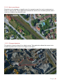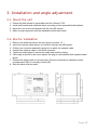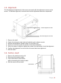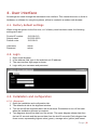
1
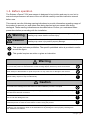
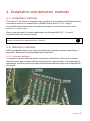
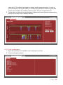
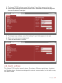
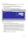
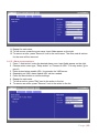
User Manual vFence ® F-501 Laser surveillance sensor for network integration C Contents 1. Introduction .......................................................................................................................... 2 1.1. Features ........................................................................................................................ 2 1.2. Trademark ..................................................................................................................... 2 1.3. Before operation ............................................................................................................ 3 1.4. Precautions ................................................................................................................... 4 1.5. Part identification ........................................................................................................... 4 2. Installation and detection methods ....................................................................................... 5 2.1. Installation methods....................................................................................................... 5 2.2. Detection methods......................................................................................................... 5 2.2.1. Perimeter detection ................................................................................................. 5 2.2.2. Spot surveillance..................................................................................................... 6 2.2.3. Change detection .................................................................................................... 6 3. Installation and angle adjustment ......................................................................................... 7 3.1. Mount the unit ................................................................................................................ 7 3.2. Electric installation ......................................................................................................... 7 3.3. Alignment ...................................................................................................................... 8 3.4. Factory reset ................................................................................................................. 8 4. User interface ....................................................................................................................... 9 4.1. Factory default settings ................................................................................................. 9 4.2. Login.............................................................................................................................. 9 4.3. Installation and configuration ......................................................................................... 9 4.3.1. Alignment ................................................................................................................ 9 4.3.2. Unit configuration .................................................................................................. 10 4.4. Alarm settings .............................................................................................................. 11 4.4.1. Zone alarms .......................................................................................................... 12 4.4.2. Alarm zones actions .............................................................................................. 13 4.4.3. Reference point..................................................................................................... 14 4.4.4. Heartbeat .............................................................................................................. 15 4.4.5. Weather alarm ...................................................................................................... 16 4.5. Logout ............................................................................................................................. 17 Page |1 1. Introduction The Embsec vFence F-501 is a powerful sensor for detecting objects and humans with high accuracy at long distances, without the needs of lights, reflectors or separate transmitters/receivers used by other systems. Calculating the distance to any object up to 500 metres away at 400 Hz, the sensor has the ability of lowering the false alarm rate to a minimum while increasing the number of detected objects. 1.1. Features Field of application Alarm zones Alarm actions Self awareness Outdoor surveillance and monitoring Up to 20 fully adaptable zones, each zone has individual alarm sensitivity settings and alarm actions Network alarm, relay. Easy direct integration with IP to VMS, enabling PTZ control, automatic video recording and object position Adaptive digital processing algorithm suppresses noise from fog and snow, and detects challenging weather to allow alarms to VMS Detection range Detection resolution Update rate 0 - 500 meters +/- 1 dm 400 Hz Laser wavelength Beam divergence Alignment laser Laser class 905 nm 2.0 x 0.2 mRad Yes Class 2 laser product, eye-safe Power supply Power consumption Operating temperature Interface Relay switch Power over Ethernet (48V DC) 4W, PoE class 2 - 30°C to + 60°C Ethernet IEEE 802.3af, TCP/IP, web browser user interface Max 30V 200mA, NC and NO Mounting 4 x M6 - Bosch compatible (72 x 40 mm ) 4 x M6 - Axis compatible (40 x 62 mm) 5/8"-11 UNC (Tripod mount) IP66 Shell: grey, sensor: black 2.3 kg Enclosure rating Color Weight 1.2. Trademark vFence® is a registered trademark licensed to Embsec AB, registration number 0501082 by The Swedish Patent and Registration Office. The name must always be written with a lowercase v directly followed by the word Fence with an upper-case F. Page |2 1.3. Before operation The Embsec vFence F-501 laser sensor is designed to be intuitive and easy to use, but to ensure best performance all users of the unit should carefully read this instruction manual before use. This manual uses the following warning indications to provide information regarding usage of the product to prevent you and others from being harmed and your assets from being damaged. These warning indications are described below. Ensure you understand these precautions before proceeding with the installation. Warning Failure to follow the instructions provided by this warning and improper handling may cause death or serious injury. Caution Failure to follow the instructions provided by this caution and improper handling may cause injury and/or property damage. This symbol indicates prohibition. The specific prohibited action is provided in and/or around the figure. ! This symbol requires an action or gives an instruction. Warning Do not use the product for purposes other than detection of people and vehicles. Do not use the product to activate doors or other moving objects, which may cause an accident. Never attempt to disassemble or repair the product. It may cause fire or damage to the devices. Hold the main unit securely when you install or service it. Exercise care not to bump the product against nearby objects or drop it inadvertently. ! Caution Do not stare directly into the red alignment laser. Do not leave the red alignment laser turned on after installation process is complete. Only use approved Power over Ethernet power supplies. Never try to power the device in other ways than with the RJ45 PoE connection. Do not touch the unit connections with a wet hand or when the product is wet with rain. It may cause short circuit and damage the unit. Clean and check the product periodically for safe use. If any problem is found, contact Embsec or authorized partner to solve the issue before continue using the product. ! ! ! This product is intended to detect intruders and is not designed to prevent theft, disasters or accidents. The manufacturer shall not be held liable for any damage to user's property resulting from theft, disasters or accidents. Page |3 1.4. Precautions Only use wall brackets and tripod with compatible mounting. Install the product only on a solid surface. Install the product so that the detection line is not influenced by interference from tall grass or tree branches waiving in the wind. For perimeter protection, the unit should be placed at desired detection height and parallel to ground. Do not install or leave the product in a location exposed to heat, vibrations or impacts. 1.5. Part identification Page |4 2. Installation and detection methods 2.1. Installation methods The vFence F-501 sensor is compatible with a number of conventional wall brackets used for surveillance cameras, for example Bosch EXMB.028 and Axis 0217-031. Using a conventional wall bracket means all standard accessories, such as pole mounts, corner mounts etc., can be used. When using the product for mobile applications, the threaded UNC 5/8" - 11 hole is compatible with most surveyor tripods. The sensor must always be mounted on a steady foundation, such as a wall or a pole that is well secured to minimize risk of misalignment due to vibrations. ! 2.2. Detection methods With fully adaptable alarm zones, the product has many detection methods depending on application. Below are three typical applications described. 2.2.1. Perimeter detection The product is used to detect all objects crossing the virtual fence. Zones can be created along the line of sight to permit different actions based on object location. For these types of applications, the sensor should be placed at the desired detection height and be aligned with the ground. Page |5 2.2.2. Spot surveillance Detection is only desired in a specific area, for example a part of a road, an entrance to a house or along a wall. These applications allows the sensor to be located anywhere with a clear line of sight to the detection area. 2.2.3. Change detection The product is used to detect if an object moves. This application allows the sensor to be located anywhere with a clear line of sight to the object. Page |6 3. Installation and angle adjustment 3.1. Mount the unit 1. 2. 3. 4. Ensure the wall bracket is compatible with the vFence F-501. Install wall bracket and additional items according to their associated descriptions. Mount the unit on the wall bracket with the four M6 screws. Make a rough alignment with the adjustable wall bracket head. 3.2. Electric installation 1. 2. 3. 4. 5. 6. Remove the shell and service lid (see figure in section 1.5.) Insert the network cable without a connector through the cable gland. Follow your connector assembly instruction to patch the network cable. Connect the network cable in the RJ45 connector. Tighten the cable gland to secure the cable and seal the casing. If the relay is desired to be used, replace the plug on the backside with supplied cable gland. 7. Connect the signal cable to the terminals. Choose connection for desired function, normally open (NO) or normally closed (NC). 8. Refit the service lid and shell. Page |7 3.3. Alignment The final alignment adjustment of the sensor are made with the adjustment screws on the sensor. To facilitate alignment, horizontal and vertical adjustment have been separated. Vertical alignment screws Horizontal alignment screws 1. 2. 3. 4. 5. 6. 7. Remove the shell. Fasten the telescopic sight (optional) with the quick release mounts. Release all adjustment screws using a 2.5mm Allen key. Screw on one side to push the sensor in the desired direction. When the sensor is aligned, tighten the screws from both sides to lock the alignment. Confirm that alignment is correct after all screws have been tightened. Refit the shell. 3.4. Factory reset 1. Remove the shell and service lid. 2. Disconnect the network cable. 3. Press and hold the reset button, while reconnecting the network cable. 4. Refit the service lid and shell. Reset button Page |8 4. User interface All settings are made through the web based user interface. This means there are no limits in hardware or software for using the systems, all that is needed is a modern web browser. 4.1. Factory default settings When using the system for the first time, or if a factory reset has been made, the following settings are used. Product IP number Subnet mask Default router 192.168.0.10 255.255.255.0 192.168.0.1 Username Password admin admin 4.2. Login 1. 2. 3. 4. Open a web browser In the address field, type in the selected unit IP-address. The user interface login page is shown. Login with your username and password. 4.3. Installation and configuration 4.3.1. Alignment 1. Open the installation and configuration tab 2. The default sub-tab is the alignment window. 3. Turn on and off the alignment laser with the buttons. Remember to turn off the laser when the installation process is complete. 4. Two diagrams shows live data from the sensor. The upper diagram shows data from the last 10 seconds and the second data from the last 60 seconds. Each diagram has three curves, representing highest value (green), average value (yellow) and lowest Page |9 value (blue). This allows the diagram to display rapid changes accurate. It is also a good indication of the signal stability. A remaining big difference between highest and lowest value indicates an unstable reference point, such as tree branches etc. 5. To the right is a table with current distance, highest and lowest distance measured the last 60 second and current weather intensity. 4.3.2. Unit configuration 1. Open the sub-tab in the installation and configuration window. 2. Current settings are shown. P a g e | 10 3. To change TCP/IP settings, press "edit settings". Input fields appear to the right. 4. Enter desired settings and press the save button. Remember to reload the page with the new IP address if changed. 5. To change Login settings, press "edit settings". Input fields appear to the right. 6. Enter a new username and password. 7. Press the save button to confirm. 4.4. Alarm settings The vFence F-501 has four types of alarms, Zone alarm, Reference point alarm, Heartbeat and Weather alarm. All alarms are designed for network communication, but the built-in relay can also be used. P a g e | 11 4.4.1. Zone alarms Zone alarms are standard alarm for object detection. Up to 20 zones can be created and each zone can have individual settings and alarm actions. 1. 2. 3. 4. 5. In the Alarm settings tab, open the Zone alarms sub tab (default) Press "+ Add zone" to create an alarm zone. Input fields appear on the right. Enter a unique zone name. Enter the near distance, the distance at which the zone should start. Enter the far distance, the distance at which the zone should end. Steps 6 to 9 regards advanced settings. These settings are not necessary but can be used to adapt the zones for special purposes. We recommend to thoroughly verify the function of the alarm zone if these settings are changed. 6. Press "Advanced settings". Three new settings are shown. 7. The sensitivity bar allows adjustment of the object detection sensitivity. Increased sensitivity can be used for applications where highest detection is necessary, but will also slightly increase the risk of false alarms. Decreased sensitivity are used for applications where the objects are big and slow, for example detection of boats. 8. Alarm delay is a timer to allow a zone alarm to react if an object has stopped in the zone. Enter the time for which an object must stay in the zone before the alarm is activated. Default value is 0 seconds, maximum is 2 minutes. 9. Timeout specifies the time before a zone alarm resets after an object has been detected. This can be used to avoid extra alarms from objects that creates multiple detections, for example masts on a boat. Default value is 0 seconds, maximum is 2 minutes. 10. Press Add zone button to save the zone settings. P a g e | 12 11. Repeat for each zone. 12. To edit a zone, press the zone name. Input fields appear on the right. 13. To remove a zone, press "Remove" next to the zone name. The zone and all actions for the zone will be removed. 4.4.2. Alarm zones actions 1. Press "+ Add action" under the desired alarm zone. Input fields appear on the right. 2. Choose action event type, "Relay action" or "Connect to URL". For relay action, go to point 5. 3. Enter desired alarm enable URL, for example the VMS server. 4. Depending on VMS, alarm disable URL can be needed. 5. Press the save button to confirm settings. 6. Repeat for each zone. 7. To edit an action, press "Edit" next to the action in the list. 8. To remove an action, press "Remove" next to the action in the list. P a g e | 13 4.4.3. Reference point Reference point alarm is a tampering alarm used to detect if the sensor has moved or covered. Reference point alarm is only possible when the product is aligned in a manner where there is a reference object and the signal stability is good. 1. In the Alarm settings tab, open the Reference point sub tab 2. Press "+ Add reference point". Input fields appear on the right. 3. Enter distance to reference point. 4. Enter target variance, the maximum allowed change in distance relative to the reference point before the alarm is trigged. 5. Enter alarm delay, the time which the reference point must be faulty before alarm is sent. To avoid false alarms, the alarm delay should be significantly different from the time of a standard object passage. 6. Press the Add button to confirm the settings. P a g e | 14 7. Create Alarm actions for the reference point by pressing "+ Add action". Input fields appear on the right. 8. Choose action event type, "Relay action" or "Connect to URL". For relay action, go to point 11. 9. Enter desired alarm enable URL, for example the VMS server. 10. Depending on VMS, alarm disable URL can be needed. 11. Press the save button to confirm settings. 4.4.4. Heartbeat Heartbeat is a tampering alarm used to detect cable break and product malfunction by periodically send a short message to the server. 1. In the Alarm settings tab, open the Heartbeat sub tab P a g e | 15 2. 3. 4. 5. Press "Edit settings". Input fields appear on the right. Enter desired URL for heartbeat, for example the VMS server. Enter desired time interval between heartbeats. Press the save button to confirm the settings. 4.4.5. Weather alarm The unit constantly evaluates the measurement signal to determine the weather intensity at a scale from 0 to 10 to allow alarm actions based on weather intensity. 1. 2. 3. 4. In the Alarm settings tab, open the Weather alarm sub tab Press "+ Add weather alarm". Input fields appear on the right. Enter desired threshold level on weather intensity alarm (default is 1) Enter timeout, the shortest time the weather alarm is active. Each time the weather intensity exceeds the threshold, the timeout is reset. Default time is 10 minutes. 5. Press the Add button to confirm the settings. P a g e | 16 6. Create Alarm actions for the weather alarm by pressing "+ Add action". Input fields appear on the right. 7. Choose action event type. Connect to URL If the weather intensity threshold is exceeded, the unit alarms to the URL. - Enter desired URL, for example the VMS server. - Depending on VMS, alarm disable URL can be needed. Relay action Activates the internal relay Disable reference point If the weather intensity threshold is exceeded, reference point alarms are ignored. 8. Press the Add action button to confirm settings. 4.5. Logout 1. Press the "Logout" tab in the top menu. 2. You will automatically be logged out if anybody log in from another computer. P a g e | 17 C www.embsec.com Embsec AB Propellervägen 10 SE-183 62 Täby Sweden Tel: +46 (0) 8 - 522 45 290 Fax: +46 (0) 8 - 446 48 39 Mail: [email protected] P a g e | 18