1
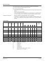
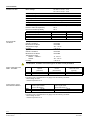
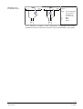
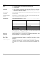
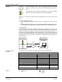
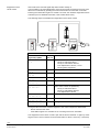
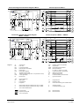
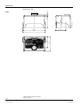
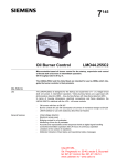
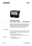
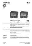
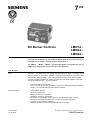
7
130
ISO 9001
Oil Burner Controls
LMO14...
LMO24...
LMO44...
Microcontroller-based oil burner controls for the startup, supervision and control
of forced draft oil burners in intermittent operation. Standard versions with an oil
throughput up to 30 kg / h, special versions above 30 kg / h.
The LMO14..., LMO24..., LMO44... and this Data Sheet are intended for use by
OEMs which integrate the burner controls in their products.
Use, features
Use
General features
CC1N7130en
15.10.2002
The LMO... are designed for the startup and supervision of single- or 2-stage forced
draft oil burners in intermittent operation. Yellow-burning flames are supervised with
photoresistive detectors QRB..., blue-burning flames with blue-flame detectors QRC...
In terms of housing dimensions, electrical connections and flame detectors, the LMO...
are identical with the LOA... oil burner controls.
-
Oil burners with fans to EN 267
Burner controls for use with atomization oil burners of monoblock design to EN 230
LMO44... for use with stationary direct-fired air heaters
-
Undervoltage detection
Electrical remote reset
Bridging contact for oil preheater
Monitoring of time for oil preheater
Accurate and reproducible control sequence through digital signal handling
Controlled intermittent operation after 24 hours of continuous operation
Limitation of the number of repetitions
Multicolor indication of fault and operational status messages
Siemens Building Technologies
HVAC Products
Warning notes
To avoid injury to persons, damage to property or the environment, the following
warning notes should be observed!
Do not open, interfere with or modify the unit!
·
·
·
·
·
ARK21...
·
Before performing any wiring changes in the connection area of the LMO..., completely isolate the burner control from the mains supply (all-polar disconnection)
Ensure protection against electric shock hazard by providing adequate protection
for the burner control’s connection terminals
Check to ensure that wiring is in an orderly state and that the wires are firmly connected
Press the lockout reset button / operation button only manually (applying a force of
no more than 10 N), without using any tools or pointed objects
Fall or shock can adversely affect the safety functions. Such units may not be put
into operation, even if they do not exhibit any damage
When replacing LOA26... or LOA36..., any remote lockout reset module ARK21...
or similar modules contained in the burner or boiler must be removed
Mounting notes
·
Ensure that the relevant national safety regulations are complied with
·
·
Installation work must be carried out by qualified staff
Always run the high-voltage ignition cables separately while observing the greatest
possible distances to the unit and to other cables
Install switches, fuses, earthing, etc., in compliance with local regulations
Ensure that the maximum permissible amperages will not be exceeded (refer to
«Technical data»)
Do not feed external mains voltage to the control outputs of the unit. When testing
the components controlled by the burner control (fuel valves, etc.), the LMO... may
never be plugged in
Do not mix up live and neutral conductors
Installation notes
·
·
·
·
Electrical connections of the flame detectors
It is important to achieve practically disturbance- and loss-free signal transmission:
· Never run the detector cable together with other cables
– Line capacitance reduces the magnitude of the flame signal
– Use a separate cable
· Observe the maximum permissible lengths of the detector cables (refer to «Technical data»)
2/12
Siemens Building Technologies
HVAC Products
CC1N7130en
15.10.2002
Commissioning notes
·
·
Commissioning work must be carried out by qualified staff
When commissioning the plant or when doing maintenance work, make the following safety checks:
Safety check
a)
b)
c)
Burner startup with flame detector darkened
Burner startup with flame detector exposed to extraneous light
Burner operation with simulated loss of
flame; for that purpose, darken the flame
detector during operation and maintain
that state
Anticipated response
Lockout at the end of «TSA»
Lockout after 40 seconds at the
latest
Repetition followed by lockout at
the end of «TSA»
Norms and standards
Conformity to EEC directives
- Electromagnetic compatibility EMC (immunity)
- Low-voltage directive
89 / 336 EEC
73 / 23 EEC
Service notes
·
·
·
Maintenance work must be carried out by qualified staff
Each time a unit has been replaced, check to ensure that wiring is in an orderly
state and that the wires are firmly connected. Make the safety checks as detailed in
«Commissioning notes»
Use the service adapters KF8885 / KF8833 / KF8840 for only short periods of time
Disposal notes
The unit contains electrical and electronic components and may not be disposed of
together with household waste.
Local and currently valid legislation must be observed.
3/12
Siemens Building Technologies
HVAC Products
CC1N7130en
15.10.2002
Mechanical design
The housing is made of impact-proof, heat-resistant and flame-retarding plastic.
It is of plug-in design and engages audibly in the base.
The housing accommodates the
microcontroller, which controls the control sequence, and the control relays for load
control
electronic flame signal amplifier
lockout reset button with its integrated 3-color signal lamp for operational status
and error messages and the socket for connecting the interface adapter OCI400
-
Indication and diagnosis
-
Multicolor indication of operational status and error messages
Transmission of operational status and error messages and detailed service information through additional interface adapter OCI400 and PC Windows software
ACS400
Type summary
Type reference
Mains
Fuel
Burner
voltage
valve
capacity
¹)
Remote
Times
Comparable
reset
type of
stages
LOA...
tw
t1 / t1´
TSA-
t3
t3n
t4
max.
min.
max.
min.
max.
min.
Standard versions
LMO14.111B2
AC 230 V
1
< 30 kg / h
·
·
5s
15 / 16 s
10 s
15 s
10 s
---
LOA24.171B27
LOA26.171B27
LOA36.171A27
LOA24.171B17
LMO14.111B1
AC 110 V
1
< 30 kg / h
·
·
5s
15 / 16 s
10 s
15 s
10 s
---
LMO14.113B2
AC 230 V
1
< 30 kg / h
·
·
5s
15 / 16 s
10 s
15 s
3s
---
LOA24.173A27
LMO24.111B2
AC 230 V
2
< 30 kg / h
·
·
5s
15 / 16 s
10 s
15 s
10 s
15 s
LOA24.171B27
LOA26.171B27
LOA36.171A27
LMO24.111B1
AC 110 V
2
< 30 kg / h
·
·
5s
15 / 16 s
10 s
15 s
10 s
15 s
LOA24.171B17
LMO24.113B2
AC 230 V
2
< 30 kg / h
·
·
5s
15 / 16 s
10 s
15 s
3s
15 s
LOA24.173A27
LMO24.255B2
AC 230 V
2
</> 30 kg/h
·
·
5s
25 / 26 s
5s
25 s
5s
15 s
---
2
< 30 kg / h
·
·
5s
5/6s
10 s
5s
10 s
15 s
LOA24.571C27
2
</> 30kg / h
·
·
5s
25 / 26 s
5s
25 s
5s
5s
LOA44.252A27
Version for flash-steam generators
LMO24.011B2
AC 230 V
Suited for direct-fired air heaters
LMO44.255B2
AC 230 V
Legend
TSAmax.
Maximum ignition safety time
tw
Waiting time
t1
Prepurge time
t1’
Purge time
t3
Preignition time
t3n
Postignition time
t4
Interval from flame signal to release of «BV2»
¹)
Bridging contact for oil preheater
4/12
Siemens Building Technologies
HVAC Products
CC1N7130en
15.10.2002
Ordering
Oil burner control (without plug-in base)
refer to «Type summary»
Electrical connections
- Plug-in base AGK11...
- Cable holders AGK65..., AGK66, AGK67...
- Cable strain relief elements for AGK67...
refer to Data Sheet 7201
Electrical connections
- Plug-in base AGK13...
- Plug-in housung AGK56...
- Cover AGK68...
refer to Data Sheet 7203
Flame detectors
- Photoresistive detectors QRB1...
- Blue-flame detector QRC1...
Diagnostic tool
- Interface adapter OCI400
- PC Windows software ACS400
refer to Data Sheet 7714
refer to Data Sheet 7716
refer to Data Sheet 7614
Demo case
For demonstrating the functions of burner controls
(refer to User Manual B7989)
KF8891
Test case
For checking the functions of burner controls
(refer to Operating Instructions C7981)
KF8843
Test adapter
For checking the functions of burner controls on the burner
With switch for manual startup of the burner
With switch for simulating the oil preheater’s release contact
With 2 pairs of jacks for measuring the flame detector current
(refer to Operating Instructions C7986)
KF8885
Test adapter
For checking the functions of burner controls on the burner
With signal lamps for program indication
With one pair of jacks for measuring the flame detector current
KF8833
-
-
-
Test adapter
KF8840
For checking the functions of burner controls on the burner
With signal lamps for program indication
With on / off switch for simulating the flame signal
With holes for checking the control voltages at the tabs of the burner control
With one pair of jacks for measuring the flame detector’s resistance
-
5/12
Siemens Building Technologies
HVAC Products
CC1N7130en
15.10.2002
Technical data
General unit data
Mains voltage
Mains frequency
External primary fuse (Si)
Power consumption
Mounting orientation
Weight
Safety class
Degree of protection
Perm. cable lengths
Detector cable laid separately
Remote reset laid sepatately
Max. perm. amperage at cos j ³ 0.6
Terminal 1
Terminals 3 and 8
Terminals 4, 5, 6 and 10
Environmental
conditions
Transport
Climatic conditions
Mechanical conditions
Temperature range
Humidity
Operation
Climatic conditions
Mechanical conditions
Temperature range
LMO14... / LMO24...
LMO44...
Humidity
AC 230 V +10 % / -15 %
AC 110 V +10 % / -15 %
50...60 Hz ±6 %
6.3 A (slow)
12 VA
optional
approx. 200 g
I
IP 40 (to be ensured through mounting)
max. 3 m at a line capacitance of 100 pF/m
20 m
20 m
LMO14...
5A
3A
1A
LMO24... / LMO44...
5A
5A
1A
DIN EN 60 721-3-2
class 2K2
class 2M2
-30...+70 °C
< 95 % r.h.
DIN EN 60 721-3-3
class 3K5
class 3M2
-5...+60 °C
-20...+60 °C
< 95 % r.h.
Condensation, formation of ice and ingress of water are not permitted!
Flame supervision with
QRB... and QRC...
QRB...
QRC...
Min. detector current
required
(with flame)
45 µA
70 µA
Max. perm. detector
current
(without flame)
5.5 µA
5.5 µA
Max. possible detector
current with flame
(typically)
100 µA
100 µA
The values given in the table above only apply under the following conditions:
- Mains voltage AC 230 V
- Ambient temperature 23 °C
Green LED for operational status indication
QRB...
QRC...
Detector current in operation:
- Flame signal instable
- Green LED flashing
< 45 µA
< 45 µA
Detector current in operation:
- Flame signal stable
- Green LED steady on
> 45 µA
> 45 µA
The values given in the table above only apply under the following conditions:
- Mains voltage AC 230 V
- Ambient temperature 23 °C
6/12
Siemens Building Technologies
HVAC Products
CC1N7130en
15.10.2002
Measuring circuit
for detector current
11
QRB...
12
sw
bl
+
LMO...
7130v01/0700
11
bl
QRC...
12
sw
+
1
br
LMO...
7130v02/0700
Legend
µA DC
µA DC
µA DC
bl
sw
br
QRB...
DC microammeter
with an internal
resistance of
Ri = max. 5 kW
Blue
Black
Brown
QRC1...
As an alternative to detector current measurement, the diagnostic tool OCI400 /
ACS400 can be used. In that case, connection of a DC microammeter is not required.
7/12
Siemens Building Technologies
HVAC Products
CC1N7130en
15.10.2002
Function
Preconditions for
startup
·
·
·
·
Burner control is reset
All contacts in the line are closed and there is demand for heat
No undervoltage
Flame detector is darkened and there is no extraneous light
Undervoltage
·
Safety shutdown in the operating position takes place should mains voltage drop
below about AC 165 V (UN = AC 230 V)
Restart is initiated when mains voltage exceeds about AC 175 V (UN = AC 230 V)
·
Time supervision
oil preheater
If the oil preheater’s release contact does not close within 10 minutes, the burner control
will initiate lockout.
Controlled intermittent
operation
After 24 hours of continuous operation at the latest, the burner control will initiate automatic controlled shutdown followed by a restart.
Control sequence in
the event of fault
If lockout occurs, the outputs for the fuel valves, burner motor and ignition equipment
will immediately be deactivated (< 1 second).
Cause
Mains failure
Voltage has fallen below the undervoltage
threshold
Extraneous light during «t1»
Extraneous light during «tw»
No flame at the end of «TSA»
Loss of flame during operation
Oil preheater’s release contact does not
close within 10 minutes
Response
Restart
Restart
Lockout at the end of «t1»
Prevention of startup, lockout after 40 seconds at the latest
Lockout at the end of «TSA»
Max. 3 repetitions, followed by lockout
Lockout
In the event of lockout, the LMO... remains locked and the red signal lampLED will light
up. The burner control can immediately be reset.
This state is also maintained in the case of mains failure.
Resetting the
burner control
Whenever lockout occurs, the burner control can immediately be reset. To do this, press
the lockout reset button for about 1 second (< 3 seconds).
Ignition program with
LMO14.113B2 and
LMO24.113B2
If the flame is lost during «TSA», the burner will be reignited, but only until the end of
«TSAmax».
This means that several ignition attempts can be made during «TSA» (refer to «Control
sequence»).
Limitation of repetitions
If the flame is lost during operation, a maximum of 3 repetitions can be made.
If the flame is lost for the fourth time during operation, the burner will initiate lockout.
The repetition count is restarted each time controlled switching on by «R-W-SB» takes
place.
8/12
Siemens Building Technologies
HVAC Products
CC1N7130en
15.10.2002
Operation
7130z05/0700
Operation, display, diagnosis
EK
7130z06e/0700
Red
Yellow
Green
Lockout reset button «EK...» is the key operating element for resetting
the burner control and for activating / deactivating the diagnostic functions.
The multicolor LED in the lockout reset button is the key indicating
element for both visual diagnostics and interface diagnostics.
LED
Both «EK...» and LED are located under the transparent cover of the lockout reset
button.
There are 2 diagnostic choices:
1. Visual diagnostics: Operational status indication or diagnostics of the cause of
fault.
2. Interface diagnostics: With the help of the interface adapter OCI400 and PC software ACS400 or flue gas analyzers of different makes (refer to Data Sheet 7614).
Visual diagnostics:
In normal operation, the different operational statuses are indicated in the form of color
codes according to the color code table. The interface diagnostics is activated by
pressing the lockout reset button for at least 3 seconds (refer to Data Sheet 7614). If,
by accident, the interface diagnostics has been activated, in which case the slightly red
light of the signal lamp LED flickers, it can be deactivated by pressing again the lockout
reset button for at least 3 seconds. The moment of switching over is indicated by a
yellow light pulse.
Operating position
Operating position
Visual diagnostics
Interface diagnostics
PC / analyzer
Color code table
xxxxxxxx
xxxxxxxx
xxxxxxxx
xxxxxxxx
xxxxxxxx
xxxxxxxx
Operational status
indication
7130z01e/0602
>3s
EK
During startup, status indication takes place according to the following table:
Color code table for multicolor signal lamp LED
Status
Color code
Color
❍......................................
Waiting time «tw», other waiting states
Off
●.......................................
Oil preheater on, waiting time «tw»
Yellow
Ignition phase, ignition controlled
Flashing yellow
● ❍● ❍● ❍● ❍● ❍
❏.......................................
Operation, flame o.k.
Green
Operation, flame not o.k.
Flashing green
❏ ❍❏ ❍❏ ❍❏ ❍❏ ❍
Extraneous light on burner startup
Green-red
❏s❏s❏s❏s❏
Undervoltage
Yellow-red
●s●s●s●s●s
s.......................................
Fault, alarm
Red
Flashing red
Error code output (refer to «Error code
s❍ s❍ s❍ s❍
table»)
Interface diagnostics
Red flicker light
s s s s s s s s
Legend
...... Steady on
Off
❍
s
●
❏
Red
Yellow
Green
9/12
Siemens Building Technologies
HVAC Products
CC1N7130en
15.10.2002
Diagnostics of the
cause of fault
After lockout, the red fault signal lamp LED remains steady on.
In that condition, the visual diagnostics of the cause of fault according to the error code
table can be activated by pressing the lockout reset button for more than 3 seconds.
Pressing the reset button again for at least 3 seconds, the interface diagnostics will be
activated (for more detailed information, refer to Data Sheet 7614).
OCI400
The following sequence activates the diagnostics of the cause of fault:
Lockout position
Lockout position
Lockout position
Visual diagnostics
Interface diagnostics
PC / analyzer
Flashing
On
>3s
Red blink code of
signal lamp (LED)
2 blinks
hh
Error code table
xxxx xxxx
xxxx xxxx
xxxx xxxx
xxxx xxxx
xxxx xxxx
xxxx xxxx
«AL» at
term. 10
On
>3s
7130z04e/0602
Reset
EK
EK
EK
<3s
Error code table
Possible cause
3 blinks
hhh
4 blinks
hhhh
5 blinks
hhhhh
6 blinks
hhhhhh
7 blinks
hhhhhhh
On
No establishment of flame at the end of «TSA»
Faulty or soiled fuel valves
Faulty or soiled flame detector
Poor adjustment of burner, no fuel
Faulty ignition equipment
Free
On
Extraneous light on burner startup
On
Free
On
Free
On
8 blinks
hhhhhhhh
9 blinks
hhhhhhhhh
10 blinks
hhhhhhhhhh
On
Too many losses of flame during operation (limitation of the number of repetitions)
Faulty or soiled fuel valves
Faulty or soiled flame detector
Poor adjustment of burner
Time supervision oil preheater
On
Free
Off
Wiring fault or internal fault, output contacts
-
During the time the cause of fault is diagnosed, the control outputs are deactivated.
Burner remains shut down
Fault status signal «AL» at terminal 10, according to the error code table
The diagnostics of the cause of fault is quit and the burner switched on again by resetting the burner control. Press the lockout reset button for about 1 second (< 3 seconds).
10/12
Siemens Building Technologies
HVAC Products
CC1N7130en
15.10.2002
Connection diagram and internal diagram LMO14...
EK1
µC1
µC control
Control sequence LMO14...
R A´
W
SB
µC2
LED
FSV
K2
K1
K3
2
1
8
10
kbr
SB
6
4
7
5
D
1
tw
OH
8
OW
3
M
3
Z
QRB
EK2
6
TSA
t3
11
FS
1
Si
4
t3n
t1
N
L
N
C
12
OH
AL
B
BV1
OW
W
11
9
3
8
R
3
A
M
Z
QRC
bl
BV1
12
Only with LMO14.113B2: re-ignition
t3n
sw
t3n
Z
br
7130a01e/0700
6
11
FS
12
7130d02e/1002
Connection diagram and internal diagram
LMO24.../LMO44...
µC control
µC1
EK1
Control sequence LMO24... / LMO44...
R A´
W
SB
µC2
LED
A
B
C
D
1
tw
OH
K2
K1
FSV
8
OW
3
t1´
2
10
8
kbr
SB
W
6
4
7
5
BV1
4
BV2
EK2
5
t3n
t3
QRB
Z
6
TSA
BV2
OH
11
FS
N
L
N
12
t4
OW
AL
t1
11
9
3
8
R
3
3
M
K4
K3
1
1
Si
M
Z
BV1
12
QRC
bl
br
sw
Only with LMO24.113B2: re-ignition
t3n
t3n
Z
7130a02e/0700
6
11
FS
12
7130d03e/1102
Legend
AL
BV...
EK1
EK2
FS
FSV
K...
kbr...
LED
M
Alarm device
Fuel valve
Lockout reset button
Remote lockout reset button
Flame signal
Flame signal amplifier
Contacts of control relay
Cable link (required only when no oil preheater is used)
3-color signal lamp
Burner motor
TSA
tw
t1
t1´
Ignition safety time
Waiting time
Prepurge time
Purge time
A´
A
B
OW
OH
QRB
QRC
R
SB
Si
W
Z
Release contact of oil preheater
Oil preheater
Photoresistive flame detector
Blue-flame detector
bl = blue, br = brown, sw = black
Control thermostat or pressurestat
Safety limit thermostat
External primary fuse
Limit thermostat or pressure switch
Ignition transformer
t3
t3n
t4
Preignition time
Postignition time
Interval from flame signal to release «BV2»
Start of startup sequence with burners using an «OH»
Start of startup sequence with burners using no «OH»
Time of flame establishment
C
D
Operating position
Controlled shutdown by «R»
Control signals
Required input signals
Perm. input signals
µC1
µC2
Microcontroller 1
Microcontroller 2
11/12
Siemens Building Technologies
HVAC Products
CC1N7130en
15.10.2002
Dimensions
LMO...
7130m02/0502
51,66
22
7,44
Dimensions in mm
41,64
88,5
12/12
Siemens Building Technologies
HVAC Products
62,5
LMO14.111B2
47,25
91
ã 2002 Siemens Building Technologies
Subject to change!
CC1N7130en
15.10.2002